EP1953896A1 - Rotor for electric rotating machine and electric rotating machine - Google Patents
Rotor for electric rotating machine and electric rotating machine Download PDFInfo
- Publication number
- EP1953896A1 EP1953896A1 EP06823073A EP06823073A EP1953896A1 EP 1953896 A1 EP1953896 A1 EP 1953896A1 EP 06823073 A EP06823073 A EP 06823073A EP 06823073 A EP06823073 A EP 06823073A EP 1953896 A1 EP1953896 A1 EP 1953896A1
- Authority
- EP
- European Patent Office
- Prior art keywords
- rotor core
- rotor
- presser plate
- hollow shaft
- refrigerant
- Prior art date
- Legal status (The legal status is an assumption and is not a legal conclusion. Google has not performed a legal analysis and makes no representation as to the accuracy of the status listed.)
- Granted
Links
Images










Classifications
-
- H—ELECTRICITY
- H02—GENERATION; CONVERSION OR DISTRIBUTION OF ELECTRIC POWER
- H02K—DYNAMO-ELECTRIC MACHINES
- H02K1/00—Details of the magnetic circuit
- H02K1/06—Details of the magnetic circuit characterised by the shape, form or construction
- H02K1/22—Rotating parts of the magnetic circuit
- H02K1/27—Rotor cores with permanent magnets
- H02K1/2706—Inner rotors
- H02K1/272—Inner rotors the magnetisation axis of the magnets being perpendicular to the rotor axis
- H02K1/274—Inner rotors the magnetisation axis of the magnets being perpendicular to the rotor axis the rotor consisting of two or more circumferentially positioned magnets
- H02K1/2753—Inner rotors the magnetisation axis of the magnets being perpendicular to the rotor axis the rotor consisting of two or more circumferentially positioned magnets the rotor consisting of magnets or groups of magnets arranged with alternating polarity
- H02K1/276—Magnets embedded in the magnetic core, e.g. interior permanent magnets [IPM]
- H02K1/2766—Magnets embedded in the magnetic core, e.g. interior permanent magnets [IPM] having a flux concentration effect
-
- H—ELECTRICITY
- H02—GENERATION; CONVERSION OR DISTRIBUTION OF ELECTRIC POWER
- H02K—DYNAMO-ELECTRIC MACHINES
- H02K1/00—Details of the magnetic circuit
- H02K1/06—Details of the magnetic circuit characterised by the shape, form or construction
- H02K1/22—Rotating parts of the magnetic circuit
- H02K1/32—Rotating parts of the magnetic circuit with channels or ducts for flow of cooling medium
-
- H—ELECTRICITY
- H02—GENERATION; CONVERSION OR DISTRIBUTION OF ELECTRIC POWER
- H02K—DYNAMO-ELECTRIC MACHINES
- H02K9/00—Arrangements for cooling or ventilating
- H02K9/19—Arrangements for cooling or ventilating for machines with closed casing and closed-circuit cooling using a liquid cooling medium, e.g. oil
- H02K9/197—Arrangements for cooling or ventilating for machines with closed casing and closed-circuit cooling using a liquid cooling medium, e.g. oil in which the rotor or stator space is fluid-tight, e.g. to provide for different cooling media for rotor and stator
Definitions
- the present invention relates to an electric rotating machine using a permanent magnet, and more particularly to a rotor for such an electric rotating machine in which the permanent magnet and a rotor core can be cooled by a refrigerant, and the electric rotating machine provided with the rotor.
- Recent electric rotating machines have been reduced in size by employment of a structure of embedding a permanent magnet in a rotor, a technique of utilizing reluctance torque by giving a magnetically salient polarity to a rotor as well as magnetic torque, and the like.
- One of present problems to be overcome is considered to increase a rotational speed of a rotor.
- an iron loss (the sum of hysteresis loss and eddy current loss) induced in a rotor core is increased and particularly an iron loss induced near a surface of the iron core is increased when the rotational speed is increased.
- an eddy current loss induced in a permanent magnet embedded in a rotor core is not negligible, either.
- heat generation due to these losses increases a temperature of the permanent magnet, the permanent magnet is demagnetized such that induced torque is reduced.
- an increase in a temperature of the rotor core also reduces magnetic permeability of the core thereby to reduce the induced torque.
- Patent Document 1 proposes a cooling structure in which cavities are formed so as to axially extend through a rotor core and openings are formed in both presser plates of the rotor core located opposite the cavities respectively. Partition plates which are longer than an axial dimension of the rotor are mounted in the cavities and the openings respectively. In the structure, however, the cooling performance is low since cooling by air is employed.
- Patent Document 2 proposes a cooling structure in which cooling channels are formed on inner peripheral sides of embedded permanent magnets so as to extend through the rotor core. Each cooling channel has a section formed to be convex in a direction of the rotation center. A refrigerant is adapted to be caused to flow through the cooling channels. This structure would be insufficient in the performance to cool a rotor core although effective for the cooling of permanent magnets.
- the present invention was made to overcome the foregoing problems of the conventional technique, and the subject matter thereof is to facilitate high speed and size reduction in the electric rotating machine by improving the cooling performance for the rotor thereof.
- a rotor for an electric rotating machine and an electric rotating machine according to the present invention having a structure that permanent magnets are embedded in a plurality of magnet insertion holes axially extending through a circumference of a cylindrical rotor core and a rotating shaft extends through a central portion of the of the rotor core thereby to be fixed, are characterized by a d-axis through hole provided on each d-axis corresponding to a direction of magnetic flux so as to extend in an axial direction in an outer circumferential side relative to each embedded permanent magnet, a hollow shaft formed in at least one side of a portion of the rotating shaft not inserted into the rotor core, presser plates mounted on both axial ends of the rotor core so as to hold the rotor core therebetween, a hollow shaft wall hole formed in a hollow shaft wall of the hollow shaft of the rotating shaft so as to axially extend through the hollow shaft, and a cooling groove formed in a face of at least one of the presser plates in contact with the rotor core, so as
- the rotor for an electric rotating machine and the electric rotating machine of the invention when the rotor is thus constructed and refrigerant is caused to flow from the hollow shaft of the rotating shaft, the rotor is cooled such that temperature increase thereof can be suppressed. Since the refrigerant flows through the d-axis through holes provided near the rotor core particularly in the construction, a surface layer of the rotor core and the permanent magnets can effectively be cooled. Accordingly, a reduction in the developed torque can be avoided since the temperature increase in the permanent magnets can be suppressed and the demagnetization can be prevented.
- Reference symbols 1 and 1a designate electric rotating machines respectively, 5 a rotor (electric rotating machine rotor), 26 a d-axis through hole, 11 a rotor core, 12 permanent magnet, 14a, 14b, 44a and 44b presser plates respectively, 15 a rotating shaft, 15a and 15b a hollow shaft portion of the rotating shaft, 15c a central shaft portion of the rotating shaft, 21, 21a and 21b magnet insertion holes respectively, 23, 23a and 23b voids respectively, 24 a bridge, 25 a hollow shaft wall hole, 27 q-axis through holes, 30 a first annular groove, 31 a radial groove, 32 a second annular groove, 33 a third annular groove, 34 a fourth annular groove, 35 a presser plate refrigerant outlet hole and 37 a case refrigerant outlet hole.
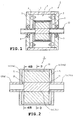
- FIG. 1 shows the construction of an electric rotating machine 1 of the invention in a longitudinal section.
- the electric rotating machine 1 comprises a cylindrical metal frame 2, bearing brackets 3 mounted on both end faces of the frame 2, a stator 4 and a rotor 5.
- the stator 4 comprises a stator core 7 and a stator winding 8.
- the stator core 7 is formed by punching out a magnetic material such as silicon steel sheet into a generally annular shape, whereby a core piece is obtained. A plurality of core pieces are stacked into the stator core 7.
- the stator winding 8 is housed in the stator core 7.
- the stator 4 is fitted in a cylindrical frame 2.
- the frame 2 has both end faces to which bearing brackets 3 are fastened by bolts and nuts respectively. Bearings 9 are mounted on central portions of the both bearing brackets 3 respectively.
- the rotor 5 is rotatably held by the bearings 9 inside the stator 4.
- FIG. 2 is a longitudinal side section of the electric rotating machine including a d-axis of the rotor 5 of a first embodiment.
- the rotor 5 comprises a rotor core 11, permanent magnets 12 (see FIG. 3 ) embedded in the rotor core 11, two presser plates 14a and 14b pressing both end faces of the rotor core 11 respectively, and a rotating shaft 15.
- FIG. 3 is a sectional view of the rotor 5 taken along line 3-3 in FIG. 2 .
- the rotor core 11 is formed by punching out a magnetic material into a planar shape as shown in FIG. 3 , whereby a core piece is obtained. A plurality of the core pieces are stacked and axially crimped.
- the rotating shaft 5 is rotatably fitted in a hole 19 having a central key 18 of the rotor core 11.
- the rotor 5 of the embodiment is of a permanent magnet embedded type.
- a plurality of magnet insertion holes 21 through which the permanent magnets 12 are embedded are provided in a circumference of the rotor core 11.
- FIG. 3 shows the case where the number of poles is 8.
- Magnet insertion holes 21 for one pole comprise two magnet insertion holes 21a and 21b disposed in a V shape as viewed at the rotating shaft 15 side.
- the magnet insertion holes 21 are provided so as to axially run through the rotor core 11.
- Plate-shaped permanent magnets 12 are embedded in the magnet insertion holes 21 respectively.
- the permanent magnets 12 embedded in the magnet insertion holes 21a and 21b and facing the outer circumferential side of the rotor core 11 are magnetized so as to have the same polarity as but the different polarity from the permanent magnets 12 embedded in the neighbor V-shaped magnet insertion holes 21.
- Voids 23a and 23b are formed in both lengthwise sides of each embedded permanent magnet 12 by expanding the magnet insertion holes 21a and 21b respectively.
- a primary purpose of provision of the voids 23a and 23b resides in preventing flux short-circuit, the voids 23a and 23b are also used as a refrigerant channel in the invention as will be described later.
- the void 23a located at the outer circumference side is formed near an outer circumferential face of the rotor core 11.
- the other voids 23b adjacent to each other are formed with a slight gap therebetween.
- a core in the gap connects a core located at the outer circumferential side relative to the V-shaped magnet insertion hole 21 to the inner circumferential side core. Accordingly, the core is called "bridge" 24.
- the magnet insertion holes 21a and 21b are formed so as to be line-symmetric with respect to a line connecting the bridge 24 and the rotating shaft and a shaft center of the rotating shaft 15. Accordingly, magnetic flux produced by the V-shaped permanent magnets 12 is directed to a line connecting the bridge 24 and the shaft center of the rotating shaft 15 at the V-shaped portion.
- the direction of magnetic flux produced by the permanent magnet is called "d-axis.”
- the line connecting the bridge 24 and the shaft center of the rotating shaft 15 corresponds to the d-axis.
- d-axis through-holes 26 are provided so as to be located on the d-axes respectively and at the outer circumferential side relative to the permanent magnets and so as to run through the rotor core 11.
- the d-axis through-holes 26 increases magnetic resistance in the d-axis direction and decreases a d-axis inductance Ld. Consequently, the difference between a q-axis inductance Lq and the d-axis inductance Ld is increased such that reluctance torque is increased.
- the d-axis through-holes 26 are also used as a refrigerant channel in the invention as will be described later.
- a direction with phase lead of ⁇ /2 by electrical angle is called "q-axis" in a dq coordinate system.
- a q-axis is represented by a line connecting the line between the adjacent two voids 23a of the adjacent V-shaped magnet insertion holes 21 and the shaft center of the rotating shaft 15.
- the rotor 5 of the embodiment has q-axis through-holes 27 which are formed on the q-axes so as to axially extend through the rotor core 11.
- the q-axis through-holes 27 contribute to an improvement in responsiveness to rotational speed changes by weight saving, the q-axis through-holes are used as the refrigerant channel in the invention as will be described later.
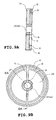
- FIGS. 4A and 4B illustrate an outer configuration of the left presser plate 14a pressing the rotor core 11 as shown in FIG. 2 together with a sectional configuration of the rotating shaft 15 extending through the left presser plate 14a.
- FIG. 4B is a view of a joint surface of the left presser plate 14a and the rotor core 11 (a plane perpendicular to the shaft center including the line 4B-4B in FIG. 2 ) as viewed from the rotor core 11 side.
- FIG. 4A is a sectional view taken along line 4A-4A in FIG. 4B .
- the left presser plate 14a has a surface which is in contact with the rotor core 11 and is formed with two grooves each having a U-shaped section.
- the rotating shaft 15 is inserted through and fixed in the center of the left presser plate 14a.
- the rotating shaft 15 includes hollow shaft portions 15a and 15b and a solid shaft portion 15c as shown in FIG. 2 .
- a part of the rotating shaft 15 inserted through and fixed in the rotor core 11 is formed in the solid shaft portion 15c and parts protruding at both sides of the rotor core 11 are formed in the hollow shaft portions 15a and 15b respectively.
- a hollow shaft wall hole 25 radially extending is formed in a wall face of the hollow shaft portion 15a so as to be located between the solid shaft portion 15c and the hollow shaft portion 15a as shown in FIG. 2 .
- First annular grooves 30 are formed annularly along the circumferences of the presser plates 14a and 14b respectively.
- the first annular grooves 30 are formed at locations where the grooves 30 are connected to the d-axis through-holes 26, respectively.
- Radial grooves 31 are formed in the presser plates 14 and 14 so as to connect the first annular grooves 30 to the hollow shaft wall holes 25 of the rotating shaft 15 respectively. Although two radial grooves 31 and two hollow shaft wall holes 25 are formed as shown in FIGS. 4A and 4B , the numbers of the grooves 31 and holes 25 may be increased.
- the right presser plate 14b pressing the rotor core 11 from the right of the rotor core 11 and the hollow shaft portion 15b are formed so as to be plane-symmetric with the left presser plate 14a and the hollow shaft portion 15a respectively.
- the left and right presser plates 14a and 14b are mounted with the grooved faces being pressed against the rotor core 11.
- a plurality of d-axis through-holes 26 provided in the rotor core 11 are connected by the first annular groves 30 formed in the presser plates 14a and 14b respectively.
- the first annular grooves 30 are connected through the radial grooves 31 and the hollow shaft wall holes 25 of the rotating shaft 30 of the rotating shaft 15 to the inside of the hollow shaft portion 15a of the rotating shaft 15. Consequently, a channel is formed from the inside of the left hollow shaft portion 15a of the rotating shaft 15 to the inside of the right hollow shaft portion 15a.
- the rotating machine 1 of the embodiment as shown in FIG. 1 employs the rotor 5 with the refrigerant channel configured as described above, and the refrigerant is caused to flow through the refrigerant channel so that the rotor 5 is cooled.
- the refrigerant is used oil, water mixed with antiseptic agent, other liquid, cooling air or the like.
- the rotor 5 When the refrigerant is caused to flow through the refrigerant channel provided in the rotor 5, the rotor 5 is cooled such that the temperature increase can be suppressed.
- the surface of the rotor core 11 and the permanent magnets 12 are effectively cooled since the refrigerant flows through the d-axis through-holes provided near the circumference of the rotor core 11. Accordingly, since the temperature increase in the permanent magnets is suppressed and accordingly, the permanent magnets are prevented from demagnetization, a reduction in the developed torque can be avoided.
- the temperature increase in the rotor 5 due to iron loss is suppressed in the rotating machine 1 provided with the rotor 5 configured as described above. Accordingly, higher speed operation can be realized and the size of the rotating machine 1 can be reduced.
- each magnet insertion hole 21 in which the permanent magnet is embedded is divided into two parts centrally along the d-axis.
- the bridge 24 is formed between the divided parts so as to connect the outer circumferential side relative to the magnet insertion holes 21 of the rotor core 11 and the inner circumferential side, and the divided magnet insertion holes 21 are disposed into the V-shape. Consequently, the rotor 5 of the rotating machine 1 can withstand a centrifugal force during high speed rotation, and accordingly, the rotor 5 of the embodiment can be employed in a rotating machine which necessitates higher speed rotation.
- FIG. 6 is a longitudinal section of the rotor 5 of the embodiment.
- FIGS. 7A and 7B illustrate an outer configuration of the left presser plate 14a pressing the rotor core 11 together with a sectional configuration of the rotating shaft 15 extending through the left presser plate 14a.
- FIG. 7B is a view of a joint surface of the left presser plate 14a and the rotor core 11 as viewed from the rotor core 11 side.
- FIG. 7A is a sectional view taken along line 7A-7A in FIG. 7B .
- the right presser plate 14b is formed so as to be plane-symmetric with the left presser plate 14a.
- the rotor 5 of the embodiment differs from the rotor 5 of the first embodiment as shown in FIG. 5 in locations of the annular grooves formed in the faces of the left and right presser plates 14a and 14b in contact with the rotor core 11.
- the first annular groove 30 is formed at a location where the groove 30 connects the d-axis through-holes 26 of the rotor core 11.
- a second annular groove 32 of the second embodiment is formed so as to connect the voids 23b formed by expanding the magnet insertion holes 21a and 21b axially running through.
- the radial groove 31 is formed so as to connect the second annular groove 32 to the hollow shaft wall hole 25 of the rotating shaft 15.
- refrigerant flows through the voids 23b in the rotor core 11, instead of the d-axis through-holes 26, thereby flowing out of the rotor core 11 through the right hollow shaft portion 15a at the opposite side.
- the refrigerant flows into the voids 23b axially running through the rotor core 11 in contact with the permanent magnets 12. Accordingly, the permanent magnets 12 are cooled further effectively. Consequently, since the temperature increase of the permanent magnets is suppressed, the permanent magnets are prevented from demagnetization, whereupon reduction in the developed torque can be avoided.
- FIG. 8 is a longitudinal section of the rotor 5 of the embodiment.
- FIGS. 9A and 9B illustrate an outer configuration of the left presser plate 14a pressing the rotor core 11 together with a sectional configuration of the rotating shaft 15 extending through the left presser plate 14a.
- FIG. 9B is a view of a joint surface of the left presser plate 14a and the rotor core 11 as viewed from the rotor core 11 side.
- FIG. 9A is a sectional view taken along line 9A-9A in FIG. 9B .
- the right presser plate 14b is formed so as to be plane-symmetric with the left presser plate 14a.
- the rotor 5 of the embodiment differs from the rotors 5 of the first and second embodiments in the construction of the annular grooves formed in the faces of the left and right presser plates 14a and 14b in contact with the rotor core 11.
- the third embodiment is provided with both first annular groove 30 provided in the first embodiment and second annular groove 32 provided in the second embodiment.
- the first annular groove 30 connects the plural d-axis through-holes 26 provided in the rotor core 11, and the second annular groove 32 connects the voids 23b formed by expanding the magnet insertion holes 21a and 21b so as to axially run through the rotor core 11.
- the void 23a located at the outer circumferential side of the rotor core 11 has substantially the same distance from the shaft center of the rotor core 11 as the d-axis through hole 26. Accordingly, the first annular groove 30 has a width adjusted so as to connect the voids 23a as well as the d-axis through-holes 26.
- the radial grooves 31 are formed so as to connect the first and second annular grooves to the hollow shaft wall holes 25 of the rotating shaft 15.
- the refrigerant when poured into the left hollow shaft portion 15a of the rotating shaft 15 as shown in FIG. 8 , the refrigerant passes through three types of through-holes, that is, the d-axis through-holes 26, voids 23a and voids 23b in parallel in the rotor core 11. After having passed through these through-holes, the refrigerant then flows out of the rotor core 11 through the right hollow shaft portion 15a at the opposite side.
- the refrigerant flows through the three types of through-holes, that is, the d-axis through-holes 26, voids 23a, voids 23b in the rotor core 11. Accordingly, since the permanent magnets 12 and the rotor core 11 are cooled further effectively, reduction in the developed torque can be avoided.
- FIG. 10 is a longitudinal section of the rotor 5 of the embodiment.
- FIGS. 11A and 11B illustrate an outer configuration of the left presser plate 14a pressing the rotor core 11 together with a sectional configuration of the rotating shaft 15 extending through the left presser plate 14a.
- FIG. 11B is a view of a joint surface of the left presser plate 14a and the rotor core 11 as viewed from the rotor core 11 side.
- FIG. 11A is a sectional view taken along line 11A-11A in FIG. 11B .
- the right presser plate 14b is formed so as to be plane-symmetric with the left presser plate 14a.
- the rotor 5 of the embodiment differs from the rotor 5 of the third embodiment in the construction of the annular grooves formed in the faces of the left and right presser plates 14a and 14b in contact with the rotor core 11.
- the fourth embodiment is provided with third annular grooves 33 in addition to the first and second annular grooves 30 and 32 provided in the third embodiment.
- the third annular grooves 33 are formed so as to connect the q-axis through-holes 27 described with reference to FIG. 3 . More specifically, in the fourth embodiment, the d-axis through-holes 26 and the voids 23a are connected by the first annular grooves 30.
- the voids 23b are connected by the second annular grooves 32.
- the q-axis through-holes 27 are connected by the third annular grooves 33.
- the radial grooves 31 are formed so as to connect the first, second and third annular grooves 30, 32 and 33 to the hollow shaft wall holes 25 of the rotating shaft 15.
- the refrigerant flows through four types of through-holes, that is, the d-axis through-holes 26, voids 23a, voids 23b and the q-axis through-holes 27 in parallel in the rotor core 11. Accordingly, the permanent magnets 12 and the rotor core 11 are cooled in the fourth embodiment more effectively than in the third embodiment. Consequently, the temperature increase in the permanent magnets 12 is suppressed and demagnetization of the permanent magnets 12 is prevented, whereupon reduction in the developed torque can be avoided.
- FIG. 12 is a longitudinal section of the rotor 5 of the embodiment.
- FIG. 13A is a view of the left presser plate 14a pressing the rotor core 11 from the left side as viewed from the rotor core 11 side.
- FIG. 13B is a view of the right presser plate 14b pressing the rotor core 11 from the right side as viewed from the rotor core 11 side.
- the figures also show the section of the rotating shaft 15 running through the shown portions of the rotor core 11.
- the left presser plate 14a of the embodiment as shown in FIG. 13A is formed by adding presser plate refrigerant outlets 35 to the left presser plate 14a of the third embodiment as shown in FIGS. 9A and 9B so that the presser plate refrigerant outlets 35 are located at positions opposed to the q-axis through-holes 27 (see FIG. 3 ) at the rotor core 11 side.
- the annular grooves include the first annular grooves 30 connecting the d-axis through-holes 26 and the voids 23a as in the third embodiment and the second annular grooves 32 connecting the voids 23b.
- the right presser plate 14b of the embodiment as shown in FIG. 13B has a changed construction of the radial grooves 31 in the right presser plate 14b plane-symmetric with the left presser plate 14a of the fourth embodiment as shown in FIGS. 11A and 11B .
- the radial grooves 31 connect the first, second and third annular grooves 30, 32 and 33 to one another.
- the rotating shaft 15 includes a whole part thereof formed into a hollow shaft as shown in FIG. 12 , only a part thereof inserted through the rotor core 11 may be formed into a hollow shaft as in the rotating shaft 15 of the fourth embodiment as shown in FIG. 10 .
- the rotating shaft 15 as shown in FIG. 29 may include a part from the end at the refrigerant inlet side to a portion communicating with the hollow shaft wall hole 25. The part may be formed into a hollow shaft and the other part may be formed into a solid shaft.
- the refrigerant flows as shown by arrows in FIG. 12 .
- the refrigerant flows through the through-holes, that is, the d-axis through-holes 26, voids 23a, voids 23b and q-axis through-holes 27 in the rotor core 11, whereby the permanent magnets 12 and the rotor core 11 are cooled. Accordingly, the temperature increase in the permanent magnets 12 is suppressed and demagnetization of the permanent magnets 12 is prevented, whereupon reduction in the developed torque can be avoided.
- FIG. 12 is a longitudinal section of the rotor 5 of the embodiment.
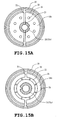
- FIG. 15A is a view of the left presser plate 14a pressing the rotor core 11 from the left side as viewed from the rotor core 11 side.
- FIG. 15B is a view of the right presser plate 14b pressing the rotor core 11 from the right side as viewed from the rotor core 11 side.
- the figures also show the section of the rotating shaft 15 running through the shown portions of the rotor core 11.
- the rotating shaft 15 includes a whole part thereof formed into a hollow shaft as shown in FIG. 14 , only a part thereof inserted through the rotor core 11 may be formed into a hollow shaft as in the rotating shaft 15 of the fourth embodiment as shown in FIG. 10 .
- the rotating shaft 15 as shown in FIG. 29 may include a part from the end at the refrigerant inlet side to a portion communicating with the hollow shaft wall hole 25. The part may be formed into a hollow shaft and the other part may be formed into a solid shaft.
- the refrigerant flows as shown by arrows in FIG. 14 .
- the refrigerant flows through the through-holes, that is, the d-axis through-holes 26, voids 23a and voids 23b in parallel from the left toward the right in the rotor core 11.
- the refrigerant then flows into the radial groove 31 of the right presser plate 14b.
- part of the refrigerant flows outside the rotor core 11 through the presser plate refrigerant outlet 35 provided at the position opposed to the q-axis through-hole 27.
- the remaining refrigerant turns around thereby to flow through the q-axis through-hole 27 of the rotor core 11 from the right toward the left, flowing outside the rotor core 11 through the presser plate refrigerant outlet hole 35 located opposite the q-axis through-hole 27 provided in the left presser plate 14a. More specifically, the refrigerant flows outside the rotor core 11 through the presser plate refrigerant outlet holes 35 located opposite the q-axis through-holes 27 of the left and right presser plates 14a and 14b respectively in the embodiment.
- the refrigerant flows through the through-holes, that is, the d-axis through-holes 26, voids 23a, voids 23b and q-axis through-holes 27 in the rotor core 11, whereby the permanent magnets 12 and the rotor core 11 are cooled. Accordingly, the temperature increase in the permanent magnets 12 is suppressed and demagnetization of the permanent magnets 12 is prevented, whereupon reduction in the developed torque can be avoided. Furthermore, since the refrigerant is caused to flow out of the presser plate refrigerant outlet holes 35, the stator 45 can also be cooled.
- FIGS. 16 , 17A and 17B identical or similar parts are labeled by the same reference symbols as those in FIGS. 10 , 11A and 11B of the fourth embodiment.
- FIG. 17A is a view of the left presser plate 14a pressing the rotor core 11 from the left side as viewed from the rotor core 11 side.
- FIG. 17B is a view of the right presser plate 14b pressing the rotor core 11 from the right side as viewed from the rotor core 11 side.
- the figures also show the section of the rotating shaft 15 running through the shown portions of the rotor core 11.
- the rotor 5 of the embodiment differs from the rotor 5 of the fourth embodiment in the additional provision of a plurality of presser plate refrigerant outlet holes 35 in the third annular groove 33 formed in the faces of the left and right presser plates 14a and 14b in contact with the rotor core 11 and in that the radial groove 33 of the right presser plate 14b connects only the first, second and third annular grooves 30, 32 and 33 to one another.
- the added presser plate refrigerant outlet holes 35 are arranged equiangularly and may or may not be provided so as to be opposite the q-axis through-holes 27 (see FIG. 3 ) of the rotor core 11.
- the presser plate refrigerant outlet holes 35 provided in the left presser plate 14a have smaller diameters than the presser plate refrigerant outlet holes 35 of the right presser plate 14b.
- the rotating shaft 15 includes a whole part thereof formed into a hollow shaft as shown in FIG. 16 , only a part thereof inserted through the rotor core 11 may be formed into a hollow shaft as in the rotating shaft 15 of the fourth embodiment as shown in FIG. 10 .
- the rotating shaft 15 as shown in FIG. 29 may include a part from the end at the refrigerant inlet side to a portion communicating with the hollow shaft wall hole 25. The part may be formed into a hollow shaft and the other part may be formed into a solid shaft.
- the refrigerant also flows through the through-holes in the embodiment, that is, the d-axis through-holes 26, voids 23a, voids 23b and q-axis through-holes 27 in the rotor core 11, whereby the permanent magnets 12 and the rotor core 11 are cooled. Accordingly, the temperature increase in the permanent magnets 12 is suppressed and demagnetization of the permanent magnets 12 is prevented, whereupon reduction in the developed torque can be avoided.
- FIGS. 18 , 19A and 19B The rotor of an eighth embodiment of the invention will now be described with reference to FIGS. 18 , 19A and 19B .
- identical or similar parts are labeled by the same reference symbols as those in FIGS. 4A, 4B and 5 of the first embodiment.
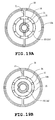
- FIG. 19A is a view of the left presser plate 14a pressing the rotor core 11 from the left side as viewed from the rotor core 11 side.
- FIG. 19B is a view of the right presser plate 14b pressing the rotor core 11 from the right side as viewed from the rotor core 11 side.
- the figures also show the section of the rotating shaft 15 running through the shown portions of the rotor core 11.
- the rotor 5 of the embodiment differs from the rotor 5 of the first embodiment in the additional provision of fourth annular grooves 34 in the left and right presser plates 14a and 14b and in that a plurality of presser plate outlet holes 35 which are formed in the bottom of the fourth annular grooves 34 and communicate with the axial outside, as shown in FIGS. 19A and 19B .
- the fourth annular grooves 34 are formed inside relative to the first annular grooves 30.
- the added presser plate refrigerant outlet holes 35 are arranged equiangularly.
- the presser plate refrigerant outlet holes 35 provided in the left presser plate 14a have smaller diameters than the presser plate refrigerant outlet holes 35 of the right presser plate 14b.
- the radial groove 31 of the left presser plate 14a is formed so as to connect the first and fourth annular grooves 30 and 34 to the hollow shaft wall holes 25, and the radial groove 31 of the right presser plate 14b is formed so as to connect the first and fourth annular grooves 30 and 34 to each other.
- the rotating shaft 15 includes a whole part thereof formed into a hollow shaft as shown in FIG. 16 , only a part thereof inserted through the rotor core 11 may be formed into a hollow shaft as in the rotating shaft 15 of the fourth embodiment as shown in FIG. 5 .
- the rotating shaft 15 as shown in FIG. 29 may include a part from the end at the refrigerant inlet side to a portion communicating with the hollow shaft wall hole 25. The part may be formed into a hollow shaft and the other part may be formed into a solid shaft.
- the refrigerant flows as shown by arrows in FIG. 18 .
- Part of the refrigerant having flowed in the radial groove 31 of the left presser plate 14a flows out of the rotor core 11 through the fourth annular groove 34 and the presser plate refrigerant outlet holes 35 without passing through the through holes provided in the rotor core 11.
- the refrigerant flows into the first annular groove 30 of the right presser plate 14b though the d-axis through-hole 26 axially running through the rotor core 11, further flowing out of the rotor core 11 through the presser plate refrigerant outlet holes 35 provided in the fourth annular groove 34.
- the refrigerant also flows through the d-axis through-holes 26 in the embodiment, whereby the permanent magnets 12 and the rotor core 11 are cooled. Accordingly, the temperature increase in the permanent magnets 12 is suppressed and demagnetization of the permanent magnets 12 is prevented, whereupon reduction in the developed torque can be avoided.
- FIGS. 20 , 21A and 21B identical or similar parts are labeled by the same reference symbols as those in FIGS. 6 , 7A and 7B of the second embodiment.
- FIG. 21A is a view of the left presser plate 14a pressing the rotor core 11 from the left side as viewed from the rotor core 11 side.
- FIG. 21B is a view of the right presser plate 14b pressing the rotor core 11 from the right side as viewed from the rotor core 11 side.
- the figures also show the section of the rotating shaft 15 running through the shown portions of the rotor core 11.
- the rotor 5 of the embodiment differs from the rotor 5 of the second embodiment in the additional provision of fourth annular grooves 34 in the left and right presser plates 14a and 14b and in that a plurality of presser plate outlet holes 35 which are formed in the bottom of the fourth annular grooves 34 and communicate with the axial outside, as shown in FIGS. 19A and 19B .
- the fourth annular grooves 34 are formed inside relative to the second annular grooves 32.
- the added presser plate refrigerant outlet holes 35 are arranged equiangularly.
- the presser plate refrigerant outlet holes 35 provided in the left presser plate 14a have smaller diameters than the presser plate refrigerant outlet holes 35 of the right presser plate 14b.
- the radial groove 31 of the left presser plate 14a is formed so as to connect the second and fourth annular grooves 32 and 34 to the hollow shaft wall holes 25, and the radial groove 31 of the right presser plate 14b is formed so as to connect the second and fourth annular grooves 32 and 34 to each other.
- the rotating shaft 15 includes a whole part thereof formed into a hollow shaft as shown in FIG. 20 , only a part thereof inserted through the rotor core 11 may be formed into a hollow shaft as in the rotating shaft 15 of the second embodiment as shown in FIG. 6 .
- the rotating shaft 15 as shown in FIG. 29 may include a part from the end at the refrigerant inlet side to a portion communicating with the hollow shaft wall hole 25. The part may be formed into a hollow shaft and the other part may be formed into a solid shaft.
- the refrigerant also flows through the void 23b of the rotor core 11 in the embodiment, whereby the permanent magnets 12 and the rotor core 11 are cooled. Accordingly, the temperature increase in the permanent magnets 12 is suppressed and demagnetization of the permanent magnets 12 is prevented, whereupon reduction in the developed torque can be avoided.
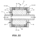
- FIGS. 22 , 23A and 23B The rotor of a tenth embodiment of the invention will now be described with reference to FIGS. 22 , 23A and 23B .
- identical or similar parts are labeled by the same reference symbols as those in FIGS. 8 , 9A and 9B of the third embodiment.
- FIG. 23A is a view of the left presser plate 14a pressing the rotor core 11 from the left side as viewed from the rotor core 11 side.
- FIG. 23B is a view of the right presser plate 14b pressing the rotor core 11 from the right side as viewed from the rotor core 11 side.
- the figures also show the section of the rotating shaft 15 running through the shown portions of the rotor core 11.
- the rotor 5 of the embodiment differs from the rotor 5 of the third embodiment in the additional provision of fourth annular grooves 34 in the left and right presser plates 14a and 14b and in that a plurality of presser plate outlet holes 35 which are formed in the bottom of the fourth annular grooves 34 and communicate with the axial outside, as shown in FIGS. 23A and 23B .
- the fourth annular grooves 34 are formed inside relative to the second annular grooves 32.
- the added presser plate refrigerant outlet holes 35 are arranged equiangularly.
- the presser plate refrigerant outlet holes 35 provided in the left presser plate 14a have smaller diameters than the presser plate refrigerant outlet holes 35 of the right presser plate 14b.
- the radial groove 31 of the left presser plate 14a is formed so as to connect the first, second and fourth annular grooves 30, 32 and 34 to the hollow shaft wall holes 25, and the radial groove 31 of the right presser plate 14b is formed so as to connect the first, second and fourth annular grooves 30, 32 and 34 to each other.
- the rotating shaft 15 includes a whole part thereof formed into a hollow shaft as shown in FIG. 22 , only a part thereof inserted through the rotor core 11 may be formed into a hollow shaft as in the rotating shaft 15 of the third embodiment as shown in FIG. 8 .
- the rotating shaft 15 as shown in FIG. 29 may include a part from the end at the refrigerant inlet side to a portion communicating with the hollow shaft wall hole 25. The part may be formed into a hollow shaft and the other part may be formed into a solid shaft.
- the refrigerant flows as shown by arrows in FIG. 22 .
- Part of the refrigerant having flowed in the radial groove 31 of the left presser plate 14a flows out of the rotor core 11 through the fourth annular groove 34 and the presser plate refrigerant outlet holes 35.
- the refrigerant flows into the first and second annular grooves 30 and 32 of the right presser plate 14b through the d-axis through-holes 26 axially running through the rotor core 11, the void 23a and the void 23b, further flowing out of the rotor core 11 through the presser plate refrigerant outlet holes 35 provided in the fourth annular groove 34.
- the refrigerant also flows through the d-axis through-holes 26, void 23a and void 23b of the rotor core 11 in the embodiment, whereby the permanent magnets 12 and the rotor core 11 are cooled. Accordingly, the temperature increase in the permanent magnets 12 is suppressed and demagnetization of the permanent magnets 12 is prevented, whereupon reduction in the developed torque can be avoided.
- the rotor 5 of the embodiment differs from the rotor 5 of the first embodiment in the additional provision of auxiliary plates 41a and 41b interposed between both axial end faces of the rotor core 11 and the left and right presser plates 14a and 14b respectively.
- the auxiliary plates 41a and 41b have the same outer diameter as the presser plates 14a and 14b and are centrally formed with fitting holes 42 through which the rotating shaft 15 is inserted thereby to be fixed.
- the auxiliary plates 41a and 41b have the same shape.
- the auxiliary plates 41a and 41b are each formed into a flat shape and each have eight passing holes 43 formed in an outer circumferential edge equiangularly.
- the passing holes 43 are formed so as to communicate with the d-axis through-holes 26 when disposed so as to abut against both end faces of the rotor core 11.
- the auxiliary plates 41a and 41b are interposed between the end faces of the rotor core 11 and the left and right presser plates 14a and 14b respectively, whereupon the voids 23a and 23b formed in the rotor core 11 and the q-axis through-holes 27 can be closed.
- the loss of the rotor 5 resulting from harmonic flux due to stator 4 side slots that is, iron loss, is easier to occur on the surface of the rotor 5.
- the loss on the surface of the rotor core 11 tends to be increased with speed-up of rotation of the electric rotating machine 1.
- the temperature of the magnets 12 of the rotor 5 may be decreased, it is effective to cool the surface and the vicinity thereof or a primary heating portion of the rotor core 11.
- the refrigerant since the refrigerant also flows only through the d-axis through-holes 26 of the rotor core 11 when poured into the left hollow shaft portion 15a, the permanent magnets 12 and the rotor core 11 are cooled by a limited amount of refrigerant further effectively. Consequently, the temperature increase in the permanent magnets 12 is suppressed and demagnetization of the permanent magnets 12 is prevented, whereupon reduction in the developed torque can be avoided.
- FIG. 26 is a view of an auxiliary plate 44a as viewed from the rotor core 11 side. The figure also shows the section of the rotating shaft 15 running through the shown portions of the rotor core 11.
- the rotor 5 of the embodiment differs from the rotor 5 of the first embodiment in the provision of presser plates 44a and 44b provided on both axial end faces of the rotor core 11, instead of the presser plates 14a and 14b.
- the presser plates 44a and 44b have the same outer diameter as the presser plates 14a and 14b and are centrally formed with fitting holes 45 through which the rotating shaft 15 is inserted thereby to be fixed.
- the presser plates 44a and 44b have the same shape with an exception that the fitting hole 45 is symmetrical about the rotor core 11.
- Annularly recessed entry portions 46 are formed in faces of the presser plates 44a and 44b abutting against the rotor core 11.
- the fitting holes 45 and the entry portions 46 are connected together only by a pair of communication channels 47 disposed at upper and lower positions so as to be opposed on a circumference. Furthermore, eight narrow grooves 48 are formed in side faces abutting against the rotor core 11 so as to radially extend outward from outer edges of the entry portions. The grooves 48 are formed in an outer circumferential edge equiangularly. Since the presser plates 44a and 44b are disposed on both end faces of the rotor core 11 respectively, the narrow grooves 48 extend so as to be opposed between the voids 23a of the rotor core 11 (bridge 24). Accordingly, the hollow shaft portions 15a and 15b of rotating shaft 15 communicate with only the d-axis through-holes 26 through the hollow shaft wall hole 25, communication channels 47, entry portions 46 and narrow grooves 48.
- the refrigerant since the refrigerant also flows only through the d-axis through-holes 26 of the rotor core 11 when poured into the left hollow shaft portion 15a, the permanent magnets 12 and the rotor core 11 are cooled by a limited amount of refrigerant further effectively. Consequently, the temperature increase in the permanent magnets 12 is suppressed and demagnetization of the permanent magnets 12 is prevented, whereupon reduction in the developed torque can be avoided.
- the voids 23a and 23b and the q-axis through-holes 27 formed in the rotor core 11 may be sealed by a synthetic resin material or the like so that the refrigerant poured into the hollow shaft portion 15a is prevented from flowing therethrough, instead of the interposition of the auxiliary plates 41a and 41b between both axial end faces of the rotor core 11 and the left and right presser plates 14a and 14b as in the eleventh embodiment or the provision of the presser plates 44a and 44b on both axial end faces of the rotor core 11 as in the twelfth embodiment.
- FIG. 28 shows an example of the construction of a rotating machine 1a employing the rotor 5 of the seventh embodiment as shown in FIG. 16 .
- the refrigerant poured into the left hollow shaft portion 15a of the rotating shaft 15 flows in the rotor core 11, thereafter flowing out of presser plate refrigerant outlet holes 35 provided in the left and right presser plates 14a and 14b, as described above.
- case refrigerant outlet holes 37 are provided in the left and right bearing brackets 3 in the electric rotating machine 1a of FIG. 28 in order that the refrigerant flowing out of the presser plate refrigerant outlet holes 35 may be caused to flow out of the electric rotating machine 1a.
- the refrigerant When poured into the left hollow shaft portion 15a of the rotating shaft 15 in the electric rotating machine 1a, the refrigerant is discharged from the rotor 5 through four types of through holes, that is, the d-axis through-holes 26, voids 23a, voids 23b and q-axis through-holes 27 in the rotor core 11. Accordingly, the permanent magnets 12 and the rotor core 11 are cooled effectively as in the seventh embodiment. Furthermore, the refrigerant discharged from the rotor 5 fills an electric rotating machine case comprising the frame 2 and the right and left brackets 3 and is thereafter discharged through the case refrigerant outlet holes 37 outside the electric rotating machine 1a. Thus, the stator 4 fitted in the frame 2 is also cooled by the refrigerant.
- the rotor for electric rotating machine and the electric rotating machine of the invention are applicable to general machines, machine tools, vehicles, boats and ships and the like.
Landscapes
- Engineering & Computer Science (AREA)
- Power Engineering (AREA)
- Iron Core Of Rotating Electric Machines (AREA)
- Permanent Field Magnets Of Synchronous Machinery (AREA)
- Motor Or Generator Cooling System (AREA)
Abstract
Description
- The present invention relates to an electric rotating machine using a permanent magnet, and more particularly to a rotor for such an electric rotating machine in which the permanent magnet and a rotor core can be cooled by a refrigerant, and the electric rotating machine provided with the rotor.
- Recent electric rotating machines have been reduced in size by employment of a structure of embedding a permanent magnet in a rotor, a technique of utilizing reluctance torque by giving a magnetically salient polarity to a rotor as well as magnetic torque, and the like. One of present problems to be overcome is considered to increase a rotational speed of a rotor.
- However, an iron loss (the sum of hysteresis loss and eddy current loss) induced in a rotor core is increased and particularly an iron loss induced near a surface of the iron core is increased when the rotational speed is increased. Furthermore, an eddy current loss induced in a permanent magnet embedded in a rotor core is not negligible, either. When heat generation due to these losses increases a temperature of the permanent magnet, the permanent magnet is demagnetized such that induced torque is reduced. Additionally, an increase in a temperature of the rotor core also reduces magnetic permeability of the core thereby to reduce the induced torque.
- Various structures for cooling the rotor have conventionally been proposed for the purpose of suppressing a temperature increase in the rotor. For example,
Patent Document 1 proposes a cooling structure in which cavities are formed so as to axially extend through a rotor core and openings are formed in both presser plates of the rotor core located opposite the cavities respectively. Partition plates which are longer than an axial dimension of the rotor are mounted in the cavities and the openings respectively. In the structure, however, the cooling performance is low since cooling by air is employed. - Furthermore,
Patent Document 2 proposes a cooling structure in which cooling channels are formed on inner peripheral sides of embedded permanent magnets so as to extend through the rotor core. Each cooling channel has a section formed to be convex in a direction of the rotation center. A refrigerant is adapted to be caused to flow through the cooling channels. This structure would be insufficient in the performance to cool a rotor core although effective for the cooling of permanent magnets. - Patent Document 1:
JP-A-2002-78291 - Patent Document 2:
JP-A-2002-345188 - The present invention was made to overcome the foregoing problems of the conventional technique, and the subject matter thereof is to facilitate high speed and size reduction in the electric rotating machine by improving the cooling performance for the rotor thereof.
- A rotor for an electric rotating machine and an electric rotating machine according to the present invention having a structure that permanent magnets are embedded in a plurality of magnet insertion holes axially extending through a circumference of a cylindrical rotor core and a rotating shaft extends through a central portion of the of the rotor core thereby to be fixed, are characterized by a d-axis through hole provided on each d-axis corresponding to a direction of magnetic flux so as to extend in an axial direction in an outer circumferential side relative to each embedded permanent magnet, a hollow shaft formed in at least one side of a portion of the rotating shaft not inserted into the rotor core, presser plates mounted on both axial ends of the rotor core so as to hold the rotor core therebetween, a hollow shaft wall hole formed in a hollow shaft wall of the hollow shaft of the rotating shaft so as to axially extend through the hollow shaft, and a cooling groove formed in a face of at least one of the presser plates in contact with the rotor core, so as to connect the hollow shaft wall hole and each d-axis through hole provided in the rotor core.
- In the rotor for an electric rotating machine and the electric rotating machine of the invention, when the rotor is thus constructed and refrigerant is caused to flow from the hollow shaft of the rotating shaft, the rotor is cooled such that temperature increase thereof can be suppressed. Since the refrigerant flows through the d-axis through holes provided near the rotor core particularly in the construction, a surface layer of the rotor core and the permanent magnets can effectively be cooled. Accordingly, a reduction in the developed torque can be avoided since the temperature increase in the permanent magnets can be suppressed and the demagnetization can be prevented.
-
-
FIG. 1 is a longitudinal side section of an electricrotating machine 1 of the invention; -
FIG. 2 is a longitudinal side section of the electric rotating machine including a d-axis of arotor 5 of a first embodiment; -
FIG. 3 is a sectional view taken along line perpendicular to the axis of the rotor in accordance with the invention; -
FIG. 4A is a sectional view taken alongline 4A-4A inFIG. 4B ; -
FIG. 4B is a front view of aleft presser plate 14a pressing arotor core 11 of therotor 5 in the first embodiment; -
FIG. 5 is a view explaining flow channels in the case where a refrigerant is caused to flow through therotor 5 in the first embodiment; -
FIG. 6 is a view similar toFIG. 5 , showing therotor 5 in a second embodiment; -
FIG. 7A is a sectional view taken alongline 7A-7A inFIG. 7B ; -
FIG. 7B is a view similar toFIG. 4b , showing therotor 5 in the second embodiment; -
FIG. 8 is a view similar toFIG. 5 , showing therotor 5 in a third embodiment; -
FIG. 9A is a sectional view taken alongline 9A-9A inFIG. 9B ; -
FIG. 9B is a view similar toFIG. 4B , showing therotor 5 in the fourth embodiment; -
FIG. 10 is a view similar toFIG. 5 , showing therotor 5 of a fourth embodiment; -
FIG. 11A is a sectional view taken alongline 11A-11A inFIG. 11B ; -
FIG. 11B is view similar toFIG. 4B , showing therotor 5 of the fourth embodiment; -
FIG. 12 is a view similar toFIG. 5 , showing therotor 5 of a fifth embodiment; -
FIG. 13A is a front view of theleft presser plate 14a in therotor 5 of the fifth embodiment as viewed at therotor core 11 side; -
FIG. 13B is a front view of theright presser plate 14b in therotor 5 of the fifth embodiment as viewed at therotor core 11 side; -
FIG. 14 is view similar toFIG. 5 , showing therotor 5 of a sixth embodiment; -
FIG. 15A is a front view of theleft presser plate 14a in therotor 5 of the sixth embodiment as viewed at therotor core 11 side; -
FIG. 15B is a front view of theright presser plate 14b in therotor 5 of the sixth embodiment as viewed at therotor core 11 side; -
FIG. 16 is a view similar toFIG. 5 , showing therotor 5 of a seventh embodiment; -
FIG. 17A is a front view of theright presser plate 14a in therotor 5 of the seventh embodiment as viewed at therotor core 11 side; -
FIG. 17B is a front view of theright presser plate 14b in therotor 5 of the seventh embodiment as viewed at therotor core 11 side; -
FIG. 18 is a view similar toFIG. 5 , showing therotor 5 of an eighth embodiment; -
FIG. 19A is a front view of theleft presser plate 14a in therotor 5 of the eighth embodiment as viewed at therotor core 11 side; -
FIG. 19B is a front view of theright presser plate 14b in therotor 5 of the eighth embodiment as viewed at therotor core 11 side; -
FIG. 20 is a view similar toFIG. 5 , showing therotor 5 of a ninth embodiment; -
FIG. 21A is a front view of theleft presser plate 14a in therotor 5 of the ninth embodiment as viewed at therotor core 11 side; -
FIG. 21B is a front view of theright presser plate 14b in therotor 5 of the ninth embodiment as viewed at therotor core 11 side; -
FIG. 22 is a view similar toFIG. 5 , showing therotor 5 of a tenth embodiment; -
FIG. 23A is a front view of theleft presser plate 14a in therotor 5 of the tenth embodiment as viewed at therotor core 11 side; -
FIG. 23B is a front view of theright presser plate 14b in therotor 5 of the tenth embodiment as viewed at therotor core 11 side; -
FIG. 24 is a front view of the leftauxiliary plate 14a in therotor 5 of an eleventh embodiment as viewed at therotor core 11 side; -
FIG. 25 is a view similar toFIG. 5 , showing therotor 5 of the eleventh embodiment; -
FIG. 26 is a view similar toFIG. 4B , showing therotor 5 of a twelfth embodiment; -
FIG. 27 is a view similar toFIG. 5 , showing therotor 5 of the twelfth embodiment; -
FIG. 28 is a view explaining flow channels in the case where a refrigerant is caused to flow through therotor 5 in the seventh embodiment; and -
FIG. 29 is a view showing a modified form of therotating shaft 15 of the rotor as shown inFIG. 14 . -
Reference symbols 1 and 1a designate electric rotating machines respectively, 5 a rotor (electric rotating machine rotor), 26 a d-axis through hole, 11 a rotor core, 12 permanent magnet, 14a, 14b, 44a and 44b presser plates respectively, 15 a rotating shaft, 15a and 15b a hollow shaft portion of the rotating shaft, 15c a central shaft portion of the rotating shaft, 21, 21a and 21b magnet insertion holes respectively, 23, 23a and 23b voids respectively, 24 a bridge, 25 a hollow shaft wall hole, 27 q-axis through holes, 30 a first annular groove, 31 a radial groove, 32 a second annular groove, 33 a third annular groove, 34 a fourth annular groove, 35 a presser plate refrigerant outlet hole and 37 a case refrigerant outlet hole. - A rotor for an electric rotating machine and a n electric rotating machine of the present invention will be described with reference to the drawings.
FIG. 1 shows the construction of an electricrotating machine 1 of the invention in a longitudinal section. The electricrotating machine 1 comprises acylindrical metal frame 2, bearingbrackets 3 mounted on both end faces of theframe 2, astator 4 and arotor 5. - The
stator 4 comprises astator core 7 and a stator winding 8. Thestator core 7 is formed by punching out a magnetic material such as silicon steel sheet into a generally annular shape, whereby a core piece is obtained. A plurality of core pieces are stacked into thestator core 7. The stator winding 8 is housed in thestator core 7. Thestator 4 is fitted in acylindrical frame 2. Theframe 2 has both end faces to which bearingbrackets 3 are fastened by bolts and nuts respectively.Bearings 9 are mounted on central portions of the both bearingbrackets 3 respectively. Therotor 5 is rotatably held by thebearings 9 inside thestator 4. -
FIG. 2 is a longitudinal side section of the electric rotating machine including a d-axis of therotor 5 of a first embodiment. Therotor 5 comprises arotor core 11, permanent magnets 12 (seeFIG. 3 ) embedded in therotor core 11, twopresser plates rotor core 11 respectively, and arotating shaft 15.FIG. 3 is a sectional view of therotor 5 taken along line 3-3 inFIG. 2 . Therotor core 11 is formed by punching out a magnetic material into a planar shape as shown inFIG. 3 , whereby a core piece is obtained. A plurality of the core pieces are stacked and axially crimped. Therotating shaft 5 is rotatably fitted in ahole 19 having acentral key 18 of therotor core 11. - The
rotor 5 of the embodiment is of a permanent magnet embedded type. A plurality of magnet insertion holes 21 through which thepermanent magnets 12 are embedded are provided in a circumference of therotor core 11.FIG. 3 shows the case where the number of poles is 8. Magnet insertion holes 21 for one pole comprise twomagnet insertion holes rotating shaft 15 side. The magnet insertion holes 21 are provided so as to axially run through therotor core 11. Plate-shapedpermanent magnets 12 are embedded in the magnet insertion holes 21 respectively. Thepermanent magnets 12 embedded in themagnet insertion holes rotor core 11 are magnetized so as to have the same polarity as but the different polarity from thepermanent magnets 12 embedded in the neighbor V-shaped magnet insertion holes 21.Voids permanent magnet 12 by expanding themagnet insertion holes voids voids - Of the voids located at both sides of the magnet, the void 23a located at the outer circumference side is formed near an outer circumferential face of the
rotor core 11. Theother voids 23b adjacent to each other are formed with a slight gap therebetween. A core in the gap connects a core located at the outer circumferential side relative to the V-shapedmagnet insertion hole 21 to the inner circumferential side core. Accordingly, the core is called "bridge" 24. - The
magnet insertion holes bridge 24 and the rotating shaft and a shaft center of therotating shaft 15. Accordingly, magnetic flux produced by the V-shapedpermanent magnets 12 is directed to a line connecting thebridge 24 and the shaft center of therotating shaft 15 at the V-shaped portion. In a d-q coordinate system known in a biaxial theory, the direction of magnetic flux produced by the permanent magnet is called "d-axis." In therotor 5 of the embodiment, the line connecting thebridge 24 and the shaft center of therotating shaft 15 corresponds to the d-axis. - In the
rotor 5 as shown inFIG. 3 , d-axis through-holes 26 are provided so as to be located on the d-axes respectively and at the outer circumferential side relative to the permanent magnets and so as to run through therotor core 11. The d-axis through-holes 26 increases magnetic resistance in the d-axis direction and decreases a d-axis inductance Ld. Consequently, the difference between a q-axis inductance Lq and the d-axis inductance Ld is increased such that reluctance torque is increased. Furthermore, at the same time, since the mass of the iron core located at the outer circumferential side relative to the V-shapedmagnet insertion hole 21 is reduced, a centrifugal force exerted on this part is reduced whereupon high speed rotation can be realized. Although a primary purpose of provision of the d-axis through-holes 26 resides in the foregoing point, the d-axis through-holes 26 are also used as a refrigerant channel in the invention as will be described later. - A direction with phase lead of π/2 by electrical angle is called "q-axis" in a dq coordinate system. In the
rotor 5 shown inFIG. 3 , a q-axis is represented by a line connecting the line between the adjacent twovoids 23a of the adjacent V-shaped magnet insertion holes 21 and the shaft center of therotating shaft 15. Therotor 5 of the embodiment has q-axis through-holes 27 which are formed on the q-axes so as to axially extend through therotor core 11. Although the q-axis through-holes 27 contribute to an improvement in responsiveness to rotational speed changes by weight saving, the q-axis through-holes are used as the refrigerant channel in the invention as will be described later. -
FIGS. 4A and 4B illustrate an outer configuration of theleft presser plate 14a pressing therotor core 11 as shown inFIG. 2 together with a sectional configuration of therotating shaft 15 extending through theleft presser plate 14a.FIG. 4B is a view of a joint surface of theleft presser plate 14a and the rotor core 11 (a plane perpendicular to the shaft center including theline 4B-4B inFIG. 2 ) as viewed from therotor core 11 side.FIG. 4A is a sectional view taken alongline 4A-4A inFIG. 4B . Theleft presser plate 14a has a surface which is in contact with therotor core 11 and is formed with two grooves each having a U-shaped section. The rotatingshaft 15 is inserted through and fixed in the center of theleft presser plate 14a. - The rotating
shaft 15 includeshollow shaft portions solid shaft portion 15c as shown inFIG. 2 . A part of therotating shaft 15 inserted through and fixed in therotor core 11 is formed in thesolid shaft portion 15c and parts protruding at both sides of therotor core 11 are formed in thehollow shaft portions shaft wall hole 25 radially extending is formed in a wall face of thehollow shaft portion 15a so as to be located between thesolid shaft portion 15c and thehollow shaft portion 15a as shown inFIG. 2 . - First
annular grooves 30 are formed annularly along the circumferences of thepresser plates annular grooves 30 are formed at locations where thegrooves 30 are connected to the d-axis through-holes 26, respectively.Radial grooves 31 are formed in thepresser plates annular grooves 30 to the hollow shaft wall holes 25 of therotating shaft 15 respectively. Although tworadial grooves 31 and two hollow shaft wall holes 25 are formed as shown inFIGS. 4A and 4B , the numbers of thegrooves 31 and holes 25 may be increased. Theright presser plate 14b pressing therotor core 11 from the right of therotor core 11 and thehollow shaft portion 15b are formed so as to be plane-symmetric with theleft presser plate 14a and thehollow shaft portion 15a respectively. - The left and
right presser plates rotor core 11. A plurality of d-axis through-holes 26 provided in therotor core 11 are connected by the firstannular groves 30 formed in thepresser plates annular grooves 30 are connected through theradial grooves 31 and the hollow shaft wall holes 25 of therotating shaft 30 of therotating shaft 15 to the inside of thehollow shaft portion 15a of therotating shaft 15. Consequently, a channel is formed from the inside of the lefthollow shaft portion 15a of therotating shaft 15 to the inside of the righthollow shaft portion 15a. - Accordingly, when being poured into the left
hollow shaft portion 15a of therotating shaft 15 as shown inFIG. 5 , refrigerant flows out of therotor core 11 through the hollowshaft wall hole 25 of the lefthollow shaft portion 15a, theradial groove 31 of theleft presser plate 14a, the firstannular groove 30, the d-axis through-hole 26 of therotor core 11, the firstannular groove 30 of theright presser plate 14b, theradial groove 31, the hollowshaft wall hole 25 of the righthollow shaft portion 15a and the inside of the righthollow shaft portion 15b as shown by arrows inFIG. 5 . - The
rotating machine 1 of the embodiment as shown inFIG. 1 employs therotor 5 with the refrigerant channel configured as described above, and the refrigerant is caused to flow through the refrigerant channel so that therotor 5 is cooled. As the refrigerant is used oil, water mixed with antiseptic agent, other liquid, cooling air or the like. - When the refrigerant is caused to flow through the refrigerant channel provided in the
rotor 5, therotor 5 is cooled such that the temperature increase can be suppressed. Particularly in therotor 5 of the embodiment, the surface of therotor core 11 and thepermanent magnets 12 are effectively cooled since the refrigerant flows through the d-axis through-holes provided near the circumference of therotor core 11. Accordingly, since the temperature increase in the permanent magnets is suppressed and accordingly, the permanent magnets are prevented from demagnetization, a reduction in the developed torque can be avoided. Furthermore, the temperature increase in therotor 5 due to iron loss is suppressed in therotating machine 1 provided with therotor 5 configured as described above. Accordingly, higher speed operation can be realized and the size of therotating machine 1 can be reduced. - Furthermore, each
magnet insertion hole 21 in which the permanent magnet is embedded is divided into two parts centrally along the d-axis. Thebridge 24 is formed between the divided parts so as to connect the outer circumferential side relative to the magnet insertion holes 21 of therotor core 11 and the inner circumferential side, and the divided magnet insertion holes 21 are disposed into the V-shape. Consequently, therotor 5 of therotating machine 1 can withstand a centrifugal force during high speed rotation, and accordingly, therotor 5 of the embodiment can be employed in a rotating machine which necessitates higher speed rotation. - A second embodiment of the invention will be described with reference to
FIGS. 6 ,7A and 7B . In these figures, identical or similar parts are labeled by the same reference symbols as those inFIGS. 2 to 5 of the first embodiment.FIG. 6 is a longitudinal section of therotor 5 of the embodiment.FIGS. 7A and 7B illustrate an outer configuration of theleft presser plate 14a pressing therotor core 11 together with a sectional configuration of therotating shaft 15 extending through theleft presser plate 14a.FIG. 7B is a view of a joint surface of theleft presser plate 14a and therotor core 11 as viewed from therotor core 11 side.FIG. 7A is a sectional view taken alongline 7A-7A inFIG. 7B . Theright presser plate 14b is formed so as to be plane-symmetric with theleft presser plate 14a. - The
rotor 5 of the embodiment differs from therotor 5 of the first embodiment as shown inFIG. 5 in locations of the annular grooves formed in the faces of the left andright presser plates rotor core 11. In the case of theleft presser plate 14a of the first embodiment as shown inFIGS. 4A and 4B , the firstannular groove 30 is formed at a location where thegroove 30 connects the d-axis through-holes 26 of therotor core 11. On the other hand, a secondannular groove 32 of the second embodiment is formed so as to connect thevoids 23b formed by expanding themagnet insertion holes radial groove 31 is formed so as to connect the secondannular groove 32 to the hollowshaft wall hole 25 of therotating shaft 15. - Accordingly, when caused to flow into the left
hollow shaft portion 15a of therotating shaft 15 as shown inFIG. 6 , refrigerant flows through thevoids 23b in therotor core 11, instead of the d-axis through-holes 26, thereby flowing out of therotor core 11 through the righthollow shaft portion 15a at the opposite side. - In the second embodiment, when poured into the left
hollow shaft portion 15a, the refrigerant flows into thevoids 23b axially running through therotor core 11 in contact with thepermanent magnets 12. Accordingly, thepermanent magnets 12 are cooled further effectively. Consequently, since the temperature increase of the permanent magnets is suppressed, the permanent magnets are prevented from demagnetization, whereupon reduction in the developed torque can be avoided. - A third embodiment of the invention will be described with reference to
FIGS. 8 ,9A and 9B . In these figures, identical or similar parts are labeled by the same reference symbols as those inFIGS. 2 to 5 of the first embodiment.FIG. 8 is a longitudinal section of therotor 5 of the embodiment.FIGS. 9A and 9B illustrate an outer configuration of theleft presser plate 14a pressing therotor core 11 together with a sectional configuration of therotating shaft 15 extending through theleft presser plate 14a.FIG. 9B is a view of a joint surface of theleft presser plate 14a and therotor core 11 as viewed from therotor core 11 side.FIG. 9A is a sectional view taken alongline 9A-9A inFIG. 9B . Theright presser plate 14b is formed so as to be plane-symmetric with theleft presser plate 14a. - The
rotor 5 of the embodiment differs from therotors 5 of the first and second embodiments in the construction of the annular grooves formed in the faces of the left andright presser plates rotor core 11. The third embodiment is provided with both firstannular groove 30 provided in the first embodiment and secondannular groove 32 provided in the second embodiment. The firstannular groove 30 connects the plural d-axis through-holes 26 provided in therotor core 11, and the secondannular groove 32 connects thevoids 23b formed by expanding themagnet insertion holes rotor core 11. - Furthermore, of the voids 23 formed by expanding the
magnet insertion holes rotor core 11 has substantially the same distance from the shaft center of therotor core 11 as the d-axis throughhole 26. Accordingly, the firstannular groove 30 has a width adjusted so as to connect thevoids 23a as well as the d-axis through-holes 26. Theradial grooves 31 are formed so as to connect the first and second annular grooves to the hollow shaft wall holes 25 of therotating shaft 15. - Accordingly, when poured into the left
hollow shaft portion 15a of therotating shaft 15 as shown inFIG. 8 , the refrigerant passes through three types of through-holes, that is, the d-axis through-holes 26,voids 23a and voids 23b in parallel in therotor core 11. After having passed through these through-holes, the refrigerant then flows out of therotor core 11 through the righthollow shaft portion 15a at the opposite side. - In the third embodiment, when poured into the left
hollow shaft portion 15a, the refrigerant flows through the three types of through-holes, that is, the d-axis through-holes 26,voids 23a, voids 23b in therotor core 11. Accordingly, since thepermanent magnets 12 and therotor core 11 are cooled further effectively, reduction in the developed torque can be avoided. - A fourth embodiment of the invention will be described with reference to
FIGS. 10 ,11A and 11B . In these figures, identical or similar parts are labeled by the same reference symbols as those inFIGS. 8 ,9A and 9B of the third embodiment.FIG. 10 is a longitudinal section of therotor 5 of the embodiment.FIGS. 11A and 11B illustrate an outer configuration of theleft presser plate 14a pressing therotor core 11 together with a sectional configuration of therotating shaft 15 extending through theleft presser plate 14a.FIG. 11B is a view of a joint surface of theleft presser plate 14a and therotor core 11 as viewed from therotor core 11 side.FIG. 11A is a sectional view taken alongline 11A-11A inFIG. 11B . Theright presser plate 14b is formed so as to be plane-symmetric with theleft presser plate 14a. - The
rotor 5 of the embodiment differs from therotor 5 of the third embodiment in the construction of the annular grooves formed in the faces of the left andright presser plates rotor core 11. The fourth embodiment is provided with thirdannular grooves 33 in addition to the first and secondannular grooves annular grooves 33 are formed so as to connect the q-axis through-holes 27 described with reference toFIG. 3 . More specifically, in the fourth embodiment, the d-axis through-holes 26 and thevoids 23a are connected by the firstannular grooves 30. Thevoids 23b are connected by the secondannular grooves 32. The q-axis through-holes 27 are connected by the thirdannular grooves 33. Theradial grooves 31 are formed so as to connect the first, second and thirdannular grooves rotating shaft 15. - Accordingly, when poured into the left
hollow shaft portion 15a of therotating shaft 15 as shown inFIG. 10 , the refrigerant flows through four types of through-holes, that is, the d-axis through-holes 26,voids 23a, voids 23b and the q-axis through-holes 27 in parallel in therotor core 11. Accordingly, thepermanent magnets 12 and therotor core 11 are cooled in the fourth embodiment more effectively than in the third embodiment. Consequently, the temperature increase in thepermanent magnets 12 is suppressed and demagnetization of thepermanent magnets 12 is prevented, whereupon reduction in the developed torque can be avoided. - The rotor and the rotating machine employing the rotor of a fifth embodiment of the invention will now be described with reference to
FIGS. 12 ,13A and 13B . In these figures, identical or similar parts are labeled by the same reference symbols as those inFIGS. 10 ,11A and 11B of the fourth embodiment.FIG. 12 is a longitudinal section of therotor 5 of the embodiment.FIG. 13A is a view of theleft presser plate 14a pressing therotor core 11 from the left side as viewed from therotor core 11 side.FIG. 13B is a view of theright presser plate 14b pressing therotor core 11 from the right side as viewed from therotor core 11 side. The figures also show the section of therotating shaft 15 running through the shown portions of therotor core 11. - The
left presser plate 14a of the embodiment as shown inFIG. 13A is formed by adding presser platerefrigerant outlets 35 to theleft presser plate 14a of the third embodiment as shown inFIGS. 9A and 9B so that the presser platerefrigerant outlets 35 are located at positions opposed to the q-axis through-holes 27 (seeFIG. 3 ) at therotor core 11 side. The annular grooves include the firstannular grooves 30 connecting the d-axis through-holes 26 and thevoids 23a as in the third embodiment and the secondannular grooves 32 connecting thevoids 23b. - The
right presser plate 14b of the embodiment as shown inFIG. 13B has a changed construction of theradial grooves 31 in theright presser plate 14b plane-symmetric with theleft presser plate 14a of the fourth embodiment as shown inFIGS. 11A and 11B . In this case, theradial grooves 31 connect the first, second and thirdannular grooves - Although the
rotating shaft 15 includes a whole part thereof formed into a hollow shaft as shown inFIG. 12 , only a part thereof inserted through therotor core 11 may be formed into a hollow shaft as in therotating shaft 15 of the fourth embodiment as shown inFIG. 10 . Furthermore, the rotatingshaft 15 as shown inFIG. 29 may include a part from the end at the refrigerant inlet side to a portion communicating with the hollowshaft wall hole 25. The part may be formed into a hollow shaft and the other part may be formed into a solid shaft. - When poured into the left
hollow shaft portion 15a of therotating shaft 15 with the above-described construction, the refrigerant flows as shown by arrows inFIG. 12 . The refrigerant flows through the through-holes, that is, the d-axis through-holes 26,voids 23a, voids 23b and q-axis through-holes 27 in therotor core 11, whereby thepermanent magnets 12 and therotor core 11 are cooled. Accordingly, the temperature increase in thepermanent magnets 12 is suppressed and demagnetization of thepermanent magnets 12 is prevented, whereupon reduction in the developed torque can be avoided. - The rotor of a sixth embodiment of the invention will now be described with reference to
FIGS. 14 ,15A and 15B . In these figures, identical or similar parts are labeled by the same reference symbols as those inFIGS. 12 ,13A and 13B of the firth embodiment.FIG. 12 is a longitudinal section of therotor 5 of the embodiment.FIG. 15A is a view of theleft presser plate 14a pressing therotor core 11 from the left side as viewed from therotor core 11 side.FIG. 15B is a view of theright presser plate 14b pressing therotor core 11 from the right side as viewed from therotor core 11 side. The figures also show the section of therotating shaft 15 running through the shown portions of therotor core 11. - Although the
rotating shaft 15 includes a whole part thereof formed into a hollow shaft as shown inFIG. 14 , only a part thereof inserted through therotor core 11 may be formed into a hollow shaft as in therotating shaft 15 of the fourth embodiment as shown inFIG. 10 . Furthermore, the rotatingshaft 15 as shown inFIG. 29 may include a part from the end at the refrigerant inlet side to a portion communicating with the hollowshaft wall hole 25. The part may be formed into a hollow shaft and the other part may be formed into a solid shaft. - When poured into the rotating
shaft 15 with the above-described construction, the refrigerant flows as shown by arrows inFIG. 14 . The refrigerant flows through the through-holes, that is, the d-axis through-holes 26,voids 23a and voids 23b in parallel from the left toward the right in therotor core 11. The refrigerant then flows into theradial groove 31 of theright presser plate 14b. In the radial groove, part of the refrigerant flows outside therotor core 11 through the presser platerefrigerant outlet 35 provided at the position opposed to the q-axis through-hole 27. The remaining refrigerant turns around thereby to flow through the q-axis through-hole 27 of therotor core 11 from the right toward the left, flowing outside therotor core 11 through the presser platerefrigerant outlet hole 35 located opposite the q-axis through-hole 27 provided in theleft presser plate 14a. More specifically, the refrigerant flows outside therotor core 11 through the presser plate refrigerant outlet holes 35 located opposite the q-axis through-holes 27 of the left andright presser plates - In the sixth embodiment, too, the refrigerant flows through the through-holes, that is, the d-axis through-
holes 26,voids 23a, voids 23b and q-axis through-holes 27 in therotor core 11, whereby thepermanent magnets 12 and therotor core 11 are cooled. Accordingly, the temperature increase in thepermanent magnets 12 is suppressed and demagnetization of thepermanent magnets 12 is prevented, whereupon reduction in the developed torque can be avoided. Furthermore, since the refrigerant is caused to flow out of the presser plate refrigerant outlet holes 35, thestator 45 can also be cooled. - The rotor of a seventh embodiment of the invention will now be described with reference to
FIGS. 16 ,17A and 17B . In these figures, identical or similar parts are labeled by the same reference symbols as those inFIGS. 10 ,11A and 11B of the fourth embodiment.FIG. 17A is a view of theleft presser plate 14a pressing therotor core 11 from the left side as viewed from therotor core 11 side.FIG. 17B is a view of theright presser plate 14b pressing therotor core 11 from the right side as viewed from therotor core 11 side. The figures also show the section of therotating shaft 15 running through the shown portions of therotor core 11. - The
rotor 5 of the embodiment differs from therotor 5 of the fourth embodiment in the additional provision of a plurality of presser plate refrigerant outlet holes 35 in the thirdannular groove 33 formed in the faces of the left andright presser plates rotor core 11 and in that theradial groove 33 of theright presser plate 14b connects only the first, second and thirdannular grooves FIG. 3 ) of therotor core 11. The presser plate refrigerant outlet holes 35 provided in theleft presser plate 14a have smaller diameters than the presser plate refrigerant outlet holes 35 of theright presser plate 14b. - Although the
rotating shaft 15 includes a whole part thereof formed into a hollow shaft as shown inFIG. 16 , only a part thereof inserted through therotor core 11 may be formed into a hollow shaft as in therotating shaft 15 of the fourth embodiment as shown inFIG. 10 . Furthermore, the rotatingshaft 15 as shown inFIG. 29 may include a part from the end at the refrigerant inlet side to a portion communicating with the hollowshaft wall hole 25. The part may be formed into a hollow shaft and the other part may be formed into a solid shaft. - When poured into the rotating
shaft 15 with the above-described construction, the refrigerant flows as shown by arrows inFIG. 16 . Part of the refrigerant having flowed in theradial groove 31 of theleft presser plate 14a flows out of therotor core 11 through the thirdannular groove 33 and the presser plate refrigerant outlet holes 35 without passing through the through holes provided in therotor core 11. Furthermore, the refrigerant having flowed into the first, second and thirdannular grooves right presser plate 14b flows out of therotor core 11 through the presser plate refrigerant outlet holes 35 provided in the thirdannular groove 33. - The refrigerant also flows through the through-holes in the embodiment, that is, the d-axis through-
holes 26,voids 23a, voids 23b and q-axis through-holes 27 in therotor core 11, whereby thepermanent magnets 12 and therotor core 11 are cooled. Accordingly, the temperature increase in thepermanent magnets 12 is suppressed and demagnetization of thepermanent magnets 12 is prevented, whereupon reduction in the developed torque can be avoided. - The rotor of an eighth embodiment of the invention will now be described with reference to
FIGS. 18 ,19A and 19B . In these figures, identical or similar parts are labeled by the same reference symbols as those inFIGS. 4A, 4B and5 of the first embodiment.FIG. 19A is a view of theleft presser plate 14a pressing therotor core 11 from the left side as viewed from therotor core 11 side.FIG. 19B is a view of theright presser plate 14b pressing therotor core 11 from the right side as viewed from therotor core 11 side. The figures also show the section of therotating shaft 15 running through the shown portions of therotor core 11. - The
rotor 5 of the embodiment differs from therotor 5 of the first embodiment in the additional provision of fourthannular grooves 34 in the left andright presser plates annular grooves 34 and communicate with the axial outside, as shown inFIGS. 19A and 19B . The fourthannular grooves 34 are formed inside relative to the firstannular grooves 30. The added presser plate refrigerant outlet holes 35 are arranged equiangularly. The presser plate refrigerant outlet holes 35 provided in theleft presser plate 14a have smaller diameters than the presser plate refrigerant outlet holes 35 of theright presser plate 14b. Theradial groove 31 of theleft presser plate 14a is formed so as to connect the first and fourthannular grooves radial groove 31 of theright presser plate 14b is formed so as to connect the first and fourthannular grooves - Although the
rotating shaft 15 includes a whole part thereof formed into a hollow shaft as shown inFIG. 16 , only a part thereof inserted through therotor core 11 may be formed into a hollow shaft as in therotating shaft 15 of the fourth embodiment as shown inFIG. 5 . Furthermore, the rotatingshaft 15 as shown inFIG. 29 may include a part from the end at the refrigerant inlet side to a portion communicating with the hollowshaft wall hole 25. The part may be formed into a hollow shaft and the other part may be formed into a solid shaft. - When poured into the rotating
shaft 15 with the above-described construction, the refrigerant flows as shown by arrows inFIG. 18 . Part of the refrigerant having flowed in theradial groove 31 of theleft presser plate 14a flows out of therotor core 11 through the fourthannular groove 34 and the presser plate refrigerant outlet holes 35 without passing through the through holes provided in therotor core 11. Furthermore, the refrigerant flows into the firstannular groove 30 of theright presser plate 14b though the d-axis through-hole 26 axially running through therotor core 11, further flowing out of therotor core 11 through the presser plate refrigerant outlet holes 35 provided in the fourthannular groove 34. - The refrigerant also flows through the d-axis through-
holes 26 in the embodiment, whereby thepermanent magnets 12 and therotor core 11 are cooled. Accordingly, the temperature increase in thepermanent magnets 12 is suppressed and demagnetization of thepermanent magnets 12 is prevented, whereupon reduction in the developed torque can be avoided. - The rotor of a ninth embodiment of the invention will now be described with reference to
FIGS. 20 ,21A and 21B . In these figures, identical or similar parts are labeled by the same reference symbols as those inFIGS. 6 ,7A and 7B of the second embodiment.FIG. 21A is a view of theleft presser plate 14a pressing therotor core 11 from the left side as viewed from therotor core 11 side.FIG. 21B is a view of theright presser plate 14b pressing therotor core 11 from the right side as viewed from therotor core 11 side. The figures also show the section of therotating shaft 15 running through the shown portions of therotor core 11. - The
rotor 5 of the embodiment differs from therotor 5 of the second embodiment in the additional provision of fourthannular grooves 34 in the left andright presser plates annular grooves 34 and communicate with the axial outside, as shown inFIGS. 19A and 19B . The fourthannular grooves 34 are formed inside relative to the secondannular grooves 32. The added presser plate refrigerant outlet holes 35 are arranged equiangularly. The presser plate refrigerant outlet holes 35 provided in theleft presser plate 14a have smaller diameters than the presser plate refrigerant outlet holes 35 of theright presser plate 14b. Theradial groove 31 of theleft presser plate 14a is formed so as to connect the second and fourthannular grooves radial groove 31 of theright presser plate 14b is formed so as to connect the second and fourthannular grooves - Although the
rotating shaft 15 includes a whole part thereof formed into a hollow shaft as shown inFIG. 20 , only a part thereof inserted through therotor core 11 may be formed into a hollow shaft as in therotating shaft 15 of the second embodiment as shown inFIG. 6 . Furthermore, the rotatingshaft 15 as shown inFIG. 29 may include a part from the end at the refrigerant inlet side to a portion communicating with the hollowshaft wall hole 25. The part may be formed into a hollow shaft and the other part may be formed into a solid shaft. - When poured into the rotating
shaft 15 with the above-described construction, the refrigerant flows as shown by arrows inFIG. 20 . Part of the refrigerant having flowed in theradial groove 31 of theleft presser plate 14a flows out of therotor core 11 through the fourthannular groove 34 and the presser plate refrigerant outlet holes 35. Furthermore, the refrigerant flows into the secondannular groove 32 of theright presser plate 14b though the void 23b axially running through therotor core 11, further flowing out of therotor core 11 through the presser plate refrigerant outlet holes 35 provided in the fourthannular groove 34. - The refrigerant also flows through the void 23b of the
rotor core 11 in the embodiment, whereby thepermanent magnets 12 and therotor core 11 are cooled. Accordingly, the temperature increase in thepermanent magnets 12 is suppressed and demagnetization of thepermanent magnets 12 is prevented, whereupon reduction in the developed torque can be avoided. - The rotor of a tenth embodiment of the invention will now be described with reference to
FIGS. 22 ,23A and 23B . In these figures, identical or similar parts are labeled by the same reference symbols as those inFIGS. 8 ,9A and 9B of the third embodiment.FIG. 23A is a view of theleft presser plate 14a pressing therotor core 11 from the left side as viewed from therotor core 11 side.FIG. 23B is a view of theright presser plate 14b pressing therotor core 11 from the right side as viewed from therotor core 11 side. The figures also show the section of therotating shaft 15 running through the shown portions of therotor core 11. - The
rotor 5 of the embodiment differs from therotor 5 of the third embodiment in the additional provision of fourthannular grooves 34 in the left andright presser plates annular grooves 34 and communicate with the axial outside, as shown inFIGS. 23A and 23B . The fourthannular grooves 34 are formed inside relative to the secondannular grooves 32. The added presser plate refrigerant outlet holes 35 are arranged equiangularly. The presser plate refrigerant outlet holes 35 provided in theleft presser plate 14a have smaller diameters than the presser plate refrigerant outlet holes 35 of theright presser plate 14b. Theradial groove 31 of theleft presser plate 14a is formed so as to connect the first, second and fourthannular grooves radial groove 31 of theright presser plate 14b is formed so as to connect the first, second and fourthannular grooves - Although the
rotating shaft 15 includes a whole part thereof formed into a hollow shaft as shown inFIG. 22 , only a part thereof inserted through therotor core 11 may be formed into a hollow shaft as in therotating shaft 15 of the third embodiment as shown inFIG. 8 . Furthermore, the rotatingshaft 15 as shown inFIG. 29 may include a part from the end at the refrigerant inlet side to a portion communicating with the hollowshaft wall hole 25. The part may be formed into a hollow shaft and the other part may be formed into a solid shaft. - When poured into the rotating
shaft 15 with the above-described construction, the refrigerant flows as shown by arrows inFIG. 22 . Part of the refrigerant having flowed in theradial groove 31 of theleft presser plate 14a flows out of therotor core 11 through the fourthannular groove 34 and the presser plate refrigerant outlet holes 35. Furthermore, the refrigerant flows into the first and secondannular grooves right presser plate 14b through the d-axis through-holes 26 axially running through therotor core 11, the void 23a and the void 23b, further flowing out of therotor core 11 through the presser plate refrigerant outlet holes 35 provided in the fourthannular groove 34. - The refrigerant also flows through the d-axis through-
holes 26, void 23a and void 23b of therotor core 11 in the embodiment, whereby thepermanent magnets 12 and therotor core 11 are cooled. Accordingly, the temperature increase in thepermanent magnets 12 is suppressed and demagnetization of thepermanent magnets 12 is prevented, whereupon reduction in the developed torque can be avoided. - The rotor of an eleventh embodiment of the invention will now be described with reference to
FIGS. 24 and 25 . In these figures, identical or similar parts are labeled by the same reference symbols as those inFIG. 5 of the first embodiment.FIG. 24 is a view of anauxiliary plate 41a interposed between therotor core 11 and theleft presser plate 14a as viewed from therotor core 11 side. The figure also shows the section of therotating shaft 15 running through the shown portions of therotor core 11. - The
rotor 5 of the embodiment differs from therotor 5 of the first embodiment in the additional provision ofauxiliary plates rotor core 11 and the left andright presser plates auxiliary plates presser plates fitting holes 42 through which therotating shaft 15 is inserted thereby to be fixed. Theauxiliary plates auxiliary plates holes 43 formed in an outer circumferential edge equiangularly. The passing holes 43 are formed so as to communicate with the d-axis through-holes 26 when disposed so as to abut against both end faces of therotor core 11. As a result, theauxiliary plates rotor core 11 and the left andright presser plates voids rotor core 11 and the q-axis through-holes 27 can be closed. - Accordingly, when poured into the left
hollow shaft portion 15a of therotating shaft 15 as shown inFIG. 25 , refrigerant flows out of therotor core 11 through the hollowshaft wall hole 25 of the lefthollow shaft portion 15a, theradial groove 31 of theleft presser plate 14a, the firstannular groove 30, the passingholes 43 of the leftauxiliary plate 41a, the d-axis through-hole 26 of therotor core 11, the passingholes 43 of the rightauxiliary plate 41b, the firstannular groove 30 of theright presser plate 14b, theradial groove 31, the hollowshaft wall hole 25 of the righthollow shaft portion 15a and the inside of the righthollow shaft portion 15b as shown by arrows inFIG. 25 . - In the electric
rotating machine 1, generally, the loss of therotor 5 resulting from harmonic flux due tostator 4 side slots, that is, iron loss, is easier to occur on the surface of therotor 5. In particular, the loss on the surface of therotor core 11 tends to be increased with speed-up of rotation of the electricrotating machine 1. In order that the temperature of themagnets 12 of therotor 5 may be decreased, it is effective to cool the surface and the vicinity thereof or a primary heating portion of therotor core 11. - Accordingly, in the embodiment, since the refrigerant also flows only through the d-axis through-
holes 26 of therotor core 11 when poured into the lefthollow shaft portion 15a, thepermanent magnets 12 and therotor core 11 are cooled by a limited amount of refrigerant further effectively. Consequently, the temperature increase in thepermanent magnets 12 is suppressed and demagnetization of thepermanent magnets 12 is prevented, whereupon reduction in the developed torque can be avoided. - The rotor of a twelfth embodiment of the invention will now be described with reference to
FIGS. 26 and 27 (a section taken along line 27-27 inFIG. 26 ). In these figures, identical or similar parts are labeled by the same reference symbols as those inFIG. 5 of the first embodiment.FIG. 26 is a view of anauxiliary plate 44a as viewed from therotor core 11 side. The figure also shows the section of therotating shaft 15 running through the shown portions of therotor core 11. - The
rotor 5 of the embodiment differs from therotor 5 of the first embodiment in the provision ofpresser plates rotor core 11, instead of thepresser plates presser plates presser plates fitting holes 45 through which therotating shaft 15 is inserted thereby to be fixed. Thepresser plates fitting hole 45 is symmetrical about therotor core 11. Annularly recessedentry portions 46 are formed in faces of thepresser plates rotor core 11. The fitting holes 45 and theentry portions 46 are connected together only by a pair ofcommunication channels 47 disposed at upper and lower positions so as to be opposed on a circumference. Furthermore, eightnarrow grooves 48 are formed in side faces abutting against therotor core 11 so as to radially extend outward from outer edges of the entry portions. Thegrooves 48 are formed in an outer circumferential edge equiangularly. Since thepresser plates rotor core 11 respectively, thenarrow grooves 48 extend so as to be opposed between thevoids 23a of the rotor core 11 (bridge 24). Accordingly, thehollow shaft portions rotating shaft 15 communicate with only the d-axis through-holes 26 through the hollowshaft wall hole 25,communication channels 47,entry portions 46 andnarrow grooves 48. - Accordingly, in the embodiment, since the refrigerant also flows only through the d-axis through-
holes 26 of therotor core 11 when poured into the lefthollow shaft portion 15a, thepermanent magnets 12 and therotor core 11 are cooled by a limited amount of refrigerant further effectively. Consequently, the temperature increase in thepermanent magnets 12 is suppressed and demagnetization of thepermanent magnets 12 is prevented, whereupon reduction in the developed torque can be avoided. - Furthermore, as in the eleventh embodiment, the
voids holes 27 formed in therotor core 11 may be sealed by a synthetic resin material or the like so that the refrigerant poured into thehollow shaft portion 15a is prevented from flowing therethrough, instead of the interposition of theauxiliary plates rotor core 11 and the left andright presser plates presser plates rotor core 11 as in the twelfth embodiment. -
FIG. 28 shows an example of the construction of a rotating machine 1a employing therotor 5 of the seventh embodiment as shown inFIG. 16 . The refrigerant poured into the lefthollow shaft portion 15a of therotating shaft 15 flows in therotor core 11, thereafter flowing out of presser plate refrigerant outlet holes 35 provided in the left andright presser plates right bearing brackets 3 in the electric rotating machine 1a ofFIG. 28 in order that the refrigerant flowing out of the presser plate refrigerant outlet holes 35 may be caused to flow out of the electric rotating machine 1a. - When poured into the left
hollow shaft portion 15a of therotating shaft 15 in the electric rotating machine 1a, the refrigerant is discharged from therotor 5 through four types of through holes, that is, the d-axis through-holes 26,voids 23a, voids 23b and q-axis through-holes 27 in therotor core 11. Accordingly, thepermanent magnets 12 and therotor core 11 are cooled effectively as in the seventh embodiment. Furthermore, the refrigerant discharged from therotor 5 fills an electric rotating machine case comprising theframe 2 and the right andleft brackets 3 and is thereafter discharged through the case refrigerant outlet holes 37 outside the electric rotating machine 1a. Thus, thestator 4 fitted in theframe 2 is also cooled by the refrigerant. - The invention should not be limited to the above-described embodiments, but the embodiments may be modified as follows:
- (1)
FIG. 28 shows the electric rotating machine employing therotor 5 of the seventh embodiment as shown inFIG. 16 . However, as the rotor may be employed the rotor of the fifth embodiment as shown inFIG. 12 , the rotor of the sixth embodiment as shown inFIG. 14 , the rotor of the eighth embodiment as shown inFIG. 18 , the rotor of the ninth embodiment as shown inFIG. 20 or the rotor of the tenth embodiment as shown inFIG. 22 . Each case can achieve the same effect as from the embodiment ofFIG. 28 . - (2) The left and right presser plate refrigerant outlet holes 35 provided in the left and
right presser plates right presser plates holes 35 may have the same diameter without the consideration. The same effect as from each embodiment can also be achieved from this case. - The rotor for electric rotating machine and the electric rotating machine of the invention are applicable to general machines, machine tools, vehicles, boats and ships and the like.
Claims (14)
- A rotor for an electric rotating machine, having a structure that permanent magnets (12) are embedded in a plurality of magnet insertion holes (21) axially extending through a circumference of a cylindrical rotor core (11) and a rotating shaft (15) extends through a central portion of the of the rotor core (11) thereby to be fixed, characterized by:a d-axis through hole (26) provided on each d-axis corresponding to a direction of magnetic flux so as to extend in an axial direction in an outer circumferential side relative to each embedded permanent magnet;a hollow shaft (15a, 15b) formed in at least one side of a portion of the rotating shaft not inserted into the rotor core;presser plates (14) mounted on both axial ends of the rotor core so as to hold the rotor core therebetween;a hollow shaft wall hole (25) formed in a hollow shaft wall of the hollow shaft of the rotating shaft so as to axially extend through the hollow shaft; anda cooling groove (30, 31) formed in a face of at least one of the presser plates in contact with the rotor core, so as to connect the hollow shaft wall hole (25) and each d-axis through hole provided in the rotor core.
- The electric rotating machine rotor according to claim 1, wherein:the two cooling grooves are formed in the presser plates at both sides respectively and includes a first annular groove (30) connecting the d-axis through holes and a radial groove (31) extending radially so as to connect the first annular groove and the hollow shaft wall hole;the hollow shafts (15a, 15b) are formed on both axial ends of the rotating shaft not inserted into the rotor core respectively;the hollow shaft wall holes are formed in hollow shaft walls of the both side hollow shafts of the rotating shaft respectively; anda refrigerant channel is formed so that a refrigerant supplied into one of the hollow shafts of the rotating shaft is caused to flow through the hollow shaft wall hole of the hollow shaft, the radial groove of the presser plate, the first annular grooves of the presser plates, the d-axis through hole of the rotor core, the first annular groove of the presser plate located opposite, the radial groove of the presser plate located opposite, and the other hollow shaft of the rotating shaft sequentially in this order, so that the refrigerant is discharged outside.
- The electric rotating machine rotor according to claim 2, wherein:each permanent magnet embedded in the magnet insertion hole has both lengthwise ends of a section thereof, said lengthwise ends having respective voids (23) formed by expanding the magnetic insertion hole so that the voids extend axially through said lengthwise ends;the presser plates have surfaces in contact with the rotor core respectively, said surfaces being formed with second annular grooves (32), instead of the first annular grooves, respectively, the second annular grooves connecting the voids formed in the rotor core;the radial grooves of both presser plates are formed so as to connect the second annular grooves to the hollow shaft wall holes of the rotating shaft, whereupon the refrigerant supplied into one of the hollow shafts of the rotating shaft is caused to flow through the hollow shaft wall hole of the hollow shaft, the radial groove of the presser plate, the second annular grooves of the presser plates, the voids of the rotor core, the second annular groove of the presser plate located opposite, the radial groove of the presser plate located opposite, and the hollow shaft wall hole formed in the other hollow shaft of the rotating shaft, and the other hollow shaft of the rotation shaft sequentially in this order, so that the refrigerant is discharged outside.
- The electric rotating machine rotor according to claim 2, wherein:each permanent magnet embedded in the magnet insertion hole has both lengthwise ends of a section thereof, said lengthwise ends having respective voids formed by expanding the magnetic insertion hole so that the voids extend axially through said lengthwise ends;the presser plates have surfaces in contact with the rotor core respectively, said surfaces being formed with second annular grooves (32), respectively, the second annular grooves connecting the voids formed in the rotor core; andthe refrigerant channel is formed so that the radial grooves of both presser plates are formed so as to connect the second annular grooves to the hollow shaft wall holes of the rotating shaft as well as the first annular grooves, whereupon the refrigerant is caused to flow through the voids in addition to the d-axis through holes of the rotor core.
- The electric rotating machine rotor according to claim 4, further comprising:a q-axis through hole (27) provided on a q-axis so as to axially extend through the rotor core, the q-axis being out of phase with the d-axis by π/2 by electrical angle; andthird annular grooves (33) formed in surfaces of both presser plates in contact with the rotor core so as to connect the q-axis through hole, respectively,wherein the radial grooves of the presser plates are formed so as to connect the third annular grooves to the hollow shaft wall holes of the rotating shaft as well as the first and second annular grooves, whereupon the refrigerant channel is formed so that the refrigerant is caused to flow through the q-axis through hole in addition to the d-axis through holes and the voids.
- The electric rotating machine rotor according to claim 5, wherein:the radial groove formed in the presser plate located at a refrigerant inlet side is formed so as to connect the first and second annular grooves to the hollow shaft wall holes of the rotating shaft;the radial groove formed in the opposite presser plate of the rotor core is formed so as to connect only the first, second and third annular grooves to one another;presser plate refrigerant outlet holes (35) formed in the presser plate located at a refrigerant supply side so as to be opposed to the q-axis through holes of the rotor core, instead of the third annular grooves, respectively, the presser plate refrigerant outlet holes communicating with an axial outside, whereupon the refrigerant channel is formed so that the refrigerant supplied through the hollow shaft is caused to flow through the hollow shaft wall hole formed in the hollow shaft of the rotating shaft, the radial groove of the presser plate located at the refrigerant inlet side, the first and second annular grooves of said presser plate, the d-axis through hole and the voids of the rotor core, the first, second and third annular grooves of the oppositely located presser plate, the radial groove of the oppositely located presser plate, the q-axis through hole of the rotor core and the presser plate refrigerant outlet holes sequentially in the above order, so that the refrigerant is discharged outside.
- The electric rotating machine rotor according to claim 6, wherein the third annular groove formed in the presser plate located opposite the refrigerant inlet side is formed with presser plate refrigerant outlet holes communicating with an axial outside and located opposite the q-axis through holes respectively.
- The electric rotating machine rotor according to claim 5, wherein the third annular grooves of both presser plates are formed with a plurality of presser plate refrigerant outlet holes communicating with an axial outside and formed equiangularly, and the radial groove formed in the opposite presser plate of the rotor core is formed so as to connect only the first, second and third annular grooves to one another.
- The electric rotating machine rotor according to any one of claims 2 to 4, wherein:fourth annular grooves (34) are formed in both presser plates so as to be located inward relative to the other annular grooves provided in both presser plates;each fourth annular groove has a plurality of presser plate refrigerant outlet holes formed equiangularly and communicating with an axial outside; andthe radial groove formed in the presser plate located at the refrigerant inlet side is formed so as to connect all the annular grooves formed in the presser plate to the hollow shaft walls of the rotating shaft, and the radial groove of the oppositely located presser plate is formed so as to connect only all the annular grooves formed in said presser plate to one another.
- The electric rotating machine rotor according to any one of claims 6 to 8, wherein an overall part of the rotating shaft is formed as the hollow shaft.
- The electric rotating machine rotor according to any one of claims 6 to 8, wherein the rotating shaft includes a part which is formed as the hollow shaft and extends from an end thereof located at the refrigerant inlet side and communicates with the hollow shaft wall hole, the rotating shaft including the other part formed as a solid shaft.
- The electric rotating machine rotor according to any one of claims 2 to 8, wherein:each magnet insertion hole in which the permanent magnet producing the d-axis magnetic flux is embedded is divided at a center thereof along the d-axis into two parts;a bridge (24) connecting a circumference of the rotor core and a side of the rotating shaft is formed between the parts of each magnet insertion hole;the divided parts of each permanent magnet are disposed into a V shape as viewed at the rotating shaft side; andthe permanent magnet is embedded in each magnet insertion hole.
- An electric rotating machine in which a stator serves as an armature and a rotor in which permanent magnets are embedded serves as a field system, wherein the rotating machine rotor claimed in each of claims 2 to 8 is used as the rotor, characterized in that a refrigerant is caused to flow through the refrigerant channel of the rotor.
- An electric rotating machine in which a stator serves as an armature and a rotor in which permanent magnets are embedded serves as a field system, wherein the rotating machine rotor claimed in each of claims 6 to 8 is used as the rotor, characterized in that a case refrigerant outlet hole (37) is formed in a case housing the rotor and a stator so that the refrigerant flowing out of the presser plate refrigerant outlet hole is caused to flow out of the case therethrough.
Applications Claiming Priority (2)
| Application Number | Priority Date | Filing Date | Title |
|---|---|---|---|
| JP2005324629 | 2005-11-09 | ||
| PCT/JP2006/322160 WO2007055192A1 (en) | 2005-11-09 | 2006-11-07 | Rotor for electric rotating machine and electric rotating machine |
Publications (3)
| Publication Number | Publication Date |
|---|---|
| EP1953896A1 true EP1953896A1 (en) | 2008-08-06 |
| EP1953896A4 EP1953896A4 (en) | 2015-01-28 |
| EP1953896B1 EP1953896B1 (en) | 2016-10-19 |
Family
ID=38023195
Family Applications (1)
| Application Number | Title | Priority Date | Filing Date |
|---|---|---|---|
| EP06823073.9A Active EP1953896B1 (en) | 2005-11-09 | 2006-11-07 | Rotor for electric rotating machine and electric rotating machine |
Country Status (5)
| Country | Link |
|---|---|
| US (1) | US8080908B2 (en) |
| EP (1) | EP1953896B1 (en) |
| JP (1) | JP5017120B2 (en) |
| CN (1) | CN101305510B (en) |
| WO (1) | WO2007055192A1 (en) |
Cited By (36)
| Publication number | Priority date | Publication date | Assignee | Title |
|---|---|---|---|---|
| EP2418756A1 (en) * | 2010-08-09 | 2012-02-15 | Hitachi Ltd. | Permanent magnet rotating electric machine |
| WO2012047633A1 (en) | 2010-09-27 | 2012-04-12 | Kollmorgen Corporation | Magnetic rotor having inset bridges to promote cooling |
| WO2011046699A3 (en) * | 2009-10-18 | 2012-07-19 | General Electric Company | Thermally manageable system and electric device |
| CN102044918B (en) * | 2009-10-23 | 2012-12-26 | 卢国骥 | Efficient energy-saving motor |
| WO2012139820A3 (en) * | 2011-04-13 | 2013-07-18 | Schaeffler Technologies AG & Co. KG | Drive device comprising a rotor arrangement that can be cooled |
| WO2013000704A3 (en) * | 2011-06-29 | 2013-08-15 | Robert Bosch Gmbh | Rotor armature for an electric motor |
| EP2645535A1 (en) * | 2012-03-30 | 2013-10-02 | Alstom Wind, S.L.U. | Permanent magnet rotor |
| WO2013166533A3 (en) * | 2012-05-10 | 2014-12-11 | Gerald Hehenberger | Differential drive assembly for an energy production plant |
| WO2014055221A3 (en) * | 2012-10-01 | 2015-04-16 | Abb Research Ltd. | Electrical machine rotors |
| WO2015185350A1 (en) * | 2014-06-04 | 2015-12-10 | Thyssenkrupp Presta Teccenter Ag | Oil distribution element |
| WO2015185349A1 (en) * | 2014-06-04 | 2015-12-10 | Thyssenkrupp Presta Teccenter Ag | Media transport in rotor shaft |
| EP2985885A1 (en) * | 2014-08-11 | 2016-02-17 | Hamilton Sundstrand Corporation | Thermally conductive rotor wedges |
| EP2658099A4 (en) * | 2010-12-22 | 2016-03-30 | Ihi Corp | Rotary machine |
| BE1022463B1 (en) * | 2014-09-12 | 2016-04-07 | Techspace Aero S.A. | DYNAMOMETER FOR AN AIRCRAFT TURBOMACHINE TEST BENCH |
| EP2980962A4 (en) * | 2014-06-06 | 2017-03-01 | Komatsu Ltd. | Electric machine |
| EP3068021A4 (en) * | 2013-12-13 | 2017-07-19 | Mitsubishi Electric Corporation | Embedded permanent magnet-type rotating electrical machine |
| EP3598611A1 (en) * | 2018-07-20 | 2020-01-22 | Hyundai Motor Company | Motor |
| DE102018118275A1 (en) * | 2018-07-27 | 2020-01-30 | Valeo Siemens Eautomotive Germany Gmbh | Rotor assembly for an electric machine, electric machine for a vehicle and vehicle |
| DE102018118274A1 (en) * | 2018-07-27 | 2020-01-30 | Valeo Siemens Eautomotive Germany Gmbh | End plate for a rotor arrangement of an electrical machine, rotor arrangement for an electrical machine and vehicle |
| FR3086119A1 (en) * | 2018-09-14 | 2020-03-20 | Valeo Equipements Electriques Moteur | ROTATING ELECTRIC MACHINE WITH REDUCED INERTIA ROTOR |
| EP3713048A1 (en) * | 2019-03-20 | 2020-09-23 | Kabushiki Kaisha Toshiba | Rotating electrical machine |
| WO2021240100A1 (en) * | 2020-05-29 | 2021-12-02 | Novares France | Rotor for an electric motor provided with a cooling circuit |
| US11316394B2 (en) * | 2017-11-14 | 2022-04-26 | Safran Helicopter Engines | Electrical machine of a turbomachine comprising a rotor cooled by a cooling channel |
| WO2023035022A1 (en) * | 2021-09-10 | 2023-03-16 | Miba Emobility Gmbh | Electrical machine and drive unit comprising such an electrical machine |
| EP4254737A3 (en) * | 2022-03-28 | 2023-11-15 | Xiaomi EV Technology Co., Ltd. | Oil-cooled motor |
| WO2024028378A1 (en) * | 2022-08-03 | 2024-02-08 | Zf Friedrichshafen Ag | Rotor for an electric machine |
| EP4391313A1 (en) * | 2022-12-21 | 2024-06-26 | Valeo eAutomotive Germany GmbH | Rotor, electric machine and vehicle |
| DE102023103617A1 (en) * | 2023-02-15 | 2024-08-22 | Dr. Ing. H.C. F. Porsche Aktiengesellschaft | Rotor for an electrical machine |
| DE102023205918A1 (en) * | 2023-06-23 | 2024-12-24 | Volkswagen Aktiengesellschaft | Rotor for an electric machine and electric machine |
| WO2025082565A1 (en) * | 2023-10-20 | 2025-04-24 | Schaeffler Technologies AG & Co. KG | Rotor assembly, electric machine, and electric drive train |
| DE102023128928A1 (en) * | 2023-10-20 | 2025-04-24 | Schaeffler Technologies AG & Co. KG | Rotor arrangement, electric machine and electric drive train |
| DE102023128927A1 (en) * | 2023-10-20 | 2025-04-24 | Schaeffler Technologies AG & Co. KG | Rotor arrangement, electric machine and electric drive train |
| DE102023128930A1 (en) * | 2023-10-20 | 2025-04-24 | Schaeffler Technologies AG & Co. KG | Rotor arrangement, electric machine and electric drive train |
| US12424893B2 (en) * | 2020-06-28 | 2025-09-23 | Huawei Digital Power Technologies Co., Ltd. | Motor, motor cooling system, and electric vehicle |
| DE102024113511A1 (en) * | 2024-05-14 | 2025-11-20 | Valeo Eautomotive Germany Gmbh | Rotor for an electric machine with power loss-reducing cooling channels |
| DE102024129542A1 (en) * | 2024-10-11 | 2026-04-16 | Mahle International Gmbh | End face disk with an annular channel for a rotor of an electric machine, in particular an externally excited synchronous motor |
Families Citing this family (107)
| Publication number | Priority date | Publication date | Assignee | Title |
|---|---|---|---|---|
| JP5288698B2 (en) | 2006-10-20 | 2013-09-11 | 株式会社東芝 | Permanent magnet type reluctance type rotating electrical machine |
| JP4757238B2 (en) * | 2007-07-13 | 2011-08-24 | アイシン・エィ・ダブリュ株式会社 | Cooling structure and cooling method for rotating electrical machine |
| JP4949983B2 (en) * | 2007-09-18 | 2012-06-13 | トヨタ自動車株式会社 | Rotating electric machine |
| JP5256724B2 (en) * | 2007-12-18 | 2013-08-07 | 株式会社安川電機 | A rotor core manufacturing method, a rotor core manufactured by the manufacturing method, a rotor thereof, an embedded magnet type rotating electric machine having the rotor, and a vehicle, an elevator, and a processing machine using the rotating electric machine. |
| JP2009232535A (en) * | 2008-03-21 | 2009-10-08 | Toyota Central R&D Labs Inc | Rotator of rotating electrical machine |
| JP2009303293A (en) * | 2008-06-10 | 2009-12-24 | Toyota Motor Corp | Rotor of rotating electric machine |
| US8740584B2 (en) * | 2008-08-05 | 2014-06-03 | Mitsubishi Electric Corporation | Induction motor and hermetic compressor |
| JP4492745B2 (en) * | 2008-10-27 | 2010-06-30 | トヨタ自動車株式会社 | Rotating electric machine |
| JP5567775B2 (en) * | 2008-11-14 | 2014-08-06 | トヨタ自動車株式会社 | Rotor and rotating electric machine |
| CN102005860A (en) * | 2010-02-08 | 2011-04-06 | 国能风力发电有限公司 | Heat abstractor for high-power vertical-axis wind generating set |
| US12328346B2 (en) | 2010-09-13 | 2025-06-10 | Jeffrey W. Mankoff | Modifying signal associations in complex computing networks |
| US8749103B2 (en) * | 2010-09-15 | 2014-06-10 | Remy Technologies, L.L.C. | Permanent magnet rotor for electric machine |
| CN102013766B (en) * | 2010-11-02 | 2012-07-25 | 张家港倍恩特磁塑科技有限公司 | Cooling channel in cover die core and moving die core of plastic magnet rotor mould |
| JP5418467B2 (en) * | 2010-11-02 | 2014-02-19 | 株式会社安川電機 | Rotating electric machine |
| JP5786216B2 (en) * | 2010-11-02 | 2015-09-30 | ジヤトコ株式会社 | Hybrid vehicle |
| CN102280954A (en) * | 2011-01-24 | 2011-12-14 | 王建排 | Motor heat radiation apparatus |
| CN103765730B (en) * | 2011-03-09 | 2018-07-03 | Hdd伺服马达股份公司 | Cooled magnetic motor |
| US8674574B2 (en) * | 2011-03-30 | 2014-03-18 | GM Global Technology Operations LLC | Rotor assembly with cooling mechanism |
| US20120299403A1 (en) * | 2011-05-26 | 2012-11-29 | Stahlhut Ronnie D | Method and apparatus for cooling an electrical motor rotor |
| JP5773196B2 (en) * | 2011-07-19 | 2015-09-02 | アイシン・エィ・ダブリュ株式会社 | Rotating electric machine |
| JP5149431B2 (en) * | 2011-07-29 | 2013-02-20 | ファナック株式会社 | Temperature detection device that detects the temperature of the mover of the motor |
| US9203284B2 (en) * | 2012-02-14 | 2015-12-01 | GM Global Technology Operations LLC | Rotor cooling structures |
| US20130241326A1 (en) * | 2012-03-19 | 2013-09-19 | Hamilton Sundstrand Corporation | Liquid cooled dynamoelectric machine |
| EP2645537B1 (en) * | 2012-03-30 | 2019-07-31 | GE Renewable Technologies Wind B.V. | Permanent magnet rotor |
| US9553493B2 (en) | 2012-03-30 | 2017-01-24 | Honda Motor Co., Ltd. | Rotating electric machine |
| US9657747B2 (en) | 2012-09-06 | 2017-05-23 | Carrier Corporation | Motor rotor and air gap cooling |
| DE102013109913A1 (en) * | 2012-09-14 | 2014-03-20 | Remy Technologies, Llc | Electric machine with heat transfer by liquid |
| GB2501952B (en) * | 2012-10-09 | 2014-03-26 | Integral Powertrain Ltd | A motor and a method of cooling a motor |
| JP5695013B2 (en) * | 2012-11-02 | 2015-04-01 | 本田技研工業株式会社 | Magnet temperature estimating apparatus and magnet temperature estimating method for rotating electrical machine |
| US20140175916A1 (en) * | 2012-12-20 | 2014-06-26 | Remy Technologies, Llc | Rotor assembly having liquid cooling |
| US9653967B2 (en) * | 2013-03-15 | 2017-05-16 | Techtronic Power Tools Technology Limited | Cooling arrangement for an electric motor |
| JP5752177B2 (en) * | 2013-05-09 | 2015-07-22 | 三菱電機株式会社 | Magnet rotating machine |
| EP2916438B1 (en) * | 2014-03-05 | 2017-02-01 | Lappeenrannan Teknillinen Yliopisto | An electrical turbo-machine and a power plant |
| JP2015186383A (en) * | 2014-03-25 | 2015-10-22 | アイシン・エィ・ダブリュ株式会社 | Rotating electrical machine rotor |
| FR3019948B1 (en) * | 2014-04-10 | 2017-12-22 | Moteurs Leroy-Somer | ROTOR OF ELECTRIC ROTATING MACHINE. |
| JP6079733B2 (en) * | 2014-09-03 | 2017-02-15 | トヨタ自動車株式会社 | Rotating electrical machine rotor |
| EP3026798B1 (en) | 2014-11-25 | 2020-10-14 | Black & Decker Inc. | Brushless motor for a power tool |
| US20160261169A1 (en) * | 2015-03-07 | 2016-09-08 | Atieva, Inc. | Motor Rotor Cooling System |
| US10328566B2 (en) | 2015-10-14 | 2019-06-25 | Black & Decker Inc. | Brushless motor system for power tools |
| DE102015223631B4 (en) * | 2015-11-30 | 2017-06-08 | Thyssenkrupp Ag | Built rotor hollow shaft with Kühlmediumverteilelement |
| US10008908B2 (en) | 2016-03-17 | 2018-06-26 | Ford Global Technologies, Llc | Electric machine for vehicle |
| US10536055B2 (en) | 2016-03-17 | 2020-01-14 | Ford Global Technologies, Llc | Thermal management assembly for an electrified vehicle |
| US10008907B2 (en) | 2016-03-17 | 2018-06-26 | Ford Global Technologies, Llc | Over mold with integrated insert to enhance heat transfer from an electric machine end winding |
| US10135319B2 (en) | 2016-03-17 | 2018-11-20 | Ford Global Technologies, Llc | Electric machine for vehicle |
| US10086538B2 (en) | 2016-03-17 | 2018-10-02 | Ford Global Technologies, Llc | Thermal management assembly for an electrified vehicle |
| US10038351B2 (en) | 2016-03-17 | 2018-07-31 | Ford Global Technologies, Llc | Thermal management assembly for an electrified vehicle |
| US10097066B2 (en) | 2016-03-17 | 2018-10-09 | Ford Global Technologies, Llc | Electric machine for vehicle |
| JP6661458B2 (en) * | 2016-04-27 | 2020-03-11 | 株式会社小松製作所 | Rotor and electric motor |
| CN105896824A (en) * | 2016-06-16 | 2016-08-24 | 日本电产凯宇汽车电器(江苏)有限公司 | Electric water pump with water cooling and water lubricating functions |
| DE102016215423A1 (en) | 2016-08-17 | 2018-02-22 | Bayerische Motoren Werke Aktiengesellschaft | Electric machine and vehicle with the electric machine |
| JP6367875B2 (en) * | 2016-08-25 | 2018-08-01 | 本田技研工業株式会社 | Rotor structure of rotating electrical machine |
| DE102016216479A1 (en) * | 2016-09-01 | 2018-03-01 | Siemens Aktiengesellschaft | Rotor hollow shaft with double wall |
| GB2563624B (en) | 2017-06-20 | 2020-04-08 | Dyson Technology Ltd | A compressor |
| JP6815510B2 (en) * | 2017-07-05 | 2021-01-20 | 三菱電機株式会社 | Rotating electric machine |
| DE102017129212A1 (en) * | 2017-12-08 | 2019-06-13 | Dr. Ing. H.C. F. Porsche Aktiengesellschaft | Rotor with cooling |
| JP6651496B2 (en) * | 2017-12-22 | 2020-02-19 | 本田技研工業株式会社 | Rotating electric machine |
| JP6655598B2 (en) * | 2017-12-28 | 2020-02-26 | 本田技研工業株式会社 | Rotating electric machine rotor |
| CN108448762B (en) * | 2018-05-11 | 2020-05-22 | 合肥巨一动力系统有限公司 | A motor rotor assembly structure |
| JP7016784B2 (en) * | 2018-10-19 | 2022-02-07 | 本田技研工業株式会社 | Rotating machine |
| JP6875350B2 (en) * | 2018-10-19 | 2021-05-26 | 本田技研工業株式会社 | Rotating machine |
| CN109347261B (en) * | 2018-11-14 | 2024-04-05 | 珠海格力电器股份有限公司 | Compressor and motor thereof |
| CN109245458B (en) * | 2018-11-16 | 2024-08-06 | 宁波均普智能制造股份有限公司 | Assembling equipment and assembling method for motor rotor shaft |
| CN111384795A (en) * | 2018-12-27 | 2020-07-07 | 广州汽车集团股份有限公司 | Electric machine |
| JP6870009B2 (en) * | 2019-01-17 | 2021-05-12 | 本田技研工業株式会社 | Rotating machine |
| JP2020120425A (en) * | 2019-01-18 | 2020-08-06 | 本田技研工業株式会社 | Rotor |
| JP7210326B2 (en) * | 2019-02-27 | 2023-01-23 | 株式会社東芝 | Rotating electric machine |
| EP3709484A1 (en) * | 2019-03-14 | 2020-09-16 | Siemens Aktiengesellschaft | Encapsulated electrical machine with external liquid cooling circuit |
| ES2886337T3 (en) | 2019-04-03 | 2021-12-17 | Bohumil Mrazek | Brushless motor rotor |
| DE102019204960B4 (en) * | 2019-04-08 | 2024-09-26 | Audi Ag | Rotor for an electrical machine |
| WO2020208730A1 (en) * | 2019-04-10 | 2020-10-15 | 三菱電機株式会社 | Electric motor |
| JP6934489B2 (en) * | 2019-06-03 | 2021-09-15 | 本田技研工業株式会社 | Rotating machine |
| CN110380545B (en) * | 2019-06-27 | 2021-01-29 | 华为技术有限公司 | A rotor, a motor and an electric vehicle |
| DE102019209671A1 (en) * | 2019-07-02 | 2021-01-07 | Magna powertrain gmbh & co kg | A rotor for an electrical machine and an electrical machine comprising such a rotor |
| CN110492640A (en) * | 2019-07-03 | 2019-11-22 | 南京越博动力系统股份有限公司 | The rotor and motor of motor |
| US11476733B2 (en) * | 2019-11-01 | 2022-10-18 | GM Global Technology Operations LLC | Electric machine with forced convection-based rotor cooling of rotor magnets |
| CN114402512A (en) * | 2020-01-15 | 2022-04-26 | 华为数字能源技术有限公司 | Motor rotor and car |
| DE102020200810A1 (en) * | 2020-01-23 | 2021-07-29 | Robert Bosch Gesellschaft mit beschränkter Haftung | Air supply device |
| CN111342597B (en) * | 2020-03-02 | 2021-06-25 | 武汉船用电力推进装置研究所(中国船舶重工集团公司第七一二研究所) | Rotor oil cooling permanent magnet motor |
| DE102020106341B4 (en) | 2020-03-09 | 2022-08-04 | Audi Aktiengesellschaft | electrical machine |
| CN111769674B (en) * | 2020-05-18 | 2023-06-02 | 华为数字能源技术有限公司 | Rotor, motor, power assembly and vehicle |
| DE102020209709A1 (en) | 2020-07-31 | 2022-02-03 | Seg Automotive Germany Gmbh | electrical machine |
| CN111917210B (en) * | 2020-08-24 | 2021-07-27 | 浙江向阳齿轮机电有限公司 | Motor rotor and motor |
| JP7142072B2 (en) * | 2020-11-02 | 2022-09-26 | 本田技研工業株式会社 | Rotor of rotary electric machine |
| FR3116962A1 (en) * | 2020-11-30 | 2022-06-03 | Nidec Psa Emotors | Flange and rotor of rotating electric machine |
| DE102020215450A1 (en) * | 2020-12-08 | 2022-06-09 | Robert Bosch Gesellschaft mit beschränkter Haftung | Rotor of an electrical machine |
| CN112865397B (en) * | 2021-04-06 | 2023-03-21 | 吉林大学 | Motor cooling oil circuit structure |
| KR102618055B1 (en) * | 2021-05-20 | 2023-12-27 | 현대모비스 주식회사 | Rotor assembly and motor including the same |
| CN113572290A (en) * | 2021-07-29 | 2021-10-29 | 安徽江淮汽车集团股份有限公司 | Motor rotor cooling structure for pure electric vehicle |
| WO2023076798A2 (en) * | 2021-10-27 | 2023-05-04 | Atieva, Inc. | Lubrication and cooling system for rotatable components |
| CN116247875A (en) * | 2021-12-08 | 2023-06-09 | 台达电子工业股份有限公司 | Motor rotor cooling system |
| CN114448136A (en) * | 2021-12-22 | 2022-05-06 | 华南理工大学 | Motor with multiple cooling flow channels |
| DE102022100988A1 (en) | 2022-01-17 | 2023-07-20 | Nidec Motors & Actuators (Germany) Gmbh | Fluid-cooled rotor for an electric machine |
| US12506387B2 (en) * | 2022-03-18 | 2025-12-23 | Rivian Ip Holdings, Llc | Balanced motor cooling using cross flow |
| FR3134486B1 (en) * | 2022-04-07 | 2024-08-16 | Novares France | ROTOR FOR ELECTRIC MOTOR EQUIPPED WITH A COOLING CIRCUIT |
| CN115001215B (en) * | 2022-07-22 | 2023-05-02 | 南京理工大学 | Oil throwing cooling system and method for axial permanent magnet synchronous motor rotor |
| EP4333267A1 (en) | 2022-08-29 | 2024-03-06 | Walter Henrich GmbH | Modular rotor shaft with integrated cooling channels |
| DE102022003680A1 (en) * | 2022-10-05 | 2024-04-11 | Wieland-Werke Aktiengesellschaft | Rotor of an electrical asynchronous machine and method for its manufacture |
| US12323025B2 (en) * | 2022-10-24 | 2025-06-03 | Schaeffler Technologies AG & Co. KG | Heat exchanger system for an electric motor with fluid circuits arranged between shafts |
| JP7856002B2 (en) * | 2022-12-28 | 2026-05-11 | トヨタ自動車株式会社 | Rotor |
| EP4422036A1 (en) * | 2023-02-24 | 2024-08-28 | Borgwarner Inc. | Rotor assembly for an electric machine |
| CN116647079B (en) * | 2023-05-24 | 2024-03-26 | 小米汽车科技有限公司 | Driving motor and vehicle |
| KR20240177983A (en) * | 2023-06-21 | 2024-12-30 | 현대모비스 주식회사 | Rotor module with cooling structure |
| CN117439302B (en) * | 2023-12-19 | 2024-03-22 | 珠海格力电器股份有限公司 | Rotor assembly, motor and magnetic suspension blower |
| TWI862367B (en) * | 2023-12-29 | 2024-11-11 | 富田電機股份有限公司 | Rotor structure |
| WO2025196109A1 (en) * | 2024-03-19 | 2025-09-25 | Robert Bosch Gmbh | Electrical machine |
| SE548145C2 (en) * | 2024-07-12 | 2026-04-10 | Traton Ab | Electrical machine rotor with coolant guiding ribs |
| DE102024128973A1 (en) * | 2024-10-08 | 2026-04-09 | Bayerische Motoren Werke Aktiengesellschaft | Fluid piping system for a rotor of an electric machine |
Family Cites Families (12)
| Publication number | Priority date | Publication date | Assignee | Title |
|---|---|---|---|---|
| US4242610A (en) * | 1978-12-26 | 1980-12-30 | The Garrett Corporation | Wedge-shaped permanent magnet rotor assembly |
| JP3485878B2 (en) * | 1993-12-28 | 2004-01-13 | 三洋電機株式会社 | Rotor of motor for compressor |
| JP3581909B2 (en) | 1995-06-08 | 2004-10-27 | ダイキン工業株式会社 | Brushless DC motor |
| JPH09163682A (en) | 1995-12-01 | 1997-06-20 | Nikkiso Co Ltd | Motor rotor cooling structure |
| JPH11113201A (en) * | 1997-10-01 | 1999-04-23 | Denyo Co Ltd | Rotor with permanent magnet |
| JP2000125527A (en) * | 1998-10-16 | 2000-04-28 | Brother Ind Ltd | Reluctance motor and spindle device with reluctance motor |
| JP3749098B2 (en) | 2000-08-24 | 2006-02-22 | 株式会社東芝 | Rotating electrical machine rotor |
| JP2002325394A (en) | 2001-04-26 | 2002-11-08 | Nissan Motor Co Ltd | Armature |
| JP4715028B2 (en) | 2001-05-14 | 2011-07-06 | 日産自動車株式会社 | Rotating electric machine |
| US6734585B2 (en) * | 2001-11-16 | 2004-05-11 | Honeywell International, Inc. | Rotor end caps and a method of cooling a high speed generator |
| JP3913205B2 (en) * | 2003-09-10 | 2007-05-09 | アイチエレック株式会社 | Permanent magnet rotating machine |
| JP4679052B2 (en) * | 2003-12-18 | 2011-04-27 | 株式会社東芝 | Permanent magnet type reluctance type rotating electrical machine |
-
2006
- 2006-11-07 WO PCT/JP2006/322160 patent/WO2007055192A1/en not_active Ceased
- 2006-11-07 EP EP06823073.9A patent/EP1953896B1/en active Active
- 2006-11-07 US US12/093,057 patent/US8080908B2/en active Active
- 2006-11-07 CN CN2006800418961A patent/CN101305510B/en active Active
- 2006-11-07 JP JP2007544135A patent/JP5017120B2/en active Active
Non-Patent Citations (2)
| Title |
|---|
| No further relevant documents disclosed * |
| See also references of WO2007055192A1 * |
Cited By (57)
| Publication number | Priority date | Publication date | Assignee | Title |
|---|---|---|---|---|
| WO2011046699A3 (en) * | 2009-10-18 | 2012-07-19 | General Electric Company | Thermally manageable system and electric device |
| CN102044918B (en) * | 2009-10-23 | 2012-12-26 | 卢国骥 | Efficient energy-saving motor |
| EP2418756A1 (en) * | 2010-08-09 | 2012-02-15 | Hitachi Ltd. | Permanent magnet rotating electric machine |
| EP2622716B1 (en) * | 2010-09-27 | 2021-12-01 | Zapi S.p.A. | Magnetic rotor having inset bridges to promote cooling |
| WO2012047633A1 (en) | 2010-09-27 | 2012-04-12 | Kollmorgen Corporation | Magnetic rotor having inset bridges to promote cooling |
| EP2658099A4 (en) * | 2010-12-22 | 2016-03-30 | Ihi Corp | Rotary machine |
| US10673306B2 (en) | 2010-12-22 | 2020-06-02 | Ihi Corporation | Rotary machine |
| EP2658098A4 (en) * | 2010-12-22 | 2016-06-29 | Ihi Corp | Rotator |
| WO2012139820A3 (en) * | 2011-04-13 | 2013-07-18 | Schaeffler Technologies AG & Co. KG | Drive device comprising a rotor arrangement that can be cooled |
| WO2013000704A3 (en) * | 2011-06-29 | 2013-08-15 | Robert Bosch Gmbh | Rotor armature for an electric motor |
| EP2645535A1 (en) * | 2012-03-30 | 2013-10-02 | Alstom Wind, S.L.U. | Permanent magnet rotor |
| WO2013144284A3 (en) * | 2012-03-30 | 2014-01-16 | Alstom Renovables España, S.L. | Permanent magnet rotor |
| WO2013166533A3 (en) * | 2012-05-10 | 2014-12-11 | Gerald Hehenberger | Differential drive assembly for an energy production plant |
| US10594190B2 (en) | 2012-10-01 | 2020-03-17 | Abb Schweiz Ag | Electrical machine rotors |
| WO2014055221A3 (en) * | 2012-10-01 | 2015-04-16 | Abb Research Ltd. | Electrical machine rotors |
| US10033250B2 (en) | 2012-10-01 | 2018-07-24 | Abb Research, Ltd. | Electrical machine rotors |
| EP3068021A4 (en) * | 2013-12-13 | 2017-07-19 | Mitsubishi Electric Corporation | Embedded permanent magnet-type rotating electrical machine |
| US10116178B2 (en) | 2013-12-13 | 2018-10-30 | Mitsubishi Electric Corporation | Rotor with embedded permanent magnet having adhesive on one side and cooling channels on the other side |
| WO2015185349A1 (en) * | 2014-06-04 | 2015-12-10 | Thyssenkrupp Presta Teccenter Ag | Media transport in rotor shaft |
| US10965185B2 (en) | 2014-06-04 | 2021-03-30 | Thyssenkrupp Presta Teccenter Ag | Media transport in rotor shaft |
| US10461604B2 (en) | 2014-06-04 | 2019-10-29 | Thyssenkrupp Presta Teccenter Ag | Oil distribution element |
| WO2015185350A1 (en) * | 2014-06-04 | 2015-12-10 | Thyssenkrupp Presta Teccenter Ag | Oil distribution element |
| EP2980962A4 (en) * | 2014-06-06 | 2017-03-01 | Komatsu Ltd. | Electric machine |
| US10211688B2 (en) | 2014-06-06 | 2019-02-19 | Komatsu Ltd. | Electric machine |
| EP2985885A1 (en) * | 2014-08-11 | 2016-02-17 | Hamilton Sundstrand Corporation | Thermally conductive rotor wedges |
| US9973047B2 (en) | 2014-09-12 | 2018-05-15 | Safran Aero Boosters Sa | Dynamometer for a test stand for an aircraft turbomachine |
| EP3002853A3 (en) * | 2014-09-12 | 2016-07-13 | Techspace Aero S.A. | Dynamometer for a test stand for an aircraft turbomachine |
| BE1022463B1 (en) * | 2014-09-12 | 2016-04-07 | Techspace Aero S.A. | DYNAMOMETER FOR AN AIRCRAFT TURBOMACHINE TEST BENCH |
| US11316394B2 (en) * | 2017-11-14 | 2022-04-26 | Safran Helicopter Engines | Electrical machine of a turbomachine comprising a rotor cooled by a cooling channel |
| EP3598611A1 (en) * | 2018-07-20 | 2020-01-22 | Hyundai Motor Company | Motor |
| US11264852B2 (en) | 2018-07-20 | 2022-03-01 | Hyundai Motor Company | Motor |
| DE102018118274A1 (en) * | 2018-07-27 | 2020-01-30 | Valeo Siemens Eautomotive Germany Gmbh | End plate for a rotor arrangement of an electrical machine, rotor arrangement for an electrical machine and vehicle |
| DE102018118275A1 (en) * | 2018-07-27 | 2020-01-30 | Valeo Siemens Eautomotive Germany Gmbh | Rotor assembly for an electric machine, electric machine for a vehicle and vehicle |
| US11152827B2 (en) | 2018-07-27 | 2021-10-19 | Valeo Siemens Eautomotive Germany Gmbh | End plate for a rotor assembly of an electrical machine, rotor assembly for an electrical machine, and vehicle |
| US11418077B2 (en) | 2018-07-27 | 2022-08-16 | Valeo Siemens Eautomotive Germany Gmbh | Rotor assembly with magnets and cooling channels and cooling channel separation element in the shaft |
| FR3086119A1 (en) * | 2018-09-14 | 2020-03-20 | Valeo Equipements Electriques Moteur | ROTATING ELECTRIC MACHINE WITH REDUCED INERTIA ROTOR |
| EP3713048A1 (en) * | 2019-03-20 | 2020-09-23 | Kabushiki Kaisha Toshiba | Rotating electrical machine |
| WO2021240100A1 (en) * | 2020-05-29 | 2021-12-02 | Novares France | Rotor for an electric motor provided with a cooling circuit |
| FR3111025A1 (en) * | 2020-05-29 | 2021-12-03 | Novares France | Rotor for electric motor with cooling circuit |
| US12627185B2 (en) | 2020-05-29 | 2026-05-12 | Novares France | Rotor for an electric motor provided with a cooling circuit |
| US12424893B2 (en) * | 2020-06-28 | 2025-09-23 | Huawei Digital Power Technologies Co., Ltd. | Motor, motor cooling system, and electric vehicle |
| WO2023035022A1 (en) * | 2021-09-10 | 2023-03-16 | Miba Emobility Gmbh | Electrical machine and drive unit comprising such an electrical machine |
| EP4254737A3 (en) * | 2022-03-28 | 2023-11-15 | Xiaomi EV Technology Co., Ltd. | Oil-cooled motor |
| US12199471B2 (en) | 2022-03-28 | 2025-01-14 | Xiaomi Ev Technology Co., Ltd. | Oil-cooled motor |
| WO2024028378A1 (en) * | 2022-08-03 | 2024-02-08 | Zf Friedrichshafen Ag | Rotor for an electric machine |
| EP4391313A1 (en) * | 2022-12-21 | 2024-06-26 | Valeo eAutomotive Germany GmbH | Rotor, electric machine and vehicle |
| DE102023103617A1 (en) * | 2023-02-15 | 2024-08-22 | Dr. Ing. H.C. F. Porsche Aktiengesellschaft | Rotor for an electrical machine |
| DE102023205918A1 (en) * | 2023-06-23 | 2024-12-24 | Volkswagen Aktiengesellschaft | Rotor for an electric machine and electric machine |
| WO2025082565A1 (en) * | 2023-10-20 | 2025-04-24 | Schaeffler Technologies AG & Co. KG | Rotor assembly, electric machine, and electric drive train |
| DE102023128927A1 (en) * | 2023-10-20 | 2025-04-24 | Schaeffler Technologies AG & Co. KG | Rotor arrangement, electric machine and electric drive train |
| DE102023128930A1 (en) * | 2023-10-20 | 2025-04-24 | Schaeffler Technologies AG & Co. KG | Rotor arrangement, electric machine and electric drive train |
| WO2025082566A1 (en) * | 2023-10-20 | 2025-04-24 | Schaeffler Technologies AG & Co. KG | Rotor assembly, electric machine, and electric drive train |
| DE102023128930B4 (en) * | 2023-10-20 | 2025-04-30 | Schaeffler Technologies AG & Co. KG | Rotor arrangement, electric machine and electric drive train |
| DE102023128929A1 (en) * | 2023-10-20 | 2025-04-24 | Schaeffler Technologies AG & Co. KG | Rotor arrangement, electric machine and electric drive train |
| DE102023128928A1 (en) * | 2023-10-20 | 2025-04-24 | Schaeffler Technologies AG & Co. KG | Rotor arrangement, electric machine and electric drive train |
| DE102024113511A1 (en) * | 2024-05-14 | 2025-11-20 | Valeo Eautomotive Germany Gmbh | Rotor for an electric machine with power loss-reducing cooling channels |
| DE102024129542A1 (en) * | 2024-10-11 | 2026-04-16 | Mahle International Gmbh | End face disk with an annular channel for a rotor of an electric machine, in particular an externally excited synchronous motor |
Also Published As
| Publication number | Publication date |
|---|---|
| US8080908B2 (en) | 2011-12-20 |
| JPWO2007055192A1 (en) | 2009-04-30 |
| US20090261667A1 (en) | 2009-10-22 |
| EP1953896A4 (en) | 2015-01-28 |
| JP5017120B2 (en) | 2012-09-05 |
| WO2007055192A1 (en) | 2007-05-18 |
| CN101305510B (en) | 2011-08-10 |
| EP1953896B1 (en) | 2016-10-19 |
| CN101305510A (en) | 2008-11-12 |
Similar Documents
| Publication | Publication Date | Title |
|---|---|---|
| US8080908B2 (en) | Cooling structure for rotor core in electric rotating machine | |
| EP2961043B1 (en) | Rotor of rotary electric machine | |
| JP4608967B2 (en) | Rotor structure and rotor manufacturing method for disk-type rotating electrical machine | |
| JP4715028B2 (en) | Rotating electric machine | |
| US8546990B2 (en) | Permanent magnet synchronous rotating electric machine and rotor core | |
| US7804216B2 (en) | Permanent-magnet reluctance electrical rotary machine | |
| JP4660406B2 (en) | Rotating electric machine | |
| JP6079733B2 (en) | Rotating electrical machine rotor | |
| JP2005184957A (en) | Permanent magnet type reluctance type rotating electrical machine | |
| JP2019161750A (en) | Rotor of rotary electric machine | |
| CN101517861B (en) | Rotor for electric machine | |
| EP1643618B1 (en) | Rotor for rotary electric machine | |
| US20190181708A1 (en) | Rotary electrical machine | |
| JP2015216786A (en) | Permanent magnet embedded rotary electric machine | |
| JP2008283806A (en) | Embedded magnet motor | |
| CN106063085B (en) | Rotor | |
| JP2011193627A (en) | Rotor core and rotary electric machine | |
| US20250158466A1 (en) | Rotary electric machine | |
| CN118591967A (en) | Motor and vehicle | |
| JPH1094201A (en) | Rotor for electric motor | |
| WO2023132011A1 (en) | Rotor | |
| JP3671953B2 (en) | Coaxial motor stator structure | |
| JP2000078785A (en) | Permanent magnet type motor | |
| WO2016024309A1 (en) | Synchronous reluctance dynamo-electric machine | |
| CN120750063A (en) | Rotor assembly and motor |
Legal Events
| Date | Code | Title | Description |
|---|---|---|---|
| PUAI | Public reference made under article 153(3) epc to a published international application that has entered the european phase |
Free format text: ORIGINAL CODE: 0009012 |
|
| 17P | Request for examination filed |
Effective date: 20080528 |
|
| AK | Designated contracting states |
Kind code of ref document: A1 Designated state(s): DE FR GB IT |
|
| RBV | Designated contracting states (corrected) |
Designated state(s): DE FR GB IT |
|
| DAX | Request for extension of the european patent (deleted) | ||
| RBV | Designated contracting states (corrected) |
Designated state(s): DE FR GB IT |
|
| A4 | Supplementary search report drawn up and despatched |
Effective date: 20150108 |
|
| RIC1 | Information provided on ipc code assigned before grant |
Ipc: H02K 1/22 20060101ALI20141222BHEP Ipc: H02K 21/14 20060101ALI20141222BHEP Ipc: H02K 9/19 20060101ALI20141222BHEP Ipc: H02K 1/27 20060101ALI20141222BHEP Ipc: H02K 1/32 20060101AFI20141222BHEP |
|
| GRAP | Despatch of communication of intention to grant a patent |
Free format text: ORIGINAL CODE: EPIDOSNIGR1 |
|
| INTG | Intention to grant announced |
Effective date: 20151203 |
|
| INTG | Intention to grant announced |
Effective date: 20160201 |
|
| GRAS | Grant fee paid |
Free format text: ORIGINAL CODE: EPIDOSNIGR3 |
|
| GRAL | Information related to payment of fee for publishing/printing deleted |
Free format text: ORIGINAL CODE: EPIDOSDIGR3 |
|
| GRAS | Grant fee paid |
Free format text: ORIGINAL CODE: EPIDOSNIGR3 |
|
| GRAP | Despatch of communication of intention to grant a patent |
Free format text: ORIGINAL CODE: EPIDOSNIGR1 |
|
| INTG | Intention to grant announced |
Effective date: 20160721 |
|
| GRAA | (expected) grant |
Free format text: ORIGINAL CODE: 0009210 |
|
| AK | Designated contracting states |
Kind code of ref document: B1 Designated state(s): DE FR GB IT |
|
| REG | Reference to a national code |
Ref country code: GB Ref legal event code: FG4D |
|
| REG | Reference to a national code |
Ref country code: FR Ref legal event code: PLFP Year of fee payment: 11 |
|
| REG | Reference to a national code |
Ref country code: DE Ref legal event code: R096 Ref document number: 602006050650 Country of ref document: DE |
|
| REG | Reference to a national code |
Ref country code: DE Ref legal event code: R097 Ref document number: 602006050650 Country of ref document: DE |
|
| PLBE | No opposition filed within time limit |
Free format text: ORIGINAL CODE: 0009261 |
|
| STAA | Information on the status of an ep patent application or granted ep patent |
Free format text: STATUS: NO OPPOSITION FILED WITHIN TIME LIMIT |
|
| PG25 | Lapsed in a contracting state [announced via postgrant information from national office to epo] |
Ref country code: IT Free format text: LAPSE BECAUSE OF FAILURE TO SUBMIT A TRANSLATION OF THE DESCRIPTION OR TO PAY THE FEE WITHIN THE PRESCRIBED TIME-LIMIT Effective date: 20161019 |
|
| 26N | No opposition filed |
Effective date: 20170720 |
|
| REG | Reference to a national code |
Ref country code: FR Ref legal event code: PLFP Year of fee payment: 12 |
|
| REG | Reference to a national code |
Ref country code: FR Ref legal event code: PLFP Year of fee payment: 13 |
|
| PGFP | Annual fee paid to national office [announced via postgrant information from national office to epo] |
Ref country code: FR Payment date: 20250930 Year of fee payment: 20 |
|
| PGFP | Annual fee paid to national office [announced via postgrant information from national office to epo] |
Ref country code: DE Payment date: 20250930 Year of fee payment: 20 |
|
| PGFP | Annual fee paid to national office [announced via postgrant information from national office to epo] |
Ref country code: GB Payment date: 20251001 Year of fee payment: 20 |