EP1953884A1 - Device for cutting an elongated body such as a cable with multiple concentric layers - Google Patents
Device for cutting an elongated body such as a cable with multiple concentric layers Download PDFInfo
- Publication number
- EP1953884A1 EP1953884A1 EP08290084A EP08290084A EP1953884A1 EP 1953884 A1 EP1953884 A1 EP 1953884A1 EP 08290084 A EP08290084 A EP 08290084A EP 08290084 A EP08290084 A EP 08290084A EP 1953884 A1 EP1953884 A1 EP 1953884A1
- Authority
- EP
- European Patent Office
- Prior art keywords
- cutting
- tool
- axis
- cutting tool
- shaft
- Prior art date
- Legal status (The legal status is an assumption and is not a legal conclusion. Google has not performed a legal analysis and makes no representation as to the accuracy of the status listed.)
- Granted
Links
Images


Classifications
-
- H—ELECTRICITY
- H02—GENERATION; CONVERSION OR DISTRIBUTION OF ELECTRIC POWER
- H02G—INSTALLATION OF ELECTRIC CABLES OR LINES, OR OF COMBINED OPTICAL AND ELECTRIC CABLES OR LINES
- H02G1/00—Methods or apparatus specially adapted for installing, maintaining, repairing or dismantling electric cables or lines
- H02G1/12—Methods or apparatus specially adapted for installing, maintaining, repairing or dismantling electric cables or lines for removing insulation or armouring from cables, e.g. from the end thereof
- H02G1/1202—Methods or apparatus specially adapted for installing, maintaining, repairing or dismantling electric cables or lines for removing insulation or armouring from cables, e.g. from the end thereof by cutting and withdrawing insulation
- H02G1/1204—Hand-held tools
- H02G1/1236—Features relating to cutting elements
- H02G1/1239—Features relating to cutting elements the cutting element being a disc or a circular saw
-
- H—ELECTRICITY
- H02—GENERATION; CONVERSION OR DISTRIBUTION OF ELECTRIC POWER
- H02G—INSTALLATION OF ELECTRIC CABLES OR LINES, OR OF COMBINED OPTICAL AND ELECTRIC CABLES OR LINES
- H02G1/00—Methods or apparatus specially adapted for installing, maintaining, repairing or dismantling electric cables or lines
- H02G1/12—Methods or apparatus specially adapted for installing, maintaining, repairing or dismantling electric cables or lines for removing insulation or armouring from cables, e.g. from the end thereof
- H02G1/1202—Methods or apparatus specially adapted for installing, maintaining, repairing or dismantling electric cables or lines for removing insulation or armouring from cables, e.g. from the end thereof by cutting and withdrawing insulation
- H02G1/1204—Hand-held tools
- H02G1/1229—Hand-held tools the cutting element making a longitudinal, and a transverse or a helical cut
- H02G1/1231—Hand-held tools the cutting element making a longitudinal, and a transverse or a helical cut using a swivelling cutting element
Abstract
Description
La présente invention concerne un appareil pour la découpe, l'entaille ou le dénudage au moins partiel d'un corps allongé, tel qu'un câble multicouches concentriques, en particulier un câble électrique gainé, présentant en surface au moins une couche à découper, entailler ou dénuder, ledit appareil et le corps allongé à découper étant animés d'un mouvement relatif de rotation et/ou de translation, le dit appareil comprenant au moins deux mâchoires délimitant un logement de passage du corps allongé dans lequel ledit corps est positionné axialement, et au moins un porte-outil à outil de coupe, cet outil de coupe, monté mobile sur l'une des mâchoires, étant, à l'état stationnaire desdites mâchoires, apte à être entraîné en déplacement d'une part, entre une position dans laquelle le tranchant de l'outil de coupe s'étend en retrait ou en affleurement dudit logement et une position dans laquelle le tranchant de l'outil de coupe s'étend en saillie à l'intérieur dudit logement, d'autre part, entre une position dite de coupe circulaire dans laquelle le tranchant de l'outil de coupe est orthogonal à l'axe longitudinal du corps allongé à inciser ou à trancher, et une position dite de coupe longitudinale dans laquelle le tranchant de l'outil de coupe est parallèle à l'axe longitudinal du corps allongé.The present invention relates to an apparatus for cutting, notching or at least partially stripping an elongate body, such as a concentric multilayer cable, in particular a sheathed electrical cable, having on the surface at least one layer to be cut, notching or stripping, said apparatus and the elongate body to be cut being driven by a relative rotational and / or translational movement, said apparatus comprising at least two jaws delimiting a passage housing of the elongate body in which said body is positioned axially , and at least one cutting tool holder, this cutting tool, mounted movably on one of the jaws, being, in the stationary state of said jaws, capable of being driven in displacement on the one hand, between a a position in which the cutting edge of the cutting tool extends recessed or flush with said housing and a position in which the cutting edge of the cutting tool protrudes into the interior said housing, on the other hand, between a so-called circular cutting position in which the cutting edge of the cutting tool is orthogonal to the longitudinal axis of the elongate body to be incised or sliced, and a so-called longitudinal cutting position in which cutting edge of the cutting tool is parallel to the longitudinal axis of the elongated body.
De tels appareils sont bien connus à ceux versés dans cet art, comme l'illustrent les brevets
Pour les raisons mentionnées ci-dessus, les appareils de coupe à outil de coupe rotatif sont préférés.For the reasons mentioned above, rotary cutters are preferred.
Le problème est que, jusqu'à présent, pour de tels appareils, lorsqu'on souhaite pouvoir réaliser des coupes à la fois longitudinale et circulaire, il est nécessaire de desserrer les mâchoires pour passer d'une position de coupe à une autre. Ainsi, dans l'exemple illustré dans le brevet
Un but de la présente invention est donc de proposer un appareil pour la découpe, l'entaille et/ou le dénudage ou moins partiel d'un corps allongé, dont la conception permet d'amener l'outil de coupe circulaire rotatif d'une position de coupe à une autre sans avoir à desserrer les mâchoires enserrant le corps allongé à découper en maintenant ledit corps en position de sorte que chaque coupe peut être effectuée de manière précise.An object of the present invention is therefore to provide an apparatus for cutting, notching and / or stripping or less partial of an elongate body, the design of which allows to bring the rotary circular cutting tool of a cutting position to another without having to loosen the jaws enclosing the elongated body to be cut by maintaining said body in position so that each cut can be performed accurately.
A cet effet, l'invention a pour objet un appareil pour la découpe, l'entaille ou le dénudage au moins partiel d'un corps allongé, tel qu'un câble multi couches concentriques, en particulier un câble électrique gainé, présentant en surface au moins une couche à découper, entailler ou dénuder, ledit appareil et le corps allongé à découper étant animés au moins d'un mouvement relatif de rotation et/ou de translation, ledit appareil comprenant au moins deux mâchoires délimitant un logement de passage du corps allongé dans lequel ledit corps est positionné axialement, et au moins un porte-outil à outil de coupe, cet outil de coupe, monté mobile sur l'une des mâchoires, étant, à l'état stationnaire desdites mâchoires, apte à être entraîné en déplacement d'une part, entre une position dans laquelle le tranchant de l'outil de coupe s'étend en retrait ou en affleurement dudit logement et une position dans laquelle le tranchant de l'outil de coupe s'étend en saillie à l'intérieur dudit logement, d'autre part, entre une position dite de coupe circulaire dans laquelle le tranchant de l'outil de coupe est orthogonal à l'axe longitudinal du corps allongé à inciser ou à trancher, et une position dite de coupe longitudinale dans laquelle le tranchant de l'outil de coupe est parallèle à l'axe longitudinal du corps allongé, caractérisé en ce que l'outil de coupe est un outil de coupe circulaire rotatif.For this purpose, the subject of the invention is an apparatus for cutting, notching or at least partially stripping an elongate body, such as a multi-layer concentric cable, in particular a sheathed electrical cable, presenting on the surface at least one layer to be cut, notched or stripped, said apparatus and the elongate body to be cut being driven at least in a relative rotational and / or translational movement, said apparatus comprising at least two jaws delimiting a housing for passing through the body in which said body is axially positioned, and at least one cutting tool holder, this cutting tool, mounted movably on one of the jaws, being in the stationary state of said jaws, capable of being driven into on the one hand, between a position in which the cutting edge of the cutting tool extends recessed or flush with said housing and a position in which the cutting edge of the cutting tool protrudes inside said housing, on the other hand, between a so-called circular cutting position in which the cutting edge of the cutting tool is orthogonal to the longitudinal axis of the body elongate slitting or slicing, and a so-called longitudinal cutting position in which the cutting edge of the cutting tool is parallel to the longitudinal axis of the elongated body, characterized in that the cutting tool is a circular cutting tool rotary.
Grâce au choix d'un outil de coupe rotatif, il en résulte les avantages d'ores et déjà mentionnés ci-dessus.The choice of a rotary cutting tool results in the advantages already mentioned above.
Grâce à la conception de l'appareil et en particulier au fait que l'outil de coupe peut être déplacé indépendamment des mâchoires, il est possible, à l'état enserré du corps allongé par lesdites mâchoires, de retirer l'outil de coupe du passage pour permettre ensuite le déplacement de l'outil d'une position de coupe à une autre, avant de réintroduire le tranchant de l'outil de coupe dans ledit passage pour procéder à une nouvelle coupe, sans avoir fait varier le positionnement relatif entre mâchoires et corps allongé à découper ou à entailler, au cours du passage de l'outil de coupe d'une position à une autre. Il en résulte une augmentation de la précision des opérations de coupe réalisées.Thanks to the design of the apparatus and in particular to the fact that the cutting tool can be moved independently of the jaws, it is possible, in the enclosed state of the body extended by said jaws, to remove the cutting tool from the passage to then allow the movement of the tool from one cutting position to another, before reintroducing the cutting tool edge into said passage to make a new cut, without varying the relative positioning between jaws and an elongated body to be cut or scored during the passage of the cutting tool from one position to another. This results in an increase in the accuracy of the cutting operations performed.
De préférence, l'outil de coupe circulaire rotatif est, en position de coupe longitudinale, entraîné en rotation par un arbre rotatif dit arbre d'entraînement de l'outil, tel qu'un arbre de manivelle, cet arbre rotatif étant, avec le porte-outil et l'outil de coupe, monté, à l'état stationnaire des mâchoires, mobile suivant un axe orthogonal à l'axe de rotation de l'outil de coupe pour le passage de l'outil de coupe d'une position dans laquelle le tranchant de l'outil de coupe s'étend en retrait ou en affleurement dudit logement à une position dans laquelle le tranchant de l'outil de coupe s'étend en saillie à l'intérieur dudit logement et inversement, cet arbre rotatif étant en outre un arbre débrayable, mobile axialement suivant une direction parallèle à l'axe de rotation dudit arbre entre une position débrayée dans laquelle le porte-outil et l'outil de coupe sont montés, indépendamment de l'arbre, mobiles en déplacement angulaire autour d'un axe perpendiculaire à l'axe de rotation de l'organe de coupe pour le passage d'une position de coupe à une autre, et une position embrayée dans laquelle l'arbre est en prise avec le porte-outil, en position de coupe circulaire dudit outil de coupe, et avec l'outil de coupe, en position de coupe longitudinale dudit outil de coupe.Preferably, the rotary circular cutting tool is, in the longitudinal cutting position, rotated by a rotary shaft, said drive shaft of the tool, such as a crank shaft, this rotary shaft being, with the tool holder and the cutting tool, mounted in the stationary state of the jaws, movable along an axis orthogonal to the axis of rotation of the cutting tool for the passage of the cutting tool from a position wherein the cutting edge of the cutting tool extends recessed or flush from said housing to a position in which the cutting edge of the cutting tool protrudes into said housing and vice versa, this rotary shaft being furthermore a disengageable shaft, axially movable in a direction parallel to the axis of rotation of said shaft between a disengaged position in which the toolholder and the cutting tool are mounted, independently of the shaft, movable in angular displacement around an axis perpendicular to the axis of rotation of the cutting member for the passage from one cutting position to another, and an engaged position in which the shaft is engaged with the tool holder, in position circular cutting of said cutting tool, and with the cutting tool, in longitudinal cutting position of said cutting tool.
Le mouvement axial de l'arbre d'entraînement en rotation de l'outil et le montage solidaire en déplacement de l'arbre avec l'outil et le porte-outil lors du réglage de la profondeur de travail permettent de disposer d'un appareil à outil de coupe rotatif présentant les mêmes avantages de non desserrage des mâchoires qu'un appareil à outil de coupe alternatif.The axial movement of the drive shaft in rotation of the tool and the integral mounting in displacement of the shaft with the tool and the tool holder during the adjustment of the working depth make it possible to have a device rotary cutting tool having the same advantages of not loosening the jaws as an alternative cutting tool apparatus.
Selon une forme de réalisation préférée de l'invention, en position embrayée, l'arbre rotatif forme un verrouillage en déplacement angulaire du porte-outil et de l'organe de coupe autour de l'axe perpendiculaire à l'axe de rotation de l'outil de coupe circulaire rotatif et un organe de retenue du porte-outil et de l'organe de coupe dans la position de coupe choisie.According to a preferred embodiment of the invention, in the engaged position, the rotary shaft forms a locking in angular displacement of the tool holder and the cutting member about the axis perpendicular to the axis of rotation of the spindle. rotary circular cutting tool and a retaining member of the tool holder and the cutting member in the selected cutting position.
Grâce à cette disposition, l'arbre d'entraînement en rotation de l'outil de coupe est un arbre polyvalent qui remplit en position embrayée à la fois une fonction de verrou angulaire et de maintien en position du porte-outil quelle que soit la position occupée par ce dernier et une fonction d'entraînement en rotation dudit outil en position de coupe longitudinale dudit outil. En d'autres termes, en position débrayée, l'arbre d'entraînement en rotation de l'outil autorise le passage du porte-outil et de l'outil de coupe associé de la position de coupe circulaire à la position de coupe longitudinale et inversement alors qu'en position embrayée, il forme, par coopération avec le porte-outil, un verrou du porte-outil et de l'outil de coupe associé immobilisant angulairement le porte-outil et l'outil de coupe dans une position de coupe choisie et forme, en position de coupe longitudinale dudit outil, par venue en prise avec l'outil de coupe, l'organe d'entraînement en rotation dudit outil.With this arrangement, the rotary drive shaft of the cutting tool is a multi-purpose shaft that fills in the engaged position both an angular lock function and holding in position of the tool holder regardless of the position occupied by the latter and a rotational drive function of said tool in longitudinal cutting position of said tool. In other words, in the disengaged position, the rotational drive shaft of the tool allows the toolholder and the associated cutting tool to move from the circular cutting position to the longitudinal cutting position and conversely while in the engaged position, it forms, by cooperation with the tool holder, a latch of the tool holder and the associated cutting tool angularly immobilizing the tool holder and the cutting tool in a cutting position chosen and shaped, in longitudinal cutting position of said tool, by engagement with the cutting tool, the rotational drive member of said tool.
Ainsi, l'arbre d'entraînement en rotation de l'outil ne nuit en rien au réglage de la profondeur de coupe. Les dispositions mentionnées ci-dessus permettent donc une gestion de l'arbre d'entraînement en rotation de l'outil et offrent la possibilité, à l'aide d'un outil de coupe rotatif, d'une coupe longitudinale et une coupe circulaire sans avoir à desserrer les mâchoires de l'outil.Thus, the rotating shaft of the tool does not affect the setting of the depth of cut. The provisions mentioned above thus allow a management of the drive shaft in rotation of the tool and provide the possibility, with the aid of a rotary cutting tool, a longitudinal section and a circular section without have to loosen the jaws of the tool.
De préférence, l'appareil comporte une poignée de manoeuvre montée libre en rotation et fixe axialement sur une mâchoire, poignée de manoeuvre et porte-outil étant équipés l'un d'un taraudage, l'autre d'un axe fileté, coopérant entre eux de manière à provoquer, en position embrayée de l'arbre d'entraînement en rotation de l'outil de coupe, un déplacement axial du porte-outil, de l'outil de coupe et de l'arbre d'entraînement en rotation de l'outil de coupe suivant l'axe perpendiculaire à l'axe de rotation de l'outil de coupe. Dans un mode de réalisation préféré, la poignée de manoeuvre est un organe de commande polyvalent asservi à la position embrayée/débrayée de l'arbre d'entraînement en rotation de l'outil de coupe, ladite poignée de manoeuvre formant, en position embrayée de l'arbre, un organe de commande d'entraînement en déplacement axial du porte-outil, de l'outil de coupe et de l'arbre suivant l'axe perpendiculaire à l'axe de rotation de l'outil de coupe et, en position débrayée de l'arbre, un organe de commande en déplacement angulaire du porte-outil et de l'outil de coupe autour d'un axe perpendiculaire à l'axe de rotation de l'outil de coupe.Preferably, the apparatus comprises an operating handle rotatably mounted and fixed axially on one jaw, operating handle and tool holder being equipped with one thread, the other with a threaded shaft, cooperating between in such a way as to cause, in the engaged position of the rotary drive shaft of the cutting tool, an axial displacement of the tool holder, the cutting tool and the rotary drive shaft of the cutting tool. the cutting tool along the axis perpendicular to the axis of rotation of the cutting tool. In a preferred embodiment, the operating handle is a versatile control member slaved to the engaged / disengaged position of the drive shaft in rotation of the cutting tool, said operating handle forming, in the engaged position of the shaft, a drive control member in axial displacement of the tool holder, the cutting tool and the shaft along the axis perpendicular to the axis of rotation of the cutting tool and, in disengaged position of the shaft, a control member angularly displacing the tool holder and the cutting tool about an axis perpendicular to the axis of rotation of the cutting tool.
L'invention sera bien comprise à la lecture de la description suivante d'exemples de réalisation, en référence aux dessins annexés dans lesquels :
- la
figure 1 représente une vue partielle en perspective d'un appareil conforme à l'invention ; - la
figure 2 représente une vue en coupe de l'appareil représenté à lafigure 1 dans une position dans laquelle le tranchant de l'outil de coupe s'étend en affleurement du logement de passage du corps allongé ménagé par lesdites mâchoires ; - la
figure 3 représente une vue en coupe du dispositif de lafigure 1 dans une position dans laquelle l'outil de coupe fait saillie à l'intérieur du logement ménagé par lesdites mâchoires, de manière à entailler la matière constitutive du corps allongé à découper, entailler ou dénuder ; - la
figure 4 représente une vue partielle en perspective d'un dispositif conforme à l'invention ; - la
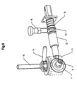
figure 5 représente une vue en perspective de l'ensemble constitué du porte-outil,de l'outil de coupe et de l'arbre d'entraînement en rotation dudit outil de coupe, dans une position dans laquelle l'outil de coupe est en position de coupe longitudinale ; - la
figure 6 représente une vue en perspective de l'ensemble formé du porte-outil, de l'outil de coupe et de l'arbre d'entraînement de l'outil de coupe dans une position dans laquelle l'outil de coupe est en position de coupe circulaire ; - la
figure 7 représente une vue en coupe de lafigure 6 et ; - la
figure 8 représente une vue en perspective de l'ensemble formé du porte-outil, de l'outil de coupe et de l'arbre d'entraînement en rotation de l'outil, ledit arbre étant en position débrayée.
- the
figure 1 represents a partial perspective view of an apparatus according to the invention; - the
figure 2 represents a sectional view of the apparatus shown infigure 1 in a position in which the cutting edge of the cutting tool extends flush with the passage housing of the elongated body formed by said jaws; - the
figure 3 represents a sectional view of the device of thefigure 1 in a position in which the cutting tool protrudes inside the housing formed by said jaws, so as to cut the constituent material of the elongate body to be cut, cut or strip; - the
figure 4 represents a partial perspective view of a device according to the invention; - the
figure 5 represents a perspective view of the assembly consisting of the tool holder, the cutting tool and the rotary drive shaft of said cutting tool, in a position in which the cutting tool is in the position of longitudinal section ; - the
figure 6 represents a perspective view of the assembly formed of the tool holder, the cutting tool and the drive shaft of the cutting tool in a position in which the cutting tool is in the cutting position circular; - the
figure 7 represents a sectional view of thefigure 6 and; - the
figure 8 is a perspective view of the assembly formed of the tool holder, the cutting tool and the drive shaft in rotation of the tool, said shaft being in the disengaged position.
Comme mentionné ci-dessus, l'appareil 1 objet de l'invention est plus particulièrement destiné à la découpe, l'entaille et/ou le dénudage au moins partiel d'un corps 2 allongé, tel qu'un câble multicouches concentriques, en particulier un câble électrique gainé, présentant en surface au moins une couche à découper, à entailler ou à dénuder.As mentioned above, the
De manière en soi connue, l'appareil 1 comprend au moins deux mâchoires 3, 4 délimitant un logement 5 de passage du corps 2 allongé, dans lequel ledit corps 2 est positionné axialement et au moins un porte-outil 6 à outil 7 de coupe circulaire rotatif. Dans les exemples représentés, les mâchoires 3 et 4 constitutives de l'appareil sont reliées l'une à l'autre par l'intermédiaire de tiges 21 le long desquelles les mâchoires peuvent coulisser, de manière à pouvoir être rapprochées ou écartées l'une de l'autre. En position rapprochée, lesdites mâchoires 3, 4 enserrent le corps 2 et maintiennent axialement ledit corps 2 à l'intérieur du logement 5 de passage, formé par l'espace laissé libre entre lesdites mâchoires 3, 4. L'une des mâchoires présente des moyens de centrage et d'appui du corps 2 allongé. Cette mâchoire, représentée en 4 aux figures, présente un profil transversal en V, les faces internes du V constituant la surface d'appui et de réception du corps 2 allongé. Ces faces internes sont formées par des rouleaux 23 montés libres à rotation. En regard des surfaces d'appui ménagées par la mâchoire 4, il est prévu une surface d'appui du corps 2 allongé ménagée sur la mâchoire 3. Dans ce cas, cette surface d'appui est formée par un train de galets 24, également montés libres en rotation sur ladite mâchoire 3.In a manner known per se, the
Grâce à la présence de ces surfaces d'appui à contact roulant, le corps 2 allongé est guidé axialement à l'intérieur du logement 5 de passage ménagé par lesdites mâchoires 3, 4, tout en pouvant se déplacer aisément axialement à l'intérieur dudit passage. L'axe longitudinal du corps 2 allongé correspond à l'axe dit longitudinal du logement 5 de passage.Thanks to the presence of these rolling contact bearing surfaces, the
L'outil 7 de coupe se présente sous forme d'un outil de coupe circulaire, rotatif, en l'occurrence sous forme d'une lame circulaire rotative, positionné sur la mâchoire 3 entre deux trains de galets 24. Cet outil 7 de coupe est porté par un porte-outil 6 et est raccordé au dit porte-outil 6 par l'intermédiaire d'un tronçon d'axe représenté en 8 aux figures sur lequel la lame circulaire est montée fixe. Ce tronçon d'axe 8 qui est monté à rotation dans le porte-outil 6, est confondu avec l'axe D2 de rotation de l'outil 7 de coupe. De manière caractéristique à l'invention, à l'état stationnaire des mâchoires 3, 4, en particulier dans une position dans laquelle les mâchoires 3 et 4 sont rapprochées l'une de l'autre et enserrent le corps 2 allongé à découper, entailler ou dénuder en le maintenant positionné axialement à l'intérieur du logement 5 de passage délimité par lesdites mâchoires, l'outil 7 de coupe peut être entraîné en déplacement sans que les mâchoires 3, 4 ne bougent. Cet outil 7 de coupe peut ainsi être déplacé d'une part, entre une position (
Pour permettre le passage entre une position dans laquelle le tranchant 9 de l'outil 7 de coupe s'étend en retrait ou en affleurement dudit logement 5 et une position dans laquelle le tranchant 9 de l'outil 7 de coupe s'étend en saillie à l'intérieur dudit logement 5, l'outil 7 de coupe est animé d'un mouvement axial suivant un axe D1 orthogonal à l'axe D2 de rotation de l'outil 7 de coupe circulaire rotatif.To allow the passage between a position in which the
Dans les exemples représentés, le porte-outil 6 et l'outil 7 de coupe sont animés d'un mouvement axial suivant un axe D1 orthogonal à l'axe D2 de rotation de l'outil 7 de coupe circulaire rotatif.In the examples shown, the
Pour permettre l'obtention d'un tel déplacement, le porte-outil 6 est équipé d'un axe 10 fileté coopérant avec le taraudage 18 d'une poignée 16 de manoeuvre, montée, libre en rotation et fixe axialement sur une mâchoire 3, de manière à provoquer, lors d'un entraînement en rotation de la poignée 16, un déplacement axial du porte-outil 6 et de l'outil 7 de coupe associé. Dans les exemples représentés, la poignée 16 de manoeuvre est évidée et reçoit à l'intérieur de son évidement une noix 17 taraudée, le taraudage 18 de ladite noix coopérant avec le filetage de l'axe 10 solidaire en déplacement du porte-outil 6. Ainsi lors de l'entraînement en rotation de la poignée de manoeuvre 16, le porte outil 6 et l'outil 7 de coupe associé sont déplacés suivant un axe correspondant à l'axe longitudinal de rotation de la poignée 16, pour permettre au tranchant 9 de l'outil 7 de coupe, de pénétrer plus ou moins dans le logement 5 de passage du corps 2 allongé ménagé entre lesdites mâchoires, de manière à venir entailler ou découper plus ou moins le corps 2 allongé, logé à l'intérieur dudit passage de logement 5.To make it possible to obtain such a displacement, the
Pour le passage entre une position dite de coupe circulaire, dans laquelle le tranchant 9 de l'outil 7 de coupe est perpendiculaire à l'axe longitudinal du corps 2 allongé à inciser ou à trancher et une position de coupe longitudinale, dans laquelle le tranchant 9 de l'outil 7 de coupe est parallèle à l'axe longitudinal du corps 2 allongé à inciser ou à trancher, l'outil 7 de coupe est animé d'un mouvement de rotation autour d'un axe D3, perpendiculaire à l'axe D2 de rotation de l'outil 7 de coupe circulaire rotatif. Dans les exemples représentés l'axe D3, autour duquel l'outil 7 de coupe est entraîné en rotation au cours du passage d'une position de coupe à une autre, est confondu avec l'axe D1 le long duquel l'outil 7 de coupe est mobile axialement. Dans les exemples représentés, outil 7 de coupe et porte-outil 6 sont montés solidaires en déplacement pour le passage d'une position de coupe à une autre et sont animés d'un mouvement de rotation autour d'un axe D3, perpendiculaire à l'axe D2 de rotation de l'outil 7 de coupe circulaire rotatif.For the passage between a so-called circular cutting position, in which the
Cet entraînement en rotation de l'outil 7 de coupe et du porte-outil 6 associé, peut être obtenu de différentes manières qui seront décrites ci-après. En effet, l'outil 7 de coupe circulaire rotatif est, en position de coupe longitudinale, entraîné en rotation par un arbre rotatif, dit arbre 12 d'entraînement de l'outil 7. Cet arbre 12 est ici constitué par un arbre de manivelle à l'extrémité duquel est rapporté un levier coudé de manivelle, représenté en 19 aux figures. L'actionnement de la manivelle permet donc d'entraîner l'outil 7 de coupe autour de son axe D2 de rotation, la lame de coupe circulaire étant centrée sur cet axe de rotation. Bien évidemment cet entraînement en rotation aurait pu également être réalisé de manière automatique. Cet arbre 12 d'entraînement de l'outil 7 de coupe est un arbre, solidaire en déplacement de l'outil 7, lors du déplacement de l'outil 7 pour faire pénétrer plus ou moins le tranchant 9 de l'outil 7 dans le logement 5 de passage. En d'autres termes, l'arbre 12 d'entraînement de l'outil de coupe, est un arbre mobile suivant l'axe D1 ou, en d'autres termes, suivant une direction parallèle à la direction de déplacement des mâchoires dans le sens d'un rapprochement ou d'un écartement au cours du déplacement axial de l'outil 7 de coupe et du porte-outil 6 associé, pour permettre le passage de l'outil 7 de coupe d'une position dans laquelle il s'étend en retrait ou en affleurement du logement 5 à une position dans laquelle le tranchant 9 de l'outil 7 de coupe s'étend en saillie à l'intérieur dudit logement 5. Ainsi l'arbre 12 d'entraînement de l'outil 7 de coupe suit les déplacements axiaux de l'outil 7 de coupe et du porte-outil 6 associé. Arbre 12, outil 7 de coupe et porte-outil 6 associé forment donc un ensemble solidaire en déplacement suivant l'axe D1 qui correspond à la direction de déplacement des mâchoires dans le sens d'un rapprochement ou d'un écartement. Pour permettre un tel déplacement, on note que l'arbre 12 est logé à l'intérieur d'un palier d'arbre représenté en 20 aux figures. Le bloc porte-outil 6 est monté mobile en rotation autour de l'axe D3 par rapport au palier 20 d'arbre. Ce palier 20 d'arbre est conformé pour être monté libre et guidé en coulissement par l'intermédiaire de tiges raccordant le palier 20 d'arbre à la mâchoire 3. Ce palier 20 d'arbre est monté solidaire en translation du bloc porte-outil 6 suivant l'axe D1 de manière à permettre audit palier 20 d'arbre de suivre les déplacements axiaux du bloc porte-outil 6, de sorte que l'arbre 12 d'entraînement de l'outil 7 de coupe est toujours positionné en alignement avec l'outil 7 de coupe indépendamment du positionnement relatif de l'outil 7 de coupe par rapport à la mâchoire 3 qui porte ledit outil 7 de coupe. Ainsi le déplacement axial du porte-outil 6 et de l'outil 7 de coupe associé suivant D1 provoque, en parallèle, un déplacement du palier 20 de l'arbre 12 d'entraînement de l'outil de coupe suivant D1 et donc parallèlement un déplacement de l'arbre 12 d'entraînement en rotation de l'outil 7 de coupe. Cet arbre 12 d'entraînement de l'outil 7 de coupe est par ailleurs, un arbre débrayable apte à passer d'une position débrayée, conforme à celle représentée à la
Comme l'illustre la
Enfin l'appareil 1 peut encore comporter des moyens d'ajustement du déplacement de l'outil 7 de coupe entre une position dans laquelle le tranchant 9 de l'outil 7 de coupe s'étend en retrait ou en affleurement du logement 5, et une position dans laquelle le tranchant 9 de l'outil 7 de coupe s'étend en saillie à l'intérieur dudit logement 5. Ces moyens incluent un émetteur apte à émettre un signal auditif ou visuel lors d'un contact du tranchant 9 de l'outil 7 de coupe avec une couche conductrice du corps 2 allongé à dénuder, entailler ou découper. Il doit être noté que pour la réalisation d'une coupe circulaire, l'appareil et le corps 2 allongé à découper sont animés d'un mouvement relatif de rotation. Pour la réalisation d'une coupe longitudinale, l'appareil 1 et le corps 2 allongé sont animés d'un mouvement relatif de translation, le corps 2 allongé, tendant à se déplacer axialement à l'intérieur dudit passage au fur et à mesure de l'entraînement en rotation de l'outil 7 de coupe circulaire autour de son axe D2.Finally, the
Le fonctionnement d'un tel appareil 1 est le suivant : dans un premier temps les mâchoires 3 et 4 sont écartées l'une de l'autre pour permettre le positionnement du corps 2 allongé à découper, à entailler, ou à dénuder, à l'intérieur du logement 5 de passage ménagé entre les surfaces d'appui desdites mâchoires. Une fois le corps 2 allongé introduit dans ledit passage et disposé axialement dans ce dernier, les mâchoires 3 et 4 sont rapprochées l'une de l'autre et immobilisées dans une position dans laquelle elles enserrent le corps 2 allongé. Dans cette position le tranchant 9 de l'outil 7 de coupe s'étend en retrait ou en affleurement du logement 5. L'outil 7 de coupe est alors positionné dans la position de coupe à effectuer. On débute généralement par une coupe longitudinale. L'outil 7 de coupe est donc déplacé par la rotation de la poignée 16 de manoeuvre pour pénétrer dans ledit logement 5 et venir entailler, en particulier la matière constitutive de la surface du corps 2 allongé. Une fois le réglage de la profondeur de coupe opéré, cette profondeur de coupe étant fonction du niveau de pénétration du tranchant de l'outil 7 de coupe à l'intérieur dudit logement 5, l'opération de coupe proprement dite peut commencer. L'outil 7 de coupe est alors entraîné en rotation par l'arbre 12 à l'aide de la manivelle 19, l'arbre 12 étant en prise directe avec l'outil 7 de coupe. Lorsque la coupe longitudinale est achevée, l'outil 7 de coupe est retiré du passage 5 par déplacement axial à l'aide de la poignée 16 de manoeuvre. L'arbre 12 d'entraînement est amené en position débrayée et l'outil 7 de coupe est déplacé depuis sa position de coupe longitudinale à sa position de coupe circulaire, soit par l'intermédiaire de la poignée 16 de manoeuvre, soit par l'intermédiaire de la poignée 11 de manoeuvre supplémentaire. L'arbre 12 d'entraînement est ensuite ramené en position embrayée dans laquelle il vient en prise avec le porte-outil 6 pour immobiliser ce dernier. La coupe circulaire peut alors commencer. A cet effet, le corps 2 allongé et l'appareil sont animés d'un déplacement relatif en rotation. Une fois la coupe circulaire achevée, les mâchoires 3 et 4 peuvent être écartées pour libérer le corps 2 allongé. On constate ainsi que les opérations de coupe longitudinale et circulaire ont pu être opérées sans déplacer les mâchoires 3 et 4 dans le sens d'un rapprochement ou d'un écartement afin d'éviter toute erreur de positionnement du corps lors du passage d'une position de coupe à une autre.The operation of such a
Claims (10)
caractérisé en ce que l'outil (7) de coupe est un outil (7) de coupe circulaire rotatif.Apparatus (1) for cutting, notching or at least partially stripping an elongated body (2), such as a multi-layer concentric cable, in particular a sheathed electrical cable, having on the surface at least one layer cutting, notching or stripping, said apparatus (1) and the elongated body (2) to be cut being driven at least in a relative rotational and / or translational movement, said apparatus (1) comprising at least two jaws (3, 4) delimiting a housing (5) for passage of the elongate body (2) in which said body (2) is positioned axially, and at least one tool holder (6) for cutting tool (7), this tool (7) of cutting, mounted movably on one (3) of the jaws (3, 4), being, in the stationary state of said jaws (3, 4), able to be driven in displacement on the one hand, between a position in the cutting edge (9) of the cutting tool (7) extends recessed or flush with said housing (5) and a position in which the trench the edge (9) of the cutting tool (7) extends projecting inside said housing (5), on the other hand, between a so-called circular cutting position in which the cutting edge (9) of the cutting tool (7) is orthogonal to the longitudinal axis of the elongate body (2) to be incised or sliced, and a so-called longitudinal cutting position in which the cutting edge (9) of the cutting tool (7) is parallel at the longitudinal axis of the elongate body (2),
characterized in that the cutting tool (7) is a rotary circular cutting tool (7).
caractérisé en ce que l'outil (7) de coupe circulaire rotatif est, en position de coupe longitudinale, entraîné en rotation par un arbre rotatif dit arbre (12) d'entraînement de l'outil (7), tel qu'un arbre de manivelle, cet arbre (12) étant, avec le porte-outil (6) et l'outil (7) de coupe, monté, à l'état stationnaire des mâchoires (3, 4), mobile suivant un axe (D1) orthogonal à l'axe (D2) de rotation de l'outil (7) de coupe pour le passage de l'outil (7) de coupe d'une position dans laquelle le tranchant (9) de l'outil (7) de coupe s'étend en retrait ou en affleurement dudit logement (5) à une position dans laquelle le tranchant (9) de l'outil (7) de coupe s'étend en saillie à l'intérieur dudit logement (5) et inversement, cet arbre (12) rotatif étant en outre un arbre débrayable, mobile axialement suivant une direction parallèle à l'axe de rotation dudit arbre entre une position débrayée dans laquelle le porte-outil (6) et l'outil (7) de coupe sont montés, indépendamment de l'arbre (12), mobiles en déplacement angulaire autour d'un axe (D3) perpendiculaire à l'axe (D2) de rotation de l'organe (7) de coupe pour le passage d'une position de coupe à une autre, et une position embrayée dans laquelle l'arbre (12) est en prise, avec le porte-outil (6), en position de coupe circulaire dudit outil (7) de coupe, et avec l'outil (7) de coupe, en position de coupe longitudinale dudit outil (7) de coupe.Apparatus (1) for cutting according to claim 1,
characterized in that the rotary circular cutting tool (7) is, in the longitudinal cutting position, rotated by a rotary shaft, said shaft (12) for driving the tool (7), such as a shaft with the tool holder (6) and the cutting tool (7), said shaft (12) being mounted in the stationary state of the jaws (3, 4), movable along an axis (D1) orthogonal to the axis (D2) of rotation of the cutting tool (7) for the passage of the cutting tool (7) from a position in which the cutting edge (9) of the tool (7) of section extends recessed or flush from said housing (5) to a position in which the cutting edge (9) of the cutting tool (7) projects into said housing (5) and conversely, this rotating shaft (12) is furthermore a disengageable shaft, axially movable in a direction parallel to the axis of rotation of said shaft between a disengaged position in which the tool holder (6) and the tool (7) of section are mounted, independently of the shaft (12), movable in angular displacement about an axis (D3) perpendicular to the axis (D2) of rotation of the cutting member (7) for the passage of a cutting position to another, and an engaged position in which the shaft (12) is engaged, with the tool holder (6), in the circular cutting position of said cutting tool (7), and with the tool (7) cutting, in longitudinal cutting position of said cutting tool (7).
caractérisé en ce que, en position embrayée, l'arbre (12) rotatif forme un verrouillage en déplacement angulaire du porte-outil (6) et de l'organe (7) de coupe autour de l'axe (D3) perpendiculaire à l'axe (D2) de rotation de l'outil (7) de coupe circulaire rotatif, et un organe de retenue du porte-outil (7) et de l'organe (6) de coupe dans la position de coupe choisie.Apparatus (1) for cutting according to Claim 2,
characterized in that , in the engaged position, the rotatable shaft (12) forms a latch in angular displacement of the tool holder (6) and the cutting member (7) about the axis (D3) perpendicular to the rotation axis (D2) of the rotary circular cutting tool (7), and a retaining member of the tool holder (7) and the cutting member (6) in the selected cutting position.
caractérisé en ce que l'arbre (12) d'entraînement en rotation de l'outil (7) de coupe est rappelé en position embrayée et est immobilisé axialement par l'intermédiaire d'un organe (15) de verrouillage radial audit arbre (12).Apparatus (1) for cutting according to one of claims 2 and 3,
characterized in that the shaft (12) for rotating the cutting tool (7) is returned to the engaged position and immobilized axially by means of a radial locking member (15) to said shaft ( 12).
caractérisé en ce que l'organe (15) de verrouillage de l'arbre (12) d'entraînement vient se loger dans une gorge (13) annulaire dudit arbre (12) d'entraînement.Apparatus (1) for cutting according to Claim 4,
characterized in that the member (15) for locking the drive shaft (12) is housed in an annular groove (13) of said drive shaft (12).
caractérisé en ce que l'appareil (1) comporte une poignée (16) de manoeuvre montée libre en rotation et fixe axialement sur une mâchoire (3), poignée (16) de manoeuvre et porte-outil (6) étant équipés l'un d'un taraudage (18), l'autre d'un axe (10) fileté, coopérant entre eux de manière à provoquer, en position embrayée de l'arbre (12) d'entraînement en rotation de l'outil (7) de coupe, un déplacement axial du porte-outil (6), de l'outil (7) de coupe et de l'arbre (12) d'entraînement en rotation de l'outil de coupe suivant l'axe (D1) perpendiculaire à l'axe (D2) de rotation de l'outil (7) de coupe.Apparatus (1) for cutting according to one of claims 2 to 5,
characterized in that the apparatus (1) comprises a handle (16) rotatably mounted and fixed axially on a jaw (3), handle (16) for operation and tool holder (6) being equipped with one a tapping (18), the other of a threaded axis (10) cooperating with each other so as to cause, in the engaged position of the shaft (12) for rotating the tool (7) cutting, a axial displacement of the tool holder (6), the cutting tool (7) and the shaft (12) for rotating the cutting tool along the axis (D1) perpendicular to the axis (D2) of rotation of the cutting tool (7).
caractérisé en ce que la poignée (16) de manoeuvre est un organe de commande polyvalent asservi à la position embrayée/débrayée de l'arbre (12) d'entraînement en rotation de l'outil (7) de coupe, ladite poignée (16) de manoeuvre formant, en position embrayée de l'arbre (12), un organe de commande d'entraînement en déplacement axial du porte-outil (6), de l'outil (7) de coupe et de l'arbre (12) suivant l'axe (D1) perpendiculaire à l'axe (D2) de rotation de l'outil (7) de coupe et, en position débrayée de l'arbre (12), un organe de commande en déplacement angulaire du porte-outil (6) et de l'outil (7) de coupe autour d'un axe (D3) perpendiculaire à l'axe (D2) de rotation de l'outil (7) de coupe.Apparatus (1) for cutting according to Claim 6,
characterized in that the operating handle (16) is a multipurpose control member slaved to the engaged / disengaged position of the rotary drive shaft (12) of the cutting tool (7), said handle (16) ) in the engaged position of the shaft (12) forming a drive control member in axial displacement of the tool holder (6), the cutting tool (7) and the shaft (12). ) along the axis (D1) perpendicular to the axis (D2) of rotation of the cutting tool (7) and, in the disengaged position of the shaft (12), a control member in angular displacement of the holder tool (6) and the tool (7) cutting around an axis (D3) perpendicular to the axis (D2) of rotation of the cutting tool (7).
caractérisé en ce que le porte-outil (6) est équipé, pour le passage de l'outil (7) de coupe et du porte-outil (6) associé d'une position de coupe à une autre, d'une poignée (11) de manoeuvre supplémentaire radiale à l'axe (10) fileté équipant le porte-outil (6).Apparatus (1) for cutting according to Claim 6,
characterized in that the tool holder (6) is equipped, for the passage of the cutting tool (7) and the associated tool holder (6) from one cutting position to another, with a handle ( 11) additional radial maneuver to the axis (10) threaded equipping the tool holder (6).
caractérisé en ce que, pour le passage entre une position dans laquelle le tranchant (9) de l'outil (7) de coupe s'étend en retrait ou en affleurement dudit logement (5) et une position dans laquelle le tranchant (9) de l'outil (7) de coupe s'étend en saillie à l'intérieur dudit logement (5), l'outil (7) de coupe est animé d'un mouvement axial suivant un axe (D1) orthogonal à l'axe (D2) de rotation de l'outil (7) de coupe circulaire rotatif et en ce que, pour le passage entre une position de coupe circulaire dans laquelle le tranchant (9) de l'outil (7) de coupe est perpendiculaire à l'axe longitudinal du corps (2) allongé à inciser ou à trancher, et une position de coupe longitudinale dans laquelle le tranchant (9) de l'outil de coupe est parallèle à l'axe longitudinal du corps (2) allongé à inciser ou à trancher, l'outil (7) de coupe est animé d'un mouvement de rotation autour d'un axe (D3) perpendiculaire à l'axe (D2) de rotation de l'outil (7) de coupe circulaire rotatif.Apparatus (1) for cutting according to one of claims 1 to 8,
characterized in that for the passage between a position in which the cutting edge (9) of the cutting tool (7) extends recessed or flush with said housing (5) and a position in which the cutting edge (9) of the cutting tool (7) protrudes inside said housing (5), the cutting tool (7) is driven axially along an axis (D1) orthogonal to the axis (D2) of rotation of the rotary circular cutting tool (7) and that , for the passage between a circular cutting position in which the cutting edge (9) of the cutting tool (7) is perpendicular to the longitudinal axis of the elongated body (2) to be cut or sliced, and a longitudinal cutting position in which the cutting edge (9) of the cutting tool is parallel to the longitudinal axis of the elongate body (2) incising or slicing, the cutting tool (7) is rotated about an axis (D3) perpendicular to the axis (D2) of rotation of the rotary circular cutter tool (7) .
caractérisé en ce que l'axe (D3) autour duquel l'outil (7) de coupe est entraîné en rotation au cours du passage d'une position de coupe à une autre est confondu avec l'axe (D1) le long duquel l'outil (7) de coupe est mobile axialement.Apparatus (1) for cutting according to claim 9,
characterized in that the axis (D3) about which the cutting tool (7) is rotated during the passage from one cutting position to another is coincident with the axis (D1) along which the cutting tool (7) is axially movable.
Applications Claiming Priority (1)
| Application Number | Priority Date | Filing Date | Title |
|---|---|---|---|
| FR0700649A FR2911811B1 (en) | 2007-01-31 | 2007-01-31 | APPARATUS FOR CUTTING AN EXTENDED BODY, SUCH AS A CONCENTRIC MULTILAYER CABLE. |
Publications (2)
| Publication Number | Publication Date |
|---|---|
| EP1953884A1 true EP1953884A1 (en) | 2008-08-06 |
| EP1953884B1 EP1953884B1 (en) | 2011-07-27 |
Family
ID=38461016
Family Applications (1)
| Application Number | Title | Priority Date | Filing Date |
|---|---|---|---|
| EP08290084A Active EP1953884B1 (en) | 2007-01-31 | 2008-01-30 | Device for cutting an elongated body such as a cable with multiple concentric layers |
Country Status (3)
| Country | Link |
|---|---|
| EP (1) | EP1953884B1 (en) |
| AT (1) | ATE518285T1 (en) |
| FR (1) | FR2911811B1 (en) |
Cited By (3)
| Publication number | Priority date | Publication date | Assignee | Title |
|---|---|---|---|---|
| ES2335737A1 (en) * | 2009-12-23 | 2010-03-31 | Jersalas S.L. | Cable peeler (Machine-translation by Google Translate, not legally binding) |
| ITBZ20090010A1 (en) * | 2009-03-26 | 2010-09-27 | Intercable Srl | CABLE MOLDING TOOL |
| WO2020124081A1 (en) * | 2018-12-14 | 2020-06-18 | Ripley Tools, Llc | Cable stripping tool |
Families Citing this family (1)
| Publication number | Priority date | Publication date | Assignee | Title |
|---|---|---|---|---|
| CN105680378B (en) * | 2016-04-25 | 2019-01-04 | 兴化市永盛电力器材有限公司 | A kind of adjustable cable peeler and its working method |
Citations (4)
| Publication number | Priority date | Publication date | Assignee | Title |
|---|---|---|---|---|
| US3216110A (en) | 1963-06-14 | 1965-11-09 | Douglas S Stallings | Operating heads for insulation strippers |
| US3722092A (en) | 1971-09-27 | 1973-03-27 | Bell Canada Northern Electric | Cable sheath cutting apparatus |
| EP0524121A1 (en) * | 1991-07-19 | 1993-01-20 | AEROSPATIALE Société Nationale Industrielle | Stripping device for the surface of a conductor covered with an insulating or protecting layer |
| US6308417B1 (en) | 1999-12-16 | 2001-10-30 | Lucien C. Ducret | Tool for separating and removing cable jackets and insulation from cables |
-
2007
- 2007-01-31 FR FR0700649A patent/FR2911811B1/en not_active Expired - Fee Related
-
2008
- 2008-01-30 EP EP08290084A patent/EP1953884B1/en active Active
- 2008-01-30 AT AT08290084T patent/ATE518285T1/en not_active IP Right Cessation
Patent Citations (4)
| Publication number | Priority date | Publication date | Assignee | Title |
|---|---|---|---|---|
| US3216110A (en) | 1963-06-14 | 1965-11-09 | Douglas S Stallings | Operating heads for insulation strippers |
| US3722092A (en) | 1971-09-27 | 1973-03-27 | Bell Canada Northern Electric | Cable sheath cutting apparatus |
| EP0524121A1 (en) * | 1991-07-19 | 1993-01-20 | AEROSPATIALE Société Nationale Industrielle | Stripping device for the surface of a conductor covered with an insulating or protecting layer |
| US6308417B1 (en) | 1999-12-16 | 2001-10-30 | Lucien C. Ducret | Tool for separating and removing cable jackets and insulation from cables |
Cited By (5)
| Publication number | Priority date | Publication date | Assignee | Title |
|---|---|---|---|---|
| ITBZ20090010A1 (en) * | 2009-03-26 | 2010-09-27 | Intercable Srl | CABLE MOLDING TOOL |
| EP2234229A1 (en) * | 2009-03-26 | 2010-09-29 | Intercable Srl | Stripping tool for electrical cables |
| ES2335737A1 (en) * | 2009-12-23 | 2010-03-31 | Jersalas S.L. | Cable peeler (Machine-translation by Google Translate, not legally binding) |
| WO2020124081A1 (en) * | 2018-12-14 | 2020-06-18 | Ripley Tools, Llc | Cable stripping tool |
| US11435526B2 (en) | 2018-12-14 | 2022-09-06 | Ripley Tools, Llc | Cable stripping tool with offset roller system |
Also Published As
| Publication number | Publication date |
|---|---|
| FR2911811A1 (en) | 2008-08-01 |
| EP1953884B1 (en) | 2011-07-27 |
| ATE518285T1 (en) | 2011-08-15 |
| FR2911811B1 (en) | 2009-10-23 |
Similar Documents
| Publication | Publication Date | Title |
|---|---|---|
| FR2954916A3 (en) | MOTORIZED TOOL | |
| EP1953884B1 (en) | Device for cutting an elongated body such as a cable with multiple concentric layers | |
| EP2300113A2 (en) | Portable device for sharpening the edges of a ski | |
| FR2992109A3 (en) | ELECTRICIAN FOLDING BLADE TOOL FOR STRIPPING AN ELECTRICAL CONDUCTOR | |
| FR2679391A1 (en) | DEVICE FOR LOADING THE SURFACE OF AN ELECTRICALLY CONDUCTIVE MATERIAL ELEMENT COVERED WITH A PROTECTIVE OR INSULATING ELEMENT SUCH AS A FILM, SHEATH OR THE LIKE. | |
| FR2992110A3 (en) | TOOL FOR STRIPPING ELECTRIC CABLES | |
| EP2500137B1 (en) | Rapid clamping pin | |
| EP1574285B1 (en) | Controlling device for two seperate bar feeding mechanisms | |
| EP3600736B1 (en) | Clamping chuck with inclined slides | |
| EP0869858B1 (en) | Machining unit with rotating head | |
| FR2900080A1 (en) | PROFILE TRACKING DEVICE FOR MACHINING A TUBULAR MEMBER | |
| CA1107946A (en) | Refacing tool for valve seats | |
| FR2602922A1 (en) | Tool for cutting off an outer covering of a cable, especially an electrical cable | |
| EP1846997B1 (en) | Stripping tool for tubular element | |
| EP0273781B1 (en) | Tool to prepare an electrical cable | |
| FR2958195A1 (en) | Orbital machining apparatus for machining e.g. cutting, tubular unit i.e. tube, has fixed support, locking plate and support arrangement that are formed of stacked sheets cut with laser while having realizing units to realize functions | |
| EP3967465B1 (en) | Bread slicer with a support for slices | |
| EP4084922B1 (en) | Electrospindle with integrated feed with automatic tool holder change | |
| KR101781592B1 (en) | pipe cutter | |
| WO2007063197A1 (en) | Cutting tool and apparatus for cutting lengthwise a protective sheath surrounding at least two cables | |
| EP1517422A1 (en) | Cable jacket stripping tool | |
| FR2660547A1 (en) | Surgical apparatus for making a conical cut in the cornea | |
| FR2992108A1 (en) | IMPROVED MANUAL TOOL FOR CABLE STRIPPING | |
| FR2914574A1 (en) | Tube cutting or recutting device for manufacturing e.g. packaging box, has inner blade e.g. chamfering blade, housed in cutting mandrel, and radially displaceable in peripheral opening provided in cutting mandrel | |
| FR3065331A1 (en) | CUTTING APPARATUS, ESPECIALLY FOR BENDING AN EXTENDED PART OF AN EXCELLENT PREDETERMINED CROSS SECTION, SUCH AS A MULTILAYER CABLE |
Legal Events
| Date | Code | Title | Description |
|---|---|---|---|
| PUAI | Public reference made under article 153(3) epc to a published international application that has entered the european phase |
Free format text: ORIGINAL CODE: 0009012 |
|
| AK | Designated contracting states |
Kind code of ref document: A1 Designated state(s): AT BE BG CH CY CZ DE DK EE ES FI FR GB GR HR HU IE IS IT LI LT LU LV MC MT NL NO PL PT RO SE SI SK TR |
|
| AX | Request for extension of the european patent |
Extension state: AL BA MK RS |
|
| 17P | Request for examination filed |
Effective date: 20090204 |
|
| 17Q | First examination report despatched |
Effective date: 20090309 |
|
| AKX | Designation fees paid |
Designated state(s): AT BE BG CH CY CZ DE DK EE ES FI FR GB GR HR HU IE IS IT LI LT LU LV MC MT NL NO PL PT RO SE SI SK TR |
|
| GRAP | Despatch of communication of intention to grant a patent |
Free format text: ORIGINAL CODE: EPIDOSNIGR1 |
|
| GRAS | Grant fee paid |
Free format text: ORIGINAL CODE: EPIDOSNIGR3 |
|
| GRAA | (expected) grant |
Free format text: ORIGINAL CODE: 0009210 |
|
| AK | Designated contracting states |
Kind code of ref document: B1 Designated state(s): AT BE BG CH CY CZ DE DK EE ES FI FR GB GR HR HU IE IS IT LI LT LU LV MC MT NL NO PL PT RO SE SI SK TR |
|
| REG | Reference to a national code |
Ref country code: GB Ref legal event code: FG4D Free format text: NOT ENGLISH |
|
| REG | Reference to a national code |
Ref country code: CH Ref legal event code: EP |
|
| REG | Reference to a national code |
Ref country code: DE Ref legal event code: R096 Ref document number: 602008008523 Country of ref document: DE Effective date: 20110929 |
|
| REG | Reference to a national code |
Ref country code: NL Ref legal event code: VDEP Effective date: 20110727 |
|
| REG | Reference to a national code |
Ref country code: AT Ref legal event code: MK05 Ref document number: 518285 Country of ref document: AT Kind code of ref document: T Effective date: 20110727 |
|
| PG25 | Lapsed in a contracting state [announced via postgrant information from national office to epo] |
Ref country code: FI Free format text: LAPSE BECAUSE OF FAILURE TO SUBMIT A TRANSLATION OF THE DESCRIPTION OR TO PAY THE FEE WITHIN THE PRESCRIBED TIME-LIMIT Effective date: 20110727 Ref country code: LT Free format text: LAPSE BECAUSE OF FAILURE TO SUBMIT A TRANSLATION OF THE DESCRIPTION OR TO PAY THE FEE WITHIN THE PRESCRIBED TIME-LIMIT Effective date: 20110727 Ref country code: IS Free format text: LAPSE BECAUSE OF FAILURE TO SUBMIT A TRANSLATION OF THE DESCRIPTION OR TO PAY THE FEE WITHIN THE PRESCRIBED TIME-LIMIT Effective date: 20111127 Ref country code: HR Free format text: LAPSE BECAUSE OF FAILURE TO SUBMIT A TRANSLATION OF THE DESCRIPTION OR TO PAY THE FEE WITHIN THE PRESCRIBED TIME-LIMIT Effective date: 20110727 Ref country code: SE Free format text: LAPSE BECAUSE OF FAILURE TO SUBMIT A TRANSLATION OF THE DESCRIPTION OR TO PAY THE FEE WITHIN THE PRESCRIBED TIME-LIMIT Effective date: 20110727 Ref country code: NL Free format text: LAPSE BECAUSE OF FAILURE TO SUBMIT A TRANSLATION OF THE DESCRIPTION OR TO PAY THE FEE WITHIN THE PRESCRIBED TIME-LIMIT Effective date: 20110727 Ref country code: PT Free format text: LAPSE BECAUSE OF FAILURE TO SUBMIT A TRANSLATION OF THE DESCRIPTION OR TO PAY THE FEE WITHIN THE PRESCRIBED TIME-LIMIT Effective date: 20111128 Ref country code: NO Free format text: LAPSE BECAUSE OF FAILURE TO SUBMIT A TRANSLATION OF THE DESCRIPTION OR TO PAY THE FEE WITHIN THE PRESCRIBED TIME-LIMIT Effective date: 20111027 |
|
| PG25 | Lapsed in a contracting state [announced via postgrant information from national office to epo] |
Ref country code: CY Free format text: LAPSE BECAUSE OF FAILURE TO SUBMIT A TRANSLATION OF THE DESCRIPTION OR TO PAY THE FEE WITHIN THE PRESCRIBED TIME-LIMIT Effective date: 20110727 Ref country code: LV Free format text: LAPSE BECAUSE OF FAILURE TO SUBMIT A TRANSLATION OF THE DESCRIPTION OR TO PAY THE FEE WITHIN THE PRESCRIBED TIME-LIMIT Effective date: 20110727 Ref country code: AT Free format text: LAPSE BECAUSE OF FAILURE TO SUBMIT A TRANSLATION OF THE DESCRIPTION OR TO PAY THE FEE WITHIN THE PRESCRIBED TIME-LIMIT Effective date: 20110727 Ref country code: SI Free format text: LAPSE BECAUSE OF FAILURE TO SUBMIT A TRANSLATION OF THE DESCRIPTION OR TO PAY THE FEE WITHIN THE PRESCRIBED TIME-LIMIT Effective date: 20110727 Ref country code: PL Free format text: LAPSE BECAUSE OF FAILURE TO SUBMIT A TRANSLATION OF THE DESCRIPTION OR TO PAY THE FEE WITHIN THE PRESCRIBED TIME-LIMIT Effective date: 20110727 Ref country code: GR Free format text: LAPSE BECAUSE OF FAILURE TO SUBMIT A TRANSLATION OF THE DESCRIPTION OR TO PAY THE FEE WITHIN THE PRESCRIBED TIME-LIMIT Effective date: 20111028 |
|
| REG | Reference to a national code |
Ref country code: IE Ref legal event code: FD4D |
|
| PG25 | Lapsed in a contracting state [announced via postgrant information from national office to epo] |
Ref country code: SK Free format text: LAPSE BECAUSE OF FAILURE TO SUBMIT A TRANSLATION OF THE DESCRIPTION OR TO PAY THE FEE WITHIN THE PRESCRIBED TIME-LIMIT Effective date: 20110727 Ref country code: IE Free format text: LAPSE BECAUSE OF FAILURE TO SUBMIT A TRANSLATION OF THE DESCRIPTION OR TO PAY THE FEE WITHIN THE PRESCRIBED TIME-LIMIT Effective date: 20110727 Ref country code: CZ Free format text: LAPSE BECAUSE OF FAILURE TO SUBMIT A TRANSLATION OF THE DESCRIPTION OR TO PAY THE FEE WITHIN THE PRESCRIBED TIME-LIMIT Effective date: 20110727 |
|
| PG25 | Lapsed in a contracting state [announced via postgrant information from national office to epo] |
Ref country code: EE Free format text: LAPSE BECAUSE OF FAILURE TO SUBMIT A TRANSLATION OF THE DESCRIPTION OR TO PAY THE FEE WITHIN THE PRESCRIBED TIME-LIMIT Effective date: 20110727 Ref country code: IT Free format text: LAPSE BECAUSE OF FAILURE TO SUBMIT A TRANSLATION OF THE DESCRIPTION OR TO PAY THE FEE WITHIN THE PRESCRIBED TIME-LIMIT Effective date: 20110727 Ref country code: RO Free format text: LAPSE BECAUSE OF FAILURE TO SUBMIT A TRANSLATION OF THE DESCRIPTION OR TO PAY THE FEE WITHIN THE PRESCRIBED TIME-LIMIT Effective date: 20110727 |
|
| PLBE | No opposition filed within time limit |
Free format text: ORIGINAL CODE: 0009261 |
|
| STAA | Information on the status of an ep patent application or granted ep patent |
Free format text: STATUS: NO OPPOSITION FILED WITHIN TIME LIMIT |
|
| PG25 | Lapsed in a contracting state [announced via postgrant information from national office to epo] |
Ref country code: DK Free format text: LAPSE BECAUSE OF FAILURE TO SUBMIT A TRANSLATION OF THE DESCRIPTION OR TO PAY THE FEE WITHIN THE PRESCRIBED TIME-LIMIT Effective date: 20110727 |
|
| 26N | No opposition filed |
Effective date: 20120502 |
|
| BERE | Be: lapsed |
Owner name: ROUX, DIDIER Effective date: 20120131 |
|
| REG | Reference to a national code |
Ref country code: DE Ref legal event code: R097 Ref document number: 602008008523 Country of ref document: DE Effective date: 20120502 |
|
| PG25 | Lapsed in a contracting state [announced via postgrant information from national office to epo] |
Ref country code: MC Free format text: LAPSE BECAUSE OF NON-PAYMENT OF DUE FEES Effective date: 20120131 |
|
| REG | Reference to a national code |
Ref country code: CH Ref legal event code: PL |
|
| GBPC | Gb: european patent ceased through non-payment of renewal fee |
Effective date: 20120130 |
|
| PG25 | Lapsed in a contracting state [announced via postgrant information from national office to epo] |
Ref country code: LI Free format text: LAPSE BECAUSE OF NON-PAYMENT OF DUE FEES Effective date: 20120131 Ref country code: CH Free format text: LAPSE BECAUSE OF NON-PAYMENT OF DUE FEES Effective date: 20120131 Ref country code: DE Free format text: LAPSE BECAUSE OF NON-PAYMENT OF DUE FEES Effective date: 20120801 Ref country code: GB Free format text: LAPSE BECAUSE OF NON-PAYMENT OF DUE FEES Effective date: 20120130 |
|
| REG | Reference to a national code |
Ref country code: DE Ref legal event code: R119 Ref document number: 602008008523 Country of ref document: DE Effective date: 20120801 |
|
| PG25 | Lapsed in a contracting state [announced via postgrant information from national office to epo] |
Ref country code: BE Free format text: LAPSE BECAUSE OF NON-PAYMENT OF DUE FEES Effective date: 20120131 |
|
| PG25 | Lapsed in a contracting state [announced via postgrant information from national office to epo] |
Ref country code: ES Free format text: LAPSE BECAUSE OF FAILURE TO SUBMIT A TRANSLATION OF THE DESCRIPTION OR TO PAY THE FEE WITHIN THE PRESCRIBED TIME-LIMIT Effective date: 20111107 |
|
| PG25 | Lapsed in a contracting state [announced via postgrant information from national office to epo] |
Ref country code: BG Free format text: LAPSE BECAUSE OF FAILURE TO SUBMIT A TRANSLATION OF THE DESCRIPTION OR TO PAY THE FEE WITHIN THE PRESCRIBED TIME-LIMIT Effective date: 20111027 |
|
| PG25 | Lapsed in a contracting state [announced via postgrant information from national office to epo] |
Ref country code: MT Free format text: LAPSE BECAUSE OF FAILURE TO SUBMIT A TRANSLATION OF THE DESCRIPTION OR TO PAY THE FEE WITHIN THE PRESCRIBED TIME-LIMIT Effective date: 20110727 |
|
| PG25 | Lapsed in a contracting state [announced via postgrant information from national office to epo] |
Ref country code: TR Free format text: LAPSE BECAUSE OF FAILURE TO SUBMIT A TRANSLATION OF THE DESCRIPTION OR TO PAY THE FEE WITHIN THE PRESCRIBED TIME-LIMIT Effective date: 20110727 |
|
| PG25 | Lapsed in a contracting state [announced via postgrant information from national office to epo] |
Ref country code: LU Free format text: LAPSE BECAUSE OF NON-PAYMENT OF DUE FEES Effective date: 20120130 |
|
| PG25 | Lapsed in a contracting state [announced via postgrant information from national office to epo] |
Ref country code: HU Free format text: LAPSE BECAUSE OF FAILURE TO SUBMIT A TRANSLATION OF THE DESCRIPTION OR TO PAY THE FEE WITHIN THE PRESCRIBED TIME-LIMIT Effective date: 20080130 |
|
| REG | Reference to a national code |
Ref country code: FR Ref legal event code: PLFP Year of fee payment: 9 |
|
| REG | Reference to a national code |
Ref country code: FR Ref legal event code: PLFP Year of fee payment: 10 |
|
| REG | Reference to a national code |
Ref country code: FR Ref legal event code: PLFP Year of fee payment: 11 |
|
| PGFP | Annual fee paid to national office [announced via postgrant information from national office to epo] |
Ref country code: FR Payment date: 20230124 Year of fee payment: 16 |