EP1953878A2 - Connecteur enfichable d'airbag étanche - Google Patents
Connecteur enfichable d'airbag étanche Download PDFInfo
- Publication number
- EP1953878A2 EP1953878A2 EP08001552A EP08001552A EP1953878A2 EP 1953878 A2 EP1953878 A2 EP 1953878A2 EP 08001552 A EP08001552 A EP 08001552A EP 08001552 A EP08001552 A EP 08001552A EP 1953878 A2 EP1953878 A2 EP 1953878A2
- Authority
- EP
- European Patent Office
- Prior art keywords
- connector
- plug
- contact
- elements
- fuse
- Prior art date
- Legal status (The legal status is an assumption and is not a legal conclusion. Google has not performed a legal analysis and makes no representation as to the accuracy of the status listed.)
- Granted
Links
- 238000000034 method Methods 0.000 claims abstract description 26
- 230000004913 activation Effects 0.000 claims abstract description 12
- 230000013011 mating Effects 0.000 claims description 26
- 238000007789 sealing Methods 0.000 claims description 17
- 230000003213 activating effect Effects 0.000 claims description 8
- 239000004020 conductor Substances 0.000 description 9
- 238000003780 insertion Methods 0.000 description 8
- 230000037431 insertion Effects 0.000 description 8
- 230000007613 environmental effect Effects 0.000 description 5
- 230000005494 condensation Effects 0.000 description 2
- 238000009833 condensation Methods 0.000 description 2
- 230000002411 adverse Effects 0.000 description 1
- 239000002131 composite material Substances 0.000 description 1
- 238000010276 construction Methods 0.000 description 1
- 230000009977 dual effect Effects 0.000 description 1
- 230000000694 effects Effects 0.000 description 1
- 230000007257 malfunction Effects 0.000 description 1
Images


Classifications
-
- H—ELECTRICITY
- H01—ELECTRIC ELEMENTS
- H01R—ELECTRICALLY-CONDUCTIVE CONNECTIONS; STRUCTURAL ASSOCIATIONS OF A PLURALITY OF MUTUALLY-INSULATED ELECTRICAL CONNECTING ELEMENTS; COUPLING DEVICES; CURRENT COLLECTORS
- H01R13/00—Details of coupling devices of the kinds covered by groups H01R12/70 or H01R24/00 - H01R33/00
- H01R13/66—Structural association with built-in electrical component
- H01R13/70—Structural association with built-in electrical component with built-in switch
- H01R13/701—Structural association with built-in electrical component with built-in switch the switch being actuated by an accessory, e.g. cover, locking member
-
- H—ELECTRICITY
- H01—ELECTRIC ELEMENTS
- H01R—ELECTRICALLY-CONDUCTIVE CONNECTIONS; STRUCTURAL ASSOCIATIONS OF A PLURALITY OF MUTUALLY-INSULATED ELECTRICAL CONNECTING ELEMENTS; COUPLING DEVICES; CURRENT COLLECTORS
- H01R13/00—Details of coupling devices of the kinds covered by groups H01R12/70 or H01R24/00 - H01R33/00
- H01R13/46—Bases; Cases
- H01R13/52—Dustproof, splashproof, drip-proof, waterproof, or flameproof cases
- H01R13/5219—Sealing means between coupling parts, e.g. interfacial seal
-
- H—ELECTRICITY
- H01—ELECTRIC ELEMENTS
- H01R—ELECTRICALLY-CONDUCTIVE CONNECTIONS; STRUCTURAL ASSOCIATIONS OF A PLURALITY OF MUTUALLY-INSULATED ELECTRICAL CONNECTING ELEMENTS; COUPLING DEVICES; CURRENT COLLECTORS
- H01R13/00—Details of coupling devices of the kinds covered by groups H01R12/70 or H01R24/00 - H01R33/00
- H01R13/62—Means for facilitating engagement or disengagement of coupling parts or for holding them in engagement
- H01R13/639—Additional means for holding or locking coupling parts together, after engagement, e.g. separate keylock, retainer strap
-
- H—ELECTRICITY
- H01—ELECTRIC ELEMENTS
- H01R—ELECTRICALLY-CONDUCTIVE CONNECTIONS; STRUCTURAL ASSOCIATIONS OF A PLURALITY OF MUTUALLY-INSULATED ELECTRICAL CONNECTING ELEMENTS; COUPLING DEVICES; CURRENT COLLECTORS
- H01R13/00—Details of coupling devices of the kinds covered by groups H01R12/70 or H01R24/00 - H01R33/00
- H01R13/66—Structural association with built-in electrical component
- H01R13/70—Structural association with built-in electrical component with built-in switch
- H01R13/703—Structural association with built-in electrical component with built-in switch operated by engagement or disengagement of coupling parts, e.g. dual-continuity coupling part
- H01R13/7031—Shorting, shunting or bussing of different terminals interrupted or effected on engagement of coupling part, e.g. for ESD protection, line continuity
- H01R13/7032—Shorting, shunting or bussing of different terminals interrupted or effected on engagement of coupling part, e.g. for ESD protection, line continuity making use of a separate bridging element directly cooperating with the terminals
-
- H—ELECTRICITY
- H01—ELECTRIC ELEMENTS
- H01R—ELECTRICALLY-CONDUCTIVE CONNECTIONS; STRUCTURAL ASSOCIATIONS OF A PLURALITY OF MUTUALLY-INSULATED ELECTRICAL CONNECTING ELEMENTS; COUPLING DEVICES; CURRENT COLLECTORS
- H01R13/00—Details of coupling devices of the kinds covered by groups H01R12/70 or H01R24/00 - H01R33/00
- H01R13/40—Securing contact members in or to a base or case; Insulating of contact members
- H01R13/42—Securing in a demountable manner
- H01R13/436—Securing a plurality of contact members by one locking piece or operation
- H01R13/4361—Insertion of locking piece perpendicular to direction of contact insertion
- H01R13/4362—Insertion of locking piece perpendicular to direction of contact insertion comprising a temporary and a final locking position
-
- H—ELECTRICITY
- H01—ELECTRIC ELEMENTS
- H01R—ELECTRICALLY-CONDUCTIVE CONNECTIONS; STRUCTURAL ASSOCIATIONS OF A PLURALITY OF MUTUALLY-INSULATED ELECTRICAL CONNECTING ELEMENTS; COUPLING DEVICES; CURRENT COLLECTORS
- H01R13/00—Details of coupling devices of the kinds covered by groups H01R12/70 or H01R24/00 - H01R33/00
- H01R13/64—Means for preventing incorrect coupling
- H01R13/641—Means for preventing incorrect coupling by indicating incorrect coupling; by indicating correct or full engagement
Definitions
- the invention relates to a connector for connecting an airbag, comprising at least one receiving housing, which includes a contact element, which is short-circuited by a short-circuiting means, with a plug fuse device having a protruding into the receiving housing activation member, wherein the short-circuiting means is separable from the contact element by the activation member ,
- the invention further relates to a method for mating a connector for an airbag connection, wherein at least one contact element is short-circuited in the interior of a receiving housing with a short-circuiting means, and a plug-in fuse is actuated, whereby an activating member separates the short-circuiting means from the contact element and activates the connector.
- Connectors for connecting airbags in motor vehicles are known.
- the electrically triggering igniter of the airbag is coupled with a connector to the trigger mechanism.
- connectors for an airbag connection usually have two plug elements which receive a multiplicity of contact elements.
- the contact elements are secured against removal by means of clamping aids provided for this purpose and by contact safeguards in the plug elements.
- the electrical connections of the ignition mechanism are usually short-circuited with a shorting bridge. This can avoid that the ignition mechanism unintentionally triggers by electrical interference during assembly.
- the connector elements are often provided after plugging together with plug-in protection devices that prevent a pulling apart of the connector. Ideally, this measure can be connected to the opening of the shorting bridge.
- Airbag system connectors must be very robust, as they are often exposed to adverse environmental conditions. You must shield the electrical connection of the airbag control against the interference of other components of the vehicle electronics and withstand vibration and moisture. Their complex construction, however, complicates their sealing and robust design.
- the invention is therefore an object of the invention to provide a connector that meets the safety requirements of airbag connector and at the same time keeps harmful environmental influences from its electrical contact.
- This simple solution has the advantage that the number and size of openings and other weak points in the housing of the composite can be kept low and the sealing of the connector is facilitated.
- a fastening portion of the plug-in fuse device can be plugged into a shaft outside of the receiving housing.
- This embodiment of the attachment of the plug-in fuse device has the advantage that the plug-in fuse device is protected in the shaft from harmful mechanical influences or manipulations.
- the connector has two connector elements, which form an interior at least in a final position.
- all the elements to be protected of the connector can be accommodated in the interior.
- Harmful or corrosive media can be better kept away from the functional components of the connector, if it is provided that the interior is sealed with a sealing element between the connector elements.
- the connector can then continue to be activated from the outside, if it is provided that the activation member protrudes at least in a securing position into a passage in the sealing element.
- the measures known in the state of the art for avoiding misconnections only detect individual components of a plug connection.
- the plug states of the elements of a connector can only be checked in separate sub-steps and not for the entire connection process. In order to avoid misleading, it is necessary that each mating process is checked. This includes both the insertion of the electrical conductors in the connector elements, as well as the mating of the connector elements.
- At least one contact fuse is designed as a test element and the connector elements each have a query range that forms in a pre-assembly the scholarorgan one of the connector elements lying in a direction of insertion before the final position stop for the interrogation of the other connector element and in that, in a final assembly position, the test member of one male member and the interrogation portion of the other male member are disengaged. This ensures that plug elements of the connector interrogate each other the plug state of their electrical conductors by they are only plugged together when the electrical conductors are properly plugged into the connector elements.
- the interior of the at least one contact element, at least one of the strigorgane and / or receives the at least one short-circuiting means are shielded from harmful environmental influences and protected from corrosive media, which may affect the function of the connector. It is advantageous if the sealed space has a small volume, so that the amount of air in the connector are small and a condensation is prevented.
- the at least one contact-securing device has at least one test element which, in the final assembly position, protrudes into at least one contact receptacle on the plug element.
- the contact fuses can be arranged according to a further, possible advantageous embodiment of the connector so that the at least one contact element is held in the final assembly position by at least one contact fuse in the at least one contact.
- This second function of the contact safety device has the advantage that the electrical contact elements are secured against being pulled out of the plug element.
- the at least one contact fuse is locked in the final assembly position with the plug element. Locking has two advantages: on the one hand confirming that the contact lock is in the final assembly position, on the other hand it keeps the contact-securing element on the plug element, which facilitates the assembly of the connector.
- the at least one contact has at least one clamping aid on which the contact element is held in the at least one contact.
- the contact element may have a latching means, which bears against the clamping aid and tensile forces acting counter to its insertion direction, receives. The engagement of the locking means on the clamping aid can also confirm the correct plug state of the contact element.
- the two plug elements are secured against being pulled apart in a closing position.
- the connector can be protected against unintentional opening.
- the plug elements have at least one latching opening, in which engages in the final position at least one latching lug.
- the engagement of the detent in the final position has the advantages that it holds the connector elements in the final position and at the same time confirms the reaching of the final position.
- the plug fuse device is assigned to a plug element and is designed to be movable by the other plug member from a holding position to a release position, wherein the plug fuse device is fixed in the holding position and from the release position can be converted into a securing position in which it is in locking engagement with at least one of the plug elements.
- the fixing of the plug-in fuse device in the holding position has the advantage that the plug-in fuse device must first be placed in a release position before it can be transferred to the securing position. As a result, the plug-in fuse can be attached to the connector during the entire assembly and can not inadvertently get into the securing position.
- the plug-in fuse device engages in the holding position on the plug connector, preferably on the latching opening.
- the fact that the plug-in fuse device engages at the same latching opening, which serves for locking the plug elements, the plug-in fuse device is only transferred from the holding position to the release position when the plug elements are in the final position.
- the plug-in fuse device can cover the latching opening in the securing position.
- the locking mechanism is thereby protected against environmental influences and unintentional opening.
- At least one plug element has a receiving housing, which accommodates with a receptacle at least one contact housing, which contains the at least one contact.
- At least one male element identifies at least one Ansteckelement and / or a locking member, by means of which the connector can be attached.
- the above object is inventively achieved in that the plug-in fuse device is moved outside along the receiving housing for activation.
- An inventive method for mating a connector can be advantageously supplemented by the fact that it is provided to seal the connector with a sealing element. As a result, the electrical contacts inside the connector are protected against harmful environmental influences.
- An inventive method for mating a connector can be advantageously supplemented by plugging the activation member at the latest when transferring into a securing position in a passage in the sealing element. As a result, the connector can be secured against opening and activated at the same time, without using additional sealing elements.
- Misjures can be avoided in a method according to the invention for mating a connector, if it is provided that with at least one contact fuse in a pre-assembly complete mating a connector is blocked.
- This method step allows the connector elements the mutual query of the plug states of their individual components. It prevents an incompletely assembled plug element from being connected to its counterpart, which would render the plug connector inoperable.
- An inventive method for mating a connector can be improved by providing at least one contact fuse to be provided with at least one test element and to allow the projecting at least one test element in a final assembly position in at least one contact on the male element. By protrude into the contact can be checked whether a correspondingly shaped contact element is inserted incorrectly in the contact. If this is the case, the contact protection does not reach the final assembly position and remains in a pre-assembly position.
- a contact fuse can fulfill a dual function if it is provided to hold at least one contact element insertable into the plug elements in the at least one contact with the at least one contact fuse in the final assembly position. This prevents that the contact element is inadvertently pulled out of contact.
- a contact safety device can be fastened to the plug element and its correct seat can be confirmed if it is provided to lock at least one of the contact safety devices in the final assembly position with the plug element.
- An inventive method for mating a connector can be improved by supporting the at least one contact element in the at least one contact on a clamping aid, and thus to keep the contact element in the at least one contact.
- the clamping aid can be used to lock the contact element on the connector element to ensure a secure fit of the contact element in the connector element and confirm.
- An inventive method for mating a connector can be improved according to the invention, if provided by the complete mating of the connector elements a locking lug on a connector element in to engage a detent opening on the other connector element and thereby secure the two connector elements against pulling.
- An inventive method for mating a connector may include fixing the plug fuse device in a holding position on a plug element and to solve the fixation by the complete mating of the connector elements, whereby the plug fuse device is set in a release position in which it is freely movable. As a result, the plug-in fuse device is also firmly connected to the connector when it is not in the final position. Thus, the plug-in fuse can not get lost during assembly of the connector.
- the method for mating a connector can be meaningfully supplemented by moving the plug-in fuse from the release position to a securing position to cover the latching mechanism. This can prevent unintentional opening of the latching mechanism.
- FIG. 1 shows a schematic perspective view of a plug element 2 designed according to the invention.
- the plug-in element 2 has a receiving housing 3 and a contact housing 4 and a contact fuse. 5
- the receiving housing 3 has a receptacle 6, which has a query area 7.
- Ansteck outcome 8 and a locking member 9 by means of which the receiving housing 3 can be mounted in its mounting environment.
- the contact housing 4 has contact receptacles 10 and short-circuiting means 11 which can briefly close contact elements 24 introduced into the contact receptacle 10 (not shown here).
- the contact housing 4 has snap-in aids 12.
- the latching aids 12 make it easier to secure the contact-securing device 5 to the contact housing 4.
- the contact security 5 has via latching hooks 13, which can engage behind the latching aids 12.
- the contact safety device 5 has a test element 14.
- Plug element 2 ' has a receiving housing 3', a contact housing 4 ', a contact fuse 5', a sealing element 19 and a plug-in fuse device 17.
- the contact housing 4 ' has a query area 7' and locking aids 12 '.
- the contact safety 5 ' has latching hook, test element 14' and a test element 16.
- the receiving housing 3 ' has a Ansteckelement 8'.
- the plug-in fuse device 17 has a detent spring 18 and an activating means 19. It also has a mounting portion 33. At this the plug-in fuse device 17 is held on the receiving housing 3 '.
- the attachment portion 33 is designed here as a carriage on which the plug-in fuse device 17 along the outside of the Steckerlements 2 'can be moved.
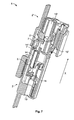
- Fig. 3 the two connector elements 2 and 2 'of a inventively designed connector 1 are shown.
- an electrical conductor 15 is inserted in the form of a pin contact.
- the contact receptacles 10 and 10 'in the contact housings 4 and 4' have clamping aids 21, by means of which a contact element 24 can be fastened more easily in the contact receptacles 10 and 10 '.
- the plug element 2 ' is provided with a sealing element 20 and the plug-in fuse device 17 is inserted into the plug element 2'. Its attachment portion 33 is seated in the shaft 32 outside the plug element 2 '.
- An actuation region 34 serves to displace the plug-in safety device 17 in the shaft 32.
- the actuation region 34 has recesses 35, by means of which a detent spring 18 can be actuated on the plug-in safety device 17 in the inserted state from outside with a tool.
- the detent spring 18 on the plug-in fuse device 17 is seated on a stop 22.
- the plug-in fuse device 17 is in a holding position (A), which prevents the plug-locking device 17 in a securing position (C) can be.
- the connector elements 2 and 2 ' are completely assembled and can be plugged together in a direction of insertion (X).
- Fig. 4 the two connector elements 2 and 2 'are shown in a position in which they can not be mated.
- the test element 16 'of the contact safety 5' does not protrude into the contact receptacle 10 'of the plug element 2'.
- the contact safety 5 ' is in a pre-assembly position (V).
- V pre-assembly
- Fig. 5 is a section of a perspective sectional view of the connector elements 2 and 2 'shown.
- the test element 14 'at the contact fuse 5' can pass through the interrogation region 7 on the plug element 2 because the test element 16 'protrudes at the contact protection 5' into the contact receptacle 10 'in the plug element 2'.
- the contact fuse 5 ' is thus in a final assembly position (E), in which the test element 14' in the insertion direction (X) is not blocked by the interrogation area 7.
- test element 16 on the contact safety device 5 does not protrude into the receptacle 6 on the plug element 2.
- the contact safety device 5 is in a preassembly position (V) and the test element 14 on the contact safety device 5 is removed from the interrogation region 7 'of the plug element 2' in the stretch direction (X ) blocked.
- FIG. 6 shows the connector elements 2 and 2 'without receiving housing 3 and 3'.
- the contact fuse 5 'on the plug element 2' is in a final assembly position (E).
- the latching hook 3 'on the latching aid 12' on the contact housing 4 ' is locked.
- the test element 5 of the plug element 2 in a pre-assembly position (V).
- the latching hook 13 is not locked with the locking aid 12.
- the plug elements 2 and 2 ' can not be plugged together in the plug-in direction (X), because the test element 14 is blocked at the contact fuse 5 by the interrogation region 7' of the plug element 2 '. If the contact fuse 5 in a final assembly position (E), the test element 14 could pass the interrogation area 7 'and the plug elements 2 and 2' could be put together.
- test elements 14 and 14 ' are preferably formed complementarily, whereby in the final position (S), the stability of the connector 1 is increased.
- FIG. 6 shows Fig. 6 the plug fuse device 17 in a holding position (A).
- a latching opening 27 on the plug element 2 'at the same time forms the stop 22 for the detent spring 18 on the plug-in safety device 17.
- the activating means 19 on the plug-in safety device 17 projects into a passage 25 on the sealing element 20 which tightly encloses the activating means 19 ,
- FIG. 7 an inventive ausgestalteter connector 1 is shown, in which the test elements 16 and 16 'of both contact fuses 5 and 5' in the receptacles 6 and 6 'on the connector elements 2 and 2' protrude.
- both contact fuses 5 and 5 ' are in the final assembly position (E).
- the test elements 14 and 14 'at the contact fuses 5 and 5' the interrogation areas 7 and 7 'of the connector elements 2 and 2' happen and the connector elements 2 and 2 'can be plugged together in the insertion direction (X).
- Fig. 8 are the two connector elements 2 and 2 'of the inventively designed connector 1 plugged together and are in the final position (S).
- a nose 26 on the plug element 2 is engaged in a latching opening 27 on the plug element 2 '.
- the nose 26 on the plug element 2 has pushed the detent spring 18 on the plug-in safety device 17 from the stop 22.
- the plug-in fuse device 17 is a release position (B), from which the plug-in fuse device (17) in a securing position (C) can be moved.
- FIG. 9 An inventively triedstaltete connector 1 in the final position (S) with the plug-in fuse device 17 in the securing position (C) is in Fig. 9 shown.
- the plug-in fuse 17 is seated on a further stop 22 'and engages behind the detent means 28 on the connector 1 simultaneously with the detent spring 18. As a result, the plug-in fuse device 17 is fixed to the connector 1.
- the latching opening 27 is protected against external mechanical effects and can not be manipulated as long as the plug-in fuse device 17 is in the securing position (C).
- the sealing element 20 also seals the connector 1.
- the contact receptacles 10 and 10 'on the connector elements 2 and 2' are closed results in a sealed space 30 in the connector 1.
- the sealed space 30 are any in the contacts 10 and 10 'plugged electrical conductors 15 and contact elements 24, the contact fuses 5 and 5 'and the short-circuiting means 11.
- Fig. 10 is a section of a schematic perspective view of a sectional view of an inventively designed connector 1 shown.
- an electrical conductor 15 is in contact with a contact element 24.
- the contact element 24 engages behind with a holding means 31, the clamping aid 21 and is thus secured against pulling out of the connector 1.
- the activation means 19 separates the short-circuiting means 11 from the contact element 24 and the connector 1 is activated.
- Fig. 11 shows a schematic perspective view of an inventively designed connector 1.
- the compact and robust design of the connector 1 is clear.
- the connector elements 2 and 2 'of the connector 1 can be composed of any number of individual elements, although it is advantageous to keep the number of individual components low in order to minimize the assembly effort and the error rate of the connector.
- test element 16 or 16 ' must be provided in one of the two connector elements 2 or 2'.
- the design of the test elements 16 and 16 'and the test elements 14 and 14' on the contact fuses 5 and 5 ' is arbitrary, as long as a pre-assembly (V) and a final assembly position (E) of the contact fuses 5 or 5' can be realized.
- the number and arrangement of query areas 7 and 7 'on the connector elements is arbitrary.
- Detent springs 18, clamping aids 21, stops 22 and 22 ', lugs 26, latching openings 27, locking means 28 and retaining means 31 in any number can be used to secure the connector 1 or its components against pulling apart.
- the connector 1 may have any number of contact receptacles 10 and 10 'for electrical conductors 15 and contact elements 24.
- the connector is optional with or without short-circuiting means 11 execute. Accordingly, it is possible to dispense with the activation means 19 on the plug-in fuse device 17 if an activation function is not desired.
- a sealed space 30 should be designed as compact as possible in order to prevent condensation in the plug.
Landscapes
- Details Of Connecting Devices For Male And Female Coupling (AREA)
- Connector Housings Or Holding Contact Members (AREA)
Applications Claiming Priority (1)
| Application Number | Priority Date | Filing Date | Title |
|---|---|---|---|
| DE102007005349A DE102007005349A1 (de) | 2007-02-02 | 2007-02-02 | Abgedichteter Airbagsteckverbinder |
Publications (3)
| Publication Number | Publication Date |
|---|---|
| EP1953878A2 true EP1953878A2 (fr) | 2008-08-06 |
| EP1953878A3 EP1953878A3 (fr) | 2010-04-07 |
| EP1953878B1 EP1953878B1 (fr) | 2014-01-08 |
Family
ID=39364968
Family Applications (1)
| Application Number | Title | Priority Date | Filing Date |
|---|---|---|---|
| EP08001552.2A Active EP1953878B1 (fr) | 2007-02-02 | 2008-01-28 | Connecteur enfichable d'airbag étanche |
Country Status (3)
| Country | Link |
|---|---|
| EP (1) | EP1953878B1 (fr) |
| DE (1) | DE102007005349A1 (fr) |
| ES (1) | ES2449069T3 (fr) |
Families Citing this family (2)
| Publication number | Priority date | Publication date | Assignee | Title |
|---|---|---|---|---|
| DE102016217456B3 (de) * | 2016-09-13 | 2017-12-21 | Te Connectivity Germany Gmbh | Anordnung für einen elektrischen Steckverbinder sowie Steckverbinder mit einem Kontaktgehäuse, Umgehäuse und Sicherungselement |
| DE102022129741B3 (de) | 2022-11-10 | 2024-04-11 | Amphenol-Tuchel Electronics Gesellschaft mit beschränkter Haftung | Winkeladapter für Airbag-Steckverbindungen |
Citations (3)
| Publication number | Priority date | Publication date | Assignee | Title |
|---|---|---|---|---|
| US4772229A (en) | 1984-07-30 | 1988-09-20 | Amp Incorporated | Plug connector having separate terminal retaining member |
| US6893277B2 (en) | 2003-02-26 | 2005-05-17 | Tyco Electronics Corporation | Squib connector assembly with CPA |
| US6935904B2 (en) | 2003-05-28 | 2005-08-30 | Sumitomo Wiring Systems, Ltd. | Connector |
Family Cites Families (4)
| Publication number | Priority date | Publication date | Assignee | Title |
|---|---|---|---|---|
| JP3498886B2 (ja) * | 1997-04-11 | 2004-02-23 | 矢崎総業株式会社 | コネクタ嵌合構造 |
| EP0933835B1 (fr) * | 1998-02-03 | 2003-09-10 | The Whitaker Corporation | Connecteur électrique |
| JP3958525B2 (ja) * | 2001-02-27 | 2007-08-15 | 矢崎総業株式会社 | コネクタ嵌合検知構造 |
| EP1455423B1 (fr) * | 2003-02-14 | 2005-12-14 | Delphi Technologies, Inc. | Connecteur avec un contact à court-circuit |
-
2007
- 2007-02-02 DE DE102007005349A patent/DE102007005349A1/de not_active Withdrawn
-
2008
- 2008-01-28 EP EP08001552.2A patent/EP1953878B1/fr active Active
- 2008-01-28 ES ES08001552.2T patent/ES2449069T3/es active Active
Patent Citations (3)
| Publication number | Priority date | Publication date | Assignee | Title |
|---|---|---|---|---|
| US4772229A (en) | 1984-07-30 | 1988-09-20 | Amp Incorporated | Plug connector having separate terminal retaining member |
| US6893277B2 (en) | 2003-02-26 | 2005-05-17 | Tyco Electronics Corporation | Squib connector assembly with CPA |
| US6935904B2 (en) | 2003-05-28 | 2005-08-30 | Sumitomo Wiring Systems, Ltd. | Connector |
Also Published As
| Publication number | Publication date |
|---|---|
| EP1953878B1 (fr) | 2014-01-08 |
| EP1953878A3 (fr) | 2010-04-07 |
| DE102007005349A1 (de) | 2008-08-07 |
| ES2449069T3 (es) | 2014-03-18 |
Similar Documents
| Publication | Publication Date | Title |
|---|---|---|
| DE102007020581B4 (de) | Stecker mit komplementären Stecker und Sperrlöseteil | |
| EP2294658B1 (fr) | Connexion par fiches haute tension pour des véhicules motorisés | |
| EP3679631B1 (fr) | Connecteur enfichable comprenant des crochets de verrouillage servant à fixer son support de contact dans son boîtier extérieur | |
| EP3804042B1 (fr) | Système de blocage d'un connecteur enfichable | |
| WO2014026886A1 (fr) | Système d'enfichage électrique | |
| DE112012000870T5 (de) | Kammverbinder und Verfahren zum Prüfen auf unvollständige Einführung von Anschlüssen | |
| DE10164856B4 (de) | Steckverbinder mit einem Verriegelungssicherungsmechanismus | |
| DE10259067B4 (de) | Verbinder und Verfahren zum Montieren eines Verbindergehäuses an einer Platte | |
| DE102013019066A1 (de) | Prüfsteckerblock | |
| DE69426643T2 (de) | Elektrischer Verbinder mit Funktion zum Detektieren der Einrastung bei der Zusammensetzung von Gehäusen | |
| DE10202920B4 (de) | Elektrische Steckverbindung | |
| EP1953878B1 (fr) | Connecteur enfichable d'airbag étanche | |
| DE102005004241B4 (de) | Elektrischer Steckverbinder | |
| DE202013009038U1 (de) | Elektrisches Steckvorrichtungssystem mit Verschlusseinrichtung | |
| EP1811609B1 (fr) | Connecteur électrique, sytème de connexion électrique et méthode pour former un sytème de connexion électrique | |
| DE19840648C1 (de) | Elektrischer Steckverbinder | |
| WO2010003507A1 (fr) | Connexion enfichable pour haute tension pour véhicules automobiles | |
| DE102013210286A1 (de) | Verbindergehäuse sowie elektrischer, elektronischer oder elektrooptischer Verbinder | |
| EP1455423B1 (fr) | Connecteur avec un contact à court-circuit | |
| DE102006031838B4 (de) | Aktivierbare elektrische Steckverbindung für einen Airbaganschluss | |
| DE102021129676A1 (de) | Steckverbindung mit Verriegelungs- und Entriegelungsvorrichtung | |
| DE69522571T2 (de) | Elektrischer Steckverbinder | |
| EP3504760B1 (fr) | Connecteur multi-contact avec élément intégré à court-circuit | |
| DE102011052213B4 (de) | Kontakteinsetzanordnung | |
| EP1775800A1 (fr) | Connecteur pour connexions électriques |
Legal Events
| Date | Code | Title | Description |
|---|---|---|---|
| PUAI | Public reference made under article 153(3) epc to a published international application that has entered the european phase |
Free format text: ORIGINAL CODE: 0009012 |
|
| AK | Designated contracting states |
Kind code of ref document: A2 Designated state(s): AT BE BG CH CY CZ DE DK EE ES FI FR GB GR HR HU IE IS IT LI LT LU LV MC MT NL NO PL PT RO SE SI SK TR |
|
| AX | Request for extension of the european patent |
Extension state: AL BA MK RS |
|
| PUAL | Search report despatched |
Free format text: ORIGINAL CODE: 0009013 |
|
| AK | Designated contracting states |
Kind code of ref document: A3 Designated state(s): AT BE BG CH CY CZ DE DK EE ES FI FR GB GR HR HU IE IS IT LI LT LU LV MC MT NL NO PL PT RO SE SI SK TR |
|
| AX | Request for extension of the european patent |
Extension state: AL BA MK RS |
|
| RIN1 | Information on inventor provided before grant (corrected) |
Inventor name: KRAKOWITZER, MARKUS Inventor name: GIMBEL, MARKUS Inventor name: GLASER, STEFAN |
|
| 17P | Request for examination filed |
Effective date: 20100706 |
|
| AKX | Designation fees paid |
Designated state(s): AT BE BG CH CY CZ DE DK EE ES FI FR GB GR HR HU IE IS IT LI LT LU LV MC MT NL NO PL PT RO SE SI SK TR |
|
| RIC1 | Information provided on ipc code assigned before grant |
Ipc: H01R 13/70 20060101ALI20130207BHEP Ipc: H01R 13/639 20060101AFI20130207BHEP Ipc: H01R 13/641 20060101ALN20130207BHEP Ipc: H01R 13/436 20060101ALN20130207BHEP Ipc: H01R 13/52 20060101ALI20130207BHEP |
|
| RIC1 | Information provided on ipc code assigned before grant |
Ipc: H01R 13/641 20060101ALN20130318BHEP Ipc: H01R 13/70 20060101ALI20130318BHEP Ipc: H01R 13/52 20060101ALI20130318BHEP Ipc: H01R 13/436 20060101ALN20130318BHEP Ipc: H01R 13/639 20060101AFI20130318BHEP |
|
| RAP1 | Party data changed (applicant data changed or rights of an application transferred) |
Owner name: AUDI AG Owner name: TYCO ELECTRONICS AMP GMBH |
|
| GRAP | Despatch of communication of intention to grant a patent |
Free format text: ORIGINAL CODE: EPIDOSNIGR1 |
|
| RAP1 | Party data changed (applicant data changed or rights of an application transferred) |
Owner name: AUDI AG Owner name: TYCO ELECTRONICS AMP GMBH |
|
| INTG | Intention to grant announced |
Effective date: 20130715 |
|
| GRAS | Grant fee paid |
Free format text: ORIGINAL CODE: EPIDOSNIGR3 |
|
| GRAA | (expected) grant |
Free format text: ORIGINAL CODE: 0009210 |
|
| AK | Designated contracting states |
Kind code of ref document: B1 Designated state(s): AT BE BG CH CY CZ DE DK EE ES FI FR GB GR HR HU IE IS IT LI LT LU LV MC MT NL NO PL PT RO SE SI SK TR |
|
| REG | Reference to a national code |
Ref country code: GB Ref legal event code: FG4D Free format text: NOT ENGLISH |
|
| REG | Reference to a national code |
Ref country code: CH Ref legal event code: EP |
|
| REG | Reference to a national code |
Ref country code: IE Ref legal event code: FG4D Free format text: LANGUAGE OF EP DOCUMENT: GERMAN |
|
| REG | Reference to a national code |
Ref country code: AT Ref legal event code: REF Ref document number: 649232 Country of ref document: AT Kind code of ref document: T Effective date: 20140215 |
|
| REG | Reference to a national code |
Ref country code: DE Ref legal event code: R096 Ref document number: 502008011167 Country of ref document: DE Effective date: 20140220 |
|
| REG | Reference to a national code |
Ref country code: ES Ref legal event code: FG2A Ref document number: 2449069 Country of ref document: ES Kind code of ref document: T3 Effective date: 20140318 |
|
| REG | Reference to a national code |
Ref country code: NL Ref legal event code: VDEP Effective date: 20140108 |
|
| REG | Reference to a national code |
Ref country code: LT Ref legal event code: MG4D |
|
| BERE | Be: lapsed |
Owner name: AUDI A.G. Effective date: 20140131 Owner name: TYCO ELECTRONICS AMP G.M.B.H. Effective date: 20140131 |
|
| PG25 | Lapsed in a contracting state [announced via postgrant information from national office to epo] |
Ref country code: NO Free format text: LAPSE BECAUSE OF FAILURE TO SUBMIT A TRANSLATION OF THE DESCRIPTION OR TO PAY THE FEE WITHIN THE PRESCRIBED TIME-LIMIT Effective date: 20140408 Ref country code: LT Free format text: LAPSE BECAUSE OF FAILURE TO SUBMIT A TRANSLATION OF THE DESCRIPTION OR TO PAY THE FEE WITHIN THE PRESCRIBED TIME-LIMIT Effective date: 20140108 Ref country code: IS Free format text: LAPSE BECAUSE OF FAILURE TO SUBMIT A TRANSLATION OF THE DESCRIPTION OR TO PAY THE FEE WITHIN THE PRESCRIBED TIME-LIMIT Effective date: 20140508 |
|
| PG25 | Lapsed in a contracting state [announced via postgrant information from national office to epo] |
Ref country code: FI Free format text: LAPSE BECAUSE OF FAILURE TO SUBMIT A TRANSLATION OF THE DESCRIPTION OR TO PAY THE FEE WITHIN THE PRESCRIBED TIME-LIMIT Effective date: 20140108 Ref country code: PT Free format text: LAPSE BECAUSE OF FAILURE TO SUBMIT A TRANSLATION OF THE DESCRIPTION OR TO PAY THE FEE WITHIN THE PRESCRIBED TIME-LIMIT Effective date: 20140508 Ref country code: CY Free format text: LAPSE BECAUSE OF FAILURE TO SUBMIT A TRANSLATION OF THE DESCRIPTION OR TO PAY THE FEE WITHIN THE PRESCRIBED TIME-LIMIT Effective date: 20140108 Ref country code: NL Free format text: LAPSE BECAUSE OF FAILURE TO SUBMIT A TRANSLATION OF THE DESCRIPTION OR TO PAY THE FEE WITHIN THE PRESCRIBED TIME-LIMIT Effective date: 20140108 Ref country code: SE Free format text: LAPSE BECAUSE OF FAILURE TO SUBMIT A TRANSLATION OF THE DESCRIPTION OR TO PAY THE FEE WITHIN THE PRESCRIBED TIME-LIMIT Effective date: 20140108 |
|
| REG | Reference to a national code |
Ref country code: CH Ref legal event code: PL |
|
| PG25 | Lapsed in a contracting state [announced via postgrant information from national office to epo] |
Ref country code: LV Free format text: LAPSE BECAUSE OF FAILURE TO SUBMIT A TRANSLATION OF THE DESCRIPTION OR TO PAY THE FEE WITHIN THE PRESCRIBED TIME-LIMIT Effective date: 20140108 Ref country code: HR Free format text: LAPSE BECAUSE OF FAILURE TO SUBMIT A TRANSLATION OF THE DESCRIPTION OR TO PAY THE FEE WITHIN THE PRESCRIBED TIME-LIMIT Effective date: 20140108 |
|
| REG | Reference to a national code |
Ref country code: DE Ref legal event code: R097 Ref document number: 502008011167 Country of ref document: DE |
|
| PG25 | Lapsed in a contracting state [announced via postgrant information from national office to epo] |
Ref country code: RO Free format text: LAPSE BECAUSE OF FAILURE TO SUBMIT A TRANSLATION OF THE DESCRIPTION OR TO PAY THE FEE WITHIN THE PRESCRIBED TIME-LIMIT Effective date: 20140108 Ref country code: EE Free format text: LAPSE BECAUSE OF FAILURE TO SUBMIT A TRANSLATION OF THE DESCRIPTION OR TO PAY THE FEE WITHIN THE PRESCRIBED TIME-LIMIT Effective date: 20140108 Ref country code: MC Free format text: LAPSE BECAUSE OF FAILURE TO SUBMIT A TRANSLATION OF THE DESCRIPTION OR TO PAY THE FEE WITHIN THE PRESCRIBED TIME-LIMIT Effective date: 20140108 Ref country code: DK Free format text: LAPSE BECAUSE OF FAILURE TO SUBMIT A TRANSLATION OF THE DESCRIPTION OR TO PAY THE FEE WITHIN THE PRESCRIBED TIME-LIMIT Effective date: 20140108 Ref country code: CH Free format text: LAPSE BECAUSE OF NON-PAYMENT OF DUE FEES Effective date: 20140131 Ref country code: LI Free format text: LAPSE BECAUSE OF NON-PAYMENT OF DUE FEES Effective date: 20140131 |
|
| REG | Reference to a national code |
Ref country code: IE Ref legal event code: MM4A |
|
| PLBE | No opposition filed within time limit |
Free format text: ORIGINAL CODE: 0009261 |
|
| STAA | Information on the status of an ep patent application or granted ep patent |
Free format text: STATUS: NO OPPOSITION FILED WITHIN TIME LIMIT |
|
| PG25 | Lapsed in a contracting state [announced via postgrant information from national office to epo] |
Ref country code: SK Free format text: LAPSE BECAUSE OF FAILURE TO SUBMIT A TRANSLATION OF THE DESCRIPTION OR TO PAY THE FEE WITHIN THE PRESCRIBED TIME-LIMIT Effective date: 20140108 Ref country code: PL Free format text: LAPSE BECAUSE OF FAILURE TO SUBMIT A TRANSLATION OF THE DESCRIPTION OR TO PAY THE FEE WITHIN THE PRESCRIBED TIME-LIMIT Effective date: 20140108 |
|
| 26N | No opposition filed |
Effective date: 20141009 |
|
| REG | Reference to a national code |
Ref country code: DE Ref legal event code: R097 Ref document number: 502008011167 Country of ref document: DE Effective date: 20141009 |
|
| REG | Reference to a national code |
Ref country code: FR Ref legal event code: PLFP Year of fee payment: 8 |
|
| PG25 | Lapsed in a contracting state [announced via postgrant information from national office to epo] |
Ref country code: IE Free format text: LAPSE BECAUSE OF NON-PAYMENT OF DUE FEES Effective date: 20140128 Ref country code: BE Free format text: LAPSE BECAUSE OF NON-PAYMENT OF DUE FEES Effective date: 20140131 |
|
| REG | Reference to a national code |
Ref country code: AT Ref legal event code: MM01 Ref document number: 649232 Country of ref document: AT Kind code of ref document: T Effective date: 20140128 |
|
| REG | Reference to a national code |
Ref country code: HU Ref legal event code: AG4A Ref document number: E022019 Country of ref document: HU |
|
| PG25 | Lapsed in a contracting state [announced via postgrant information from national office to epo] |
Ref country code: SI Free format text: LAPSE BECAUSE OF FAILURE TO SUBMIT A TRANSLATION OF THE DESCRIPTION OR TO PAY THE FEE WITHIN THE PRESCRIBED TIME-LIMIT Effective date: 20140108 Ref country code: AT Free format text: LAPSE BECAUSE OF NON-PAYMENT OF DUE FEES Effective date: 20140128 |
|
| REG | Reference to a national code |
Ref country code: DE Ref legal event code: R082 Ref document number: 502008011167 Country of ref document: DE Representative=s name: GRUENECKER PATENT- UND RECHTSANWAELTE PARTG MB, DE Ref country code: DE Ref legal event code: R081 Ref document number: 502008011167 Country of ref document: DE Owner name: AUDI AG, DE Free format text: FORMER OWNERS: TYCO ELECTRONICS AMP GMBH, 64625 BENSHEIM, DE; AUDI AG, 85057 INGOLSTADT, DE Ref country code: DE Ref legal event code: R081 Ref document number: 502008011167 Country of ref document: DE Owner name: TE CONNECTIVITY GERMANY GMBH, DE Free format text: FORMER OWNERS: TYCO ELECTRONICS AMP GMBH, 64625 BENSHEIM, DE; AUDI AG, 85057 INGOLSTADT, DE |
|
| REG | Reference to a national code |
Ref country code: FR Ref legal event code: CD Owner name: TE CONNECTIVITY GERMANY GMBH Effective date: 20151027 Ref country code: FR Ref legal event code: CD Owner name: AUDI AG, DE Effective date: 20151027 |
|
| REG | Reference to a national code |
Ref country code: FR Ref legal event code: PLFP Year of fee payment: 9 |
|
| PG25 | Lapsed in a contracting state [announced via postgrant information from national office to epo] |
Ref country code: MT Free format text: LAPSE BECAUSE OF FAILURE TO SUBMIT A TRANSLATION OF THE DESCRIPTION OR TO PAY THE FEE WITHIN THE PRESCRIBED TIME-LIMIT Effective date: 20140108 |
|
| PG25 | Lapsed in a contracting state [announced via postgrant information from national office to epo] |
Ref country code: BG Free format text: LAPSE BECAUSE OF FAILURE TO SUBMIT A TRANSLATION OF THE DESCRIPTION OR TO PAY THE FEE WITHIN THE PRESCRIBED TIME-LIMIT Effective date: 20140108 |
|
| PG25 | Lapsed in a contracting state [announced via postgrant information from national office to epo] |
Ref country code: GR Free format text: LAPSE BECAUSE OF FAILURE TO SUBMIT A TRANSLATION OF THE DESCRIPTION OR TO PAY THE FEE WITHIN THE PRESCRIBED TIME-LIMIT Effective date: 20140409 |
|
| PG25 | Lapsed in a contracting state [announced via postgrant information from national office to epo] |
Ref country code: TR Free format text: LAPSE BECAUSE OF FAILURE TO SUBMIT A TRANSLATION OF THE DESCRIPTION OR TO PAY THE FEE WITHIN THE PRESCRIBED TIME-LIMIT Effective date: 20140108 Ref country code: LU Free format text: LAPSE BECAUSE OF NON-PAYMENT OF DUE FEES Effective date: 20140128 |
|
| REG | Reference to a national code |
Ref country code: FR Ref legal event code: PLFP Year of fee payment: 10 |
|
| REG | Reference to a national code |
Ref country code: FR Ref legal event code: PLFP Year of fee payment: 11 |
|
| PGFP | Annual fee paid to national office [announced via postgrant information from national office to epo] |
Ref country code: FR Payment date: 20190322 Year of fee payment: 13 Ref country code: GB Payment date: 20190123 Year of fee payment: 12 Ref country code: ES Payment date: 20190201 Year of fee payment: 12 Ref country code: IT Payment date: 20190121 Year of fee payment: 12 |
|
| PGFP | Annual fee paid to national office [announced via postgrant information from national office to epo] |
Ref country code: HU Payment date: 20181220 Year of fee payment: 12 |
|
| GBPC | Gb: european patent ceased through non-payment of renewal fee |
Effective date: 20200128 |
|
| PG25 | Lapsed in a contracting state [announced via postgrant information from national office to epo] |
Ref country code: FR Free format text: LAPSE BECAUSE OF NON-PAYMENT OF DUE FEES Effective date: 20200131 Ref country code: CZ Free format text: LAPSE BECAUSE OF NON-PAYMENT OF DUE FEES Effective date: 20200128 Ref country code: GB Free format text: LAPSE BECAUSE OF NON-PAYMENT OF DUE FEES Effective date: 20200128 |
|
| PG25 | Lapsed in a contracting state [announced via postgrant information from national office to epo] |
Ref country code: HU Free format text: LAPSE BECAUSE OF NON-PAYMENT OF DUE FEES Effective date: 20200129 |
|
| PG25 | Lapsed in a contracting state [announced via postgrant information from national office to epo] |
Ref country code: IT Free format text: LAPSE BECAUSE OF NON-PAYMENT OF DUE FEES Effective date: 20200128 |
|
| REG | Reference to a national code |
Ref country code: ES Ref legal event code: FD2A Effective date: 20210607 |
|
| PG25 | Lapsed in a contracting state [announced via postgrant information from national office to epo] |
Ref country code: ES Free format text: LAPSE BECAUSE OF NON-PAYMENT OF DUE FEES Effective date: 20200129 |
|
| P01 | Opt-out of the competence of the unified patent court (upc) registered |
Effective date: 20230529 |
|
| PGFP | Annual fee paid to national office [announced via postgrant information from national office to epo] |
Ref country code: DE Payment date: 20231205 Year of fee payment: 17 |