EP1953501A2 - Landkarten- und Positionsanzeigesystem - Google Patents
Landkarten- und Positionsanzeigesystem Download PDFInfo
- Publication number
- EP1953501A2 EP1953501A2 EP08250354A EP08250354A EP1953501A2 EP 1953501 A2 EP1953501 A2 EP 1953501A2 EP 08250354 A EP08250354 A EP 08250354A EP 08250354 A EP08250354 A EP 08250354A EP 1953501 A2 EP1953501 A2 EP 1953501A2
- Authority
- EP
- European Patent Office
- Prior art keywords
- data
- map
- mapping system
- operable
- module
- Prior art date
- Legal status (The legal status is an assumption and is not a legal conclusion. Google has not performed a legal analysis and makes no representation as to the accuracy of the status listed.)
- Withdrawn
Links
Images




Classifications
-
- H—ELECTRICITY
- H04—ELECTRIC COMMUNICATION TECHNIQUE
- H04L—TRANSMISSION OF DIGITAL INFORMATION, e.g. TELEGRAPHIC COMMUNICATION
- H04L9/00—Cryptographic mechanisms or cryptographic arrangements for secret or secure communications; Network security protocols
- H04L9/32—Cryptographic mechanisms or cryptographic arrangements for secret or secure communications; Network security protocols including means for verifying the identity or authority of a user of the system or for message authentication, e.g. authorization, entity authentication, data integrity or data verification, non-repudiation, key authentication or verification of credentials
- H04L9/3247—Cryptographic mechanisms or cryptographic arrangements for secret or secure communications; Network security protocols including means for verifying the identity or authority of a user of the system or for message authentication, e.g. authorization, entity authentication, data integrity or data verification, non-repudiation, key authentication or verification of credentials involving digital signatures
-
- G—PHYSICS
- G01—MEASURING; TESTING
- G01C—MEASURING DISTANCES, LEVELS OR BEARINGS; SURVEYING; NAVIGATION; GYROSCOPIC INSTRUMENTS; PHOTOGRAMMETRY OR VIDEOGRAMMETRY
- G01C21/00—Navigation; Navigational instruments not provided for in groups G01C1/00 - G01C19/00
-
- G—PHYSICS
- G01—MEASURING; TESTING
- G01C—MEASURING DISTANCES, LEVELS OR BEARINGS; SURVEYING; NAVIGATION; GYROSCOPIC INSTRUMENTS; PHOTOGRAMMETRY OR VIDEOGRAMMETRY
- G01C21/00—Navigation; Navigational instruments not provided for in groups G01C1/00 - G01C19/00
- G01C21/26—Navigation; Navigational instruments not provided for in groups G01C1/00 - G01C19/00 specially adapted for navigation in a road network
-
- G—PHYSICS
- G01—MEASURING; TESTING
- G01C—MEASURING DISTANCES, LEVELS OR BEARINGS; SURVEYING; NAVIGATION; GYROSCOPIC INSTRUMENTS; PHOTOGRAMMETRY OR VIDEOGRAMMETRY
- G01C21/00—Navigation; Navigational instruments not provided for in groups G01C1/00 - G01C19/00
- G01C21/26—Navigation; Navigational instruments not provided for in groups G01C1/00 - G01C19/00 specially adapted for navigation in a road network
- G01C21/34—Route searching; Route guidance
- G01C21/36—Input/output arrangements for on-board computers
- G01C21/3664—Details of the user input interface, e.g. buttons, knobs or sliders, including those provided on a touch screen; remote controllers; input using gestures
-
- G—PHYSICS
- G01—MEASURING; TESTING
- G01C—MEASURING DISTANCES, LEVELS OR BEARINGS; SURVEYING; NAVIGATION; GYROSCOPIC INSTRUMENTS; PHOTOGRAMMETRY OR VIDEOGRAMMETRY
- G01C21/00—Navigation; Navigational instruments not provided for in groups G01C1/00 - G01C19/00
- G01C21/26—Navigation; Navigational instruments not provided for in groups G01C1/00 - G01C19/00 specially adapted for navigation in a road network
- G01C21/34—Route searching; Route guidance
- G01C21/36—Input/output arrangements for on-board computers
- G01C21/3667—Display of a road map
- G01C21/3673—Labelling using text of road map data items, e.g. road names, POI names
-
- G—PHYSICS
- G06—COMPUTING OR CALCULATING; COUNTING
- G06F—ELECTRIC DIGITAL DATA PROCESSING
- G06F1/00—Details not covered by groups G06F3/00 - G06F13/00 and G06F21/00
- G06F1/26—Power supply means, e.g. regulation thereof
- G06F1/32—Means for saving power
- G06F1/3203—Power management, i.e. event-based initiation of a power-saving mode
-
- G—PHYSICS
- G09—EDUCATION; CRYPTOGRAPHY; DISPLAY; ADVERTISING; SEALS
- G09B—EDUCATIONAL OR DEMONSTRATION APPLIANCES; APPLIANCES FOR TEACHING, OR COMMUNICATING WITH, THE BLIND, DEAF OR MUTE; MODELS; PLANETARIA; GLOBES; MAPS; DIAGRAMS
- G09B29/00—Maps; Plans; Charts; Diagrams, e.g. route diagram
- G09B29/003—Maps
- G09B29/006—Representation of non-cartographic information on maps, e.g. population distribution, wind direction, radiation levels, air and sea routes
- G09B29/007—Representation of non-cartographic information on maps, e.g. population distribution, wind direction, radiation levels, air and sea routes using computer methods
-
- H—ELECTRICITY
- H04—ELECTRIC COMMUNICATION TECHNIQUE
- H04L—TRANSMISSION OF DIGITAL INFORMATION, e.g. TELEGRAPHIC COMMUNICATION
- H04L9/00—Cryptographic mechanisms or cryptographic arrangements for secret or secure communications; Network security protocols
- H04L9/12—Transmitting and receiving encryption devices synchronised or initially set up in a particular manner
-
- H—ELECTRICITY
- H04—ELECTRIC COMMUNICATION TECHNIQUE
- H04L—TRANSMISSION OF DIGITAL INFORMATION, e.g. TELEGRAPHIC COMMUNICATION
- H04L9/00—Cryptographic mechanisms or cryptographic arrangements for secret or secure communications; Network security protocols
- H04L9/30—Public key, i.e. encryption algorithm being computationally infeasible to invert or user's encryption keys not requiring secrecy
-
- H—ELECTRICITY
- H04—ELECTRIC COMMUNICATION TECHNIQUE
- H04L—TRANSMISSION OF DIGITAL INFORMATION, e.g. TELEGRAPHIC COMMUNICATION
- H04L9/00—Cryptographic mechanisms or cryptographic arrangements for secret or secure communications; Network security protocols
- H04L9/32—Cryptographic mechanisms or cryptographic arrangements for secret or secure communications; Network security protocols including means for verifying the identity or authority of a user of the system or for message authentication, e.g. authorization, entity authentication, data integrity or data verification, non-repudiation, key authentication or verification of credentials
Definitions
- the present application concerns a mapping system. More specifically embodiments of the present application concern an electronic map system suitable for use by walkers, cyclists or the like.
- in-car navigation systems are arranged to receive GPS signals from navigation satellites. The GPS signals are then used to identify a position on a vector based map.
- the vector based maps represent navigable roads by the means of straight lines appearing on the map. Other features of interest such as petrol stations and service areas may also be marked. Normally, areas of the map which are not accessible by car are left blank.
- Height information is of significant importance for walkers and cyclist as the gradient of a path will affect the speed with which walkers and cyclists travel far greater than degree than it affects car drivers. Often it is preferable for a walker to take a more roundabout route involving fewer changes in height than it is to take a more direct route which often involves a greater number of ascents and descents.
- any mapping system which is to be carried by a walker or cyclist is required to be both light and portable. To that end it is desirable that the power requirements for such a system are minimised.
- any electronic mapping system should be easily updateable. This is particularly the case with mapping systems for use by cyclists and walkers since the amount of detail required by such users for relatively small areas is relatively high. The extent to which updates are required to be made is therefore greater than for the vector based map systems designed purely for on-road navigation.
- mapping system comprising:
- a method of storing map data on a secure digital card comprising:
- mapping system comprising:
- mapping system comprising:
- Figure 1 is a plan view of the exterior of a mapping system 1 in accordance with an embodiment of the present invention.
- the mapping system 1 comprises a housing 2 in which is mounted a display screen 3.
- the housing 2 contains a number of functional modules (not shown in Figure 1 ) which enable the mapping system 1 to generate and display selected map data on the display screen 3.
- the map data which can be displayed comprises a basic low definition map covering a wide area and a high definition raster map illustrating, a detailed representation of an area.
- the high definition map is such to include roads, contour lines, geographic and other points of interest etc which would ordinarily appear in a detailed walkers map such as is produced by the Ordinance Survey and a section of such a high definition is shown displayed on the display screen 3 of Figure 1 .
- text data 4 In the display, some roads, geographic features and other points of interest in the map are labelled with text data 4. As will be explained later, this text data is generated in a manner which causes such labels not to overlap and which causes the text to be orientated so as to be readable when the mapping system 1 is held in a predetermined orientation.
- a marker 5 is also displayed on the display screen 3 indicating the current location of the mapping system 1 as determined by receiving and interpreting GPS signals from a GPS satellite.
- this marker 5 comprises a marker which also includes a pointer indicating the location of North on the map.
- control buttons 6, 7 and a joystick 8 are also provided on the housing 1 .
- the control buttons comprise a mode button 6 for selecting different display modes for the system and an on-off button 7.
- the mapping system 1 is activated by pressing the on-off button 7 which causes the display screen 3 to be switched on and off.
- the map data illustrated on the display screen 3 is selected to be centred on the current location for the mapping system 1 as identified through a GPS signal.
- the joystick 8 information on the map can be scrolled so as to view portions of the map that are not initially displayed on the display screen 3.
- FIG. 2 is a schematic block diagram of the main functional modules forming part of the mapping system 1.
- a main control module 10 is provided within the housing 2.
- the main control module 10 is arranged to receive control signals from the control buttons 6, 7 and the joystick 8 and output a display data to be displayed on the display screen 3.
- a GPS module 12 including a GPS receiver and antenna is also provided within the housing 2.
- the GPS module 12 is connected to the main control module 10. When activated, the GPS module 12 is arranged to receive a GPS signal from a number of GPS satellite, interpret the received GPS signals to determine the current location of the mapping system 1 and pass this determined location to the main control module 10.
- a compass module 14 which is also connected to the main control module 10.
- the compass module 14 comprises a solid state electronic compass which is arranged to determine the orientation of the mapping system 1 and pass this information on to the main control module 10.
- USB Universal Serial Bus
- secure digital card interface 18 Also connected to the main control module 10 are a USB (Universal Serial Bus) Port 16, a secure digital card interface 18 and a memory 19.
- the secure digital interface 18 is arranged to be able to receive a secure digital card 20 and retain the secure digital card within the housing 2.
- the memory 19 is arranged to store various items of data for enabling the mapping system 1 generate display data.
- this data comprises an outline vector map 34, position data 36, and decompressed map data which is stored within a map cache 38.
- the map data comprises image data for generating a high resolution image of a map which can be displayed on the display 3.
- This image data is such to represent the detailed features normally present on a high quality map. Additionally as will be explained, this image data is combined with label data obtained from the outline map data 34 so as to enable individual features on an area of map to be labelled in text.
- the combination of the high resolution image from the map code 38 with labels 4 selected from the outline map date 34 enables an improved map to be displayed.
- the displayed map therefore differs from merely presenting a selected portion of a map from the map cache 38 to a user.
- the system can be arranged to ensure that, for example, roads appearing in an image on a display screen are identified whereas in a conventional map whether a road is labelled with a name will often depend upon which portion of a map is being viewed.
- the USB port 16 connected to the main control module 10 is such to receive a USB lead so as to enable the mapping system 1 3 receive further data from an external computer. This data is then passed via the main control module 10 to the SD interface 18 where data can be written and stored on to a secure digital card 20. Conversely the main control module 10 is arranged so as to be able read data from a secure digital card 20 inserted in the SD interface 18. Such data may either be passed out to an external computer via the USB Port 16 or alternatively may be stored in the memory 19 connected to the main control module 10.
- mapping system 1 Prior to describing the functioning of the mapping system 1 in use, the downloading and storage of map data onto a secure digital card 20 using the mapping system 1 will first be described with reference to Figures 3 and 4 .
- FIG. 3 is a block diagram of apparatus for downloading map data into a secure digital card 20, when downloading data, the mapping system 1 is connected to a computer 40 via a USB interface lead 45 which is inserted to the USB port 16 of the mapping system 1.
- the computer 40 is then connected via the internet 55 to a remote server 60 which stores map data 65 and a private key 70 for encrypting map data.
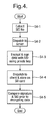
- Figure 4 is a flow diagram of the processing involved in downloading map data 65 from a remote server 60, when a user wishes to request a specific item of map data 65 from the server 60.
- the computer 40 sends a request via the USB interface lead 45 to the main control module 10 of the mapping system 1 asking the main control module 10 to extract (s4-1) a secure ID number from a secure digital card 20 on to which a map data is to be stored.
- This is achieved by the main control module 10 reading the secure ID from a secure digital card 20 inserted into the secure digital card interface 18 of the mapping system 1.
- This secure ID number is then passed (S4-2) via the computer 40 and the internet 55 to a remote server 60 together with the identification of the specific item of map data 65 desired by the user.
- the server 60 When a secure ID number and map data request are received by the server 60, the server proceeds to encrypt and sign (s4-3) the selected map data 65 using the received secure ID number for the secure digital card inserted in the navigational system 1 and the private key data 70.
- the encrypted and signed data is then (S4-4) transmitted back via the internet 55 and the computer 40 to the mapping system 1 where the encrypted data is stored with the memory of the secure digital card 20.
- the validity of the encrypted data can be checked by using the public key counterpart of the private key 70 to decrypt the signed data stored on the secure digital card 20. This will regenerate a copy of the secure ID number used originally with the private key 70. If this regenerated ID number corresponds to the ID number of the secure ID card 20 where the data is stored, this will indicate to the mapping system 1 that the encrypted map data stored directly onto the secure digital card 20 in response to a request received by the server 60.
- the above system is therefore suitable for distributing map data 65 in a controlled manner which subsequently prevents unauthorised copying of that map data 65 for other purposes.
- map data 65 in this embodiment reference has been made to secure digital cards, it will be appreciated than any other non-volatile storage medium with a built in unique identification data could be utilised.
- mapping system 1 in accordance with the present embodiment will now be described in detail with reference to Figures 5 - 7 .
- the main control module 10 initially (S5-1) causes the GPS module 12 to power up and initiate a connection to GPS satellite system. At the same time a back light for the display screen 3 is switched on so as to cause the display screen 3 to be active.
- the GPS module 12 Having been powered up the GPS module 12 then awaits signals from the visible GPS satellites. Received GPS signals are then processed by the GPS module 12 and a current position for the mapping system 1 is determined (S5-2). This position is then transferred by the GPS module 12 via the main control module 10 to the memory 19 where it is stored as position data 36.
- the main control module 10 Having determined the current location of the mapping system 1, the main control module 10 then proceeds (S5-3) to select and generate display data to be displayed to a user.
- the main control module 10 when determining data to be displayed on the display screen 3, the main control module 10 initially (S6-1) determines whether a raster map is available for display.
- map data 65 transferred and recorded on to a secure digital card 20 including boundary data identify the extent of the area for which high resolution map data is available.
- the main control module 10 compares the location of the mapping system 1 as identified by this data with the boundary data for the map information stored on the secure digital card 20 currently inserted in the SD interface 18 of the mapping system 1.
- the main control module 10 proceeds (s6-2) to access a pre-stored outline map data 34 stored within the memory 19.
- This pre-stored outline map data 34 is a low resolution vector map where outline route data is stored as vector data where roads and features are defined by a series of inter connected lines on a map which will enable the user to identify their general position based on the GPS signal.
- the resolution of the outline map data 34 could vary depending upon location. Thus, for example in the case of a mapping system 1 for use in the United Kingdom, outline map data 34 identifying the main roads in the UK could be provided, whereas outlines only of the other countries of world might be provided.
- mapping system 1 is always able to provide some display data for display the display screen 3. At the same time the mapping system 1 is relieved from having to store large amounts of high definition data for areas unlikely to be of interest.
- the main control module 10 determines (S6-1) that the current position of the mapping system 1 as identified by the latest item of stored position data 36 is within the boundaries for which high resolution map data 65 is stored within the secure digital card 20, the main control module 10 then confirms that the signature on the secure digital card 20 corresponds with the signature of the encrypted map data stored on the card.
- the main control module 10 then (S6-3) proceeds to decrypt and decompress a portion of the map data centred on the current position of the navigation device and stores the decrypted data within the map cache portion 38 of the memory 19.
- the map data stored on a secure digital card comprises pixel image data which is compressed using conventional techniques.
- the main control module 10 causes decompressed image data for the current display screen together with display data representing portions of map immediately adjacent the currently displayed map to be stored in the map cache 38
- the main control module 10 determines whether or not the joystick 8 is being activated. If this is the case the main control module 10 proceeds (S6-5) scroll the map data in the opposite direction indicated to that indicated by the activation of the joystick 8. Thus for example when the joystick 8 is pushed to the right, the map scrolls to the left. At the same time the main control module 10 proceeds to decrypt further map data from the map data 65 stored in secure digital card 20 where this additional data corresponds to additional map data in the direction indicated by the joystick 8. The additional decrypted data is then stored in the map cache portion 38 of the memory 19.
- the main control module 10 may generate display data at a lower resolution than the resolution of the decrypted map data within the map cache 38 when scrolling an image as due to the scrolling the reduction of resolution will be less apparent to a user.
- anti aliasing techniques which improve the apparent resolution of image data could be applied only when movement of the joystick has come to an end. Thus, avoiding such processing when due to the motion of an image, the increased resolution would not be apparent to the user.
- the main control module 10 determines the current mode for the mapping system 1.
- mapping system 1 is such to have two display modes, the mode in use being toggled by pressing mode button 6.
- the mode in use being toggled by pressing mode button 6.
- map data is displayed in a conventional manner with North appearing at the top of the screen display screen 3 and an indicator appearing on the screen indicating the current orientation of the mapping system 1 as determined by the compass module 14.
- map data is manipulated so as to appear rotated with an orientation corresponding to the orientation of the mapping system 1.
- main control module 10 determines that the current mode of operation is to display map data orientated so that the top of the image appearing on the screen corresponds to North
- main control module 10 causes to be sent to the display screen 3 display data corresponding to a section of map data stored within the map cache 38 centred upon a current position (i.e. either the position indicated by the latest stored item of position data 36 or an alternative position selected by virtue of moving the joystick 8).
- This map data is then displayed on the display screen 3 together with an indicator for indicating latest position 36 determined by the GPS module 12 as stored in memory 19.
- this indicator comprises a pointer indicating the current orientation of the mapping system 1 as determined by the compass module 14.
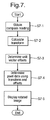
- the main control module 10 determines (S6-6) that the mode selected using the mode button 6 is such to cause the mapping system 1 to display data which is orientated in the direction corresponding to the orientation of the mapping system 1 itself, the main control module 10 then utilises the map data stored in the map cache 38 and the rotate tables 32 to generate an appropriate screen display (s6-8) showing a rotated map as will now be described with reference to Figure 7 .
- the main control module 10 when generating a display of map data orientated in an orientation corresponding to the orientation of the mapping system 1, initially (S7-1) the main control module 10 obtains a compass reading from the compass module 14 to determine the current orientation of the mapping system 1.
- a transform is calculated in the following form: cos ⁇ sin ⁇ - sin ⁇ cos ⁇ ⁇ Z 0 Z O
- ⁇ is the angle representing the difference of the compass reading obtained from the compass module 14 compared with a reading indicating due north
- Z is a zoom factor for mapping pixels in the rasta image data stored within the map cache 38 to pixels on the screen.
- control module 10 determines a set of two vector offsets applying the calculated transformation to a unit vector pointing in the x direction and unit vector pointing in the y direction respectively.
- Pixel data for generating an image for display on the screen is then (S7-4) generated using the calculated transform and the determined vector offsets. More specifically the calculated transform is first of all applied to a vector indicating the difference between the centre point on an image and the pixel representing the top left hand corner of the image. This value is then used to identify a set of four pixels for representing pixel data on the top left hand corner of the image screen by adding the calculated difference to a pointer identifying the centre of the map stored within the map cache 38. A set of pixel data for the pixel representing the top left hand corner of the display is then determined utilising the pixel data in the map cache 38. In this embodiment this is done in one of two ways.
- the position identified within the map cache 38 closest to the calculated point of value is determined.
- the calculated pointer corresponds to a position having x co-ordinates 37.4 and 38.9 the pixel at position 37 40 would be utilised to generate image data to represent the pixel in a top left hand corner of the screen.
- a waited average value for pixel data from the map cache is utilised.
- a value corresponding to the following waited sum would be used as pixel data for the pixel represented in the top left hand corner of the display: 0.6 ⁇ 0.1 37 ⁇ 38 + 0.6 ⁇ 0.9 37 ⁇ 38 + 0.4 ⁇ 0.1 38 ⁇ 38 + 0.4 ⁇ 0.9 38 ⁇ 39
- a bilateral filter is utilised to calculate the pixel values where the contributions of individual pixels and the map data in the map cache 38 are proportionate to the distance of the centre of the contributing pixels relative to the position as indicated by the pointer.
- the calculated unit vector offsets are then utilised to identify the portions of the map cache data 38 to be utilised to generate the remaining image data. This is achieved by adding the calculated vector offsets to the pointer value for the top left hand corner a number of times corresponding to the relative location of the pixel in the image and then generating pixel data based upon the revised pointer value.
- a single unit vector offset representing the unit vector offset for one pixel in the x direction would be added to the calculated point of value for the top left hand corner pixel.
- This operation is repeated until pixel data for each individual pixel in the image to be displayed has been calculated at which point a rasta image of rotated display data can then be caused to be displayed on the display screen 3.
- label data for all potential points of interest for example, roads, hills, town names etc.
- Each item of label data comprises an item of text data being the text to be displayed as a label on the map, size data indicating the size of the label when it is displayed and a series of map co-ordinates identifying possible positions which might be associated with the label.
- these position co-ordinates will correspond to various points along the road.
- the co-ordinates would correspond to points identifying the area covered by the geographical location.
- the main control module 10 When generating the final image for display on the display screen 3, the main control module 10 then proceeds to scan the positions corresponding to the locations displayed on the display screen starting from the top left hand corner of the display. Whenever a point associated with the co-ordinates of an item of location data is encountered, the label 4 corresponding to that point is caused to be displayed.
- the main control module 10 then continues to scan the area represented by the map, omitting the area now covered by a displayed label 4 and any label data associated with a label which has already been added to the display. In this way, the main control module 10 proceeds to generate display including labels for features of interest which are all correctly orientated for easy reading and which do not overlap.
- the main control module 10 determines whether a delay time has been exceeded. If this is not the case the mapping system 1 proceeds to determine and log its current position (S5-2) and display updated map data (S5-3) before checking again whether the on/off button 7 has been depressed.
- mapping system 1 is caused to display a map and update the map appropriately whilst a user may be viewing the map.
- the power consumption of the mapping system 1 is carefully controlled. To that end, providing an off button and also automatically powering down the system after a delay, the drain on energy resources is minimised. Further as will be explained the powering down of the mapping system 1 is also arranged to further reduce energy demands.
- the main control module 10 After either a user depresses (S5-3) the on/off button 7 or alternatively after a pre-determined time delay (S5-5) has passed, the main control module 10 then proceeds (S5-6) to power down the display screen 3 and the main processor for the navigation device 1. In this way the power consumption of the navigation device is reduced. In this way by powering up and powering down the screen and processor response to the on/off button, a user is given the impression that the unit is switched off by depressing this button as when the button is depressed the screen switches off.
- the main control module 10 will maintain some minimal functions.
- the main control module 10 will continue to monitor the control buttons to see whether the on/off 7 is pressed, and the GPS module 12 is maintained in an active state so as to continue to receive GPS signals.
- the main control module 10 detects that the on/off button 7 has been depressed, the main control module 10 responds by causing the display screen 3 and the main processor to be reactivated (S5-8). The main control module 10 then (S5-3) proceeds to generate appropriate map data as previously been described.
- the GPS module 12 which remains active, periodically determines and logs the current position of the mapping system 1.
- the GPS module 12 determines at each time a position is calculated, whether (S5-10) any change in position has occurred compared with the previous item of position data 36 stored in the memory. If the position of the mapping system 1 has changed beyond the margin of error inherent in calculating a position from GPS signals then a new item of the position data is stored in the memory 19 and a delay time is reset (S5-11). Thus in this way even when the mapping system 1 is ostensibly powered down, the mapping system 1 can continue to track the progress of a walker using the mapping system 1 and store a series of items of position data in the memory 19.
- the accuracy of GPS positioning is dependent both upon the number of satellites visible to a GPS unit (with positioning accuracy increasing with the number of visible satellites) and the relative positions of those satellites and the positioning unit. As such an apparent GPS position may appear to wander by a number of tens of meters even when no movement is occurring.
- a comparison between a current and previous position is made and the distance between the two is compared with a threshold (say for example 50m) and a new item of position data stored and the delay is reset only if the determined difference is greater than this "error" threshold.
- the GPS module 12 determines whether a delay period has been exceeded. If this is not the case the main control module 10 continues (S5-7) to monitor whether the on/off 7 is depressed and the GPS module 12 continues (S5-9) (S5-11) to periodically check and record the position of the mapping system 1 and reset a delay counter when movement is determined to have occurred.
- mapping system 1 can both to continue to log changes in position of a user of a mapping system 1 and also minimise its power consumption since the communication links between the GPS module 12 and the navigation satellite are maintained during that period.
- a series of way points identifying a route to be walked could be stored as part of data associated with map. These way points can then be indicated as points of interest on the map to a user to guide them along a selected route.
- position data 36 is described as being stored in the memory 19 of the mapping system 1.
- markers indicating the route taken by a user could be displayed as part of the map display.
- the position data 36 could also be used to identify changes in altitude taken by the user.
- One way in which this could be done would be to calculate the altitude of the mapping system 1 from the GPS signals received by the GPS module 12. Such altitude measurements are, however, unreliable.
- a preferred alternative would be to store as part of the map data 65, in addition to data for display, data associating points on a map with heights. In use, the GPS signals could then identify that the mapping system 1 was located at a particular position. The stored height data could be used as a look-up table to establish the altitude on the ground at that point.
- the height could be interpolated from height data associated with nearby. After having logged the variation in height of the mapping system 1, this data could be displayed to a user or alternatively the route and altitude data could be downloaded on to a computer 40 for subsequent display.
- non-volatile storage could either be formatted to provide a unique identifier or key or alternatively such a unique identifier or key could be generated by the mapping system itself and recorded on a non-volatile recording device. The identifier or key could then be combined with map data and a private key at a remote server in the manner previously described to link map with a specific non-volatile recording device.
Landscapes
- Engineering & Computer Science (AREA)
- Remote Sensing (AREA)
- Radar, Positioning & Navigation (AREA)
- Physics & Mathematics (AREA)
- General Physics & Mathematics (AREA)
- Automation & Control Theory (AREA)
- Computer Security & Cryptography (AREA)
- Theoretical Computer Science (AREA)
- Signal Processing (AREA)
- Computer Networks & Wireless Communication (AREA)
- General Engineering & Computer Science (AREA)
- Human Computer Interaction (AREA)
- Ecology (AREA)
- Educational Administration (AREA)
- Educational Technology (AREA)
- Business, Economics & Management (AREA)
- Mathematical Physics (AREA)
- Computing Systems (AREA)
- Life Sciences & Earth Sciences (AREA)
- Computer Hardware Design (AREA)
- Navigation (AREA)
- Instructional Devices (AREA)
- Traffic Control Systems (AREA)
Applications Claiming Priority (1)
| Application Number | Priority Date | Filing Date | Title |
|---|---|---|---|
| GB0702097A GB2446167B (en) | 2007-02-02 | 2007-02-02 | Mapping system |
Publications (1)
| Publication Number | Publication Date |
|---|---|
| EP1953501A2 true EP1953501A2 (de) | 2008-08-06 |
Family
ID=37891254
Family Applications (1)
| Application Number | Title | Priority Date | Filing Date |
|---|---|---|---|
| EP08250354A Withdrawn EP1953501A2 (de) | 2007-02-02 | 2008-01-30 | Landkarten- und Positionsanzeigesystem |
Country Status (6)
| Country | Link |
|---|---|
| US (1) | US20080189032A1 (de) |
| EP (1) | EP1953501A2 (de) |
| JP (1) | JP2008197093A (de) |
| AU (1) | AU2008200483A1 (de) |
| CA (1) | CA2619354A1 (de) |
| GB (1) | GB2446167B (de) |
Cited By (2)
| Publication number | Priority date | Publication date | Assignee | Title |
|---|---|---|---|---|
| WO2010112625A1 (es) * | 2009-03-31 | 2010-10-07 | Fundacion Fatronik | Método y dispositivo de orientación |
| US9354838B2 (en) | 2012-03-15 | 2016-05-31 | Volkswagen Aktiengesesllschaft | Method, mobile device and infotainment system for projecting a user interface onto a screen |
Families Citing this family (16)
| Publication number | Priority date | Publication date | Assignee | Title |
|---|---|---|---|---|
| US8731582B2 (en) * | 2008-02-08 | 2014-05-20 | Trimble Navigation Limited | Method and system for generating targeted content |
| WO2010005424A1 (en) | 2008-07-07 | 2010-01-14 | Primordial, Inc. | System and method for generating tactical routes |
| US8060582B2 (en) | 2008-10-22 | 2011-11-15 | Google Inc. | Geocoding personal information |
| JP4885336B2 (ja) * | 2010-02-12 | 2012-02-29 | 三菱電機株式会社 | 地図表示装置 |
| JP5912235B2 (ja) | 2010-07-27 | 2016-04-27 | 京セラ株式会社 | 触感呈示装置及び触感呈示装置の制御方法 |
| JP5841714B2 (ja) * | 2010-07-27 | 2016-01-13 | 京セラ株式会社 | 触感呈示装置及び触感呈示装置の制御方法 |
| JP5841713B2 (ja) | 2010-07-27 | 2016-01-13 | 京セラ株式会社 | 触感呈示装置及び触感呈示装置の制御方法 |
| US8374792B2 (en) * | 2010-07-30 | 2013-02-12 | Primordial Inc. | System and method for multi-resolution routing |
| US8805360B2 (en) | 2012-02-14 | 2014-08-12 | Apple Inc. | Wi-Fi process |
| US20130311898A1 (en) * | 2012-05-21 | 2013-11-21 | Nokia Corporation | Method and apparatus for navigation using multiple synchronized mobile devices |
| US10292105B2 (en) * | 2012-10-16 | 2019-05-14 | Apple Inc. | Motion-based adaptive scanning |
| US9912474B2 (en) * | 2013-09-27 | 2018-03-06 | Intel Corporation | Performing telemetry, data gathering, and failure isolation using non-volatile memory |
| CN106546256A (zh) * | 2015-09-23 | 2017-03-29 | 中兴通讯股份有限公司 | 电子导航的屏幕控制方法及装置 |
| JP6012061B1 (ja) * | 2016-03-22 | 2016-10-25 | 庸佑 壬生 | ナビゲーションシステム及びナビゲーションプログラム |
| US20180165838A1 (en) * | 2016-07-29 | 2018-06-14 | Faraday&Future Inc. | System and method for generating a semantically meaningful two-dimensional image from three-dimensional data |
| US10274331B2 (en) | 2016-09-16 | 2019-04-30 | Polaris Industries Inc. | Device and method for improving route planning computing devices |
Family Cites Families (26)
| Publication number | Priority date | Publication date | Assignee | Title |
|---|---|---|---|---|
| DE69313167T2 (de) * | 1992-02-18 | 1998-01-15 | Pioneer Electronic Corp | Navigationsvorrichtung mit verbesserter Positionsanzeigefunktion |
| US5528248A (en) * | 1994-08-19 | 1996-06-18 | Trimble Navigation, Ltd. | Personal digital location assistant including a memory cartridge, a GPS smart antenna and a personal computing device |
| DE69534757T2 (de) * | 1994-09-15 | 2006-08-31 | International Business Machines Corp. | System und Verfahren zur sicheren Speicherung und Verteilung von Daten unter Verwendung digitaler Unterschriften |
| JPH08292035A (ja) * | 1995-04-20 | 1996-11-05 | Matsushita Electric Ind Co Ltd | 電子マップ装置 |
| KR100278972B1 (ko) * | 1996-08-21 | 2001-01-15 | 모리 하루오 | 네비게이션장치 |
| US5902347A (en) * | 1996-11-19 | 1999-05-11 | American Navigation Systems, Inc. | Hand-held GPS-mapping device |
| JP2752607B2 (ja) * | 1996-12-24 | 1998-05-18 | 株式会社日立製作所 | ナビゲーション装置とその表示方法、及び地図表示装置とその表示方法 |
| JPH1138872A (ja) * | 1997-07-17 | 1999-02-12 | Toyota Motor Corp | 地図データ配信システム、およびそのシステムに適する地図データ取得装置 |
| US6163749A (en) * | 1998-06-05 | 2000-12-19 | Navigation Technologies Corp. | Method and system for scrolling a map display in a navigation application |
| JP2000098884A (ja) * | 1998-09-25 | 2000-04-07 | Jatco Corp | 地図表示装置 |
| US6122593A (en) * | 1999-08-03 | 2000-09-19 | Navigation Technologies Corporation | Method and system for providing a preview of a route calculated with a navigation system |
| US6529827B1 (en) * | 1999-11-01 | 2003-03-04 | Garmin Corporation | GPS device with compass and altimeter and method for displaying navigation information |
| US6768942B1 (en) * | 2000-09-18 | 2004-07-27 | Navigation Technologies Corp. | Navigation system with decryption functions and secure geographic database |
| US6366856B1 (en) * | 2000-11-21 | 2002-04-02 | Qualcomm Incorporated | Method and apparatus for orienting a map display in a mobile or portable device |
| KR100424462B1 (ko) * | 2001-11-21 | 2004-03-26 | 삼성전자주식회사 | 휴대용 단말기의 방향 및 위치 정보 표시장치 및 그 제어방법 |
| JP2003255040A (ja) * | 2002-02-28 | 2003-09-10 | Sony Corp | Gps受信機および受信方法 |
| JP2004101366A (ja) * | 2002-09-10 | 2004-04-02 | Hitachi Ltd | 携帯通信端末及びこれを用いたナビゲーションシステム |
| DE10255435A1 (de) * | 2002-11-28 | 2004-06-17 | Robert Bosch Gmbh | Fahrerinformationssystem |
| US20040167714A1 (en) * | 2003-02-24 | 2004-08-26 | Phil Macphail | Personal navigation device with orientation indicator |
| EP1655576B1 (de) * | 2004-10-27 | 2015-04-29 | Harman Becker Automotive Systems GmbH | Navigationssystem |
| US20060161349A1 (en) * | 2005-01-18 | 2006-07-20 | John Cross | GPS device and method for displaying raster images |
| JP2006208304A (ja) * | 2005-01-31 | 2006-08-10 | Clarion Co Ltd | ナビゲーション装置及びその方法並びにプログラム |
| JP2007010417A (ja) * | 2005-06-29 | 2007-01-18 | Shimizu Rie | ナビゲーション装置 |
| US7577516B2 (en) * | 2006-05-09 | 2009-08-18 | Hand Held Products, Inc. | Power management apparatus and methods for portable data terminals |
| US20080167801A1 (en) * | 2007-01-10 | 2008-07-10 | Pieter Geelen | Navigation device and method for establishing and using profiles |
| US8498804B2 (en) * | 2007-01-10 | 2013-07-30 | Tomtom International B.V. | Navigation device and method for conserving power |
-
2007
- 2007-02-02 GB GB0702097A patent/GB2446167B/en not_active Expired - Fee Related
-
2008
- 2008-01-30 EP EP08250354A patent/EP1953501A2/de not_active Withdrawn
- 2008-01-31 CA CA002619354A patent/CA2619354A1/en not_active Abandoned
- 2008-02-01 US US12/024,709 patent/US20080189032A1/en not_active Abandoned
- 2008-02-01 JP JP2008022551A patent/JP2008197093A/ja active Pending
- 2008-02-02 AU AU2008200483A patent/AU2008200483A1/en not_active Abandoned
Cited By (2)
| Publication number | Priority date | Publication date | Assignee | Title |
|---|---|---|---|---|
| WO2010112625A1 (es) * | 2009-03-31 | 2010-10-07 | Fundacion Fatronik | Método y dispositivo de orientación |
| US9354838B2 (en) | 2012-03-15 | 2016-05-31 | Volkswagen Aktiengesesllschaft | Method, mobile device and infotainment system for projecting a user interface onto a screen |
Also Published As
| Publication number | Publication date |
|---|---|
| GB2446167B (en) | 2011-08-17 |
| GB0702097D0 (en) | 2007-03-14 |
| US20080189032A1 (en) | 2008-08-07 |
| GB2446167A (en) | 2008-08-06 |
| CA2619354A1 (en) | 2008-08-02 |
| JP2008197093A (ja) | 2008-08-28 |
| AU2008200483A1 (en) | 2008-08-21 |
Similar Documents
| Publication | Publication Date | Title |
|---|---|---|
| EP1953501A2 (de) | Landkarten- und Positionsanzeigesystem | |
| US5991690A (en) | Navigation system incorporating simplified location display | |
| CN101029832B (zh) | 电子地图装置和电子地图显示方法 | |
| US7734413B2 (en) | Electronic device and program for displaying map | |
| JP3171145B2 (ja) | タッチパネルを併設した情報表示装置及び記憶媒体 | |
| US5552989A (en) | Portable digital map reader | |
| US20070103461A1 (en) | Virtual space image display method, apparatus, virtual space image display program, and recording medium | |
| ES2425555T3 (es) | Sistema de navegación que utiliza mapas de corredores | |
| US6445999B1 (en) | Navigation system and method of displaying a quasi-three-dimensional map information | |
| US7492966B2 (en) | Image mapping method and image mapping program | |
| JPH11311523A (ja) | 車両用ナビゲーション装置 | |
| EP1150101B1 (de) | Navigationssystem | |
| US20030148772A1 (en) | System and method for generating a directional indicator on a wireless communications device display | |
| JP3748042B2 (ja) | ナビゲーション装置 | |
| JP2004177148A (ja) | ナビゲーション装置、方法及びプログラム | |
| CN108885844A (zh) | 显示装置 | |
| US8712689B2 (en) | Method for computer-based determination of a position in a map, navigation device and mobile radio telephone | |
| JPH10161534A (ja) | 車載ナビゲーションシステムにおける情報入手装置 | |
| US8024113B2 (en) | Navigation system | |
| EP1003015A2 (de) | Verfahren zur Karteninformationsverarbeitung | |
| US20060109144A1 (en) | A method and device for customizing a local map with a grid that can be rotated and zoomed | |
| US20060149470A1 (en) | Consultation and processing system of information for hiking with the use of standard PDA hardware | |
| KR100695478B1 (ko) | 네비게이션 단말기용 테마 지도 구현 장치 및 방법 | |
| JP2003016469A (ja) | 画像表示方法、画像表示装置、差分情報管理方法、差分情報管理装置、画像表示システム、及び画像表示プログラム、並びに差分情報管理プログラム | |
| JP3775459B2 (ja) | 地図表示装置及び記憶媒体 |
Legal Events
| Date | Code | Title | Description |
|---|---|---|---|
| PUAI | Public reference made under article 153(3) epc to a published international application that has entered the european phase |
Free format text: ORIGINAL CODE: 0009012 |
|
| AK | Designated contracting states |
Kind code of ref document: A2 Designated state(s): AT BE BG CH CY CZ DE DK EE ES FI FR GB GR HR HU IE IS IT LI LT LU LV MC MT NL NO PL PT RO SE SI SK TR |
|
| AX | Request for extension of the european patent |
Extension state: AL BA MK RS |
|
| STAA | Information on the status of an ep patent application or granted ep patent |
Free format text: STATUS: THE APPLICATION HAS BEEN WITHDRAWN |
|
| 18W | Application withdrawn |
Effective date: 20120314 |