EP1953298A2 - Modular aufgebaute Handbrause - Google Patents
Modular aufgebaute Handbrause Download PDFInfo
- Publication number
- EP1953298A2 EP1953298A2 EP08001278A EP08001278A EP1953298A2 EP 1953298 A2 EP1953298 A2 EP 1953298A2 EP 08001278 A EP08001278 A EP 08001278A EP 08001278 A EP08001278 A EP 08001278A EP 1953298 A2 EP1953298 A2 EP 1953298A2
- Authority
- EP
- European Patent Office
- Prior art keywords
- hand shower
- water guide
- adapter
- handle
- head
- Prior art date
- Legal status (The legal status is an assumption and is not a legal conclusion. Google has not performed a legal analysis and makes no representation as to the accuracy of the status listed.)
- Granted
Links
Images


Classifications
-
- E—FIXED CONSTRUCTIONS
- E03—WATER SUPPLY; SEWERAGE
- E03C—DOMESTIC PLUMBING INSTALLATIONS FOR FRESH WATER OR WASTE WATER; SINKS
- E03C1/00—Domestic plumbing installations for fresh water or waste water; Sinks
- E03C1/02—Plumbing installations for fresh water
- E03C1/04—Water-basin installations specially adapted to wash-basins or baths
- E03C1/0408—Water installations especially for showers
- E03C1/0409—Shower handles
-
- B—PERFORMING OPERATIONS; TRANSPORTING
- B05—SPRAYING OR ATOMISING IN GENERAL; APPLYING FLUENT MATERIALS TO SURFACES, IN GENERAL
- B05B—SPRAYING APPARATUS; ATOMISING APPARATUS; NOZZLES
- B05B15/00—Details of spraying plant or spraying apparatus not otherwise provided for; Accessories
- B05B15/60—Arrangements for mounting, supporting or holding spraying apparatus
- B05B15/65—Mounting arrangements for fluid connection of the spraying apparatus or its outlets to flow conduits
-
- B—PERFORMING OPERATIONS; TRANSPORTING
- B05—SPRAYING OR ATOMISING IN GENERAL; APPLYING FLUENT MATERIALS TO SURFACES, IN GENERAL
- B05B—SPRAYING APPARATUS; ATOMISING APPARATUS; NOZZLES
- B05B1/00—Nozzles, spray heads or other outlets, with or without auxiliary devices such as valves, heating means
- B05B1/14—Nozzles, spray heads or other outlets, with or without auxiliary devices such as valves, heating means with multiple outlet openings; with strainers in or outside the outlet opening
- B05B1/18—Roses; Shower heads
Definitions
- the invention relates to a hand shower according to the preamble of claim 1.
- hand showers consist of many individual parts that have to be adapted to the changed geometries if the design or dimensions of the shower change. This concerns both the water supply in the handles and in the shower head and the Effervescent Rader Weg adopteden Roaden. In the provision of different design and size variants thus also creates an increased production and Vorvoreaufwand for the corresponding items.
- the invention is based on the object to design a hand shower so that their manufacturing costs in terms of possible shape or size variations is reduced.
- a hand shower which has a shower head with at least one Effervescent device and a handle in which a detachable connection for a hose for supplying water and at least one separate water supply is provided, wherein the water guide comprises at least two releasably but sealingly interconnected water supply elements ,
- the advantage of this Training is that the water guide elements do not have to correspond to the shape or curvature of the respective associated handle, but that the same water guide elements can be used for differently shaped hand showers or handles. These are connected to each other and thus adapted to the particular shape and size of the hand shower.
- the water supply is divided into at least one handle water guide pipe and a head water flow.
- the water guide elements are each connected to each other by means of an adapter.
- the entire water supply can be composed of a kind of modular system.
- the dimensions of the water guide elements are the same for different geometric configurations of the hand shower.
- the number of individual components can be further reduced, since the water supply is reduced to a standardized handle water guide tube and a head water flow.
- the adaptation of the water guide elements to different geometric configurations of the hand shower via the adapter which can be provided in different shapes, lengths and different angular positions.
- a development of the invention provides that the adapter is positively connected to the water guide elements, preferably locked. Alternatively, screw or plug connections are possible.
- the hand shower spacers are provided to the outer shell of the hand shower on the adapter and / or on at least one of the water guide elements. This creates an annular space around the water guide, so that the water supply is isolated from the surrounding housing or the handle shell and thus inflowing Water does not affect the temperature of the housing. Since the outer shell is usually made of plastic and provided with at least one metallic decorative layer, unwanted heat expansions in the housing can be substantially excluded by the air layer in the annulus, so that a spalling of the decorative layer is prevented due to changing temperature loads.
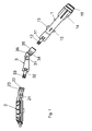
- FIG. 1 and Fig. 2 show an inventive water supply in an exploded view.
- the Griffigan arrangementsrohr 1 has two elastically resilient ribs 11, each with an eye opening 12, which cooperate with latching lugs 31 on the adapter 3 in the latched state.
- resilient ribs 32 are provided with eye openings 33 which receive latching lugs 21 of the head water guide 2 in the assembled state.
- both the head water guide 2 and the adapter 3 at the connection 22, 35 which engages in the opening of the adapter 3 and the handle water guide tube 1, depending on an annular groove 23, 34 for a sealing ring.
- a thread 15 is provided for connection to a shower hose.
- spacers 13, 14, 36 are integrally formed on the handle water guide tube 1 circumferentially at several points. This results in the installed state, an annular space between the water supply 1.3 and outer shell. 4
- Fig. 3 shows a hand shower according to the invention in the final state with inserted water guide and shower jet producing device 5.
- the rib-shaped spacers 13, 14, 36 decouple the water supply from the outer shell 4 of the hand shower.
- the contact points are reduced to a minimum.
- stress or strain cracks due to temperature changes in the applied on the outer shell 4 decorative layer, which often consists of a chromium layer can be avoided.
- Figure 4 shows a further embodiment of a hand shower according to the invention.
- This has a square design in the head area.
- the shower head 6 to a larger extent.
- identical components can be used for the handle water guide tube 1 and the head water guide 2.
- a variable adapter 3 is used in each case.
Landscapes
- Health & Medical Sciences (AREA)
- Life Sciences & Earth Sciences (AREA)
- Engineering & Computer Science (AREA)
- Hydrology & Water Resources (AREA)
- Public Health (AREA)
- Water Supply & Treatment (AREA)
- Bathtubs, Showers, And Their Attachments (AREA)
- Nozzles (AREA)
Abstract
Um den Fertigungsaufwand in Bezug auf mögliche Form- und Größenvariationen zu verringern sind die beiden Wasserführungselemente (1,2) mittels eines Adapters (3) miteinander verbunden. So können unterschiedliche Wasserführungselemente (1,2) vielfach kombiniert werden.
Description
- Die Erfindung betrifft eine Handbrause gemäß dem Oberbegriff des Anspruchs 1.
- Handbrausen bestehen in Abhängigkeit von ihrer Funktionalität aus vielen Einzelteilen, die bei Änderung des Designs oder der Abmessungen der Brause an die veränderten Geometrien angepasst werden müssen. Dies betrifft sowohl die Wasserzuführung in den Handgriffen und im Brausekopf als auch die Brausestrahlerzeugniseinrichtungen. Bei der Bereitstellung von unterschiedlichen Design- und Größenvarianten entsteht somit auch ein erhöhter Fertigungs- und Vorhalteaufwand für die entsprechenden Einzelteile.
- Der Erfindung liegt die Aufgabe zu Grunde, eine Handbrause so zu gestalten, dass deren Fertigungsaufwand in Bezug auf mögliche Form- oder Größenvariationen verringert wird.
- Diese Aufgabe wird erfindungsgemäß durch eine Handbrause gemäß dem kennzeichnenden Teil des Anspruchs 1 gelöst.
- Hierzu wird eine Handbrause bereitgestellt, die einen Brausekopf mit wenigstens einer Brausestrahlerzeugniseinrichtung und einen Handgriff aufweist, bei dem ein lösbarer Anschluss für eine Schlauchleitung zur Zuführung von Wasser und wenigstens eine separate Wasserführung vorgesehen ist, wobei die Wasserführung wenigstens zwei lösbar aber dichtend miteinander verbundene Wasserführungselemente umfasst. Der Vorteil dieser Ausbildung besteht darin, dass die Wasserführungselemente nicht der Form oder Krümmung des jeweiligen zugehörigen Handgriffs entsprechen müssen, sondern dass für unterschiedlich geformte Handbrausen oder Griffe dieselben Wasserführungselemente verwendet werden können. Diese werden miteinander verbunden und somit an die jeweilige Form und Größe der Handbrause angepasst.
- Dabei ist es vorteilhaft, wenn die Wasserführung in wenigstens ein Griffwasserführungsrohr und eine Kopfwasserführung unterteilt ist.
In einer Weiterbildung der Erfindung sind die Wasserführungselemente jeweils mittels eines Adapters miteinander verbunden. Somit kann die gesamte Wasserführung aus einer Art Baukastensystem zusammengesetzt werden. Mittels einer begrenzten Anzahl von standardisierten Einzelteilen für die Wasserführungen und Adapter kann eine Vielzahl von Handbrausen unterschiedlichen Designs und unterschiedlicher Größe ausgestattet werden. - Vorteilhaft ist weiterhin eine Handbrause vorzusehen, bei der die Abmessungen der Wasserführungselemente gleich bleibend bei unterschiedlichen geometrischen Ausgestaltungen der Handbrause sind. Somit kann die Anzahl der Einzelkomponenten weiter reduziert werden, da die Wasserführung auf ein standardisiertes Griffwasserführungsrohr und eine Kopfwasserführung reduziert ist. Die Anpassung der Wasserführungselemente an unterschiedliche geometrische Ausgestaltungen der Handbrause erfolgt über den Adapter, der dazu in unterschiedlichen Formen, Längen und mit unterschiedlichen Winkelstellungen bereitgestellt werden kann.
Eine Weiterbildung der Erfindung sieht vor, dass der Adapter mit den Wasserführungselementen formschlüssig verbunden, vorzugsweise verrastet ist. Alternativ dazu sind auch Schraub- oder Steckverbindungen möglich. - Gemäß einer vorteilhaften Ausbildung der Handbrause sind an dem Adapter und/oder an wenigstens einem der Wasserführungselemente Abstandshalter zur Außenschale der Handbrause vorgesehen. Dadurch entsteht um die Wasserführung ein Ringraum, so dass die Wasserführung von dem umgebenden Gehäuse bzw. der Griffschale isoliert ist und somit zufließendes Wasser keinen Einfluss auf die Temperatur des Gehäuses hat. Da die Außenschale üblicherweise aus Kunststoff hergestellt und mit wenigstens einer metallenen Dekorschicht versehen werden, können durch die Luftschicht im Ringraum unerwünschte Wärmedehnungen im Gehäuse im Wesentlichen ausgeschlossen werden, so dass ein Abplatzen der Dekorschicht aufgrund wechselnder Temperaturbelastungen verhindert wird.
- Ein Ausführungsbeispiel der Erfindung ist in den Zeichnungen dargestellt und wird im Folgenden näher beschrieben. Es zeigt in der Zeichnung
- Figur 1
- eine Seitenansicht einer Wasserführung in Explosionsdarstellung
- Figur 2
- eine Draufsicht auf eine Wasserführung in Explosionsdarstellung
- Figur 3
- einen Längsschnitt durch eine erfindungsgemäße Handbrause
- Figur 4
- einen Längsschnitt durch eine weitere Ausführungsform einer erfindungsgemäßen Handbrause
-
Figur 1 undFig. 2 zeigen eine erfindungsgemäße Wasserführung in Explosionsdarstellung. Die Wasserführung umfasst ein Griffwasserführungsrohr 1, einen Adapter 3 und eine Kopfwasserführung 2. Zur formschlüssigen Verbindung mit dem Adapter 3 weist das Griffwasserführungsrohr 1 zwei elastisch federnde Rippen 11 mit je einer Augenöffnung 12 auf, die im verrasteten Zustand mit Rastnasen 31 am Adapter 3 zusammenwirken. Auch am Adapter 3 sind wiederum federnde Rippen 32 mit Augenöffnungen 33 vorgesehen, die im zusammengesetzten Zustand Rastnasen 21 der Kopfwasserführung 2 aufnehmen. Zur wasserdichten Verbindung der Einzelkomponenten weisen sowohl die Kopfwasserführung 2 als auch der Adapter 3 an dem Anschluss 22, 35, der in die Öffnung des Adapters 3 bzw. des Griffwasserführungsrohrs 1 greift, je eine Ringnut 23, 34 für einen Dichtungsring auf. - Auf der dem Adapter 3 abgewandten Seite des Griffasserführungsrohres 1 ist zum Anschluss an einen Brauseschlauch ein Gewinde 15 vorgesehen.
Damit die Wasserführung nicht im direkten Kontakt mit der Außenschale 4 der Handbrause steht, sind an dem Griffwasserführungsrohr 1 umlaufend an mehreren Stellen Abstandshalter 13, 14, 36 angeformt. Dadurch entsteht im eingebauten Zustand ein Ringraum zwischen Wasserführung 1,3 und Außenschale 4. -
Fig. 3 zeigt eine erfindungsgemäße Handbrause im Endzustand mit eingesetzter Wasserführung und Brausestrahlerzeugniseinrichtung 5. Die rippenförmigen Abstandhalter 13, 14, 36 entkoppeln die Wasserführung von der Außenschale 4 der Handbrause. Die Kontaktstellen werden auf ein Minimum reduziert. Dadurch können Spannungs- oder Dehnungsrisse aufgrund von Temperaturänderungen in der auf der Außenschale 4 aufgebrachten Dekorschicht, die oftmals aus einer Chromschicht besteht, vermieden werden. -
Fig.4 zeigt eine weitere Ausgestaltung einer erfindungsgemäßen Handbrause. Im Gegensatz zur Handbrause inFig. 3 weist diese im Kopfbereich ein eckiges Design auf. Zudem weist der Brausekopf 6 einen größeren Umfang auf.
Trotz der unterschiedlichen Außenabmessungen der Brausen können für das Griffwasserführungsrohr 1 und die Kopfwasserführung 2 identische Bauteile verwendet werden. Zur Anpassung an die unterschiedlichen Geometrien wird jeweils ein variabler Adapter 3 eingesetzt. -
1 Griffwasserführungsrohr 11 Rippe 12 Augenöffnung 13 Abstandhalter 14 Abstandhalter 15 Gewinde 2 Kopfwasserführung 21 Rastnase 22 Anschluss 23 Ringnut 3 Adapter 31 Rastnase 32 Rippe 33 Augenöffnung 34 Ringnut 35 Anschluss 36 Abstandhalter 4 Außenschale 5 Brausestrahlerzeugniseinrichtung 6 Brausekopf 7 Handgriff
Claims (8)
- Handbrause mit- einem Brausekopf (6),- wenigstens einer Brausestrahlerzeugniseinrichtung (5) und- einem Handgriff (7),- - bei dem ein lösbarer Anschluss (15) für eine Schlauchleitung zur Zuführung von Wasser und wenigstens eine separate Wasserführung vorgesehen ist, die wenigstens zwei lösbar miteinander verbundene Wasserführungselemente (1, 2) umfasst,dadurch gekennzeichnet, dass- - - die Wasserführungselemente (1, 2) mittels eines Adapters (3) miteinander verbunden sind.
- Handbrause nach Anspruch 1, dadurch gekennzeichnet, dass die Abmessungen der Wasserführungselemente (1, 2) gleich bleibend bei unterschiedlichen geometrischen Ausgestaltungen der Handbrause vorgesehen sind.
- Handbrause nach Anspruch 1 oder 2, dadurch gekennzeichnet, dass als Wasserführungselemente wenigstens ein Griffwasserführungsrohr (1) und eine Kopfwasserführung (2) vorgesehen sind.
- Handbrause nach Anspruch 3, dadurch gekennzeichnet, dass der Adapter (3) zur Anpassung des Griffwasserführungsrohres (1) und der Kopfwasserführung (2) an unterschiedliche geometrische Ausgestaltungen der Handbrause vorgesehen ist.
- Handbrause nach einem der vorhergehenden Ansprüche, dadurch gekennzeichnet, dass Adapter (3) und Wasserführungselemente (1, 2) formschlüssig miteinander verbunden sind.
- Handbrause nach einem der vorhergehenden Ansprüche, dadurch gekennzeichnet, dass der Adapter (3) mit den Wasserführungselementen (1, 2) verrastet ist.
- Handbrause nach einem der vorgehenden Ansprüche, dadurch gekennzeichnet, dass an wenigstens einem der Wasserführungselemente (1, 2) Abstandshalter (13, 14) zur Außenschale (4) vorgesehen sind.
- Handbrause nach einem der vorhergehenden Ansprüche, dadurch gekennzeichnet, dass an dem Adapter (3) Abstandshalter (36) zur Außenschale (4) der Handbrause vorgesehen sind.
Applications Claiming Priority (1)
| Application Number | Priority Date | Filing Date | Title |
|---|---|---|---|
| DE102007005851A DE102007005851B4 (de) | 2007-02-01 | 2007-02-01 | Handbrause |
Publications (3)
| Publication Number | Publication Date |
|---|---|
| EP1953298A2 true EP1953298A2 (de) | 2008-08-06 |
| EP1953298A3 EP1953298A3 (de) | 2012-02-29 |
| EP1953298B1 EP1953298B1 (de) | 2016-06-08 |
Family
ID=39295035
Family Applications (1)
| Application Number | Title | Priority Date | Filing Date |
|---|---|---|---|
| EP08001278.4A Not-in-force EP1953298B1 (de) | 2007-02-01 | 2008-01-24 | Modular aufgebaute Handbrause |
Country Status (2)
| Country | Link |
|---|---|
| EP (1) | EP1953298B1 (de) |
| DE (1) | DE102007005851B4 (de) |
Families Citing this family (1)
| Publication number | Priority date | Publication date | Assignee | Title |
|---|---|---|---|---|
| DE102011101941B4 (de) | 2011-05-18 | 2024-07-18 | Grohe Ag | Sanitärarmatur oder Brause |
Family Cites Families (8)
| Publication number | Priority date | Publication date | Assignee | Title |
|---|---|---|---|---|
| US3637143A (en) * | 1969-05-28 | 1972-01-25 | Melard Mfg Corp | Handle-controlled spray |
| DE2028937B2 (de) * | 1970-06-12 | 1973-06-20 | Franz Scheffer Ohg, 5750 Menden | Badezimmerhandbrause |
| DE4116932A1 (de) * | 1991-05-24 | 1992-11-26 | Grohe Armaturen Friedrich | Handbrause |
| DE4308991A1 (de) * | 1993-03-20 | 1994-09-22 | Grohe Kg Hans | Handbrause |
| DE29619359U1 (de) * | 1996-11-07 | 1997-01-09 | Winkelmann, Harald, 04860 Torgau | Doppelkammer-Handdusche |
| US6789751B1 (en) * | 2003-03-25 | 2004-09-14 | Winner Double-H Co., Ltd. | Collapsible handle for a shower head |
| DE102004036313A1 (de) * | 2004-07-27 | 2006-02-16 | Grohe Water Technology Ag & Co. Kg | Handbrause |
| DE202004018265U1 (de) * | 2004-11-25 | 2005-02-03 | Ho, Hsin-Jon | Duschkopf |
-
2007
- 2007-02-01 DE DE102007005851A patent/DE102007005851B4/de not_active Expired - Fee Related
-
2008
- 2008-01-24 EP EP08001278.4A patent/EP1953298B1/de not_active Not-in-force
Also Published As
| Publication number | Publication date |
|---|---|
| EP1953298A3 (de) | 2012-02-29 |
| DE102007005851A1 (de) | 2008-08-14 |
| DE102007005851B4 (de) | 2010-12-16 |
| EP1953298B1 (de) | 2016-06-08 |
Similar Documents
| Publication | Publication Date | Title |
|---|---|---|
| EP0715112A2 (de) | Einrichtung zum Zusammenschalten mehrerer Elektromagnetventile | |
| DE2431680A1 (de) | Verteiler in elementbauweise fuer flude | |
| DE202014006320U1 (de) | Anschlussvorrichtung und sanitäre Anlage | |
| DE112015002523T5 (de) | Modulare Verteilerleitung für einen Wasserdurchlauferhitzer | |
| EP2366923A2 (de) | Ventilbaugruppe | |
| WO2018130422A1 (de) | Axial-steuerventil zur steuerung des volumenstroms in einer gasleitung | |
| CH653426A5 (de) | Verbindungsvorrichtung fuer sanitaerinstallationen mit flexibler, beiderends anschlussmittel aufweisender verbindungsleitung. | |
| EP2366922B1 (de) | Ventilknoten | |
| EP1953298B1 (de) | Modular aufgebaute Handbrause | |
| EP2334968B1 (de) | Verschlusskupplung | |
| DE2829216C2 (de) | Heizmittelverteiler | |
| EP2460943B1 (de) | Spülkasten | |
| EP2366924B1 (de) | Ventilknoten | |
| EP3000926A1 (de) | Wasserverteileinrichtung für eine spülmaschine oder eine waschmaschine | |
| DE10233863B4 (de) | Anschlussblock für Sanitärarmaturen | |
| DE102011003864B4 (de) | Einsatz für den Wasserauslass aus einer Sanitärarmatur | |
| EP3705637B1 (de) | Wandmontierbare sanitäre verteiler- und leitungsanschlussvorrichtung mit integrierten ventilen | |
| DE10114992C1 (de) | Heizkörper-Anschlußarmatur und Heizkörper | |
| EP1614944B1 (de) | Mehrwegemisch- oder verteilventil | |
| DE2923231C2 (de) | ||
| EP2840057A1 (de) | Reinigungseinrichtung für einen Zapfhahn | |
| DE102012005464B4 (de) | Vorrichtung zum Anschließen eines Urinals an das Wassernetz | |
| DE10143296A1 (de) | Kabeldurchführungssystem für konfektionierte Leitungen | |
| EP1435480A2 (de) | Sanitärarmatur | |
| DE10114926A1 (de) | Verteilerventil |
Legal Events
| Date | Code | Title | Description |
|---|---|---|---|
| PUAI | Public reference made under article 153(3) epc to a published international application that has entered the european phase |
Free format text: ORIGINAL CODE: 0009012 |
|
| AK | Designated contracting states |
Kind code of ref document: A2 Designated state(s): AT BE BG CH CY CZ DE DK EE ES FI FR GB GR HR HU IE IS IT LI LT LU LV MC MT NL NO PL PT RO SE SI SK TR |
|
| AX | Request for extension of the european patent |
Extension state: AL BA MK RS |
|
| PUAL | Search report despatched |
Free format text: ORIGINAL CODE: 0009013 |
|
| AK | Designated contracting states |
Kind code of ref document: A3 Designated state(s): AT BE BG CH CY CZ DE DK EE ES FI FR GB GR HR HU IE IS IT LI LT LU LV MC MT NL NO PL PT RO SE SI SK TR |
|
| AX | Request for extension of the european patent |
Extension state: AL BA MK RS |
|
| RIC1 | Information provided on ipc code assigned before grant |
Ipc: E03C 1/04 20060101AFI20120126BHEP |
|
| 17P | Request for examination filed |
Effective date: 20120829 |
|
| AKX | Designation fees paid |
Designated state(s): AT BE BG CH CY CZ DE DK EE ES FI FR GB GR HR HU IE IS IT LI LT LU LV MC MT NL NO PL PT RO SE SI SK TR |
|
| 17Q | First examination report despatched |
Effective date: 20140825 |
|
| 111Z | Information provided on other rights and legal means of execution |
Free format text: AT BE BG CH CY CZ DE DK EE ES FI FR GB GR HR HU IE IS IT LT LU LV MC MT NL NO PL PT RO SE SI SK TR Effective date: 20141212 |
|
| D11X | Information provided on other rights and legal means of execution (deleted) | ||
| GRAP | Despatch of communication of intention to grant a patent |
Free format text: ORIGINAL CODE: EPIDOSNIGR1 |
|
| INTG | Intention to grant announced |
Effective date: 20151222 |
|
| GRAS | Grant fee paid |
Free format text: ORIGINAL CODE: EPIDOSNIGR3 |
|
| GRAA | (expected) grant |
Free format text: ORIGINAL CODE: 0009210 |
|
| AK | Designated contracting states |
Kind code of ref document: B1 Designated state(s): AT BE BG CH CY CZ DE DK EE ES FI FR GB GR HR HU IE IS IT LI LT LU LV MC MT NL NO PL PT RO SE SI SK TR |
|
| REG | Reference to a national code |
Ref country code: GB Ref legal event code: FG4D Free format text: NOT ENGLISH |
|
| REG | Reference to a national code |
Ref country code: CH Ref legal event code: EP |
|
| REG | Reference to a national code |
Ref country code: IE Ref legal event code: FG4D Free format text: LANGUAGE OF EP DOCUMENT: GERMAN |
|
| REG | Reference to a national code |
Ref country code: AT Ref legal event code: REF Ref document number: 805359 Country of ref document: AT Kind code of ref document: T Effective date: 20160715 |
|
| REG | Reference to a national code |
Ref country code: DE Ref legal event code: R096 Ref document number: 502008014276 Country of ref document: DE |
|
| REG | Reference to a national code |
Ref country code: CH Ref legal event code: NV Representative=s name: COSMOVICI INTELLECTUAL PROPERTY SARL, CH |
|
| REG | Reference to a national code |
Ref country code: NL Ref legal event code: FP |
|
| REG | Reference to a national code |
Ref country code: LT Ref legal event code: MG4D |
|
| PG25 | Lapsed in a contracting state [announced via postgrant information from national office to epo] |
Ref country code: NO Free format text: LAPSE BECAUSE OF FAILURE TO SUBMIT A TRANSLATION OF THE DESCRIPTION OR TO PAY THE FEE WITHIN THE PRESCRIBED TIME-LIMIT Effective date: 20160908 Ref country code: LT Free format text: LAPSE BECAUSE OF FAILURE TO SUBMIT A TRANSLATION OF THE DESCRIPTION OR TO PAY THE FEE WITHIN THE PRESCRIBED TIME-LIMIT Effective date: 20160608 Ref country code: FI Free format text: LAPSE BECAUSE OF FAILURE TO SUBMIT A TRANSLATION OF THE DESCRIPTION OR TO PAY THE FEE WITHIN THE PRESCRIBED TIME-LIMIT Effective date: 20160608 |
|
| PG25 | Lapsed in a contracting state [announced via postgrant information from national office to epo] |
Ref country code: LV Free format text: LAPSE BECAUSE OF FAILURE TO SUBMIT A TRANSLATION OF THE DESCRIPTION OR TO PAY THE FEE WITHIN THE PRESCRIBED TIME-LIMIT Effective date: 20160608 Ref country code: ES Free format text: LAPSE BECAUSE OF FAILURE TO SUBMIT A TRANSLATION OF THE DESCRIPTION OR TO PAY THE FEE WITHIN THE PRESCRIBED TIME-LIMIT Effective date: 20160608 Ref country code: SE Free format text: LAPSE BECAUSE OF FAILURE TO SUBMIT A TRANSLATION OF THE DESCRIPTION OR TO PAY THE FEE WITHIN THE PRESCRIBED TIME-LIMIT Effective date: 20160608 Ref country code: HR Free format text: LAPSE BECAUSE OF FAILURE TO SUBMIT A TRANSLATION OF THE DESCRIPTION OR TO PAY THE FEE WITHIN THE PRESCRIBED TIME-LIMIT Effective date: 20160608 Ref country code: GR Free format text: LAPSE BECAUSE OF FAILURE TO SUBMIT A TRANSLATION OF THE DESCRIPTION OR TO PAY THE FEE WITHIN THE PRESCRIBED TIME-LIMIT Effective date: 20160909 |
|
| REG | Reference to a national code |
Ref country code: FR Ref legal event code: PLFP Year of fee payment: 10 |
|
| PG25 | Lapsed in a contracting state [announced via postgrant information from national office to epo] |
Ref country code: EE Free format text: LAPSE BECAUSE OF FAILURE TO SUBMIT A TRANSLATION OF THE DESCRIPTION OR TO PAY THE FEE WITHIN THE PRESCRIBED TIME-LIMIT Effective date: 20160608 Ref country code: SK Free format text: LAPSE BECAUSE OF FAILURE TO SUBMIT A TRANSLATION OF THE DESCRIPTION OR TO PAY THE FEE WITHIN THE PRESCRIBED TIME-LIMIT Effective date: 20160608 Ref country code: RO Free format text: LAPSE BECAUSE OF FAILURE TO SUBMIT A TRANSLATION OF THE DESCRIPTION OR TO PAY THE FEE WITHIN THE PRESCRIBED TIME-LIMIT Effective date: 20160608 Ref country code: IS Free format text: LAPSE BECAUSE OF FAILURE TO SUBMIT A TRANSLATION OF THE DESCRIPTION OR TO PAY THE FEE WITHIN THE PRESCRIBED TIME-LIMIT Effective date: 20161008 Ref country code: CZ Free format text: LAPSE BECAUSE OF FAILURE TO SUBMIT A TRANSLATION OF THE DESCRIPTION OR TO PAY THE FEE WITHIN THE PRESCRIBED TIME-LIMIT Effective date: 20160608 |
|
| PG25 | Lapsed in a contracting state [announced via postgrant information from national office to epo] |
Ref country code: PT Free format text: LAPSE BECAUSE OF FAILURE TO SUBMIT A TRANSLATION OF THE DESCRIPTION OR TO PAY THE FEE WITHIN THE PRESCRIBED TIME-LIMIT Effective date: 20161010 Ref country code: PL Free format text: LAPSE BECAUSE OF FAILURE TO SUBMIT A TRANSLATION OF THE DESCRIPTION OR TO PAY THE FEE WITHIN THE PRESCRIBED TIME-LIMIT Effective date: 20160608 |
|
| REG | Reference to a national code |
Ref country code: DE Ref legal event code: R097 Ref document number: 502008014276 Country of ref document: DE |
|
| PLBE | No opposition filed within time limit |
Free format text: ORIGINAL CODE: 0009261 |
|
| STAA | Information on the status of an ep patent application or granted ep patent |
Free format text: STATUS: NO OPPOSITION FILED WITHIN TIME LIMIT |
|
| 26N | No opposition filed |
Effective date: 20170309 |
|
| PG25 | Lapsed in a contracting state [announced via postgrant information from national office to epo] |
Ref country code: SI Free format text: LAPSE BECAUSE OF FAILURE TO SUBMIT A TRANSLATION OF THE DESCRIPTION OR TO PAY THE FEE WITHIN THE PRESCRIBED TIME-LIMIT Effective date: 20160608 Ref country code: DK Free format text: LAPSE BECAUSE OF FAILURE TO SUBMIT A TRANSLATION OF THE DESCRIPTION OR TO PAY THE FEE WITHIN THE PRESCRIBED TIME-LIMIT Effective date: 20160608 Ref country code: BE Free format text: LAPSE BECAUSE OF NON-PAYMENT OF DUE FEES Effective date: 20170131 |
|
| PG25 | Lapsed in a contracting state [announced via postgrant information from national office to epo] |
Ref country code: MC Free format text: LAPSE BECAUSE OF FAILURE TO SUBMIT A TRANSLATION OF THE DESCRIPTION OR TO PAY THE FEE WITHIN THE PRESCRIBED TIME-LIMIT Effective date: 20160608 |
|
| REG | Reference to a national code |
Ref country code: IE Ref legal event code: MM4A |
|
| PG25 | Lapsed in a contracting state [announced via postgrant information from national office to epo] |
Ref country code: LU Free format text: LAPSE BECAUSE OF NON-PAYMENT OF DUE FEES Effective date: 20170124 |
|
| REG | Reference to a national code |
Ref country code: CH Ref legal event code: PCAR Free format text: NEW ADDRESS: 14 RUE DU RHONE, 1204 GENEVE (CH) |
|
| REG | Reference to a national code |
Ref country code: FR Ref legal event code: PLFP Year of fee payment: 11 |
|
| REG | Reference to a national code |
Ref country code: BE Ref legal event code: MM Effective date: 20170131 |
|
| PG25 | Lapsed in a contracting state [announced via postgrant information from national office to epo] |
Ref country code: IE Free format text: LAPSE BECAUSE OF NON-PAYMENT OF DUE FEES Effective date: 20170124 |
|
| PG25 | Lapsed in a contracting state [announced via postgrant information from national office to epo] |
Ref country code: MT Free format text: LAPSE BECAUSE OF FAILURE TO SUBMIT A TRANSLATION OF THE DESCRIPTION OR TO PAY THE FEE WITHIN THE PRESCRIBED TIME-LIMIT Effective date: 20160608 |
|
| PG25 | Lapsed in a contracting state [announced via postgrant information from national office to epo] |
Ref country code: HU Free format text: LAPSE BECAUSE OF FAILURE TO SUBMIT A TRANSLATION OF THE DESCRIPTION OR TO PAY THE FEE WITHIN THE PRESCRIBED TIME-LIMIT; INVALID AB INITIO Effective date: 20080124 |
|
| PG25 | Lapsed in a contracting state [announced via postgrant information from national office to epo] |
Ref country code: BG Free format text: LAPSE BECAUSE OF FAILURE TO SUBMIT A TRANSLATION OF THE DESCRIPTION OR TO PAY THE FEE WITHIN THE PRESCRIBED TIME-LIMIT Effective date: 20160608 |
|
| PG25 | Lapsed in a contracting state [announced via postgrant information from national office to epo] |
Ref country code: CY Free format text: LAPSE BECAUSE OF NON-PAYMENT OF DUE FEES Effective date: 20160608 |
|
| PG25 | Lapsed in a contracting state [announced via postgrant information from national office to epo] |
Ref country code: TR Free format text: LAPSE BECAUSE OF FAILURE TO SUBMIT A TRANSLATION OF THE DESCRIPTION OR TO PAY THE FEE WITHIN THE PRESCRIBED TIME-LIMIT Effective date: 20160608 |
|
| PGFP | Annual fee paid to national office [announced via postgrant information from national office to epo] |
Ref country code: NL Payment date: 20200121 Year of fee payment: 13 Ref country code: IT Payment date: 20200131 Year of fee payment: 13 Ref country code: AT Payment date: 20200122 Year of fee payment: 13 |
|
| PGFP | Annual fee paid to national office [announced via postgrant information from national office to epo] |
Ref country code: CH Payment date: 20200121 Year of fee payment: 13 |
|
| REG | Reference to a national code |
Ref country code: CH Ref legal event code: PL |
|
| REG | Reference to a national code |
Ref country code: NL Ref legal event code: MM Effective date: 20210201 |
|
| REG | Reference to a national code |
Ref country code: AT Ref legal event code: MM01 Ref document number: 805359 Country of ref document: AT Kind code of ref document: T Effective date: 20210124 |
|
| PG25 | Lapsed in a contracting state [announced via postgrant information from national office to epo] |
Ref country code: AT Free format text: LAPSE BECAUSE OF NON-PAYMENT OF DUE FEES Effective date: 20210124 Ref country code: NL Free format text: LAPSE BECAUSE OF NON-PAYMENT OF DUE FEES Effective date: 20210201 |
|
| PG25 | Lapsed in a contracting state [announced via postgrant information from national office to epo] |
Ref country code: LI Free format text: LAPSE BECAUSE OF NON-PAYMENT OF DUE FEES Effective date: 20210131 Ref country code: CH Free format text: LAPSE BECAUSE OF NON-PAYMENT OF DUE FEES Effective date: 20210131 |
|
| PG25 | Lapsed in a contracting state [announced via postgrant information from national office to epo] |
Ref country code: IT Free format text: LAPSE BECAUSE OF NON-PAYMENT OF DUE FEES Effective date: 20210124 |
|
| PGFP | Annual fee paid to national office [announced via postgrant information from national office to epo] |
Ref country code: GB Payment date: 20220119 Year of fee payment: 15 |
|
| PGFP | Annual fee paid to national office [announced via postgrant information from national office to epo] |
Ref country code: FR Payment date: 20230124 Year of fee payment: 16 |
|
| PGFP | Annual fee paid to national office [announced via postgrant information from national office to epo] |
Ref country code: DE Payment date: 20230123 Year of fee payment: 16 |
|
| P01 | Opt-out of the competence of the unified patent court (upc) registered |
Effective date: 20230526 |
|
| GBPC | Gb: european patent ceased through non-payment of renewal fee |
Effective date: 20230124 |
|
| PG25 | Lapsed in a contracting state [announced via postgrant information from national office to epo] |
Ref country code: GB Free format text: LAPSE BECAUSE OF NON-PAYMENT OF DUE FEES Effective date: 20230124 |
|
| REG | Reference to a national code |
Ref country code: DE Ref legal event code: R119 Ref document number: 502008014276 Country of ref document: DE |
|
| PG25 | Lapsed in a contracting state [announced via postgrant information from national office to epo] |
Ref country code: DE Free format text: LAPSE BECAUSE OF NON-PAYMENT OF DUE FEES Effective date: 20240801 |
|
| PG25 | Lapsed in a contracting state [announced via postgrant information from national office to epo] |
Ref country code: FR Free format text: LAPSE BECAUSE OF NON-PAYMENT OF DUE FEES Effective date: 20240131 |
|
| PG25 | Lapsed in a contracting state [announced via postgrant information from national office to epo] |
Ref country code: FR Free format text: LAPSE BECAUSE OF NON-PAYMENT OF DUE FEES Effective date: 20240131 Ref country code: DE Free format text: LAPSE BECAUSE OF NON-PAYMENT OF DUE FEES Effective date: 20240801 |