EP1953290A1 - Gripper for a tufting machine - Google Patents
Gripper for a tufting machine Download PDFInfo
- Publication number
- EP1953290A1 EP1953290A1 EP08001407A EP08001407A EP1953290A1 EP 1953290 A1 EP1953290 A1 EP 1953290A1 EP 08001407 A EP08001407 A EP 08001407A EP 08001407 A EP08001407 A EP 08001407A EP 1953290 A1 EP1953290 A1 EP 1953290A1
- Authority
- EP
- European Patent Office
- Prior art keywords
- gripper
- cutting insert
- recess
- edge
- gripper body
- Prior art date
- Legal status (The legal status is an assumption and is not a legal conclusion. Google has not performed a legal analysis and makes no representation as to the accuracy of the status listed.)
- Granted
Links
Images


Classifications
-
- D—TEXTILES; PAPER
- D05—SEWING; EMBROIDERING; TUFTING
- D05C—EMBROIDERING; TUFTING
- D05C15/00—Making pile fabrics or articles having similar surface features by inserting loops into a base material
- D05C15/04—Tufting
- D05C15/08—Tufting machines
- D05C15/16—Arrangements or devices for manipulating threads
- D05C15/22—Loop-catching arrangements, e.g. loopers; Driving mechanisms therefor
-
- D—TEXTILES; PAPER
- D05—SEWING; EMBROIDERING; TUFTING
- D05C—EMBROIDERING; TUFTING
- D05C15/00—Making pile fabrics or articles having similar surface features by inserting loops into a base material
- D05C15/04—Tufting
- D05C15/08—Tufting machines
- D05C15/16—Arrangements or devices for manipulating threads
- D05C15/24—Loop cutters; Driving mechanisms therefor
Definitions
- Tufting machines are used for example for carpet production. Most of them have a table, above which a needle bar is arranged. This carries a variety of tufting needles, which serve to pierce a pile thread through a gradual guided over the table textile backing material, which is referred to as backing. Under the table there is a bar with grapples. The grippers drive in each stitch of the tufting needles formed in the tufting loops and hold them below the backing firmly. For the production of cut-pile (cutting pile) serve knives, which are held on a knife bar. They are moved towards the grippers and cut open the loops held on the grippers.
- cut-pile cutting pile
- the gripper can be produced without soldering. This prevents any heat load the gripper and / or the cutting insert.
- the cutting insert and the gripper body can be processed separately with the respectively appropriate to their materials process and exposed to appropriate treatment processes. In particular, they can be thermally treated separately from each other separately. Damage to the cutting insert, which is preferably designed as a cemented carbide insert, by heat, as occurs during brazing, is omitted.
- the cemented carbide insert can be connected to the main body of the gripper without additional substances such as adhesives or solders, as well as fluxing agents or similar chemicals.
- the gripper body and / or hard metal inserts can be provided with coatings that arise at low temperatures or tolerate high temperatures.
- the cutting insert preferably has recesses, at least at two opposite points, into which projections projecting on the gripper body protrude.
- the recesses may be limited by obliquely oriented to the flat sides surfaces. These inclined surfaces are preferably oriented at an angle of 40 ° to 70 ° to the flat side and define a free space can be embossed or pressed into the material of the gripper body.
- the in Fig. 2 separately illustrated in detail gripper 3 has a gripper body 9 and a cutting insert 10.
- the gripper body 9 and the cutting insert 10 further go out of the Fig. 3 to Fig. 6 out.
- the gripper body 9 is a flat part with two side surfaces 11, 12 (FIG. Fig. 3 ), which are formed substantially flat and parallel to each other.
- the gripper has a narrow flat side 40, which connects the side surfaces 11 and 12 with each other.
- the gripper body 9 has a holding section 13 (FIG. Fig. 4 ), a central portion 14 and a loop receiving portion 15.
- the underside 40 extends over these sections 13, 14 and 15. In the region of the middle section 14, the underside 40 may be slit.
- a cutting insert 10 is preferably made of a different material than the gripper body 9. While the gripper body 9 may for example consist of a flexible steel or of another, eg also non-metallic material, the cutting insert is preferably made of hard metal or other wear-resistant material, such as Ceramic, formed. It has two flat sides 25 and 26, of which the flat side 25 rests against the bottom of the recess 22. The other flat side 26 lies outside and closes off with the side surface 12 (FIG. FIG. 5 ). It may also protrude slightly over the side surface 12.
- the cutting insert 10 has a ramp-like inclined surface 27 at its end pointing towards the free end of the loop receiving section 15.
- This inclined surface 27 is aligned in a level-cut looper with an inclined surface 28 of the loop receiving portion 15.
- the stepless transition of the two inclined surfaces 28 and 27 prevents each other, the pile yarn, which forms the loop when sliding from the front end 16 of Gripper body 9 in the area of the cutting insert 10, impaled at the front edge 41 and is damaged.
- the inclined surface 28 of the loop receiving portion 15 of a smaller thickness to a greater thickness over, in particular Fig. 3 shows.
- a cut-pile looper the flat side 11, which does not include the recess 22, the inclined surface 28.
Abstract
Description
Die Erfindung betrifft einen Greifer für eine Tuftingmaschine, insbesondere einen Greifer zur Herstellung von so genanntem Cut-Loop-Pile der auch als Schneidflor bezeichnet wird.The invention relates to a gripper for a tufting machine, in particular a gripper for the production of so-called cut-loop pile which is also referred to as Schneidflor.
Tuftingmaschinen werden beispielsweise zur Teppichherstellung eingesetzt. Meist weisen sie einen Tisch auf, oberhalb dessen eine Nadelbarre angeordnet ist. Diese trägt eine Vielzahl von Tuftingnadeln, die dazu dienen, einen Florfaden durch ein schrittweise über den Tisch geführtes textiles Trägermaterial zu stechen, das als Backing bezeichnet wird. Unter dem Tisch ist eine mit Greifern besetzte Barre versehen. Die Greifer fahren bei jedem Stich der Tuftingnadeln in aus den Tuftingfaden gebildete Schlingen ein und halten diese unterhalb des Backings fest. Zur Herstellung von Cut-Pile (Schneidflor) dienen Messer, die an einer Messerbarre gehalten sind. Sie werden auf die Greifer zu bewegt und schneiden die auf den Greifern gehaltenen Schlingen auf.Tufting machines are used for example for carpet production. Most of them have a table, above which a needle bar is arranged. This carries a variety of tufting needles, which serve to pierce a pile thread through a gradual guided over the table textile backing material, which is referred to as backing. Under the table there is a bar with grapples. The grippers drive in each stitch of the tufting needles formed in the tufting loops and hold them below the backing firmly. For the production of cut-pile (cutting pile) serve knives, which are held on a knife bar. They are moved towards the grippers and cut open the loops held on the grippers.
Es ist üblich, entsprechende zur Herstellung von Schneidflor vorgesehene Greifer mit einem Schneideinsatz zu versehen, der als Gegenstück für das Messer dient. Ein Solcher ist beispielsweise der
Der Hartmetalleinsatz und der Greiferkörper haben nicht nur unterschiedliche Verschleißfestigkeiten sondern auch unterschiedliche Steifigkeiten und Wärmedehnungen, was zu Schwierigkeiten führen kann.The carbide insert and the gripper body not only have different wear resistance but also different stiffnesses and thermal expansions, which can lead to difficulties.
Davon ausgehend ist es Aufgabe der Erfindung, einen verbesserten Greifer für Tuftingmaschinen herzustellen.On this basis, it is an object of the invention to produce an improved gripper for tufting machines.
Diese Aufgabe wird mit dem Greifer nach Anspruch 1 gelöst:This object is achieved with the gripper according to claim 1:
Der erfindungsgemäße Greifer weist einen Greiferkörper mit einem Schneideinsatz auf, der in der entsprechenden Ausnehmung des Greiferkörpers formschlüssig bzw. kraftschlüssig gesichert ist. Der Schneideinsatz wird durch formschlüssig wirkende Befestigungsmittel in der Ausnehmung festgehalten, wobei jedoch beiden Elementen, d.h. dem Schneideinsatz und dem Greiferkörper, gestattet wird, sich entsprechend seiner jeweiligen Eigenelastizität und Wärmedehnung zu verhalten. Der Schneideinsatz und der Greiferkörper liegen entlang einer Trennfuge aneinander an, wobei sie in der Trennfuge jedoch nicht miteinander verbunden sind. So sind Mikrobewegungen möglich. Eine gegebene Elastizität des Greiferkörpers wird dadurch nicht durch den vergleichsweise steiferen Schneideinsatz gemindert. Auch können unterschiedliche Wärmeausdehnungskoeffizienten nicht zu einer Verbiegung des Greifers bei Temperaturänderung führen.The gripper according to the invention has a gripper body with a cutting insert, which is secured positively or non-positively in the corresponding recess of the gripper body. The cutting insert is retained in the recess by positive locking means, but with both elements, i. the cutting insert and the gripper body is allowed to behave according to its own inherent elasticity and thermal expansion. The cutting insert and the gripper body abut each other along a parting line, but they are not connected to each other in the parting line. So micro-movements are possible. A given elasticity of the gripper body is thereby not reduced by the comparatively stiffer cutting insert. Also, different thermal expansion coefficients can not lead to a bending of the gripper with temperature change.
Vorteilhaft ist auch, dass der Greifer ohne Lötvorgang hergestellt werden kann. So unterbleibt jede Wärmebelastung des Greifers und/oder des Schneideinsatzes. Insbesondere können der Schneideinsatz und der Greiferkörper separat mit den jeweils zu ihren Werkstoffen passenden Verfahren bearbeitet und entsprechende Behandlungsprozessen ausgesetzt werden. Sie können insbesondere individuell voneinander getrennt thermisch behandelt werden. Eine Schädigung des Schneideinsatzes, der bevorzugterweise als Hartmetalleinsatz ausgebildet ist, durch Hitzeeinwirkung, wie sie beim Hartlöten auftritt, unterbleibt. Der Hartmetalleinsatz kann ohne zusätzliche Stoffe wie Klebstoffe oder Lote, sowie Flussmittel oder ähnliche Chemikalien mit dem Grundkörper des Greifers verbunden werden. Außerdem können die Greiferkörper und/oder Hartmetalleinsätze mit Beschichtungen versehen werden, die bei niedrigen Temperaturen entstehen oder keine hohen Temperaturen vertragen. Es ist des Weiteren möglich, den Greiferkörper und den Schneideinsatz mit unterschiedlichen Beschichtungen zu versehen. Z.B. kann der Greiferkörper mit einer Beschichtung versehen sein, die gute Gleiteigenschaften hat, um beispielsweise den Verschleiß von Tuftingnadeln zu reduzieren. Solche Beschichtungen sind beispielsweise Teflonschichten. Diese verbessern auch die Gleiteigenschaften des Tuftingfadens. Dagegen kann der Schneideinsatz mit einer Schicht zur Erhöhung der Verschleißfestigkeit versehen sein. Eine solche Beschichtung kann beispielsweise durch eine metallische Hartstoffschicht, durch eine keramische Schicht oder dergleichen gebildet sein.It is also advantageous that the gripper can be produced without soldering. This prevents any heat load the gripper and / or the cutting insert. In particular, the cutting insert and the gripper body can be processed separately with the respectively appropriate to their materials process and exposed to appropriate treatment processes. In particular, they can be thermally treated separately from each other separately. Damage to the cutting insert, which is preferably designed as a cemented carbide insert, by heat, as occurs during brazing, is omitted. The cemented carbide insert can be connected to the main body of the gripper without additional substances such as adhesives or solders, as well as fluxing agents or similar chemicals. In addition, the gripper body and / or hard metal inserts can be provided with coatings that arise at low temperatures or tolerate high temperatures. It is also possible to provide the gripper body and the cutting insert with different coatings. For example, the gripper body can be provided with a coating which has good sliding properties, for example to reduce the wear of tufting needles. Such coatings are for example Teflon coatings. These also improve the sliding properties of the tufting thread. In contrast, the cutting insert may be provided with a layer for increasing the wear resistance. Such a coating can be formed for example by a metallic hard material layer, by a ceramic layer or the like.
Der Schneideinsatz weist vorzugsweise wenigstens an zwei einander gegenüberliegenden Stellen Aussparungen auf, in die an dem Greiferkörper ausgebildete Vorsprünge ragen. Die Aussparungen können durch zu den Flachseiten schräg orientierte Flächen begrenzt sein. Diese schrägen Flächen sind vorzugsweise in einem Winkel von 40° bis 70° zu der Flachseite orientiert und legen einen Freiraum fest, in den Material des Greiferkörpers geprägt oder gepresst werden kann.The cutting insert preferably has recesses, at least at two opposite points, into which projections projecting on the gripper body protrude. The recesses may be limited by obliquely oriented to the flat sides surfaces. These inclined surfaces are preferably oriented at an angle of 40 ° to 70 ° to the flat side and define a free space can be embossed or pressed into the material of the gripper body.
Weitere Einzelheiten vorteilhafter Ausführungsformen der Erfindung sind Gegenstand der Zeichnungen, der Beschreibung oder von Ansprüchen. Die Beschreibung beschränkt sich dabei auf wesentliche Aspekte der Erfindung und sonstiger Gegebenheiten. Die Zeichnung ist ergänzend heranzuziehen und offenbart weitere Einzelheiten. In der Zeichnung sind Ausführungsbeispiele der Erfindung veranschaulicht. Es zeigen:
- Fig. 1
- eine Tuftingeinrichtung mit Greiferbarre in schematisierter Darstellung,
- Fig. 2
- einen Greifer, der Greiferbarre nach
Fig. 1 in einer ausschnittsweisen Perspektivansicht, - Fig. 3
- den Greifer nach
Fig. 2 in einer Ansicht von unten, - Fig. 4
- den Greifer nach
Fig. 2 ohne Schneideinsatz in einer Seitenansicht, - Fig. 5
- den Greifer nach
Fig. 4 mit Schneideinsatz in einer Seitenansicht, - Fig. 6
- den Greifer nach
Fig. 5 , geschnitten entlang der Linie VI-VI, - Fig. 7
- einen vergrößerten Ausschnitt der
Fig. 6 , - Fig. 8
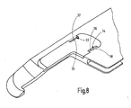
- eine abgewandelte Ausführungsform des Greifers ähnlich
Fig. 2 in perspektivischer Darstellung - Fig. 9
- die Ausführungsform des Greifers gemäß
Figur 8 - Fig. 10
- eine abgewandelte Ausführungsform des Greifers in ausschnittsweiser Seitenansicht,
- Fig. 11
- den Greifer nach
Figur 10 - Fig. 12
- den Greifer nach
Figur 10
- Fig. 1
- a tufting device with gripper bar in a schematic representation,
- Fig. 2
- a gripper, the gripper bar after
Fig. 1 in a fragmentary perspective view, - Fig. 3
- the gripper after
Fig. 2 in a view from below, - Fig. 4
- the gripper after
Fig. 2 without cutting insert in a side view, - Fig. 5
- the gripper after
Fig. 4 with cutting insert in a side view, - Fig. 6
- the gripper after
Fig. 5 , cut along the line VI-VI, - Fig. 7
- an enlarged section of the
Fig. 6 . - Fig. 8
- a modified embodiment of the gripper similar
Fig. 2 in perspective view - Fig. 9
- the embodiment of the gripper according to
FIG. 8 in a fragmentary perspective view, - Fig. 10
- a modified embodiment of the gripper in a sectional side view,
- Fig. 11
- the gripper after
FIG. 10 in a partial view from below and - Fig. 12
- the gripper after
FIG. 10 in perspective fragmentary view.
In
Der in
Der Schlingenaufnahmeabschnitt 15 weist eine gerade untere Kante 19 bzw. Schmalseite auf, auf der die Schlingen 20 gleiten können, wie aus
Die Ausnehmung 22 weist vorzugsweise eine im Wesentlichen einheitliche Tiefe auf. Ihr Umriss entspricht dem eines an seinen Ecken abgerundeten Rechtecks, dem durch die Kanten 19, 21 ein kleineres rechteckiges Stück abgetrennt ist. Somit hat die Vertiefung 22 einen ersten längeren schmalen Abschnitt 23 und einen zweiten kürzeren breiteren Abschnitt 24.The
In der Vertiefung 22 sitzt ein Schneideinsatz 10, wie er aus den
Bei einer anderen Ausführungsform (nicht dargestellt), einem Cut-Pile-Looper, weist die Flachseite 11, welche die Ausnehmung 22 nicht enthält die Schrägfläche 28 auf.In another embodiment (not shown), a cut-pile looper, the
Der Schneideinsatz 10 weist eine Schneidkante 29 auf, die aus den
Es ist auch möglich, dass die Schneidkante 29 des Schneideinsatzes 10 die Kante 19 des Greiferkörpers 9 überragt und somit dieser vorsteht. Dies ist in
Der Umriss des Schneideinsatzes 10 stimmt mit dem Rand der Ausnehmung 22 überein. Somit sitzt der Schneideinsatz 10 im Wesentlichen spielfrei in der Ausnehmung 22. Zur Befestigung des Schneideinsatzes weist dieser an seinem Halteabschnitt 32 Aussparungen 33, 34 auf, siehe dazu
Zur Befestigung des Schneideinsatzes 10 ist der Greiferkörper 9 mit dem Schneideinsatz 10 verstemmt. Dazu sind Randbereiche der Ausnehmung 22 plastisch verformt, um die Schrägflächen 35, 36 zu übergreifen. Die so gebildeten Verformungsbereiche 37, 38 halten den Schneideinsatz 10 somit formschlüssig in der Ausnehmung 22. Dies geht insbesondere aus
Der insoweit beschriebene Greifer 3 arbeitet wie folgt:The
In Betrieb nimmt er mit seinem Ende 16 Schlingen 20 auf, die über die Kante 19 laufen. Dazu wird die Greiferbarre 2 in der Regel rhythmisch bewegt. Die Schlingen 20 gelangen auf die Schneidkante 29 des Schneideinsatzes 10. Dort werden sie von dem ebenfalls entsprechend rhythmisch bewegten Messer 6 aufgeschnitten. Das Messer 6 kann dabei z.B. über die Schrägfläche 27 laufen, wodurch verhindert wird, dass es stumpf auf eine Kante des Schneideinsatzes 10 stößt.In operation, he takes with his
Der Greiferkörper 9 und der Schneideinsatz 10 können, wie erwähnt, aus unterschiedlichen Materialien bestehen. Sie können außerdem unterschiedlich beschichtet sein. Beispielsweise kann der Greiferkörper 9 mit einer reibungsmindernden Kunststoffbeschichtung, beispielsweise einer Teflonbeschichtung, versehen sein. Dagegen kann der Schneideinsatz 10 mit einer verschleißmindernden Beschichtung wie beispielsweise einer metallischen Hartstoffbeschichtung, wie Titannitrid, Titankarbid oder dergleichen, versehen sein.The
Bei dem vorstehend beschriebenen Ausführungsbeispiel wird die axiale Sicherung des Schneideinsatzes 10 in der Ausnehmung 22 bewirkt, in dem der Schneideinsatz 10 passgenau in die Ausnehmung 22 passt. Es ist darüber hinaus möglich, wie
In Nachbarschaft der Kante 41 ist der Rand der Ausnehmung 17 mit einer Schrägfläche 48 versehen, die aus
Bei der in
Durch die Schrägfläche 48 wird vermieden, dass der Faden 47 an der Kante 41 oder dem Rand der Ausnehmung 17 hängen bleibt. Außerdem geht die Ausnehmung 17 mit einem gerundeten Wandabschnitt 49 in die Kante 19 über. Durch diese Abschrägung oder Rundung 49 wird ebenfalls verhindert, dass der Faden hängen bleibt oder beschädigt wird.The
Ein Greifer 3 für eine Tuftingmaschine weist einen Greiferkörper 9 auf, der eine Ausnehmung 22 für einen Schneideinsatz 10, vorzugsweise aus Hartmetall, aufweist. Zur Verbindung des Schneideinsatzes 10 mit dem Greiferkörper 9 sind formschlüssig wirkende Verbindungsmittel vorgesehen. Diese werden in der einfachsten Ausführungsform durch Verformungsbereiche 37, 38 gebildet, die an dem Greiferkörper 9 ausgebildet sich und passende Aussparungen 33, 34 des Schneideinsatzes 10 übergreifen.A
- 11
- TuftingsystemTuftingsystem
- 22
- Greiferbarregripper bar
- 33
- Greifergrab
- 44
- Nadelbarreneedle bar
- 55
- Tuftingnadeltufting
- 66
- Messerknife
- 77
- Trägermaterialsupport material
- 88th
- Florfädenpile threads
- 99
- Greiferkörpergripper body
- 1010
- Schneideinsatzcutting insert
- 1111
- Seitenflächeside surface
- 1212
- Seitenflächeside surface
- 1313
- Halteabschnittholding section
- 1414
- Mittelabschnittmidsection
- 1515
- Schlingenaufnahmeabschnitt/ GreiferabschnittLoop receiving section / gripper section
- 1616
- EndeThe End
- 1717
- Ausnehmungrecess
- 1818
- Führungsausnehmungguide recess
- 1919
- Kante/SchmalseiteEdge / short side
- 2020
- Schlingeloop
- 2121
- Kanteedge
- 2222
- Ausnehmungrecess
- 2323
- Abschnittsection
- 2424
- Abschnittsection
- 2525
- Flachseiteflat side
- 2626
- Flachseiteflat side
- 2727
- Schrägflächesloping surface
- 2828
- Schrägflächesloping surface
- 2929
- Schneidkantecutting edge
- 3030
- Kantenabschnittedge portion
- 3131
- Abschnittsection
- 3232
- Abschnittsection
- 3333
- Aussparungrecess
- 3434
- Aussparungrecess
- 3535
- Schrägflächesloping surface
- 3636
- Schrägflächesloping surface
- 3737
- Verformungsbereichdeformation zone
- 3838
- Verformungsbereichdeformation zone
- 3939
- Ramperamp
- 4040
- Unterseitebottom
- 4141
- Kanteedge
- 4242
- Seitenflächeside surface
- 4343
- StelleJob
- 4444
- stumpfer Winkeldull angle
- 4545
- Abschnittsection
- 4646
- Delledent
- 4747
- Fadenthread
- 4848
- Schrägflächesloping surface
- 4949
- Wandabschnittwall section
Claims (15)
mit einem Greiferkörper (9), der einen Greiferabschnitt (15) zur Aufnahme von Fadenschlingen (20) aufweist, und
mit einem Schneideinsatz (10), der in eine Ausnehmung (22) des Greiferkörpers (9) eingesetzt und in der Ausnehmung (22) formschlüssig gesichert ist.Gripper (3) for tufting machine,
with a gripper body (9) having a gripper portion (15) for receiving thread loops (20), and
with a cutting insert (10) which is inserted into a recess (22) of the gripper body (9) and secured in a form-fitting manner in the recess (22).
Priority Applications (2)
| Application Number | Priority Date | Filing Date | Title |
|---|---|---|---|
| PL08001407T PL1953290T3 (en) | 2007-02-01 | 2008-01-25 | Gripper for a tufting machine |
| EP08001407A EP1953290B1 (en) | 2007-02-01 | 2008-01-25 | Gripper for a tufting machine |
Applications Claiming Priority (2)
| Application Number | Priority Date | Filing Date | Title |
|---|---|---|---|
| EP07002185A EP1953289A1 (en) | 2007-02-01 | 2007-02-01 | Hook for a tufting machine |
| EP08001407A EP1953290B1 (en) | 2007-02-01 | 2008-01-25 | Gripper for a tufting machine |
Publications (2)
| Publication Number | Publication Date |
|---|---|
| EP1953290A1 true EP1953290A1 (en) | 2008-08-06 |
| EP1953290B1 EP1953290B1 (en) | 2013-01-09 |
Family
ID=38235328
Family Applications (2)
| Application Number | Title | Priority Date | Filing Date |
|---|---|---|---|
| EP07002185A Withdrawn EP1953289A1 (en) | 2007-02-01 | 2007-02-01 | Hook for a tufting machine |
| EP08001407A Not-in-force EP1953290B1 (en) | 2007-02-01 | 2008-01-25 | Gripper for a tufting machine |
Family Applications Before (1)
| Application Number | Title | Priority Date | Filing Date |
|---|---|---|---|
| EP07002185A Withdrawn EP1953289A1 (en) | 2007-02-01 | 2007-02-01 | Hook for a tufting machine |
Country Status (6)
| Country | Link |
|---|---|
| US (1) | US7717049B2 (en) |
| EP (2) | EP1953289A1 (en) |
| JP (1) | JP5440970B2 (en) |
| KR (1) | KR100985011B1 (en) |
| CN (1) | CN101240488B (en) |
| PL (1) | PL1953290T3 (en) |
Cited By (5)
| Publication number | Priority date | Publication date | Assignee | Title |
|---|---|---|---|---|
| EP2412860A1 (en) | 2010-07-28 | 2012-02-01 | Groz-Beckert KG | Looper with double insert body |
| EP2412859A1 (en) | 2010-07-28 | 2012-02-01 | Groz-Beckert KG | Tufting gripper with spring bearing of an insert |
| DE102014102801A1 (en) | 2014-03-03 | 2015-09-03 | Groz-Beckert Kg | Profiled loop grab |
| EP3406781A1 (en) | 2017-05-22 | 2018-11-28 | Groz-Beckert KG | Gripper for tufting machine |
| US11807971B2 (en) | 2019-11-07 | 2023-11-07 | Vandewiele Sweden Ab | Tufting tool with insert |
Families Citing this family (9)
| Publication number | Priority date | Publication date | Assignee | Title |
|---|---|---|---|---|
| US8359989B2 (en) | 2008-02-15 | 2013-01-29 | Card-Monroe Corp. | Stitch distribution control system for tufting machines |
| US8141505B2 (en) | 2008-02-15 | 2012-03-27 | Card-Monroe Corp. | Yarn color placement system |
| EP2182103A1 (en) * | 2008-10-29 | 2010-05-05 | Groz-Beckert KG | Tool for manufacturing textile surfaces |
| DE102015101495B4 (en) * | 2015-02-03 | 2016-08-25 | Groz-Beckert Kg | Loop grab with retaining element |
| US11193225B2 (en) | 2016-03-17 | 2021-12-07 | Card-Monroe Corp. | Tufting machine and method of tufting |
| US10233578B2 (en) | 2016-03-17 | 2019-03-19 | Card-Monroe Corp. | Tufting machine and method of tufting |
| GB2579339B (en) * | 2018-10-04 | 2021-07-07 | Vandewiele Nv | A hook for a tufting machine |
| CN114729486B (en) * | 2019-10-29 | 2023-06-30 | 范德威尔瑞典公司 | Tufting tool module |
| US11585029B2 (en) | 2021-02-16 | 2023-02-21 | Card-Monroe Corp. | Tufting maching and method of tufting |
Citations (10)
| Publication number | Priority date | Publication date | Assignee | Title |
|---|---|---|---|---|
| US1909530A (en) * | 1929-10-02 | 1933-05-16 | Valway Rug Mills Inc | Tufting machine looper and cutter |
| FR767333A (en) * | 1933-01-21 | 1934-07-16 | Device for making carpets on vibrating shuttle sewing machines | |
| US2492711A (en) * | 1944-06-28 | 1949-12-27 | Charles L Pickworth | Tuft forming sewing machine |
| US2800096A (en) | 1954-07-14 | 1957-07-23 | American Safety Razor Corp | Tufter hook |
| GB782079A (en) | 1955-01-05 | 1957-08-28 | American Safety Razor Corp | Improvements in or relating to tufter hook |
| FR1473511A (en) * | 1964-02-11 | 1967-03-17 | Dock Grinding & Engineering Co | Cutting Tool for Stitched Tuft Carpet Making Machines |
| DE2341567A1 (en) | 1973-08-17 | 1975-02-27 | Rolf Doerschel | Carpet tufting machine looper tool - has hard metal plates with cutting edges soldered into place to lengthen tool life |
| DE2823408A1 (en) | 1977-06-02 | 1978-12-07 | Yoshio Yamamoto | LOOSE CUTTERS FOR TUFTING MACHINES |
| DE3709977A1 (en) * | 1987-03-26 | 1988-10-13 | Carl Schlemper Gmbh & Co Kg | Loop gripper for tufting machines |
| DE4315802A1 (en) * | 1993-05-13 | 1994-11-17 | Stutznaecker Emil Naehmasch | Sewing machine, especially multi-needle double chain-stitch machine |
Family Cites Families (12)
| Publication number | Priority date | Publication date | Assignee | Title |
|---|---|---|---|---|
| US2090021A (en) | 1935-06-18 | 1937-08-17 | A & M Karagheusian Inc | Pile cutter |
| US3152563A (en) * | 1961-03-15 | 1964-10-13 | Lees & Sons Co James | Tufting machine and looper for producing j-loops |
| CA955127A (en) * | 1970-08-26 | 1974-09-24 | Teijin Limited | Knives for the gru-gru cutter |
| JPS5483969U (en) * | 1977-11-24 | 1979-06-14 | ||
| US4353317A (en) * | 1982-02-04 | 1982-10-12 | Spencer Wright Industries, Inc. | Method and apparatus for tufting high and low pile in the same row of stitching |
| JPS59179861A (en) * | 1983-03-31 | 1984-10-12 | 仲 行雄 | Looper for tufting machine |
| JPS6147096U (en) * | 1984-08-30 | 1986-03-29 | 京セラ株式会社 | Single blade looper |
| JPS61183994U (en) * | 1985-05-02 | 1986-11-17 | ||
| DE4435723C2 (en) * | 1994-10-06 | 1996-08-08 | Zimmermann Jos Gmbh & Co Kg | Tufting process and tufting device suitable for carrying out this process |
| KR19980014467U (en) * | 1998-03-18 | 1998-06-05 | 박병모 | Rotary blade for cutting fabric |
| CN2373468Y (en) * | 1999-06-17 | 2000-04-12 | 林忠义 | Bearded needle cutting knife fitting device tufting machine |
| US6404660B1 (en) * | 1999-12-23 | 2002-06-11 | Rambus, Inc. | Semiconductor package with a controlled impedance bus and method of forming same |
-
2007
- 2007-02-01 EP EP07002185A patent/EP1953289A1/en not_active Withdrawn
-
2008
- 2008-01-25 PL PL08001407T patent/PL1953290T3/en unknown
- 2008-01-25 EP EP08001407A patent/EP1953290B1/en not_active Not-in-force
- 2008-01-31 US US12/010,961 patent/US7717049B2/en not_active Expired - Fee Related
- 2008-01-31 KR KR1020080009926A patent/KR100985011B1/en not_active IP Right Cessation
- 2008-01-31 CN CN2008100881117A patent/CN101240488B/en not_active Expired - Fee Related
- 2008-02-01 JP JP2008022693A patent/JP5440970B2/en not_active Expired - Fee Related
Patent Citations (11)
| Publication number | Priority date | Publication date | Assignee | Title |
|---|---|---|---|---|
| US1909530A (en) * | 1929-10-02 | 1933-05-16 | Valway Rug Mills Inc | Tufting machine looper and cutter |
| FR767333A (en) * | 1933-01-21 | 1934-07-16 | Device for making carpets on vibrating shuttle sewing machines | |
| US2492711A (en) * | 1944-06-28 | 1949-12-27 | Charles L Pickworth | Tuft forming sewing machine |
| US2800096A (en) | 1954-07-14 | 1957-07-23 | American Safety Razor Corp | Tufter hook |
| GB782079A (en) | 1955-01-05 | 1957-08-28 | American Safety Razor Corp | Improvements in or relating to tufter hook |
| FR1473511A (en) * | 1964-02-11 | 1967-03-17 | Dock Grinding & Engineering Co | Cutting Tool for Stitched Tuft Carpet Making Machines |
| DE2341567A1 (en) | 1973-08-17 | 1975-02-27 | Rolf Doerschel | Carpet tufting machine looper tool - has hard metal plates with cutting edges soldered into place to lengthen tool life |
| DE2823408A1 (en) | 1977-06-02 | 1978-12-07 | Yoshio Yamamoto | LOOSE CUTTERS FOR TUFTING MACHINES |
| FR2393096A1 (en) | 1977-06-02 | 1978-12-29 | Yamamoto Yoshio | LOOPER FOR TOUFFETING MACHINES |
| DE3709977A1 (en) * | 1987-03-26 | 1988-10-13 | Carl Schlemper Gmbh & Co Kg | Loop gripper for tufting machines |
| DE4315802A1 (en) * | 1993-05-13 | 1994-11-17 | Stutznaecker Emil Naehmasch | Sewing machine, especially multi-needle double chain-stitch machine |
Cited By (10)
| Publication number | Priority date | Publication date | Assignee | Title |
|---|---|---|---|---|
| EP2412860A1 (en) | 2010-07-28 | 2012-02-01 | Groz-Beckert KG | Looper with double insert body |
| EP2412859A1 (en) | 2010-07-28 | 2012-02-01 | Groz-Beckert KG | Tufting gripper with spring bearing of an insert |
| US8302546B2 (en) | 2010-07-28 | 2012-11-06 | Groz-Beckert Kg | Tufting gripper with spring-biased support of an insert |
| DE102014102801A1 (en) | 2014-03-03 | 2015-09-03 | Groz-Beckert Kg | Profiled loop grab |
| DE102014102801B4 (en) * | 2014-03-03 | 2015-11-05 | Groz-Beckert Kg | Profiled loop grab |
| CN106536806A (en) * | 2014-03-03 | 2017-03-22 | 格罗兹-贝克特公司 | Profiled pile cutter |
| CN106536806B (en) * | 2014-03-03 | 2019-03-19 | 格罗兹-贝克特公司 | Contoured villus cutter |
| EP3406781A1 (en) | 2017-05-22 | 2018-11-28 | Groz-Beckert KG | Gripper for tufting machine |
| US10731282B2 (en) | 2017-05-22 | 2020-08-04 | Groz-Beckert Kg | Gripper for a tufting machine |
| US11807971B2 (en) | 2019-11-07 | 2023-11-07 | Vandewiele Sweden Ab | Tufting tool with insert |
Also Published As
| Publication number | Publication date |
|---|---|
| US20080264314A1 (en) | 2008-10-30 |
| KR20080072552A (en) | 2008-08-06 |
| CN101240488A (en) | 2008-08-13 |
| EP1953289A1 (en) | 2008-08-06 |
| CN101240488B (en) | 2011-11-16 |
| JP5440970B2 (en) | 2014-03-12 |
| JP2008190109A (en) | 2008-08-21 |
| EP1953290B1 (en) | 2013-01-09 |
| US7717049B2 (en) | 2010-05-18 |
| KR100985011B1 (en) | 2010-10-05 |
| PL1953290T3 (en) | 2013-03-29 |
Similar Documents
| Publication | Publication Date | Title |
|---|---|---|
| EP1953290B1 (en) | Gripper for a tufting machine | |
| EP1826307B1 (en) | Looper for tufting machine | |
| EP1826306B1 (en) | Looper device for a tufting machine | |
| EP2101943B1 (en) | Tool holder, particularly for a burring tool, and cutting element for a tool holder | |
| EP3114265B1 (en) | Profiled pile cutter | |
| EP1908871B1 (en) | Looper for tufting machine | |
| DE2834738C2 (en) | Needle for tufting machines | |
| DE2823408A1 (en) | LOOSE CUTTERS FOR TUFTING MACHINES | |
| DE60301914T2 (en) | Cutting insert for drills | |
| DE3325767C1 (en) | Slider needle for stitch-forming textile machines | |
| DE2615018C2 (en) | Tufting needle | |
| WO2005095703A1 (en) | Embossed tufting needle | |
| EP2896732B1 (en) | Sewing needle with double cording | |
| EP2412860A1 (en) | Looper with double insert body | |
| DE7614289U1 (en) | NEEDLE FOR TUFTING MACHINES | |
| CH662834A5 (en) | THREAD GUIDE FOR A FLAT KNITTING MACHINE AND A FLAT KNITTING MACHINE. | |
| DE69803142T3 (en) | Slider needle for knitting machine | |
| EP1127973B1 (en) | Sewing needle for multidirectional sewing | |
| EP2999815B1 (en) | Sliding-tongue needle | |
| DE602004011154T2 (en) | Method for the non-abrasive production of a surgical needle | |
| DE2745793A1 (en) | TUFTING MACHINE | |
| EP1416078B1 (en) | Stitch forming element for weft or warp knitting machine | |
| EP3406781A1 (en) | Gripper for tufting machine | |
| DE602005004184T2 (en) | Manufacturing method for a surgical needle | |
| EP1887117B1 (en) | Latch needle for stitch forming textile machine |
Legal Events
| Date | Code | Title | Description |
|---|---|---|---|
| PUAI | Public reference made under article 153(3) epc to a published international application that has entered the european phase |
Free format text: ORIGINAL CODE: 0009012 |
|
| AK | Designated contracting states |
Kind code of ref document: A1 Designated state(s): AT BE BG CH CY CZ DE DK EE ES FI FR GB GR HR HU IE IS IT LI LT LU LV MC MT NL NO PL PT RO SE SI SK TR |
|
| AX | Request for extension of the european patent |
Extension state: AL BA MK RS |
|
| 17P | Request for examination filed |
Effective date: 20080905 |
|
| 17Q | First examination report despatched |
Effective date: 20081021 |
|
| AKX | Designation fees paid |
Designated state(s): AT BE BG CH CY CZ DE DK EE ES FI FR GB GR HR HU IE IS IT LI LT LU LV MC MT NL NO PL PT RO SE SI SK TR |
|
| GRAP | Despatch of communication of intention to grant a patent |
Free format text: ORIGINAL CODE: EPIDOSNIGR1 |
|
| GRAS | Grant fee paid |
Free format text: ORIGINAL CODE: EPIDOSNIGR3 |
|
| GRAA | (expected) grant |
Free format text: ORIGINAL CODE: 0009210 |
|
| AK | Designated contracting states |
Kind code of ref document: B1 Designated state(s): AT BE BG CH CY CZ DE DK EE ES FI FR GB GR HR HU IE IS IT LI LT LU LV MC MT NL NO PL PT RO SE SI SK TR |
|
| REG | Reference to a national code |
Ref country code: GB Ref legal event code: FG4D Free format text: NOT ENGLISH |
|
| REG | Reference to a national code |
Ref country code: AT Ref legal event code: REF Ref document number: 592830 Country of ref document: AT Kind code of ref document: T Effective date: 20130115 Ref country code: CH Ref legal event code: EP |
|
| REG | Reference to a national code |
Ref country code: IE Ref legal event code: FG4D Free format text: LANGUAGE OF EP DOCUMENT: GERMAN |
|
| REG | Reference to a national code |
Ref country code: DE Ref legal event code: R096 Ref document number: 502008009037 Country of ref document: DE Effective date: 20130314 |
|
| REG | Reference to a national code |
Ref country code: PL Ref legal event code: T3 |
|
| REG | Reference to a national code |
Ref country code: NL Ref legal event code: T3 |
|
| PG25 | Lapsed in a contracting state [announced via postgrant information from national office to epo] |
Ref country code: SI Free format text: LAPSE BECAUSE OF FAILURE TO SUBMIT A TRANSLATION OF THE DESCRIPTION OR TO PAY THE FEE WITHIN THE PRESCRIBED TIME-LIMIT Effective date: 20130109 |
|
| REG | Reference to a national code |
Ref country code: SK Ref legal event code: T3 Ref document number: E 13715 Country of ref document: SK |
|
| REG | Reference to a national code |
Ref country code: LT Ref legal event code: MG4D |
|
| PG25 | Lapsed in a contracting state [announced via postgrant information from national office to epo] |
Ref country code: ES Free format text: LAPSE BECAUSE OF FAILURE TO SUBMIT A TRANSLATION OF THE DESCRIPTION OR TO PAY THE FEE WITHIN THE PRESCRIBED TIME-LIMIT Effective date: 20130420 Ref country code: IS Free format text: LAPSE BECAUSE OF FAILURE TO SUBMIT A TRANSLATION OF THE DESCRIPTION OR TO PAY THE FEE WITHIN THE PRESCRIBED TIME-LIMIT Effective date: 20130509 Ref country code: NO Free format text: LAPSE BECAUSE OF FAILURE TO SUBMIT A TRANSLATION OF THE DESCRIPTION OR TO PAY THE FEE WITHIN THE PRESCRIBED TIME-LIMIT Effective date: 20130409 Ref country code: CY Free format text: LAPSE BECAUSE OF FAILURE TO SUBMIT A TRANSLATION OF THE DESCRIPTION OR TO PAY THE FEE WITHIN THE PRESCRIBED TIME-LIMIT Effective date: 20130109 Ref country code: SE Free format text: LAPSE BECAUSE OF FAILURE TO SUBMIT A TRANSLATION OF THE DESCRIPTION OR TO PAY THE FEE WITHIN THE PRESCRIBED TIME-LIMIT Effective date: 20130109 Ref country code: LT Free format text: LAPSE BECAUSE OF FAILURE TO SUBMIT A TRANSLATION OF THE DESCRIPTION OR TO PAY THE FEE WITHIN THE PRESCRIBED TIME-LIMIT Effective date: 20130109 Ref country code: BG Free format text: LAPSE BECAUSE OF FAILURE TO SUBMIT A TRANSLATION OF THE DESCRIPTION OR TO PAY THE FEE WITHIN THE PRESCRIBED TIME-LIMIT Effective date: 20130409 |
|
| PG25 | Lapsed in a contracting state [announced via postgrant information from national office to epo] |
Ref country code: MC Free format text: LAPSE BECAUSE OF NON-PAYMENT OF DUE FEES Effective date: 20130131 Ref country code: FI Free format text: LAPSE BECAUSE OF FAILURE TO SUBMIT A TRANSLATION OF THE DESCRIPTION OR TO PAY THE FEE WITHIN THE PRESCRIBED TIME-LIMIT Effective date: 20130109 Ref country code: PT Free format text: LAPSE BECAUSE OF FAILURE TO SUBMIT A TRANSLATION OF THE DESCRIPTION OR TO PAY THE FEE WITHIN THE PRESCRIBED TIME-LIMIT Effective date: 20130509 Ref country code: LV Free format text: LAPSE BECAUSE OF FAILURE TO SUBMIT A TRANSLATION OF THE DESCRIPTION OR TO PAY THE FEE WITHIN THE PRESCRIBED TIME-LIMIT Effective date: 20130109 Ref country code: GR Free format text: LAPSE BECAUSE OF FAILURE TO SUBMIT A TRANSLATION OF THE DESCRIPTION OR TO PAY THE FEE WITHIN THE PRESCRIBED TIME-LIMIT Effective date: 20130410 |
|
| REG | Reference to a national code |
Ref country code: CH Ref legal event code: PL |
|
| PG25 | Lapsed in a contracting state [announced via postgrant information from national office to epo] |
Ref country code: HR Free format text: LAPSE BECAUSE OF FAILURE TO SUBMIT A TRANSLATION OF THE DESCRIPTION OR TO PAY THE FEE WITHIN THE PRESCRIBED TIME-LIMIT Effective date: 20130109 |
|
| REG | Reference to a national code |
Ref country code: IE Ref legal event code: MM4A |
|
| PG25 | Lapsed in a contracting state [announced via postgrant information from national office to epo] |
Ref country code: DK Free format text: LAPSE BECAUSE OF FAILURE TO SUBMIT A TRANSLATION OF THE DESCRIPTION OR TO PAY THE FEE WITHIN THE PRESCRIBED TIME-LIMIT Effective date: 20130109 Ref country code: CH Free format text: LAPSE BECAUSE OF NON-PAYMENT OF DUE FEES Effective date: 20130131 Ref country code: RO Free format text: LAPSE BECAUSE OF FAILURE TO SUBMIT A TRANSLATION OF THE DESCRIPTION OR TO PAY THE FEE WITHIN THE PRESCRIBED TIME-LIMIT Effective date: 20130109 Ref country code: LI Free format text: LAPSE BECAUSE OF NON-PAYMENT OF DUE FEES Effective date: 20130131 Ref country code: EE Free format text: LAPSE BECAUSE OF FAILURE TO SUBMIT A TRANSLATION OF THE DESCRIPTION OR TO PAY THE FEE WITHIN THE PRESCRIBED TIME-LIMIT Effective date: 20130109 |
|
| PLBE | No opposition filed within time limit |
Free format text: ORIGINAL CODE: 0009261 |
|
| STAA | Information on the status of an ep patent application or granted ep patent |
Free format text: STATUS: NO OPPOSITION FILED WITHIN TIME LIMIT |
|
| 26N | No opposition filed |
Effective date: 20131010 |
|
| REG | Reference to a national code |
Ref country code: DE Ref legal event code: R097 Ref document number: 502008009037 Country of ref document: DE Effective date: 20131010 |
|
| PG25 | Lapsed in a contracting state [announced via postgrant information from national office to epo] |
Ref country code: IE Free format text: LAPSE BECAUSE OF NON-PAYMENT OF DUE FEES Effective date: 20130125 |
|
| PG25 | Lapsed in a contracting state [announced via postgrant information from national office to epo] |
Ref country code: MT Free format text: LAPSE BECAUSE OF FAILURE TO SUBMIT A TRANSLATION OF THE DESCRIPTION OR TO PAY THE FEE WITHIN THE PRESCRIBED TIME-LIMIT Effective date: 20130109 |
|
| PGFP | Annual fee paid to national office [announced via postgrant information from national office to epo] |
Ref country code: SK Payment date: 20150122 Year of fee payment: 8 |
|
| PG25 | Lapsed in a contracting state [announced via postgrant information from national office to epo] |
Ref country code: LU Free format text: LAPSE BECAUSE OF NON-PAYMENT OF DUE FEES Effective date: 20130125 Ref country code: HU Free format text: LAPSE BECAUSE OF FAILURE TO SUBMIT A TRANSLATION OF THE DESCRIPTION OR TO PAY THE FEE WITHIN THE PRESCRIBED TIME-LIMIT; INVALID AB INITIO Effective date: 20080125 |
|
| REG | Reference to a national code |
Ref country code: FR Ref legal event code: PLFP Year of fee payment: 9 |
|
| PGFP | Annual fee paid to national office [announced via postgrant information from national office to epo] |
Ref country code: FR Payment date: 20151208 Year of fee payment: 9 Ref country code: PL Payment date: 20151130 Year of fee payment: 9 |
|
| PGFP | Annual fee paid to national office [announced via postgrant information from national office to epo] |
Ref country code: IT Payment date: 20160127 Year of fee payment: 9 Ref country code: CZ Payment date: 20160105 Year of fee payment: 9 |
|
| REG | Reference to a national code |
Ref country code: SK Ref legal event code: MM4A Ref document number: E 13715 Country of ref document: SK Effective date: 20160125 |
|
| PG25 | Lapsed in a contracting state [announced via postgrant information from national office to epo] |
Ref country code: SK Free format text: LAPSE BECAUSE OF NON-PAYMENT OF DUE FEES Effective date: 20160125 |
|
| PGFP | Annual fee paid to national office [announced via postgrant information from national office to epo] |
Ref country code: NL Payment date: 20170110 Year of fee payment: 10 |
|
| PGFP | Annual fee paid to national office [announced via postgrant information from national office to epo] |
Ref country code: AT Payment date: 20161223 Year of fee payment: 10 |
|
| PGFP | Annual fee paid to national office [announced via postgrant information from national office to epo] |
Ref country code: TR Payment date: 20170105 Year of fee payment: 10 |
|
| REG | Reference to a national code |
Ref country code: FR Ref legal event code: ST Effective date: 20170929 |
|
| PG25 | Lapsed in a contracting state [announced via postgrant information from national office to epo] |
Ref country code: CZ Free format text: LAPSE BECAUSE OF NON-PAYMENT OF DUE FEES Effective date: 20170125 Ref country code: FR Free format text: LAPSE BECAUSE OF NON-PAYMENT OF DUE FEES Effective date: 20170131 |
|
| PG25 | Lapsed in a contracting state [announced via postgrant information from national office to epo] |
Ref country code: IT Free format text: LAPSE BECAUSE OF NON-PAYMENT OF DUE FEES Effective date: 20170125 |
|
| PG25 | Lapsed in a contracting state [announced via postgrant information from national office to epo] |
Ref country code: PL Free format text: LAPSE BECAUSE OF NON-PAYMENT OF DUE FEES Effective date: 20170125 |
|
| REG | Reference to a national code |
Ref country code: NL Ref legal event code: MM Effective date: 20180201 |
|
| REG | Reference to a national code |
Ref country code: AT Ref legal event code: MM01 Ref document number: 592830 Country of ref document: AT Kind code of ref document: T Effective date: 20180125 |
|
| PG25 | Lapsed in a contracting state [announced via postgrant information from national office to epo] |
Ref country code: NL Free format text: LAPSE BECAUSE OF NON-PAYMENT OF DUE FEES Effective date: 20180201 Ref country code: AT Free format text: LAPSE BECAUSE OF NON-PAYMENT OF DUE FEES Effective date: 20180125 |
|
| PGFP | Annual fee paid to national office [announced via postgrant information from national office to epo] |
Ref country code: BE Payment date: 20191217 Year of fee payment: 13 |
|
| PGFP | Annual fee paid to national office [announced via postgrant information from national office to epo] |
Ref country code: DE Payment date: 20200131 Year of fee payment: 13 Ref country code: GB Payment date: 20200115 Year of fee payment: 13 |
|
| REG | Reference to a national code |
Ref country code: DE Ref legal event code: R119 Ref document number: 502008009037 Country of ref document: DE |
|
| GBPC | Gb: european patent ceased through non-payment of renewal fee |
Effective date: 20210125 |
|
| REG | Reference to a national code |
Ref country code: BE Ref legal event code: MM Effective date: 20210131 |
|
| PG25 | Lapsed in a contracting state [announced via postgrant information from national office to epo] |
Ref country code: GB Free format text: LAPSE BECAUSE OF NON-PAYMENT OF DUE FEES Effective date: 20210125 Ref country code: DE Free format text: LAPSE BECAUSE OF NON-PAYMENT OF DUE FEES Effective date: 20210803 |
|
| PG25 | Lapsed in a contracting state [announced via postgrant information from national office to epo] |
Ref country code: TR Free format text: LAPSE BECAUSE OF NON-PAYMENT OF DUE FEES Effective date: 20180125 |
|
| PG25 | Lapsed in a contracting state [announced via postgrant information from national office to epo] |
Ref country code: BE Free format text: LAPSE BECAUSE OF NON-PAYMENT OF DUE FEES Effective date: 20210131 |