EP1952772A1 - Instrument zum operativen Entfernen einer defekten Herzklappe. - Google Patents
Instrument zum operativen Entfernen einer defekten Herzklappe. Download PDFInfo
- Publication number
- EP1952772A1 EP1952772A1 EP08001034A EP08001034A EP1952772A1 EP 1952772 A1 EP1952772 A1 EP 1952772A1 EP 08001034 A EP08001034 A EP 08001034A EP 08001034 A EP08001034 A EP 08001034A EP 1952772 A1 EP1952772 A1 EP 1952772A1
- Authority
- EP
- European Patent Office
- Prior art keywords
- guide rod
- cutting
- heart valve
- tool
- cutting ring
- Prior art date
- Legal status (The legal status is an assumption and is not a legal conclusion. Google has not performed a legal analysis and makes no representation as to the accuracy of the status listed.)
- Granted
Links
Images

Classifications
-
- A—HUMAN NECESSITIES
- A61—MEDICAL OR VETERINARY SCIENCE; HYGIENE
- A61B—DIAGNOSIS; SURGERY; IDENTIFICATION
- A61B17/00—Surgical instruments, devices or methods
- A61B17/32—Surgical cutting instruments
- A61B17/3205—Excision instruments
- A61B17/3207—Atherectomy devices working by cutting or abrading; Similar devices specially adapted for non-vascular obstructions
- A61B17/320725—Atherectomy devices working by cutting or abrading; Similar devices specially adapted for non-vascular obstructions with radially expandable cutting or abrading elements
-
- A—HUMAN NECESSITIES
- A61—MEDICAL OR VETERINARY SCIENCE; HYGIENE
- A61B—DIAGNOSIS; SURGERY; IDENTIFICATION
- A61B17/00—Surgical instruments, devices or methods
- A61B17/32—Surgical cutting instruments
- A61B17/320016—Endoscopic cutting instruments, e.g. arthroscopes, resectoscopes
-
- A—HUMAN NECESSITIES
- A61—MEDICAL OR VETERINARY SCIENCE; HYGIENE
- A61B—DIAGNOSIS; SURGERY; IDENTIFICATION
- A61B17/00—Surgical instruments, devices or methods
- A61B17/32—Surgical cutting instruments
- A61B17/3205—Excision instruments
- A61B17/32053—Punch like cutting instruments, e.g. using a cylindrical or oval knife
-
- A—HUMAN NECESSITIES
- A61—MEDICAL OR VETERINARY SCIENCE; HYGIENE
- A61B—DIAGNOSIS; SURGERY; IDENTIFICATION
- A61B17/00—Surgical instruments, devices or methods
- A61B17/00234—Surgical instruments, devices or methods for minimally invasive surgery
- A61B2017/00238—Type of minimally invasive operation
- A61B2017/00243—Type of minimally invasive operation cardiac
-
- A—HUMAN NECESSITIES
- A61—MEDICAL OR VETERINARY SCIENCE; HYGIENE
- A61F—FILTERS IMPLANTABLE INTO BLOOD VESSELS; PROSTHESES; DEVICES PROVIDING PATENCY TO, OR PREVENTING COLLAPSING OF, TUBULAR STRUCTURES OF THE BODY, e.g. STENTS; ORTHOPAEDIC, NURSING OR CONTRACEPTIVE DEVICES; FOMENTATION; TREATMENT OR PROTECTION OF EYES OR EARS; BANDAGES, DRESSINGS OR ABSORBENT PADS; FIRST-AID KITS
- A61F2/00—Filters implantable into blood vessels; Prostheses, i.e. artificial substitutes or replacements for parts of the body; Appliances for connecting them with the body; Devices providing patency to, or preventing collapsing of, tubular structures of the body, e.g. stents
- A61F2/02—Prostheses implantable into the body
- A61F2/24—Heart valves ; Vascular valves, e.g. venous valves; Heart implants, e.g. passive devices for improving the function of the native valve or the heart muscle; Transmyocardial revascularisation [TMR] devices; Valves implantable in the body
Definitions
- the invention relates to an instrument for the surgical removal of a defective heart valve.
- Such instruments are primarily used alone, ie only for removing the defective heart valve, but instruments of this type are also known including additional functions that allow, for example, after removing the defective heart valve with the same instrument and in the same operation a new heart valve to use (see. DE 600 17 189 T2 , there Fig. 1 Reference number 10 with the associated description).
- the invention described below is independent of the respective surgical method by means of which the instrument with its leading (distal) end is brought to the defective heart valve. This applies both to the conventional surgical methods, which require opening the thorax and exposing access to the heart, as well as to the surgical techniques, which, using catheters and endoscopes, enable a heart valve operation with far less strain on the patient (so-called minimally invasive methods).
- the present invention is based on a prior art, as it is for instruments for the surgical removal of a defective heart valve from the US 2005/0075659 A1 is known (see there the 2A to 2C with the corresponding description on page 2 from paragraph [0037]).
- This document discloses concretely in the 2A an instrument having the features of the preamble of claim 1 protection of the present patent application.
- the known instrument has two on one or on a guide rod in an axial distance from each other arranged tool halves, which are each formed in the form of a spiral wound around the tool axis cutting blade.
- the tool halves are axially displaceable relative to each other by means of the guide rod such that their oppositely directed spiral cutting blades cut a positioned between the tool halves defective heart valve.
- the spirally wound cutting blades are radial retractable, that is, the slightly looser wound in their original form blades are wound tight, which reduces the radial distance of the outer winding of the tool axis and a diameter more closely matched to the guide rod contact protection sleeve can be pushed onto the tool halves.
- the contact protection sleeve is pulled axially from the tool halves, so that their spirally wound cutting blades can relax. This increases the radial distances of the spiral windings of the tool axis until a diameter is achieved for the respective outer winding of the cutting blade, which corresponds to the diameter of the excreted defective heart valve and the diameter of the surgically inserted new heart valve.
- the two tool halves are then by means of the guide rod (to which the one tool half is attached) and by means of a guide rod guided on the slide tube (to which the other tool half is attached) to each other moved and cut out the broken heart valve.
- the tool halves can be rotated relative to each other to support the cutting process.
- the object of the present invention is to further develop the above-described generic instruments so that they on the one hand maintain the operational advantages arising from the radially retractable and radially extendable cutting tools and the use of contact protection sleeves, but that they should also ensure on the other hand, that the aforementioned disadvantages are avoided, ie, that no problems occur during the operation when re-pushing the contact protection sleeves on the tool halves, that no interference with the functionality of the instrument by unwanted "chipping" of the defective heart valve occur and that ultimately the generation of a dimensionally circular Cut is ensured when removing the defective heart valve, so that the subsequent surgical insertion and attaching a new heart valve is easily possible.
- each cutting ring half is made of an elastically deformable flat material band (preferably made of super-elastic Nitinol) and each in the vertical format on the in the radial extended state required semicircle diameter is dimensionally preformed that the folding axes of the cutting ring halves are aligned perpendicular to the axis of the guide rod and are fixed in each case by means of the head end of an elastically deformable, but tension and pressure-resistant tab connection extending in the longitudinal direction of the guide rod and the are each mounted with their foot ends on the guide rod, and that each cutting ring half by means of another elastically deformable, tension and pressure-resistant, extending in the longitudinal direction of the guide rod and with its foot end on the guide rod is held, whose head end is articulated in the middle of the semi
- the two tool halves in use, the cutting ring of each mold half is fully extended in the radial direction and set dimensionally to a circle
- uses the idea of the invention the dimensional stability of a flat strip of material that is preformed in terms of manufacturing technology in portrait format on a semicircular arc.
- This pre-deformation is a solidified in the material structure deformation and thus dimensionally stable.
- the dimensional stability is supported by the fixation of the two ends of the jewieligen semicircular arc in the aforementioned folding axes, which in turn are each fixed by the head of a tab connection and fixed in the axial direction to the guide rod of the instrument.
- the respective center of the semicircular arc is axially fixed by a further tab connection to the guide rod of the instrument, so that the axial position and the required dimensional accuracy of the cutting ring diameter of the tool halves is also ensured by means of this tab connections.
- the cutting rings of the tool halves it is in the technical skill of the toolmaker to give the cutting rings by special imprints in the flat strip material (for example by longitudinal and / or transverse corrugations) a special dimensional stability and dimensional accuracy.
- the toolmaker it is also necessary to make a selection of certain material properties and / or to select particular dimensions of the upright format, i. to decide the edgewise cross section of the flat strip material to be processed.
- the invention further includes the teaching, such as the dimensionally stable in use Cutting rings of the respective tool halves are to be retracted to a smaller radial distance from the guide rod of the instrument.
- Essential for this is first that both the cutting ring halves and the tab connections are made of a flat strip material, which despite the required dimensional stability has very good elastic properties (such as super-elastic Nitinol). The pulling of the cutting ring halves is done by an interaction of the tab connections.
- a preferred embodiment of the invention provides that the tabs, whose head ends are hinged to the center of the cutting ring halves, are fixedly mounted with their respective foot ends on the guide rod and that the tabs whose head ends fix the tilt axes, with their respective Foot ends are mounted on or axially displaceable and lockable on the guide rod.
- the aforementioned bearing designs of the respective foot ends of the tabs determine when Einziehvorgang the cutting ring halves a functional sequence, which is characterized in that the tabs that fix the respective center of the semicircular arc of the cutting ring halves remain in its axial position, whereas the tab connections whose head ends with the folding axes of the cutting ring are connected, are axially displaceable and lockable so that they cause a collapse of the cutting ring to his folding axes and simultaneously cause the cutting ring halves to o.dergl about their held in the respective axial position centers to a half-form of a narrow oval. to deform.
- the respective foot-side bearing designs of the tab connections can also be designed differently, without thereby leaving the scope of the teaching of the present invention.
- the foot ends of the tab connections which hold the respective center of the cutting ring halves in position, by means of a sliding block on the guide rod of the instrument to be mounted slidably and lockable.
- the foot ends of the tab connections which fix the tilt axes of the cutting ring are mounted axially displaceably and lockably on the guide rod by means of a sliding block, then functional sequences result during the insertion process of the cutting ring halves, in which the respectively required axial displacement paths are distributed over all tab connections and thus shortened per tab connection.
- the axial displacements usually made possible by sliding blocks on or on the guide bar are achieved by means of a push and push connection rod or by means of coaxial inner or outer sleeves of the guide bar, which extend to the hand Extend handle of the instrument and there are manually operated. This is a common practice for surgical instruments.
- the tab connections configure both in the extended state of the cutting ring and in the retracted state of the cutting ring halves meridians a funnel-shaped body, which can be used in an ideal way to defer a more closely matched in their diameter to the guide rod contact protection sleeve on the cutting edges of the folded cutting ring halves.
- the soft transitions of this funnel shape and the elastic yielding of the tab connections in the radial direction ensure that a contact protection sleeve is repeated at all times (and also during an operation). can be pushed onto the folded tool cutting edges of the instrument and / or withdrawn again.
- a particularly advantageous embodiment of the invention provides according to claim 3, that the instrument for each mold half has its own contact protection sleeve, which is superimposed on the tab connections, which are associated with the respective mold half and the on these tab connections axially and in opposite directions to the contact protection sleeve of the other Tool half is displaceable.
- the tool halves are rotatable with their cutting rings relative to each other such that the defective heart valve is cut by a rotary-punching process.
- Coaxially around the guide rod 10 are two mirror-image mutually formed tool halves 11 and 12, each consisting of a cutting ring 13th and 14 with their respective four tab connections 15 to 18 and 19 to 22, which are each mounted with their foot ends on the guide rod 10.
- the cutting rings are made of an elastically deformable flat strip material and preformed to a geometrically exact circular shape.
- the tab connections are tensile and compression-resistant in the longitudinal direction of the guide rod, but elastically deformable in the radial direction to the guide rod upon the occurrence of corresponding radial force components.
- each mold half links 15 and 17 fix the head side, the folding axes 23 and 24 and 25 and 26.
- the upper mold half 11 is rotated by a rotation of the guide rod 10 on the lower tool half 12 is moved so that by means of a rotary-punching operation, a defective heart valve, which is positioned in the plane 31 between the two mold halves (see Fig. 1 ), and is cut by the intermeshing to form a narrow shear gap cutting rings 13 and 14.
- the functional components for rotating the upper mold half 10 are not shown in the figures for reasons of clarity. They are of conventional design.
Landscapes
- Health & Medical Sciences (AREA)
- Surgery (AREA)
- Life Sciences & Earth Sciences (AREA)
- Medical Informatics (AREA)
- Animal Behavior & Ethology (AREA)
- Engineering & Computer Science (AREA)
- Biomedical Technology (AREA)
- Heart & Thoracic Surgery (AREA)
- Veterinary Medicine (AREA)
- Molecular Biology (AREA)
- Nuclear Medicine, Radiotherapy & Molecular Imaging (AREA)
- General Health & Medical Sciences (AREA)
- Public Health (AREA)
- Orthopedic Medicine & Surgery (AREA)
- Vascular Medicine (AREA)
- Prostheses (AREA)
- External Artificial Organs (AREA)
Abstract
Description
- Die Erfindung betrifft ein Instrument zum operativen Entfernen einer defekten Herzklappe. Solche Instrumente werden vorrangig in Alleinstellung, d.h. nur zum Entfernen der defekten Herzklappe verwendet, aber es sind Instrumente dieser Art auch unter Einschluß zusätzlicher Funktionen bekannt, die es z.B. ermöglichen, nach dem Entfernen der defekten Herzklappe mit demselben Instrument und in demselben Operationsvorgang eine neue Herzklappe einzusetzen (vergl.
DE 600 17 189 T2 , dortFig. 1 , Bezugsziffer 10 mit der dazugehörigen Beschreibung). - Weiterhin ist bekannt, Instrumente dieser Art z.B. mit Auffangvorrichtungen und/oder mit aufspannbaren Filterschirmen zu versehen, um die beim operativen Entfernen einer defekten (und meistens auch verkalkten) Herzklappe frei werdenden Gewebeteile und/oder Materialablagerungen nicht in die Blutbahn des Patienten gelangen zu lassen (vergl. die vorgenannte
DE 600 17 189 T2 , dortFig. 1 , Bezugsziffer 14 mit der dazugehörigen Beschreibung). - Alle diese Ausführungsformen der Instrumente beinhalten als Grundfunktion immer das Entfernen einer defekten Herzklappe, so daß die nachfolgend beschriebene Erfindung für diese Instrumente grundsätzlich anwendbar ist.
- Auch ist die nachfolgend beschriebene Erfindung unabhängig von der jeweiligen Operationsmethode mittels der das Instrument mit seinem vorlaufenden (distalen) Ende an die defekte Herzklappe herangeführt wird. Das gilt sowohl für die konventionellen Operationsmethoden, die das Öffnen des Brustkorbes und das Freilegen eines Zugangs zum Herzen voraussetzen, als auch für die Operationstechniken, die unter Einsatz von Kathetern und Endoskopen eine Herzklappenoperation mit weit geringeren Belastungen für den Patienten ermöglichen (sogenannte minimal-invasive Methoden).
- Als minimal-invasive Operationsmethode, bei der ein Instrument gemäß der Erfindung einsetzbar ist, ist auch ein Verfahren bekannt, bei dem zwischen den Rippen eines ungeöffneten Brustkorbes ein Trokar als Instrumentenkanal direkt an das Herz herangeführt und durch die muskuläre Herzwandung hindurch bis an die defekte Herzklappe vorgeschoben wird, so daß über den Trokar am schlagenden Herzen "of pump" (d.h. ohne den Anschluß einer Herz-Lungen-Maschine) operiert werden kann (vergl. hierzu
US-PS 5 924 424 , dort den Schutzanspruch 3 mit Anspruch 7). - Die vorliegende Erfindung geht von einem Stand der Technik aus, wie er für Instrumente zum operativen Entfernen einer defekten Herzklappe aus der
US 2005/0075659 A1 bekannt ist (siehe dort dieFig.2A bis 2C mit der zugehörigen Beschreibung auf Seite 2 ab Ziffer [0037]). Dieses Dokument offenbart konkret in derFig.2A ein Instrument mit den Merkmalen des Oberbegriffs des Schutzanspruches 1 der vorliegenden Patentanmeldung. - Das bekannte Instrument besitzt zwei an oder auf einem Führungsstab in einem axialen Abstand zueinander angeordnete Werkzeughälften, die jeweils in der Form eines um die Werkzeugachse spiralförmig aufgewickelten Schneidblattes ausgebildet sind. Die Werkzeughälften sind mittels des Führungsstabes relativ zueinander axial verschiebbar derart, daß ihre gegeneinander gerichteten spiralförmigen Schneidblätter eine zwischen den Werkzeughälften positionierte defekte Herzklappe ausschneiden.
- Zum operativen Einführen des Instrumentes in das Operationsgebiet sind die spiralförmig aufgewickelten Schneidblätter radial einziehbar, d.h., die in ihrer Ausgangsform etwas loser aufgewickelten Schneidblätter werden strammer gewickelt, wodurch sich der radiale Abstand der Außenwicklung von der Werkzeugachse verkleinert und eine im Durchmesser enger an den Führungsstab angepaßte Berührungsschutzhülse auf die Werkzeughälften aufschiebbar ist. Das hat den prinzipiellen (= gattungsgemäßen) Vorteil, daß das vorlaufende (distale) Ende des Instrumentes mit der enger angepaßten Berührungsschutzhülse relativ problemlos ein stückweit durch die defekte Herzklappe hindurchzuschieben ist bis in eine Position, in der sich die eine Werkzeughälfte auf der einen Seite der defekten Herzklappe und die andere Werkzeughälfte auf der anderen Seite der defekten Herzklappe befindet. Sodann wird in dieser Position des Instrumentes die Berührungsschutzhülse axial von den Werkzeughälften abgezogen, so daß sich deren spiralförmig aufgewickelten Schneidblätter entspannen können. Dadurch vergrößern sich die radialen Abstände der Spiralwicklungen von der Werkzeugachse bis für die jeweilige Außenwicklung des Schneidblattes ein Durchmesser erreicht ist, der dem Durchmesser der auszuscheidenden defekten Herzklappe und dem Durchmesser der nachfolgend operativ einzusetzenden neuen Herzklappe entspricht.
- Die beiden Werkzeughälften werden sodann mittels des Führungsstabes (an dem die eine Werkzeughälfte befestigt ist) und mittels eines auf dem Führungsstab geführten Schieberohres (an dem die andere Werkzeughälfte befestigt ist) aufeinander zubewegt und schneiden die defekte Herzklappe aus. Dabei können die Werkzeughälften zur Unterstützung des Schneidvorgangs relativ zueinander rotiert werden.
- Nach dem Ausschneiden der defekten Herzklappe folgt die radiale Rückführung der spiralförmigen Schneidblätter auf ihre kleineren Durchmesser und das erneute Aufschieben der Berührungsschutzhülse auf die beiden Werkzeughälften, und zwar bevor das Instrument aus dem Operationsgebiet entfernt wird. Beim erneuten Aufschieben der Berührungsschutzhülse auf die beiden Werkzeughälften können Probleme auftreten, da trotz identisch manueller Handhabungen spiralförmig aufzuwickelnde Schneidblätter unterschiedliche Spiralkonfigurationen und somit unterschiedliche Außendurchmesser aufweisen können. Auf diesen Nachteil der bekannten Instrumente ist in der
US-PS 5 924 424 hingewiesen (dort Seite 3 unter Ziffer [0041]). - Eine weitere Störung in der Funktionalität des vorgenannten Instrumentes ergibt sich daraus, daß die spiralförmig aufgewickelten Schneidblätter keinen geometrisch kreisrunden Schnitt erzeugen, wodurch das nachfolgende operative Einsetzen einer neuen Herzklappe erheblich erschwert ist, zumal da derzeit alle mechanisch hergestellten Herzklappenprothesen eine kreisrunde Befestigungsbasis aufweisen.
- Auch ist es ein erheblicher Nachteil, daß die spiralförmig gewickelten Schneidblätter der bekannten Instrumente dieser Art eine defekte Herzklappe nicht als einteiliges Klappenstück herausschneiden, sondern das Klappenstück zwischen ihren Spiral-Schneiden primär "zerspanen". Dadurch entstehen zusätzliche Probleme und Notwendigkeiten hinsichtlich der Anordnung von Auffangvorrichtungen und/oder Filterschirmen, um zu verhindern, daß die "zerspanten" Gewebeteile in die Blutbahn des Patienten gelangen.
- Die Aufgabe der vorliegenden Erfindung besteht darin, die vorstehend beschriebenen gattungsgemäßen Instrumente so weiterzuentwickeln, daß sie einerseits die operativen Vorteile beibehalten, die sich aus den radial einziehbaren und radial ausfahrbaren Schneidwerkzeugen sowie aus der Verwendung von Berührungsschutzhülsen ergeben, daß sie andererseits aber auch gewährleisten sollen, daß die vorgenannten Nachteile vermieden sind, d.h., daß keine Probleme während der Operation beim erneuten Aufschieben der Berührungsschutzhülsen auf die Werkzeughälften auftreten, daß keine Störungen der Funktionalität des Instrumentes durch unerwünschte "Zerspanungen" der defekten Herzklappe eintreten und daß letztlich auch die Erzeugung eines maßhaltigen kreisrunden Schnittes beim Heraustrennen der defekten Herzklappe gewährleistet ist, damit das nachfolgende operative Einsetzen und Befestigen einer neuen Herzklappe problemlos möglich ist.
- Diese Aufgabe wird erfindungsgemäß dadurch gelöst, daß die Schneiden der Werkzeughälften jeweils aus zwei halbkreisförmigen Schneidringhälften gebildet sind, die endseitig miteinander über je eine einachsige Gelenkverbindung (= Klappachse) zu einem kreisrunden Schneidring verbunden sind, wobei jede Schneidringhälfte aus einem elastisch verformbaren flachen Materialband gefertigt ist (vorzugsweise aus super-elastischem Nitinol) und jeweils im Hochkantformat auf den im radial ausgefahrenen Zustand geforderten Halbkreis-Durchmesser maßhaltig vorgeformt ist, daß die Klappachsen der Schneidringhälften senkrecht zu der Achse des Führungsstabes ausgerichtet sind und jeweils mittels des Kopfendes einer elastisch verformbaren, aber zug- und druckfesten Laschenverbindung fixiert sind, die sich in Längsrichtung des Führungsstabes erstrecken und die jeweils mit ihren Fußenden am Führungsstab gelagert sind, und daß jede Schneidringhälfte mittels einer weiteren elastisch verformbaren, zug- und druckfesten, sich in Längsrichtung des Führungsstabes erstreckenden und mit ihrem Fußende am Führungsstab gelagerten Laschenverbindung gehalten ist, deren Kopfende in der Mitte des Halbkreises an der im ausgefahrenen Zustand halbkreisförmigen Schneidringhälfte angelenkt ist, wobei diese Anlenkung und/oder die elastisch verformbare Laschenverbindung der Schneidringhälfte erlaubt, eine Schwenkbewegung von nahezu 90° um eine quer zur Laschenverbindung verlaufende Achse auszuführen.
- Im Gebrauchszustand der beiden Werkzeughälften (im Gebrauchszustand ist der Schneidring der jeweiligen Werkzeughälfte in radialer Richtung voll ausgefahren und maßhaltig auf einen Kreis eingestellt) nutzt die Erfindungsidee die Formstabilität eines flachen Materialbandes, das fertigungstechnisch im Hochkantformat auf einen Halbkreisbogen vorgeformt ist. Diese Vorverformung ist eine im Materialgefüge verfestigte Verformung und somit maßhaltig. Unterstützt wird die Formstabilität durch die Fixierung der beiden Enden des jewieligen Halbkreisbogens in den vorgenannten Klappachsen, die ihrerseits jeweils durch das Kopfende einer Laschenverbindung fixiert und in axialer Richtung zum Führungsstab des Instrumentes festgelegt sind. Zusätzlich ist auch die jeweilige Mitte der Halbkreisbogen durch eine weitere Laschenverbindung zum Führungsstab des Instrumentes axial festgelegt, so daß die axiale Position und die erforderliche Maßhaltigkeit der Schneidringdurchmesser der Werkzeughälften auch mittels dieser Laschenverbindungen gewährleistet ist.
- Für die konstruktiven Ausführungsformen der Schneidringe der Werkzeughälften liegt es im fachlichen Können der Werkzeugbauer, den Schneidringen durch spezielle Einprägungen im Flachbandmaterial (z.B. durch Längs- und/oder Quersicken) eine besondere Formstabilität und Formmaßhaltigkeit zu geben. Im Rahmen des fachlichen Könnens der Werkzeugbauer liegt es auch, eine Auswahl bestimmter Materialeigenschaften zu treffen und/oder die Wahl bestimmter Abmessungen des Hochkantformats, d.h. des Hochkantquerschnitts des zu verarbeitenden Flachbandmaterials zu entscheiden.
- Die Erfindung beinhaltet weiterhin die Lehre, wie die im Gebrauchszustand formstabilen Schneidringe der jeweiligen Werkzeughälften auf einen geringeren radialen Abstand zum Führungsstab des Instrumentes einzuziehen sind. Wesentlich hierfür ist zunächst, daß sowohl die Schneidringhälften als auch die Laschenverbindungen aus einem Flachbandmaterial gefertigt sind, das trotz der erforderlichen Formstabilität sehr gute elastische Eigenschaften besitzt (wie z.B. super-elastisches Nitinol). Der Einziehvorgang der Schneidringhälften erfolgt durch ein Zusammenspiel der Laschenverbindungen.
- Gemäß Anspruch 2 sieht eine bevorzugte Ausführungsform der Erfindung vor, daß die Laschenverbindungen, deren Kopfenden an der Mitte der Schneidringhälften angelenkt sind, mit ihren jeweiligen Fußenden am Führungsstab ortsfest gelagert sind und daß die Laschenverbindungen, deren Kopf-enden die Kippachsen fixieren, mit ihren jeweiligen Fußenden an oder auf dem Führungsstab axial verschiebbar und arretierbar gelagert sind.
- Die vorgenannten Lager-Ausführungen der jeweiligen Fußenden der Laschenverbindungen bestimmen beim Einziehvorgang der Schneidringhälften einen Funktionsablauf, der dadurch gekennzeichnet ist, daß die Laschenverbindungen, die die jeweilige Mitte der Halbkreisbogen der Schneidringhälften fixieren, in ihrer axialen Position verbleiben, wohingegen die Laschenverbindungen, deren Kopfenden mit den Klappachsen des Schneidringes verbunden sind, axial derart verschiebbar und arretierbar sind, daß sie ein Einklappen des Schneidringes um seine Klappachsen bewirken und gleichzeitig die Schneidringhälften veranlassen, sich um ihre in der jeweiligen axialen Position gehaltenen Mitten zu einer Halbform eines schmalen Ovals o.dergl. zu verformen.
- Gleichwohl muß hier erwähnt sein, daß die jeweiligen fußseitigen Lager-Ausführungen der Laschenverbindungen auch anders gestaltet sein können, ohne daß dadurch der Rahmen der Lehre der vorliegenden Erfindung verlassen wird. Beispielsweise können auch die Fußenden der Laschenverbindungen, die die jeweilige Mitte der Schneidringhälften in Position halten, mittels eines Gleitsteins am Führungsstab des Instrumentes verschiebbar und arretierbar gelagert sein. Wenn zudem auch die Fußenden der Laschenverbindungen, die die Kippachsen des Schneidringes fixieren, mittels eines Gleitsteins axial verschiebbar und arretierbar am Führungsstab gelagert sind, dann ergeben sich Funktionsabläufe beim Einziehvorgang der Schneidringhälften, bei denen die jeweils erforderlichen axialen Verschiebungswege auf alle Laschenverbindungen verteilt sind und somit pro Laschenverbindung verkürzt sind.
- Auch wäre eine Ausführungsform der Lager-Ausführungen der jeweiligen Fußenden der Laschenverbindungen möglich, bei der die in Anspruch 2 beanspruchte Ausführungsform in ihrer kinematischen Umkehrung realisiert ist, d.h. die Fußenden der den Klappachsen zugeordneten Laschenverbindungen wären am Führungsstab ortsfest zu lagern und die an der Mitte der Schneidringhälften angelenkten Laschenverbindungen wären axial verschiebbar und arretierbar zu lagern. Das Einklappen der Schneidringhälften erfolgt dann dadurch, daß die Klappachsen der Schneidringe in ihrer axialen Position gehalten werden und daß die Mitten der Schneidringhälften von den Klappachsen hinwegbewegt werden.
- Für alle diese möglichen Ausführungsformen der Lagerung der fußseitigen Enden der Laschenverbindungen gilt, daß die im Regelfall durch Gleitsteine an oder auf dem Führungsstab ermöglichten Axialverschiebungen mittels einer Schub- und Druckverbindungsstange oder mittels koaxialer Innen- oder Außenhülsen des Führungsstabes erreicht werden, die sich bis zum Hand-griff des Instrumentes erstrecken und dort manuell betätigbar sind. Das ist eine für chirurgische Instrumente übliche Hand-habung.
- Die Laschenverbindungen konfigurieren sowohl im ausgefahrenen Zustand des Schneidringes als auch im eingefahrenen Zustand der Schneidringhälften Meridiane eines trichterförmigen Körpers, der in idealer Weise dafür genutzt werden kann, eine in ihrem Durchmesser enger an den Führungsstab angepaßte Berührungsschutzhülse auf die Schneiden der eingeklappten Schneidringhälften aufzuschieben. Die weichen Übergänge dieser Trichterform und das in radialer Richtung elastische Nachgeben der Laschenverbindungen gewährleisten, daß eine Berührungsschutzhülse jederzeit (und während einer Operation auch wiederholt) auf die eingeklappten Werkzeugschneiden des Instrumentes aufgeschoben und/oder wieder abgezogen werden kann.
- Eine besonders vorteilhafte Ausführungsform der Erfindung sieht nach Anspruch 3 vor, daß das Instrument für jede Werkzeughälfte eine eigene Berührungsschutzhülse besitzt, die auf den Laschenverbindungen, die der jeweiligen Werkzeughälfte zugeordnet sind, aufgelagert ist und die auf diesen Laschenverbindungen axial und gegenläufig zu der Berührungsschutzhülse der anderen Werkzeughälfte verschiebbar ist.
- Weitere Verbesserungen des erfindungsgemäßen Instrumentes sind gemäß Anspruch 4 in der Weise möglich, daß der Durchmesser des Schneidringes der einen Werkzeughälfte geringfügig größer ist als der Durchmesser des Schneidringes der anderen Werkzeughälfte derart, daß beide Schneidringe beim Ausschneiden der zwischen ihnen positionierten defekten Herzklappe unter Bildung eines engen Scherspaltes ineinandergreifen.
- Gemäß Anspruch 5 kann weiterhin vorgesehen sein, daß die Werkzeughälften mit ihren Schneidringen relativ zueinander rotierbar sind derart, daß die defekte Herzklappe durch einen Dreh-Stanz-Vorgang ausgeschnitten wird.
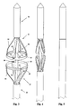
- Nachfolgend wird ein Ausführungsbeispiel der Erfindungen anhand der Zeichnungen näher beschrieben. Es zeigen:
- Fig. 1 und 2
- in vereinfachter Darstellung die konstruktiven Funktionsteile eines erfindungsgemäßen Instrumentes,
- Fig. 3 bis 5
- in perspektivischer Darstellung den Einziehvorgang der Schneidringhälften bei einem Instrument gemäß den
Figuren 1 und 2 . - Der grundsätzliche Aufbau eines erfindungsgemäßen Instrumentes ist am besten aus der
Fig. 3 in Verbindung mit denFiguren 1 + 2 ersichtlich. - Zu erkennen ist der zentrale Führungsstab 10, der sich in den Darstellungen nach unten bis zu einem instrumentalen Handgriff fortsetzt, der in den Figuren nicht mit dargestellt ist, da er von üblicher Konstruktion und Gestaltung sein kann. In und an einem solchen Handgriff sind diverse Stellantriebe und Arretierungsvorrichtungen vorhanden, mittels der die Funktionsteile des Instrumentes, wie sie nachfolgend benannt sind, jeweils einzeln gesteuert (verstellt) und/oder arretiert werden können. Das geschieht üblicherweise mittels zum Führungsstab parallel laufender Steuerstangen und/oder koaxial ineinander geführten Steuerhülsen.
- Koaxial um den Führungsstab 10 sind zwei spiegelbildlich zueinander ausgebildete Werkzeughälften 11 und 12 vorhanden, jeweils bestehend aus einem Schneidring 13 und 14 mit ihren jeweils vier Laschenverbindungen 15 bis 18 und 19 bis 22, die jeweils mit ihren Fußenden am Führungsstab 10 gelagert sind. Die Schneidringe sind aus einem elastisch verformbaren Flachbandmaterial gefertigt und auf eine geometrisch exakte Kreisform vorgeformt. Die Laschenverbindungen sind in Längsrichtung des Führungsstabes zug- und druckfest, aber in radialer Richtung zum Führungsstab beim Auftreten entsprechender radialer Kraftkomponenten elastisch verformbar.
- Die bei jeder Werkzeughälfte einander gegenüberliegenden Laschenverbindungen 15 und 17 (siehe obere Werkzeughälfte) bzw. 19 und 21 (siehe untere Werkzeughälfte) fixieren kopfseitig die Klappachsen 23 und 24 bzw. 25 und 26. Bei der oberen Werkzeughälfte sind die Fußenden der Laschenverbindungen 15 und 17 in einem Gleitstein 27 und die Fußenden der Laschenverbindungen 16 und 18 an einem Lagerstein 28 befestigt (siehe
Fig. 2 ). Bei der unteren Werkzeughälfte gilt das entsprechend für den Gleitstein 29 und den Lagerstein 30 (sieheFig. 2 ). - Die jeweiligen Lagersteine 28 und 30 sind in ihrer axialen Position ortsfest gehalten, wohingegen die Gleitsteine 27 und 29 axial verschiebbar und arretierbar am Führungsstab 10 gelagert sind.
- Die obere Werkzeughälfte 11 wird durch eine Rotation des Führungsstabes 10 auf die untere Werkzeughälfte 12 zubewegt, so daß mittels eines Dreh-Stanz-Vorgangs eine defekte Herzklappe, die in der Ebene 31 zwischen den beiden Werkzeughälften positioniert ist (siehe
Fig. 1 ), und durch die unter Bildung eines engen Scherspaltes ineinandergreifenden Schneidringe 13 und 14 ausgeschnitten wird. Die Funktionsbauteile zum Rotieren der oberen Werkzeughälfte 10 sind aus Gründen der besseren Übersichtlichkeit in den Figuren nicht mit dargestellt. Sie sind von üblicher Bauart. - Zum Einklappen der Schneidringe 13 und 14 bzw. deren jeweiligen halbkreisförmigen Schneidringhälften, die miteinander mittels der Klappachsen 23 + 24 bzw. 25 + 26 verbunden sind, werden die den jeweiligen Klappachsen zugeordneten Laschenverbindungen 15 + 17 bzw. 19 + 21 mittels ihrer fußseitigen Gleitsteine 27 bzw. 29 in axialer Längsrichtung des Führungsstabes verschoben, und zwar bei der oberen Werkzeughälfte darstellungsgemäß nach oben und bei der unteren Werkzeughälfte darstellungsgemäß nach unten. Diese Laschenverbindungen nehmen dann die Positionen ein, wie sie aus
Fig. 4 ersichtlich sind. - Die anderen Laschenverbindungen 18 + 16 der oberen Werkzeughälfte und 20 + 22 der unteren Werkzeughälfte halten ihre jeweiligen axialen Positionen, so daß sich die jeweiligen Schneidringhälften in die Halbform eines Ovals (oder ähnlich) verformen, wie dies in
Fig. 4 gezeigt ist. - Im Ergebnis wird sodann ein eingezogener Zustand der Laschenverbindungen und der Schneidringhälften erreicht, bei dem die beiden Berührungsschutzhülsen 32 und 33 jeweils gegenläufig und problemlos auf die eingefahrenen bzw. eingezogenen Werkzeughälften aufgeschoben werden können. Den mittels der Berührungsschutzhülsen vollständig geschlossenen Zustand des erfindungsgemäßen Instrumentes zeigt
Fig. 5 .
Claims (5)
- Instrument zum operativen Entfernen einer defekten Herzklappe,- das Instrument besitzt zwei an oder auf einem Führungsstab koaxial und in einem Abstand zueinander angeordnete Werkzeughälften, die mittels des Führungsstabes relativ zueinander axial verschiebbar sind derart, daß ihre gegeneinander gerichteten Werkzeugschneiden eine zwischen den Werkzeughälften positionierte defekte Herzklappe ausschneiden,- zum operativen Einführen des Instrumentes in das Operationsgebiet sind die Schneiden der Werkzeughälften radial einziehbar, d.h. deren radialer Abstand von der Werkzeugachse wird verkleinert, und es ist eine im Durchmesser enger an den Führungsstab angepaßte Berührungsschutzhülse auf die Werkzeughälften mit den radial eingezogenen Schneiden axial aufschiebbar, so daß das vorlaufende (distale) Ende des Instrumentes mit der im Durchmesser enger an den Führungsstab angepaßten Berührungsschutzhülse ein stückweit durch die defekte Herzklappe hindurchzuschieben ist bis in eine Position, in der sich die eine Werkzeughälfte auf der einen Seite der defekten Herzklappe und die andere Werkzeughälfte auf der anderen Seite der defekten Herzklappe befindet,- in dieser Position wird die Berührungsschutzhülse axial von den Werkzeughälften abgezogen und die Schneiden der Werkzeughälften sind radial ausfahrbar, d. h. deren radialer Abstand von der Werkzeugachse wird vergrößert bis auf einen Durchmesser, der dem Durchmesser der auszuschneidenden defekten Herzklappe und dem Durchmesser der nachfolgend operativ einzusetzenden neuen Herzklappe entspricht,dadurch gekennzeichnet,- daß die Schneiden der Werkzeughälften jeweils aus zwei halbkreisförmigen Schneidringhälften gebildet sind, die endseitig miteinander über je eine einachsige Gelenkverbindung (= Klappachsen 23,24,25,26) zu einem kreisrunden Schneidring (13,14) verbunden sind, wobei jede Schneidringhälfte aus einem elastisch verformbaren flachen Materialband gefertigt ist (vorzugsweise aus super-elastischem Nitinol) und jeweils im Hochkantformat auf den im radial ausgefahrenen Zustand geforderten Halbkreis-Durchmesser maßhaltig vorgeformt ist,- daß die Klappachsen der Schneidringhälften senkrecht zu der Achse des Führungsstabes (10) ausgerichtet sind und jeweils mittels des Kopfendes einer elastisch verformbaren, aber zug- und druckfesten Laschenverbindung ( 15, 17, 19, 21) fixiert sind, die sich in Längsrichtung des Führungsstabes erstrecken und die jeweils mit ihren Fußenden am Führungsstab gelagert sind,- und daß jede Schneidringhälfte mittels einer weiteren elastisch verformbaren, zug- und druckfesten, sich in Längsrichtung des Führungsstabes erstreckenden und mit ihrem Fußende am Führungsstab gelagerten Laschenverbindung (16,18,20,22) gehalten ist, deren Kopfende in der Mitte des Halbkreises an der im ausgefahrenen Zustand halbkreiförmigen Schneidringhälfte angelenkt ist, wobei diese Anlenkung und/oder die elastisch verformbare Laschenverbindung der Schneidringhälfte erlaubt, eine Schwenkbewegung von nahezu 90° um eine quer zur Laschenverbindung verlaufende Achse auszuführen.
- Instrument nach Anspruch 1,
dadurch gekennzeichnet,- daß die Laschenverbindungen (16, 18, 20, 22), deren Kopfenden an der Mitte der Schneidringhälften angelenkt sind, mit ihren jeweiligen Fußenden am Führungsstab (10) ortsfest gelagert sind,- und daß die Laschenverbindungen (15,17, 19,21), deren Kopfenden die Kippachsen fixieren, mit ihren jeweiligen Fußenden an oder auf dem Führungsstab (10) axial verschiebbar und arretierbar gelagert sind. - Instrument nach Anspruch 1,
dadurch gekennzeichnet,- daß das Instrument für jede Werkzeughälfte eine eigene Berührungsschutzhülse (32,33) besitzt, die auf den Laschenverbindungen, die der jeweiligen Werkzeughälfte zugeordnet sind, aufgelagert ist und die auf diesen Laschenverbindungen axial und gegenläufig zu der Berührungsschutzhülse der anderen Werkzeughälfte verschiebbar ist. - Instrument nach Anspruch 1,
dadurch gekennzeichnet,- daß der Durchmesser des Schneidringes (14) der einen Werkzeughälfte (12) geringfügig größer ist als der Durchmesser des Schneidringes (13) der anderen Werkzeughälfte (11) derart, daß beide Schneidringe beim Ausschneiden der zwischen ihnen positionierten defekten Herzklappe unter Bildung eines engen Scherspaltes ineinandergreifen. - Instrument nach Anspruch 1,
dadurch gekennzeichnet,- daß die Werkzeughälften mit ihren Schneidringen relativ zueinander rotierbar sind derart, daß die defekte Herzklappe durch einen Dreh-Stanz-Vorgang ausgeschnitten wird.
Applications Claiming Priority (1)
| Application Number | Priority Date | Filing Date | Title |
|---|---|---|---|
| DE102007005900A DE102007005900A1 (de) | 2007-02-01 | 2007-02-01 | Instrument zum operativen Entfernen einer defekten Herzklappe |
Publications (2)
| Publication Number | Publication Date |
|---|---|
| EP1952772A1 true EP1952772A1 (de) | 2008-08-06 |
| EP1952772B1 EP1952772B1 (de) | 2010-08-18 |
Family
ID=39365788
Family Applications (1)
| Application Number | Title | Priority Date | Filing Date |
|---|---|---|---|
| EP08001034A Active EP1952772B1 (de) | 2007-02-01 | 2008-01-21 | Instrument zum operativen Entfernen einer defekten Herzklappe |
Country Status (4)
| Country | Link |
|---|---|
| US (1) | US8979878B2 (de) |
| EP (1) | EP1952772B1 (de) |
| AT (1) | ATE477754T1 (de) |
| DE (2) | DE102007005900A1 (de) |
Families Citing this family (49)
| Publication number | Priority date | Publication date | Assignee | Title |
|---|---|---|---|---|
| ITTO20040135A1 (it) | 2004-03-03 | 2004-06-03 | Sorin Biomedica Cardio Spa | Protesi valvolare cardiaca |
| ITTO20050074A1 (it) | 2005-02-10 | 2006-08-11 | Sorin Biomedica Cardio Srl | Protesi valvola cardiaca |
| CA2664557C (en) | 2006-11-07 | 2015-05-26 | Corvia Medical, Inc. | Devices and methods for the treatment of heart failure |
| US20110257723A1 (en) | 2006-11-07 | 2011-10-20 | Dc Devices, Inc. | Devices and methods for coronary sinus pressure relief |
| US10413284B2 (en) | 2006-11-07 | 2019-09-17 | Corvia Medical, Inc. | Atrial pressure regulation with control, sensing, monitoring and therapy delivery |
| US9232997B2 (en) | 2006-11-07 | 2016-01-12 | Corvia Medical, Inc. | Devices and methods for retrievable intra-atrial implants |
| US9848981B2 (en) | 2007-10-12 | 2017-12-26 | Mayo Foundation For Medical Education And Research | Expandable valve prosthesis with sealing mechanism |
| ATE554731T1 (de) | 2008-05-16 | 2012-05-15 | Sorin Biomedica Cardio Srl | Atraumatische prothetische herzklappenprothese |
| ES2551694T3 (es) | 2008-12-23 | 2015-11-23 | Sorin Group Italia S.R.L. | Válvula protésica expansible dotada de apéndices de anclaje |
| WO2010118064A1 (en) * | 2009-04-06 | 2010-10-14 | O'donnell Michael J | System and method for resecting a valve |
| EP2628465A1 (de) | 2009-04-27 | 2013-08-21 | Sorin Group Italia S.r.l. | Prothetische Gefässleitung |
| US8808369B2 (en) | 2009-10-05 | 2014-08-19 | Mayo Foundation For Medical Education And Research | Minimally invasive aortic valve replacement |
| WO2011093941A2 (en) | 2010-01-29 | 2011-08-04 | Dc Devices, Inc. | Devices and systems for treating heart failure |
| DE102010011773B4 (de) * | 2010-03-17 | 2015-10-01 | Christian-Albrechts-Universität Zu Kiel | Katheterbasierte Herzklappenablationsvorrichtung |
| US8579964B2 (en) | 2010-05-05 | 2013-11-12 | Neovasc Inc. | Transcatheter mitral valve prosthesis |
| IT1400327B1 (it) | 2010-05-21 | 2013-05-24 | Sorin Biomedica Cardio Srl | Dispositivo di supporto per protesi valvolari e corrispondente corredo. |
| JP2014512869A (ja) | 2011-02-10 | 2014-05-29 | ディーシー ディヴァイシーズ インコーポレイテッド | 心房内圧力軽減開口を形成させ維持する装置および方法 |
| US12303119B2 (en) | 2011-02-10 | 2025-05-20 | Corvia Medical, Inc. | Apparatus and methods to create and maintain an intra-atrial pressure relief opening |
| ES2641902T3 (es) | 2011-02-14 | 2017-11-14 | Sorin Group Italia S.R.L. | Dispositivo de anclaje sin sutura para prótesis valvulares cardiacas |
| EP2486894B1 (de) | 2011-02-14 | 2021-06-09 | Sorin Group Italia S.r.l. | Vorrichtung zur nahtlosen Verankerung von Herzklappenprothesen |
| US9308087B2 (en) | 2011-04-28 | 2016-04-12 | Neovasc Tiara Inc. | Sequentially deployed transcatheter mitral valve prosthesis |
| US9554897B2 (en) | 2011-04-28 | 2017-01-31 | Neovasc Tiara Inc. | Methods and apparatus for engaging a valve prosthesis with tissue |
| US8945177B2 (en) * | 2011-09-13 | 2015-02-03 | Abbott Cardiovascular Systems Inc. | Gripper pusher mechanism for tissue apposition systems |
| US20130158345A1 (en) * | 2011-12-19 | 2013-06-20 | Heshmat Majlessi | Veno-Merse / Harvester Device |
| US9205236B2 (en) | 2011-12-22 | 2015-12-08 | Corvia Medical, Inc. | Methods, systems, and devices for resizable intra-atrial shunts |
| EP2609893B1 (de) | 2011-12-29 | 2014-09-03 | Sorin Group Italia S.r.l. | Kit zur Implantation von prothetischen Gefäßleitungen |
| US9345573B2 (en) | 2012-05-30 | 2016-05-24 | Neovasc Tiara Inc. | Methods and apparatus for loading a prosthesis onto a delivery system |
| DE102012109459A1 (de) | 2012-10-04 | 2014-04-10 | Aesculap Ag | Weiteneinstellbares Schneidinstrument zur transapikalen Aortenklappenresektion |
| US9775636B2 (en) * | 2013-03-12 | 2017-10-03 | Corvia Medical, Inc. | Devices, systems, and methods for treating heart failure |
| GB2512386B (en) * | 2013-03-28 | 2017-02-01 | Cook Medical Technologies Llc | Medical device retrieval apparatus |
| US9572665B2 (en) | 2013-04-04 | 2017-02-21 | Neovasc Tiara Inc. | Methods and apparatus for delivering a prosthetic valve to a beating heart |
| US10675450B2 (en) | 2014-03-12 | 2020-06-09 | Corvia Medical, Inc. | Devices and methods for treating heart failure |
| JP6799526B2 (ja) | 2014-07-23 | 2020-12-16 | コルヴィア メディカル インコーポレイテッド | 心不全の治療のための装置及び方法 |
| DE202016008737U1 (de) | 2015-12-15 | 2019-04-05 | Neovasc Tiara Inc. | Transseptales Zuführsystem |
| CN108882981B (zh) | 2016-01-29 | 2021-08-10 | 内奥瓦斯克迪亚拉公司 | 用于防止流出阻塞的假体瓣膜 |
| US20180098777A1 (en) * | 2016-10-11 | 2018-04-12 | Shlomo Gabbay | Devices and Methods for Improving Transcatheter Aortic Valve Implantation |
| CN109996581B (zh) | 2016-11-21 | 2021-10-15 | 内奥瓦斯克迪亚拉公司 | 用于快速收回经导管心脏瓣膜递送系统的方法和系统 |
| GB2563420B (en) * | 2017-06-15 | 2019-09-18 | Strait Access Tech Holdings Pty Ltd | Valve leaflet connecting device |
| CA3073834A1 (en) | 2017-08-25 | 2019-02-28 | Neovasc Tiara Inc. | Sequentially deployed transcatheter mitral valve prosthesis |
| US11931257B2 (en) | 2018-03-27 | 2024-03-19 | Medtronic, Inc. | Devices and methods for aortic valve preparation prior to transcatheter prosthetic valve procedures |
| CN108742922B (zh) * | 2018-04-10 | 2023-04-28 | 中国人民解放军总医院 | 一种口腔手术时使用的组织牵开装置 |
| US12318289B2 (en) | 2018-05-23 | 2025-06-03 | Corcym S.R.L. | Device for the in-situ delivery of heart valve prosthesis |
| WO2019224577A1 (en) | 2018-05-23 | 2019-11-28 | Sorin Group Italia S.R.L. | A cardiac valve prosthesis |
| WO2020093172A1 (en) | 2018-11-08 | 2020-05-14 | Neovasc Tiara Inc. | Ventricular deployment of a transcatheter mitral valve prosthesis |
| WO2020185597A1 (en) | 2019-03-08 | 2020-09-17 | Neovasc Tiara Inc. | Retrievable prosthesis delivery system |
| US11602429B2 (en) | 2019-04-01 | 2023-03-14 | Neovasc Tiara Inc. | Controllably deployable prosthetic valve |
| EP3952792A4 (de) | 2019-04-10 | 2023-01-04 | Neovasc Tiara Inc. | Herzklappenprothese mit natürlichem blutfluss |
| EP3972673B1 (de) | 2019-05-20 | 2026-01-28 | Neovasc Tiara Inc. | Einführungsvorrichtung mit hämostasemechanismus |
| CN114144144B (zh) | 2019-06-20 | 2026-01-13 | 内奥瓦斯克迪亚拉公司 | 低轮廓假体二尖瓣 |
Citations (6)
| Publication number | Priority date | Publication date | Assignee | Title |
|---|---|---|---|---|
| US5924424A (en) | 1993-02-22 | 1999-07-20 | Heartport, Inc. | Method and apparatus for thoracoscopic intracardiac procedures |
| WO2004089250A1 (en) * | 2003-03-30 | 2004-10-21 | Fidel Realyvasquez | Apparatus and methods for valve repair |
| US6830584B1 (en) | 1999-11-17 | 2004-12-14 | Jacques Seguin | Device for replacing a cardiac valve by percutaneous route |
| US20050075659A1 (en) | 2003-03-30 | 2005-04-07 | Fidel Realyvasquez | Apparatus and methods for minimally invasive valve surgery |
| US20050131438A1 (en) | 2001-06-29 | 2005-06-16 | Cohn William E. | Method and apparatus for resecting and replacing an aortic valve |
| DE60017169T2 (de) | 1999-04-30 | 2006-03-30 | Nokia Corp. | Antennenanordnung mit aktivem element und reflektor |
Family Cites Families (7)
| Publication number | Priority date | Publication date | Assignee | Title |
|---|---|---|---|---|
| US7014647B2 (en) * | 1999-05-07 | 2006-03-21 | Salviac Limited | Support frame for an embolic protection device |
| DE10049865B8 (de) * | 2000-10-09 | 2008-10-30 | Universitätsklinikum Freiburg | Vorrichtung zur Entfernung einer Aortenklappe am menschlichen Herz im Wege eines minimal invasiven chirurgischen Eingriffs |
| US7201761B2 (en) * | 2001-06-29 | 2007-04-10 | Medtronic, Inc. | Method and apparatus for resecting and replacing an aortic valve |
| US7192434B2 (en) * | 2002-03-08 | 2007-03-20 | Ev3 Inc. | Vascular protection devices and methods of use |
| US7041132B2 (en) * | 2002-08-16 | 2006-05-09 | 3F Therapeutics, Inc, | Percutaneously delivered heart valve and delivery means thereof |
| WO2004043273A2 (en) * | 2002-11-13 | 2004-05-27 | Rosengart Todd K | Apparatus and method for cutting a heart valve |
| US7815676B2 (en) * | 2006-07-07 | 2010-10-19 | The Cleveland Clinic Foundation | Apparatus and method for assisting in the removal of a cardiac valve |
-
2007
- 2007-02-01 DE DE102007005900A patent/DE102007005900A1/de not_active Withdrawn
-
2008
- 2008-01-21 DE DE502008001132T patent/DE502008001132D1/de active Active
- 2008-01-21 EP EP08001034A patent/EP1952772B1/de active Active
- 2008-01-21 AT AT08001034T patent/ATE477754T1/de active
- 2008-01-29 US US12/021,396 patent/US8979878B2/en active Active
Patent Citations (7)
| Publication number | Priority date | Publication date | Assignee | Title |
|---|---|---|---|---|
| US5924424A (en) | 1993-02-22 | 1999-07-20 | Heartport, Inc. | Method and apparatus for thoracoscopic intracardiac procedures |
| DE60017169T2 (de) | 1999-04-30 | 2006-03-30 | Nokia Corp. | Antennenanordnung mit aktivem element und reflektor |
| US6830584B1 (en) | 1999-11-17 | 2004-12-14 | Jacques Seguin | Device for replacing a cardiac valve by percutaneous route |
| DE60017189T2 (de) | 1999-11-17 | 2005-09-22 | Jacques Seguin | Perkutane vorrichtung zum ersetzen einer herzklappe |
| US20050131438A1 (en) | 2001-06-29 | 2005-06-16 | Cohn William E. | Method and apparatus for resecting and replacing an aortic valve |
| WO2004089250A1 (en) * | 2003-03-30 | 2004-10-21 | Fidel Realyvasquez | Apparatus and methods for valve repair |
| US20050075659A1 (en) | 2003-03-30 | 2005-04-07 | Fidel Realyvasquez | Apparatus and methods for minimally invasive valve surgery |
Also Published As
| Publication number | Publication date |
|---|---|
| ATE477754T1 (de) | 2010-09-15 |
| DE502008001132D1 (de) | 2010-09-30 |
| US20080188880A1 (en) | 2008-08-07 |
| EP1952772B1 (de) | 2010-08-18 |
| DE102007005900A1 (de) | 2008-08-07 |
| US8979878B2 (en) | 2015-03-17 |
Similar Documents
| Publication | Publication Date | Title |
|---|---|---|
| EP1952772B1 (de) | Instrument zum operativen Entfernen einer defekten Herzklappe | |
| DE69323012T2 (de) | Endoskopisches chirurgisches Gelenkwerkzeug | |
| DE102011009482B4 (de) | Sicherheitskanüle | |
| DE3603344A1 (de) | Vorrichtung zum zertruemmern von steinen, insbesondere von nieren- und gallensteinen oder dgl. | |
| DE19908721A1 (de) | Instrument zum Schneiden von biologischem und insbesondere menschlichem Gewebe | |
| DE8903650U1 (de) | Chirurgisches Instrument zur Herstellung von Kompressions-Anastomose | |
| DE4114311A1 (de) | Extraktor | |
| DE102011053638A1 (de) | Marknagel | |
| EP2775941B1 (de) | Anastomosegerät mit kollabierbarem distalem kopfelement | |
| EP2769682A1 (de) | Endoskopisches Instrument sowie Schaft für ein endoskopisches Instrument | |
| EP2265186B1 (de) | Medizinischer aufnahmebeutel und verfahren zu dessen herstellung | |
| EP0696901B1 (de) | Endoskopische schneidvorrichtung | |
| WO2009007057A1 (de) | Stent mit einer rohrförmigen glitterstruktur und verfahren zum herstellen eines derartigen stents | |
| WO2011079897A1 (de) | Steuerung eines rohrförmigen schafts eines chirurgischen instruments | |
| EP2340759A1 (de) | Endoskopisches Instrument | |
| EP0879018B1 (de) | Vorrichtung zum anheben der bauchdecke für die durchführung laparoskopischer untersuchungen | |
| DE112014001237B4 (de) | Behandlungsinstrument für endoskopische Operation | |
| DE19629537A1 (de) | Trokarhülse | |
| DE10027186C2 (de) | Vorrichtung zum Verschliessen einer Öffnung in einer Gewebeschicht | |
| DE9105399U1 (de) | Extraktor | |
| EP2653122B1 (de) | Werkzeug für ein medizinisches Instrument | |
| DE10145107B4 (de) | Füllstab für Endoskope | |
| DE102009037045A1 (de) | Rohrförmiger Schaft eines chirurgischen Instruments | |
| DE20016971U1 (de) | Vorrichtung zur Schaffung eines perkutanen Zugangs | |
| DE3408243A1 (de) | Urethrotom fuer die harnroehrenerweiterung |
Legal Events
| Date | Code | Title | Description |
|---|---|---|---|
| PUAI | Public reference made under article 153(3) epc to a published international application that has entered the european phase |
Free format text: ORIGINAL CODE: 0009012 |
|
| AK | Designated contracting states |
Kind code of ref document: A1 Designated state(s): AT BE BG CH CY CZ DE DK EE ES FI FR GB GR HR HU IE IS IT LI LT LU LV MC MT NL NO PL PT RO SE SI SK TR |
|
| AX | Request for extension of the european patent |
Extension state: AL BA MK RS |
|
| 17P | Request for examination filed |
Effective date: 20090203 |
|
| 17Q | First examination report despatched |
Effective date: 20090306 |
|
| AKX | Designation fees paid |
Designated state(s): AT BE BG CH CY CZ DE DK EE ES FI FR GB GR HR HU IE IS IT LI LT LU LV MC MT NL NO PL PT RO SE SI SK TR |
|
| GRAP | Despatch of communication of intention to grant a patent |
Free format text: ORIGINAL CODE: EPIDOSNIGR1 |
|
| GRAS | Grant fee paid |
Free format text: ORIGINAL CODE: EPIDOSNIGR3 |
|
| GRAA | (expected) grant |
Free format text: ORIGINAL CODE: 0009210 |
|
| AK | Designated contracting states |
Kind code of ref document: B1 Designated state(s): AT BE BG CH CY CZ DE DK EE ES FI FR GB GR HR HU IE IS IT LI LT LU LV MC MT NL NO PL PT RO SE SI SK TR |
|
| REG | Reference to a national code |
Ref country code: GB Ref legal event code: FG4D Free format text: NOT ENGLISH |
|
| REG | Reference to a national code |
Ref country code: CH Ref legal event code: EP |
|
| REG | Reference to a national code |
Ref country code: IE Ref legal event code: FG4D Free format text: LANGUAGE OF EP DOCUMENT: GERMAN |
|
| REF | Corresponds to: |
Ref document number: 502008001132 Country of ref document: DE Date of ref document: 20100930 Kind code of ref document: P |
|
| REG | Reference to a national code |
Ref country code: DE Ref legal event code: R096 Ref document number: 502008001132 Country of ref document: DE Effective date: 20100930 |
|
| REG | Reference to a national code |
Ref country code: NL Ref legal event code: VDEP Effective date: 20100818 |
|
| LTIE | Lt: invalidation of european patent or patent extension |
Effective date: 20100818 |
|
| PG25 | Lapsed in a contracting state [announced via postgrant information from national office to epo] |
Ref country code: FI Free format text: LAPSE BECAUSE OF FAILURE TO SUBMIT A TRANSLATION OF THE DESCRIPTION OR TO PAY THE FEE WITHIN THE PRESCRIBED TIME-LIMIT Effective date: 20100818 Ref country code: NO Free format text: LAPSE BECAUSE OF FAILURE TO SUBMIT A TRANSLATION OF THE DESCRIPTION OR TO PAY THE FEE WITHIN THE PRESCRIBED TIME-LIMIT Effective date: 20101118 Ref country code: LT Free format text: LAPSE BECAUSE OF FAILURE TO SUBMIT A TRANSLATION OF THE DESCRIPTION OR TO PAY THE FEE WITHIN THE PRESCRIBED TIME-LIMIT Effective date: 20100818 |
|
| PG25 | Lapsed in a contracting state [announced via postgrant information from national office to epo] |
Ref country code: CY Free format text: LAPSE BECAUSE OF FAILURE TO SUBMIT A TRANSLATION OF THE DESCRIPTION OR TO PAY THE FEE WITHIN THE PRESCRIBED TIME-LIMIT Effective date: 20100818 Ref country code: BG Free format text: LAPSE BECAUSE OF FAILURE TO SUBMIT A TRANSLATION OF THE DESCRIPTION OR TO PAY THE FEE WITHIN THE PRESCRIBED TIME-LIMIT Effective date: 20101118 Ref country code: SI Free format text: LAPSE BECAUSE OF FAILURE TO SUBMIT A TRANSLATION OF THE DESCRIPTION OR TO PAY THE FEE WITHIN THE PRESCRIBED TIME-LIMIT Effective date: 20100818 Ref country code: HR Free format text: LAPSE BECAUSE OF FAILURE TO SUBMIT A TRANSLATION OF THE DESCRIPTION OR TO PAY THE FEE WITHIN THE PRESCRIBED TIME-LIMIT Effective date: 20100818 Ref country code: IS Free format text: LAPSE BECAUSE OF FAILURE TO SUBMIT A TRANSLATION OF THE DESCRIPTION OR TO PAY THE FEE WITHIN THE PRESCRIBED TIME-LIMIT Effective date: 20101218 Ref country code: PL Free format text: LAPSE BECAUSE OF FAILURE TO SUBMIT A TRANSLATION OF THE DESCRIPTION OR TO PAY THE FEE WITHIN THE PRESCRIBED TIME-LIMIT Effective date: 20100818 |
|
| REG | Reference to a national code |
Ref country code: IE Ref legal event code: FD4D |
|
| PG25 | Lapsed in a contracting state [announced via postgrant information from national office to epo] |
Ref country code: LV Free format text: LAPSE BECAUSE OF FAILURE TO SUBMIT A TRANSLATION OF THE DESCRIPTION OR TO PAY THE FEE WITHIN THE PRESCRIBED TIME-LIMIT Effective date: 20100818 Ref country code: NL Free format text: LAPSE BECAUSE OF FAILURE TO SUBMIT A TRANSLATION OF THE DESCRIPTION OR TO PAY THE FEE WITHIN THE PRESCRIBED TIME-LIMIT Effective date: 20100818 Ref country code: GR Free format text: LAPSE BECAUSE OF FAILURE TO SUBMIT A TRANSLATION OF THE DESCRIPTION OR TO PAY THE FEE WITHIN THE PRESCRIBED TIME-LIMIT Effective date: 20101119 Ref country code: SE Free format text: LAPSE BECAUSE OF FAILURE TO SUBMIT A TRANSLATION OF THE DESCRIPTION OR TO PAY THE FEE WITHIN THE PRESCRIBED TIME-LIMIT Effective date: 20100818 |
|
| PG25 | Lapsed in a contracting state [announced via postgrant information from national office to epo] |
Ref country code: DK Free format text: LAPSE BECAUSE OF FAILURE TO SUBMIT A TRANSLATION OF THE DESCRIPTION OR TO PAY THE FEE WITHIN THE PRESCRIBED TIME-LIMIT Effective date: 20100818 Ref country code: IE Free format text: LAPSE BECAUSE OF FAILURE TO SUBMIT A TRANSLATION OF THE DESCRIPTION OR TO PAY THE FEE WITHIN THE PRESCRIBED TIME-LIMIT Effective date: 20100818 |
|
| PG25 | Lapsed in a contracting state [announced via postgrant information from national office to epo] |
Ref country code: EE Free format text: LAPSE BECAUSE OF FAILURE TO SUBMIT A TRANSLATION OF THE DESCRIPTION OR TO PAY THE FEE WITHIN THE PRESCRIBED TIME-LIMIT Effective date: 20100818 Ref country code: IT Free format text: LAPSE BECAUSE OF FAILURE TO SUBMIT A TRANSLATION OF THE DESCRIPTION OR TO PAY THE FEE WITHIN THE PRESCRIBED TIME-LIMIT Effective date: 20100818 Ref country code: CZ Free format text: LAPSE BECAUSE OF FAILURE TO SUBMIT A TRANSLATION OF THE DESCRIPTION OR TO PAY THE FEE WITHIN THE PRESCRIBED TIME-LIMIT Effective date: 20100818 Ref country code: RO Free format text: LAPSE BECAUSE OF FAILURE TO SUBMIT A TRANSLATION OF THE DESCRIPTION OR TO PAY THE FEE WITHIN THE PRESCRIBED TIME-LIMIT Effective date: 20100818 Ref country code: SK Free format text: LAPSE BECAUSE OF FAILURE TO SUBMIT A TRANSLATION OF THE DESCRIPTION OR TO PAY THE FEE WITHIN THE PRESCRIBED TIME-LIMIT Effective date: 20100818 |
|
| PLBE | No opposition filed within time limit |
Free format text: ORIGINAL CODE: 0009261 |
|
| STAA | Information on the status of an ep patent application or granted ep patent |
Free format text: STATUS: NO OPPOSITION FILED WITHIN TIME LIMIT |
|
| PG25 | Lapsed in a contracting state [announced via postgrant information from national office to epo] |
Ref country code: ES Free format text: LAPSE BECAUSE OF FAILURE TO SUBMIT A TRANSLATION OF THE DESCRIPTION OR TO PAY THE FEE WITHIN THE PRESCRIBED TIME-LIMIT Effective date: 20101129 |
|
| 26N | No opposition filed |
Effective date: 20110519 |
|
| BERE | Be: lapsed |
Owner name: ENDOSMART G.- FUR INNOVATIVE MEDIZINTECHNIK MBH Effective date: 20110131 |
|
| PG25 | Lapsed in a contracting state [announced via postgrant information from national office to epo] |
Ref country code: MC Free format text: LAPSE BECAUSE OF NON-PAYMENT OF DUE FEES Effective date: 20110131 |
|
| REG | Reference to a national code |
Ref country code: DE Ref legal event code: R097 Ref document number: 502008001132 Country of ref document: DE Effective date: 20110519 |
|
| PG25 | Lapsed in a contracting state [announced via postgrant information from national office to epo] |
Ref country code: BE Free format text: LAPSE BECAUSE OF NON-PAYMENT OF DUE FEES Effective date: 20110131 |
|
| PG25 | Lapsed in a contracting state [announced via postgrant information from national office to epo] |
Ref country code: MT Free format text: LAPSE BECAUSE OF FAILURE TO SUBMIT A TRANSLATION OF THE DESCRIPTION OR TO PAY THE FEE WITHIN THE PRESCRIBED TIME-LIMIT Effective date: 20100818 |
|
| REG | Reference to a national code |
Ref country code: CH Ref legal event code: PL |
|
| GBPC | Gb: european patent ceased through non-payment of renewal fee |
Effective date: 20120121 |
|
| PG25 | Lapsed in a contracting state [announced via postgrant information from national office to epo] |
Ref country code: CH Free format text: LAPSE BECAUSE OF NON-PAYMENT OF DUE FEES Effective date: 20120131 Ref country code: GB Free format text: LAPSE BECAUSE OF NON-PAYMENT OF DUE FEES Effective date: 20120121 Ref country code: LI Free format text: LAPSE BECAUSE OF NON-PAYMENT OF DUE FEES Effective date: 20120131 |
|
| PG25 | Lapsed in a contracting state [announced via postgrant information from national office to epo] |
Ref country code: LU Free format text: LAPSE BECAUSE OF NON-PAYMENT OF DUE FEES Effective date: 20110121 |
|
| PG25 | Lapsed in a contracting state [announced via postgrant information from national office to epo] |
Ref country code: PT Free format text: LAPSE BECAUSE OF NON-PAYMENT OF DUE FEES Effective date: 20100818 |
|
| PG25 | Lapsed in a contracting state [announced via postgrant information from national office to epo] |
Ref country code: TR Free format text: LAPSE BECAUSE OF FAILURE TO SUBMIT A TRANSLATION OF THE DESCRIPTION OR TO PAY THE FEE WITHIN THE PRESCRIBED TIME-LIMIT Effective date: 20100818 |
|
| PG25 | Lapsed in a contracting state [announced via postgrant information from national office to epo] |
Ref country code: HU Free format text: LAPSE BECAUSE OF FAILURE TO SUBMIT A TRANSLATION OF THE DESCRIPTION OR TO PAY THE FEE WITHIN THE PRESCRIBED TIME-LIMIT Effective date: 20100818 |
|
| REG | Reference to a national code |
Ref country code: DE Ref legal event code: R082 Ref document number: 502008001132 Country of ref document: DE Representative=s name: VOSSIUS & PARTNER PATENTANWAELTE RECHTSANWAELT, DE Ref country code: DE Ref legal event code: R082 Ref document number: 502008001132 Country of ref document: DE Representative=s name: VOSSIUS & PARTNER, DE Ref country code: DE Ref legal event code: R082 Ref document number: 502008001132 Country of ref document: DE Representative=s name: WSL PATENTANWAELTE PARTNERSCHAFT MBB, DE |
|
| REG | Reference to a national code |
Ref country code: AT Ref legal event code: MM01 Ref document number: 477754 Country of ref document: AT Kind code of ref document: T Effective date: 20130121 |
|
| PG25 | Lapsed in a contracting state [announced via postgrant information from national office to epo] |
Ref country code: AT Free format text: LAPSE BECAUSE OF NON-PAYMENT OF DUE FEES Effective date: 20130121 |
|
| REG | Reference to a national code |
Ref country code: FR Ref legal event code: PLFP Year of fee payment: 9 |
|
| REG | Reference to a national code |
Ref country code: FR Ref legal event code: PLFP Year of fee payment: 10 |
|
| REG | Reference to a national code |
Ref country code: FR Ref legal event code: PLFP Year of fee payment: 11 |
|
| P01 | Opt-out of the competence of the unified patent court (upc) registered |
Effective date: 20230525 |
|
| REG | Reference to a national code |
Ref country code: DE Ref legal event code: R081 Ref document number: 502008001132 Country of ref document: DE Owner name: ENDOSMART GESELLSCHAFT FUER MEDIZINTECHNIK M.B, DE Free format text: FORMER OWNER: ENDOSMART GESELLSCHAFT FUER INNOVATIVE MEDIZINTECHNIK MBH, 76297 STUTENSEE, DE Ref country code: DE Ref legal event code: R082 Ref document number: 502008001132 Country of ref document: DE Representative=s name: WSL PATENTANWAELTE PARTNERSCHAFT MBB, DE Ref country code: DE Ref legal event code: R081 Ref document number: 502008001132 Country of ref document: DE Owner name: ALLEIMA KARLSRUHE GMBH, DE Free format text: FORMER OWNER: ENDOSMART GESELLSCHAFT FUER INNOVATIVE MEDIZINTECHNIK MBH, 76297 STUTENSEE, DE |
|
| REG | Reference to a national code |
Ref country code: DE Ref legal event code: R081 Ref document number: 502008001132 Country of ref document: DE Owner name: ALLEIMA KARLSRUHE GMBH, DE Free format text: FORMER OWNER: ENDOSMART GESELLSCHAFT FUER MEDIZINTECHNIK M.B.H., 76297 STUTENSEE, DE |
|
| PGFP | Annual fee paid to national office [announced via postgrant information from national office to epo] |
Ref country code: FR Payment date: 20241223 Year of fee payment: 18 |
|
| PGFP | Annual fee paid to national office [announced via postgrant information from national office to epo] |
Ref country code: DE Payment date: 20241203 Year of fee payment: 18 |