EP1952722A1 - Seat structure and vehicle - Google Patents
Seat structure and vehicle Download PDFInfo
- Publication number
- EP1952722A1 EP1952722A1 EP06832610A EP06832610A EP1952722A1 EP 1952722 A1 EP1952722 A1 EP 1952722A1 EP 06832610 A EP06832610 A EP 06832610A EP 06832610 A EP06832610 A EP 06832610A EP 1952722 A1 EP1952722 A1 EP 1952722A1
- Authority
- EP
- European Patent Office
- Prior art keywords
- cushion
- seat
- link
- main frame
- frame
- Prior art date
- Legal status (The legal status is an assumption and is not a legal conclusion. Google has not performed a legal analysis and makes no representation as to the accuracy of the status listed.)
- Granted
Links
Images





































Classifications
-
- B—PERFORMING OPERATIONS; TRANSPORTING
- B60—VEHICLES IN GENERAL
- B60N—SEATS SPECIALLY ADAPTED FOR VEHICLES; VEHICLE PASSENGER ACCOMMODATION NOT OTHERWISE PROVIDED FOR
- B60N2/00—Seats specially adapted for vehicles; Arrangement or mounting of seats in vehicles
- B60N2/90—Details or parts not otherwise provided for
- B60N2/986—Side-rests
- B60N2/99—Side-rests adjustable
-
- B—PERFORMING OPERATIONS; TRANSPORTING
- B60—VEHICLES IN GENERAL
- B60N—SEATS SPECIALLY ADAPTED FOR VEHICLES; VEHICLE PASSENGER ACCOMMODATION NOT OTHERWISE PROVIDED FOR
- B60N2/00—Seats specially adapted for vehicles; Arrangement or mounting of seats in vehicles
- B60N2/24—Seats specially adapted for vehicles; Arrangement or mounting of seats in vehicles for particular purposes or particular vehicles
- B60N2/30—Non-dismountable or dismountable seats storable in a non-use position, e.g. foldable spare seats
- B60N2/3002—Non-dismountable or dismountable seats storable in a non-use position, e.g. foldable spare seats back-rest movements
- B60N2/3004—Non-dismountable or dismountable seats storable in a non-use position, e.g. foldable spare seats back-rest movements by rotation only
- B60N2/3009—Non-dismountable or dismountable seats storable in a non-use position, e.g. foldable spare seats back-rest movements by rotation only about transversal axis
- B60N2/3011—Non-dismountable or dismountable seats storable in a non-use position, e.g. foldable spare seats back-rest movements by rotation only about transversal axis the back-rest being hinged on the cushion, e.g. "portefeuille movement"
-
- B—PERFORMING OPERATIONS; TRANSPORTING
- B60—VEHICLES IN GENERAL
- B60N—SEATS SPECIALLY ADAPTED FOR VEHICLES; VEHICLE PASSENGER ACCOMMODATION NOT OTHERWISE PROVIDED FOR
- B60N2/00—Seats specially adapted for vehicles; Arrangement or mounting of seats in vehicles
- B60N2/24—Seats specially adapted for vehicles; Arrangement or mounting of seats in vehicles for particular purposes or particular vehicles
- B60N2/30—Non-dismountable or dismountable seats storable in a non-use position, e.g. foldable spare seats
-
- B—PERFORMING OPERATIONS; TRANSPORTING
- B60—VEHICLES IN GENERAL
- B60N—SEATS SPECIALLY ADAPTED FOR VEHICLES; VEHICLE PASSENGER ACCOMMODATION NOT OTHERWISE PROVIDED FOR
- B60N2/00—Seats specially adapted for vehicles; Arrangement or mounting of seats in vehicles
- B60N2/02—Seats specially adapted for vehicles; Arrangement or mounting of seats in vehicles the seat or part thereof being movable, e.g. adjustable
-
- B—PERFORMING OPERATIONS; TRANSPORTING
- B60—VEHICLES IN GENERAL
- B60N—SEATS SPECIALLY ADAPTED FOR VEHICLES; VEHICLE PASSENGER ACCOMMODATION NOT OTHERWISE PROVIDED FOR
- B60N2/00—Seats specially adapted for vehicles; Arrangement or mounting of seats in vehicles
- B60N2/24—Seats specially adapted for vehicles; Arrangement or mounting of seats in vehicles for particular purposes or particular vehicles
- B60N2/30—Non-dismountable or dismountable seats storable in a non-use position, e.g. foldable spare seats
- B60N2/3002—Non-dismountable or dismountable seats storable in a non-use position, e.g. foldable spare seats back-rest movements
- B60N2/3004—Non-dismountable or dismountable seats storable in a non-use position, e.g. foldable spare seats back-rest movements by rotation only
- B60N2/3009—Non-dismountable or dismountable seats storable in a non-use position, e.g. foldable spare seats back-rest movements by rotation only about transversal axis
- B60N2/3013—Non-dismountable or dismountable seats storable in a non-use position, e.g. foldable spare seats back-rest movements by rotation only about transversal axis the back-rest being hinged on the vehicle frame
-
- B—PERFORMING OPERATIONS; TRANSPORTING
- B60—VEHICLES IN GENERAL
- B60N—SEATS SPECIALLY ADAPTED FOR VEHICLES; VEHICLE PASSENGER ACCOMMODATION NOT OTHERWISE PROVIDED FOR
- B60N2/00—Seats specially adapted for vehicles; Arrangement or mounting of seats in vehicles
- B60N2/24—Seats specially adapted for vehicles; Arrangement or mounting of seats in vehicles for particular purposes or particular vehicles
- B60N2/30—Non-dismountable or dismountable seats storable in a non-use position, e.g. foldable spare seats
- B60N2/3002—Non-dismountable or dismountable seats storable in a non-use position, e.g. foldable spare seats back-rest movements
- B60N2/3029—Non-dismountable or dismountable seats storable in a non-use position, e.g. foldable spare seats back-rest movements by composed movement
- B60N2/3031—Non-dismountable or dismountable seats storable in a non-use position, e.g. foldable spare seats back-rest movements by composed movement in a longitudinal-vertical plane
-
- B—PERFORMING OPERATIONS; TRANSPORTING
- B60—VEHICLES IN GENERAL
- B60N—SEATS SPECIALLY ADAPTED FOR VEHICLES; VEHICLE PASSENGER ACCOMMODATION NOT OTHERWISE PROVIDED FOR
- B60N2/00—Seats specially adapted for vehicles; Arrangement or mounting of seats in vehicles
- B60N2/24—Seats specially adapted for vehicles; Arrangement or mounting of seats in vehicles for particular purposes or particular vehicles
- B60N2/30—Non-dismountable or dismountable seats storable in a non-use position, e.g. foldable spare seats
- B60N2/3038—Cushion movements
- B60N2/304—Cushion movements by rotation only
- B60N2/3045—Cushion movements by rotation only about transversal axis
- B60N2/305—Cushion movements by rotation only about transversal axis the cushion being hinged on the vehicle frame
-
- B—PERFORMING OPERATIONS; TRANSPORTING
- B60—VEHICLES IN GENERAL
- B60N—SEATS SPECIALLY ADAPTED FOR VEHICLES; VEHICLE PASSENGER ACCOMMODATION NOT OTHERWISE PROVIDED FOR
- B60N2/00—Seats specially adapted for vehicles; Arrangement or mounting of seats in vehicles
- B60N2/24—Seats specially adapted for vehicles; Arrangement or mounting of seats in vehicles for particular purposes or particular vehicles
- B60N2/30—Non-dismountable or dismountable seats storable in a non-use position, e.g. foldable spare seats
- B60N2/3038—Cushion movements
- B60N2/3063—Cushion movements by composed movement
- B60N2/3065—Cushion movements by composed movement in a longitudinal-vertical plane
-
- B—PERFORMING OPERATIONS; TRANSPORTING
- B60—VEHICLES IN GENERAL
- B60N—SEATS SPECIALLY ADAPTED FOR VEHICLES; VEHICLE PASSENGER ACCOMMODATION NOT OTHERWISE PROVIDED FOR
- B60N2/00—Seats specially adapted for vehicles; Arrangement or mounting of seats in vehicles
- B60N2/24—Seats specially adapted for vehicles; Arrangement or mounting of seats in vehicles for particular purposes or particular vehicles
- B60N2/30—Non-dismountable or dismountable seats storable in a non-use position, e.g. foldable spare seats
- B60N2/3088—Non-dismountable or dismountable seats storable in a non-use position, e.g. foldable spare seats characterised by the mechanical link
- B60N2/309—Non-dismountable or dismountable seats storable in a non-use position, e.g. foldable spare seats characterised by the mechanical link rods
-
- B—PERFORMING OPERATIONS; TRANSPORTING
- B60—VEHICLES IN GENERAL
- B60N—SEATS SPECIALLY ADAPTED FOR VEHICLES; VEHICLE PASSENGER ACCOMMODATION NOT OTHERWISE PROVIDED FOR
- B60N2/00—Seats specially adapted for vehicles; Arrangement or mounting of seats in vehicles
- B60N2/24—Seats specially adapted for vehicles; Arrangement or mounting of seats in vehicles for particular purposes or particular vehicles
- B60N2/32—Seats specially adapted for vehicles; Arrangement or mounting of seats in vehicles for particular purposes or particular vehicles convertible for other use
- B60N2/36—Seats specially adapted for vehicles; Arrangement or mounting of seats in vehicles for particular purposes or particular vehicles convertible for other use into a loading platform
-
- B—PERFORMING OPERATIONS; TRANSPORTING
- B60—VEHICLES IN GENERAL
- B60N—SEATS SPECIALLY ADAPTED FOR VEHICLES; VEHICLE PASSENGER ACCOMMODATION NOT OTHERWISE PROVIDED FOR
- B60N2/00—Seats specially adapted for vehicles; Arrangement or mounting of seats in vehicles
- B60N2/90—Details or parts not otherwise provided for
- B60N2/986—Side-rests
Definitions
- the present invention relates to a seat structure in which a thickness of a seat side portion is made flexable, and a vehicle provided with a seat that is structured with this seat structure.
- a seat structure there is a structure in which a thickness of a seat side portion is made flexable by left and right seat side portions of a seat cushion being made movable to a high position and a low position relative to a central top panel portion (for example, see patent reference 1).
- a support wire that supports the seat side portion from a reverse side is only urged toward a face side of the seat cushion by a torsion spring.
- a turning plane of the support wire (a plane including a turning direction) is made perpendicular to a front-rear direction of the seat cushion. Therefore, a support rigidity of the seat side portion from the support wire with respect to a load in a left-right direction of the seat cushion is low.
- an objective of the present invention is to provide a seat structure and vehicle capable of enhancing a support rigidity of a seat side portion.
- a seat structure described in claim 1 is provided with: a seat side portion provided at a left-right direction side portion of at least one of a seat back and a seat cushion; and a link mechanism that, along with supporting the seat side portion, is joined to at least one of the seat back, the seat cushion and a vehicle side, operation being locked in a condition of use of a seat, is operated by operation of at least one of the seat back and the seat cushion, and flexes a thickness of the seat side portion.
- the link mechanism supports the seat side portion provided at the left-right direction (a transverse direction of the seat) side portion of the at least one of the seat back and the seat cushion, the link mechanism is operated by operation of at least one of the seat back and the seat cushion, and the thickness of the seat side portion is flexed.
- the link mechanism is joined to the at least one of the seat back, the seat cushion and the vehicle side, and in the condition in which the seat is used (a state in which sitting is possible), the operation is locked. Therefore, supporting rigidity of the seat side portion can be enhanced.
- a seat structure described in claim 2 is provided with: a seat side portion provided at a left-right direction side portion of at least one of a seat back and a seat cushion; and a link mechanism that supports the seat side portion, is operated by operation of at least one of the seat back and the seat cushion and flexes a thickness of the seat side portion, along with which an operation plane crosses the left-right direction of the seat back or the seat cushion.
- the link mechanism supports the seat side portion provided at the left-right direction (a transverse direction of a seat) side portion of the at least one of the seat back and the seat cushion, the link mechanism is operated by the operation of the at least one of the seat back and the seat cushion, and the thickness of the seat side portion is flexed.
- the operation plane of the link mechanism crosses the left-right direction of the seat back or the seat cushion. Therefore, supporting rigidity of the seat side portion with respect to a load in the left-right direction of the seat back or the seat cushion can be enhanced.
- a seat structure described in claim 3 is characterized by, in the seat structure described in claim 2, the operation plane of the link mechanism being made parallel to a direction perpendicular to the left-right direction and a thickness direction of the seat back or the seat cushion.
- the operation plane of the link mechanism is made parallel with the direction perpendicular to the left-right direction and the thickness direction of the seat back or the seat cushion. Therefore, the supporting rigidity of the seat side portion with respect to the load in the left-right direction of the seat back or the seat cushion can be more enhanced.
- a seat structure described in claim 4 is characterized by, in the seat structure described in any one of claim 1 to claim 3, the link mechanism including: a back main frame provided inside the seat back; a back flexing component including a back face side frame, which is provided in the seat back at a face side relative to the back main frame, and a first link, which is turnably joined to the back main frame and the back face side frame; and a back joint mechanism that is joined to the back flexing component and operates the back flexing component in accordance with operation of at least one of the seat back and the seat cushion.
- the back main frame is provided inside the seat back.
- the back flexing component includes the back face side frame and the first link, and the back face side frame is provided in the seat back at the face side relative to the back main frame, along with which the first link is turnably joined to the back main frame and the back face side frame.
- the back joint mechanism is joined to the back flexing component, and the back flexing component is operated (that is, the link mechanism is operated) by the operation of the at least one of the seat back and the seat cushion. Accordingly, the thickness of the seat side portion of the seat back can be flexed.
- a seat structure described in claim 5 is characterized by, in the seat structure described in claim 4, the back joint mechanism being turnably joined to a vehicle side at a position which is offset from a tilting center of the seat back.
- the back joint mechanism is turnably joined to the vehicle side at the position which is offset from the tilting center of the seat back. Therefore, the back flexing component can be operated by a tilting operation of the seat back.
- a seat structure described in claim 6 is characterized by, in the seat structure described in claim 4, the back joint mechanism being turnably joined to the seat cushion.
- the back joint mechanism is turnably joined to the seat cushion. Therefore, the back flexing component can be operated by operation of the seat cushion.
- a seat structure described in claim 7 is characterized by, in the seat structure described in any one of claim 4 to claim 6, the back flexing component including: a back face frame provided in the seat back at the face side relative to the back face side frame; a second link turnably joined to the back face side frame and the back face frame; and a third link turnably joined to the back main frame and the back face frame.
- the back flexing component includes the back face frame, the second link and the third link.
- the back face frame is provided at the face side relative to the face side frame in the seat back
- the second link is turnably joined to the back face side frame and the back face frame
- the third link is turnably joined to the back main frame and the back face frame. Therefore, the back face side frame turns via the first link with respect to the back main frame, along with which the back face frame turns via the second link with respect to the back face side frame, and the back flexing component is operated. Accordingly, a flexing amount of the thickness of the seat side portion can be increased.
- a seat structure described in claim 8 is characterized by, in the seat structure described in any one of claim 4 to claim 7, the back flexing component including a back reverse side frame that is provided in the seat back at a reverse side relative to the back main frame, and to which the first link is turnably joined.
- the back flexing component includes the back reverse side frame, and the back reverse side frame is provided at the reverse side relative to the back main frame in the seat back, along with which the first link is turnably joined to the back reverse side frame. Therefore, the thickness of the seat side portion can be flexed at the reverse side relative to the back main frame.
- a seat structure described in claim 9 is characterized by, in the seat structure described in claim 8, being provided with a back cover member that covers the seat back and accommodates the back reverse side frame.
- the back cover member that covers the seat back accommodates the back reverse side frame. Therefore, appearance of the seat back can be improved.
- a seat structure described in claim 10 is characterized by, in the seat structure described in any one of claim 1 to claim 3, the link mechanism including: a cushion main frame provided inside the seat cushion; a cushion flexing component including a cushion face side frame, which is provided in the seat cushion at a face side relative to the cushion main frame, and a cushion joining component, which turnably joins the cushion main frame and the cushion face side frame; and a cushion connection mechanism that is connected to the cushion flexing component and operates the cushion flexing component in accordance with operation of at least one of the seat back and the seat cushion.
- the cushion main frame is provided inside the seat cushion.
- the cushion flexing component includes the cushion face side frame and the cushion joining component, and the cushion face side frame is provided in the seat cushion at the face side relative to the cushion main frame, along with which the cushion joining component is turnably joined to the cushion main frame and the cushion face side frame.
- the cushion connection mechanism is connected to the cushion flexing component, and the cushion flexing component is operated (that is, the link mechanism is operated) by the operation of the at least one of the seat back and the seat cushion. Accordingly, the thickness of the seat side portion of the seat cushion can be flexed.
- a seat structure described in claim 11 is characterized by, in the seat structure described in claim 10, the cushion connection mechanism, along with being turnably joined to the cushion main frame and a vehicle side, supporting the cushion face side frame.
- the cushion connection mechanism is turnably joined to the cushion main frame and the vehicle side, along with which it supports the cushion face side frame. Therefore, the cushion flexing component can be operated by operation of the seat cushion.
- a seat structure described in claim 12 is characterized by, in the seat structure described in claim 10, the cushion connection mechanism being turnably joined to the seat back at a position which is offset from a tilting center of the seat back.
- the cushion connection mechanism is turnably joined to the seat back at the position which is offset from the tilting center of the seat back. Therefore, the cushion flexing component can be operated by a tilting operation of the seat back.
- a seat structure described in claim 13 is characterized by, in the seat structure described in claim 10, the cushion connection mechanism being turnably joined to a vehicle side, in addition to which a fourth link is provided that, along with being joined to the cushion main frame, is turnably joined to the vehicle side at a position which is offset from a turning center of the cushion connection mechanism.
- the cushion connection mechanism is turnably joined to the vehicle side, in addition to which the fourth link is joined to the cushion main frame, along with which it is turnably joined to the vehicle side at the position which is offset from the tilting center of the cushion connection mechanism. Therefore, the cushion flexing component can be operated by operation of the seat cushion.
- a seat structure described in claim 14 is characterized by, in the seat structure described in claim 10, the cushion main frame being turnably joined to the vehicle side, in addition to which the cushion connection mechanism is turnably joined to the vehicle side at a position which is offset from a turning center of the cushion main frame.
- the cushion main frame is turnably joined to a vehicle side, along with which the cushion connection mechanism is turnably joined to the vehicle side, at the position which is offset from the tilting center of the cushion main frame. Therefore, the cushion flexing component can be operated by operation of the seat cushion.
- a seat structure described in claim 15 is characterized by, in the seat structure described in any one of claim 10 to claim 14, the cushion flexing component including: a cushion face frame provided in the seat cushion at the face side relative to the cushion face side frame; and a fifth link turnably joined to the cushion face side frame and the cushion face frame.
- the cushion flexing component includes the cushion face frame and the fifth link.
- the cushion face frame is provided at the face side relative to the cushion face side frame in the seat cushion, and the fifth link is turnably joined to the cushion face side frame and the cushion face frame. Therefore, the cushion face side frame turns via the cushion joining component with respect to the cushion main frame, along with which the cushion face frame turns via the fifth link with respect to the cushion main frame, and the cushion flexing component is operated. Accordingly, a flexing amount of the thickness of the seat side portion can be increased.
- a seat structure described in claim 16 is characterized by, in the seat structure described in any one of claim 10 to claim 15, the cushion flexing component including a cushion reverse side member that is provided in the seat cushion at a reverse side relative to the cushion main frame and at which a separation from the cushion main frame in the thickness direction of the seat side portion is made flexable.
- the cushion flexing component includes the cushion reverse side member, and the cushion reverse side member is provided at the reverse side relative to the cushion main frame in the seat cushion, along with which the separation of the cushion reverse side member in the seat side portion thickness direction from the cushion main frame is made flexable. Therefore, the thickness of the seat side portion can be flexed at the reverse side relative to the cushion main frame.
- a seat structure described in claim 17 is characterized by, in the seat structure described in claim 16, being provided with a cushion cover member that covers the seat cushion and accommodates the cushion reverse side member.
- the cushion cover member that covers the seat cushion accommodates the cushion reverse side member. Therefore, appearance of the seat cushion can be improved.
- a vehicle described in claim 18 is provided with a seat that is structured with the seat structure described in claim 1.
- a vehicle described in claim 19 is provided with a seat that is structured with the seat structure described in claim 2.
- Fig. 1 shows a side view, viewed from leftward, of principal elements of a seat 10 relating to a first embodiment that is structured with a seat structure of the present invention.
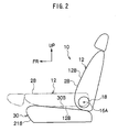
- Fig. 2 shows a side view, viewed from leftward, of the seat 10
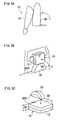
- Fig. 3A shows a perspective view, viewed from diagonally left forward, of the seat 10.
- frontward of the seat 10 is indicated by arrow FR
- upward of the seat 10 is indicated by arrow UP.
- the seat 10 relating to the present embodiment is for a vehicle, and is provided on a cabin floor surface of the vehicle.
- the seat 10 is formed as what is known as a back forward-folding stowing type seat.
- a seat back 12 is provided at the seat 10.
- a left-right direction (width direction) central portion of the seat back 12 is formed as a back main portion 12A, which serves as a seat main portion, along with which each of two left-right direction end portions of the seat back 12 is formed as a back side portion 12B, which serves as a seat side portion.
- the back side portion 12B protrudes to the front side (a face side of the seat back 12).
- a board-form back main frame 16 (side frame) is provided in a pair.
- the back main frame 16 is disposed inside the back side portion 12B.
- a lower end of the back main frame 16 is supported to be tiltable around a tilting center 16A at a vehicle side (a later-described seat cushion 30).
- the seat back 12 is supported to be tiltable around the tilting center 16A at the vehicle side.
- a reclining mechanism 18 is provided at a lower end of the back main frame 16.
- the reclining mechanism 18 locks tilting of the back main frame 16 around the tilting center 16A, and thus the seat back 12 is obstructed from tilting around the tilting center 16A, and is stood up substantially vertically.
- the reclining mechanism 18 By the reclining mechanism 18 being controlled, the reclining mechanism 18 enables tilting of the back main frame 16 around the tilting center 16A, and tilting of the seat back 12 around the tilting center 16A is enabled.
- a back backrest 20 is supported (see Fig. 4A ).
- the back backrest 20 supports a front side region of the back main portion 12A from a rear side.
- First links 22, which structure a back flexing component, are turnably joined, at rear ends, to the back main frame 16 in a predetermined number (two in the present embodiment).
- An upper end of a back joint link 26, which serves as a back joint mechanism, is turnably joined to a lower end of the back sub frame 24 or a front end (anywhere other than a rear end is acceptable) of the first link 22 at the lower portion of the back main frame 16.
- a lower end of the back joint link 26 is turnably joined to the vehicle side at a rear side of the tilting center 16A (a position which is offset from the tilting center 16A) at the lower end of the back main frame 16. Accordingly, turning of the first link 22, the back sub frame 24 and the back joint link 26 is locked, and operation of the back link mechanism 14 is locked.
- the whole of an outer peripheral surface of the seat back 12 is covered with a back face skin 28, which serves as a back cover member (see Fig. 4A ).
- the seat cushion 30 is provided at the front side of the seat back 12.
- the seat cushion 30 is supported at the vehicle side, and is disposed to be substantially horizontal according to a lower side of the seat cushion 30.
- an operation plane of the back link mechanism 14 (a turning plane of the back sub frame 24) is made perpendicular to the left-right direction of the seat back 12. Therefore, a supporting rigidity of the back side portion 12B with respect to a load in the left-right direction of the seat back 12 can be enhanced by the back link mechanism 14, and even when a load in the left-right direction acts on the back side portion 12B from a crew sitting in the seat 10, the back side portion 12B can even more thoroughly retain the crew.
- the seat back 12 is folded onto the upper side of the seat cushion 30, and the seat 10 is stowed (known as fold-forward stowing) (see Fig. 3B ).
- the seat back 12 (the back main frame 16) is tilted forward around the tilting center 16A, and the back joint link 26 is turned forward around the lower end.
- the back sub frame 24 which is to say the first links 22 toward the lower end side of the seat back 12
- the first links 22 are turned toward the lower end side of the seat back 12
- a separation between the back main frame 16 and the back sub frame 24 in a thickness direction of the seat back 12 is contracted (see Fig. 4B ).
- the thickness of the back side portion 12B is contracted in a region at a face side relative to the back main frame 16 and can be reduced in size to be equal to a thickness of the back main portion 12A, and space (space at the upper side of the seat 10) in the cabin at times of stowage of the seat 10 (a luggage compartment) can be made larger.
- a structure can be formed in which the seat 10 is formed as what is known as a tumble-storing type, and after the seat 10 is stowed, support of the seat back 12 and the seat cushion 30 to the vehicle side is released, the seat 10 is turned substantially 90° forward, and thus the seat 10 (the seat back 12 and the seat cushion 30) is stored to the front side in a state of being stood up substantially vertically.
- the thickness of the back side portion 12B has been contracted in accordance with stowing of the seat 10 as described above, space (space at the front side and rear side of the seat 10) in the cabin at times of storage of the seat 10 (a luggage compartment) can be made larger.
- a structure in which the seat 10 is formed as what is known as a space-increasing storage type, and after the seat 10 is stowed, support of the seat back 12 and the seat cushion 30 to the vehicle side is released, the seat 10 is turned substantially 90° to sideward, and thus the seat 10 (the seat back 12 and the seat cushion 30) is stored at the upper side of the wheel housing 32 in a state of being stood up substantially vertically.
- a structure in which the seat 10 is formed as what is known as a rearward under-floor storage type, and after the seat 10 is stowed, support of the seat back 12 and the seat cushion 30 to the vehicle side is released, the seat 10 is turned substantially 180° to rearward or is moved by a turning link or the like, and thus the seat 10 (the seat back 12 and the seat cushion 30) is stored substantially horizontally inside the recess portion 34 in a state in which the seat cushion 30 is disposed at the upper side of the seat back 12.
- a structure is formed in which the lower end of the back joint link 26 is turnably joined to the vehicle side at the rear side of the tilting center 16A at the lower end of the back main frame 16.
- a structure may be formed in which the lower end of the back joint link 26 is turnably joined to the vehicle side at the front side of the tilting center 16A (a position which is offset from the tilting center 16A) at the lower end of the back main frame 16.
- the back sub frame 24 which is to say the first links 22 toward the upper end side of the seat back 12
- the first links 22 are turned toward the upper end side of the seat back 12
- a separation in the seat back 12 thickness direction between the back main frame 16 and the back sub frame 24 is contracted.
- a structure is formed in which the tilting center 16A of the seat back 12 (the back main frame 16) and the lower end (turning center) of the back joint link 26 do not move when the seat 10 is being stowed.
- a structure may be formed in which the tilting center 16A of the seat back 12 (the back main frame 16) and the lower end (turning center) of the back joint link 26 are moved when the seat 10 is being stowed.
- a lower end of a front support link 36 at a front side and a lower end of a rear support link 38 at a rear side are turnably supported at the vehicle side.
- the lower end of the back main frame 16 is supported to be turnable around the tilting center 16A at an upper end of the front support link 36, along with which the lower end of the back main frame 16 is turnably supported at the upper end of the rear support link 38, at the rear side of the tilting center 16A.
- Turning of the back main frame 16 relative to the front support link 36 is locked by the reclining mechanism 18. Accordingly, turning of the back main frame 16, the front support link 36 and the rear support link 38 is locked.
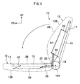
- one end of an intermediate link 38A is non-turnably joined to an upper end of the rear support link 38, and another end of the intermediate link 38A is turnably joined to the lower end of the back joint link 26. Therefore, as shown in Fig.
- the thickness of the back side portion 12B is contracted in the region at the face side relative to the back main frame 16 at times of stowage of the seat 10, and can be made equal to the thickness of the back main portion 12A.
- a structure may be formed in which the seat 10 is formed as what is known as a tilt-down stowage type and, as shown in Fig. 9A , when the seat 10 is being stowed, the seat cushion 30 moves downward and forward in accordance with tilting of the seat back 12 forward around the tilting center 16A, or a structure in which, as shown in Fig. 9B , when the seat 10 is being stowed, the seat cushion 30 moves downward and rearward in accordance with tilting of the seat back 12 forward around the tilting center 16A.
- a structure is formed in which the seat back 12 is folded onto the upper side of the seat cushion 30 and the seat 10 is stowed.
- the seat 10 may be formed with a structure which is known as double-folded stowing. In this case, support of the seat cushion 30 to the vehicle side is released, the seat cushion 30 is turned forward, and thus the seat cushion 30 is stood up substantially vertically. Then, the reclining mechanism 18 is controlled, the seat back 12 turns forward around the back main frame 16, and thus the seat back 12 is disposed substantially horizontally at the rear side of the seat cushion 30 and stowed. Further, as shown in Fig.
- the seat 10 may be formed with a structure which is known as double-flat stowing.
- support of the seat cushion 30 to the vehicle side is released, the seat cushion 30 is turned forward, and thus the seat cushion 30 is inverted to be substantially horizontal.
- the reclining mechanism 18 is controlled, the seat back 12 turns forward around the tilting center 16A, and thus the seat back 12 is disposed substantially horizontally at the rear side of the seat cushion 30 and stowed.
- the thickness of the back side portion 12B is contracted in accordance with stowing of the seat 10 in the same manner as described above. Therefore, space (space at the upper side of the seat back 12) in the cabin at times of stowage of the seat 10 (a luggage compartment) can be made larger, along with which interference of the seat back 12 with the cabin floor surface can be suppressed.
- Fig. 12 shows a side view, viewed from leftward, of principal elements of a seat 40 relating to a second embodiment that is structured with the seat structure of the present invention.
- the seat 40 relating to the present embodiment has a substantially similar structure to the above-described first embodiment, but differs in the following respects.
- a circular rod-shaped control lever 42 which serves as a control mechanism, is joined to the rear end (turning center) of one of the first links 22 at the back main frame 16.
- the control lever 42 is formed as a regulator or the like.
- a turn-locking mechanism (not shown) which serves as a locking mechanism is provided at the control lever 42. Turning of the control lever 42 is obstructed by the turn-locking mechanism, and thus turning of the first links 22 and the back sub frame 24 is locked, and operation of the back link mechanism 14 is restricted.
- the control lever 42 protrudes to sideward of the seat back 12, and by the control lever 42 being turningly controlled, the first links 22 are made turnable.
- back joint link 26 of the above-described first embodiment is not provided in the present embodiment.
- the operation plane of the back link mechanism 14 (the turning plane of the back sub frame 24) is made perpendicular to the left-right direction of the seat back 12. Therefore, a supporting rigidity of the back side portion 12B with respect to a load in the left-right direction of the seat back 12 can be enhanced by the back link mechanism 14, and even when a load in the left-right direction acts on the back side portion 12B from a crew sitting in the seat 10, the back side portion 12B can even more thoroughly retain the crew.
- the first links 22 are turned, and the separation in the seat back 12 thickness direction between the back main frame 16 and the back sub frame 24 is flexed. Accordingly, independently of stowing of the seat 40, the thickness of the back side portion 12B is flexed in the region at the face side relative to the back main frame 16, and can be adjusted.
- Fig. 13 shows a side view, viewed from leftward, of principal elements of a seat 50 relating to a third embodiment that is structured with the seat structure of the present invention.
- Fig. 14 shows a side view, viewed from leftward, of the seat 50.
- the seat 50 relating to the present embodiment has a substantially similar structure to the above-described first embodiment, but differs in the following respects.
- the seat 50 relating to the present embodiment is formed as what is known as a back rearward-folding stowing type.
- the lower end of the back joint link 26 is turnably joined to the vehicle side at the upper side of the tilting center 16A (a position which is offset from the tilting center 16A) at the lower end of the back main frame 16.
- the reclining mechanism 18 is controlled, the seat back 12 is tilted rearward around the tilting center 16A, and thus the seat back 12 is disposed substantially horizontally at the rear side of the seat cushion 30, and the seat 50 is stowed (known as rearward-folding stowing).
- the seat back 12 (the back main frame 16) is tilted rearward around the tilting center 16A, and the back joint link 26 is turned rearward around the lower end.
- the back sub frame 24 which is to say the first links 22 toward the lower end side of the seat back 12
- the first links 22 are turned toward the lower end side of the seat back 12
- the separation in the seat back 12 thickness direction between the back main frame 16 and the back sub frame 24 is contracted.
- the thickness of the back side portion 12B is contracted in the region at the face side relative to the back main frame 16 and can be made equal to the thickness of the back main portion 12A, and space (space at the upper side of the seat back 12) in the cabin at times of stowage of the seat 50 (a luggage compartment) can be made larger.
- a structure in which the seat 50 is formed as what is known as a space-increasing storage type, and after the seat 50 is stowed, support of the seat back 12 and the seat cushion 30 to the vehicle side is released, the seat 50 is turned substantially 90° to sideward, and thus the seat 50 (the seat back 12 and the seat cushion 30) is stored at the upper side of the wheel housing 32 in a state of being stood up substantially vertically.
- a structure is formed in which the lower end of the back joint link 26 is turnably joined to the vehicle side at the upper side of the tilting center 16A at the lower end of the back main frame 16.
- a structure may be formed in which the lower end of the back joint link 26 is turnably joined to the vehicle side at the lower side of the tilting center 16A (a position which is offset from the tilting center 16A) at the lower end of the back main frame 16.
- the seat back 12 the back main frame 16
- the back joint link 26 turns rearward around the lower end.
- the back sub frame 24 which is to say the first links 22 toward the upper end side of the seat back 12
- the first links 22 are turned toward the upper end side of the seat back 12
- a separation in the seat back 12 thickness direction between the back main frame 16 and the back sub frame 24 is contracted.
- Fig. 17 shows a side view, viewed from leftward, of a seat 60 relating to a fourth embodiment that is structured with the seat structure of the present invention.
- the seat 60 relating to the present embodiment has a substantially similar structure to the above-described first embodiment, but differs in the following respects.
- the seat 60 relating to the present embodiment is formed as what is known as a tip-up stowing type.
- a rear end vicinity of the seat cushion 30 is supported at the vehicle side to be turnable around a support shaft 62. Accordingly, the seat cushion 30 is supported at the vehicle side to be turnable around the support shaft 62. A rear end of the seat cushion 30 abuts against the lower end of the seat back 12, and accordingly the seat cushion 30 is disposed substantially horizontally.
- the back joint link 26 is formed in a letter-L shape. An upper end of the back joint link 26 is turnably supported at the lower end of the back sub frame 24 or the front end (anywhere other than the rear end is acceptable) of the first link 22 at the lower portion of the back main frame 16. The lower end of the back joint link 26 is turnably joined to the rear end of the seat cushion 30 (at a position which is offset to the rear side from the support shaft 62). Accordingly, turning of the first links 22, the back sub frame 24 and the back joint link 26 is locked, and operation of the back link mechanism 14 is locked.
- a supporting rigidity from the rear side of the back side portion 12B can be enhanced by the back link mechanism 14 (the back sub frame 24), and even when a load in the left-right direction acts on the back side portion 12B from a crew sitting in the seat 60, the back side portion 12B can thoroughly retain the crew.
- the operation plane of the back link mechanism 14 (the turning plane of the back sub frame 24) is made perpendicular to the left-right direction of the seat back 12. Therefore, a supporting rigidity of the back side portion 12B with respect to a load in the left-right direction of the seat back 12 can be enhanced by the back link mechanism 14, and even when a load in the left-right direction acts on the back side portion 12B from a crew sitting in the seat 10, the back side portion 12B can even more thoroughly retain the crew.
- the seat cushion 30 being turned rearward around the support shaft 62 (which is known as tipping up), the seat cushion 30 is folded up onto the front side of the seat back 12, and the seat 60 is stowed.
- the seat cushion 30 When the seat 60 is being stowed, the seat cushion 30 is tilted rearward around the support shaft 62, and the back joint link 26 is moved downward.
- the back sub frame 24 which is to say the first links 22 downward, the first links 22 are turned downward, and a separation in the seat back 12 thickness direction between the back main frame 16 and the back sub frame 24 is contracted.
- the thickness of the back side portion 12B is contracted in the region at the face side relative to the back main frame 16 and can be made equal to the thickness of the back main portion 12A, and space (space at the front side and rear side of the seat 60) in the cabin at times of stowage of the seat 60 (a luggage compartment) can be made larger.
- a structure can be formed in which the seat 60 is formed as what is known as a tumble-storing type, and after the seat 60 is stowed, support to the vehicle side of the seat back 12 and the seat cushion 30 is released, the seat 60 is turned substantially 180° forward, and thus the seat 60 (the seat back 12 and the seat cushion 30) is stored to the front side in a state of being stood up substantially vertically.
- the thickness of the back side portion 12B has been contracted in accordance with stowing of the seat 60 as described above, space (space at the front side and rear side of the seat 60) in the cabin at times of storage of the seat 60 (a luggage compartment) can be made larger.
- a structure can be formed in which the seat 60 is formed as what is known as a space-increasing storage type, and after the seat 60 is stowed, support of the seat back 12 and the seat cushion 30 to the vehicle side is released, the seat 60 is turned substantially 90° to forward and sideward, and thus the seat 60 (the seat back 12 and the seat cushion 30) is stored at the upper side of the wheel housing 32 in a state of being stood up substantially vertically.
- a structure can be formed in which the seat 60 is formed as what is known as a rearward under-floor storage type, and after the seat 60 is stowed, support of the seat back 12 and the seat cushion 30 to the vehicle side is released, the seat 60 is turned substantially 90° to rearward or is moved by a turning link or the like, and thus the seat 60 (the seat back 12 and the seat cushion 30) is stored substantially horizontally in the recess portion 34 in a state in which the seat cushion 30 is disposed at the upper side of the seat back 12.
- Fig. 18A shows a side view, viewed from leftward, of principal elements of a seat 70 relating to a fifth embodiment that is structured with the seat structure of the present invention.
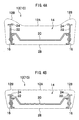
- Fig. 19A shows a sectional view, viewed from upward, of the principal elements of the seat 70.
- the seat 70 relating to the present embodiment has a substantially similar structure to the above-described first embodiment, but differs in the following respects.
- the back backrest 20 structures the back face side frame of the back flexing component, and a predetermined number of the first links 22 are turnably joined, at front ends, to both a left and a right end portion of the back backrest 20.
- a plurality (two in the present embodiment) of second links 72 which structure the back flexing component, are turnably joined at rear ends.
- the back sub frame 24 structures a back face frame of the back flexing component, and is disposed at the front side of the back backrest 20. Front ends of the second links 72 are turnably joined to the back sub frame 24.
- the upper end of the back joint link 26 is turnably joined to a lower end of the back backrest 20 or the front end (anywhere other than the rear end is acceptable) of the first link 22 at the lower portion of the back main frame 16. Accordingly, turning of the first links 22, the back backrest 20 and the back joint link 26 is locked, and operation of the back link mechanism 14 is locked. Further, a rear end of a third link 74, which structures the back flexing component, is turnably joined to the back main frame 16, along with which a front end of the third link 74 is turnably joined to the back sub frame 24 or a position of the second links 72 other than the rear ends (turning centers). Accordingly, turning of the back sub frame 24, the second links 72 and the third link 74 is locked, and operation of the back link mechanism 14 is locked. Therefore, operation of the back link mechanism 14 is locked.
- a third link 74 which structures the back flexing component
- the operation plane of the back link mechanism 14 (the turning plane of the back sub frame 24) is made perpendicular to the left-right direction of the seat back 12. Therefore, a supporting rigidity of the back side portion 12B with respect to a load in the left-right direction of the seat back 12 can be enhanced by the back link mechanism 14, and even when a load in the left-right direction acts on the back side portion 12B from a crew sitting in the seat 10, the back side portion 12B can even more thoroughly retain the crew.
- the seat back 12 is folded onto the upper side of the seat cushion 30, and the seat 70 is stowed (known as fold-forward stowing) (see Fig. 18B ).
- the seat back 12 (the back main frame 16) is tilted forward around the tilting center 16A, and the back joint link 26 is turned forward around the lower end.
- the back backrest 20 which is to say the first links 22 toward the lower end side of the seat back 12
- the first links 22 and the second links 72 are turned toward the lower end side of the seat back 12
- a separation in the seat back 12 thickness direction between the back main frame 16 and the back backrest 20 is contracted, along with which a separation in the seat back 12 thickness direction between the back backrest 20 and the back sub frame 24 is contracted (see Fig. 19B ).
- thicknesses of the back side portion 12B and the back main portion 12A are contracted in the region at the face side relative to the back main frame 16 and can be made equal, and space (space at the upper side of the seat 70) in the cabin at times of stowage of the seat 70 (a luggage compartment) can be made larger.
- a structure is formed in which the lower end of the back joint link 26 is turnably joined to the vehicle side at the rear side of the tilting center 16A at the lower end of the back main frame 16.
- a structure may be formed in which the lower end of the back joint link 26 is turnably joined to the vehicle side at the front side of the tilting center 16A (a position which is offset from the tilting center 16A) at the lower end of the back main frame 16.
- the back backrest 20 which is to say the first links 22 toward the upper end side of the seat back 12
- the first links 22 and the second links 72 are turned toward the upper end side of the seat back 12
- the separation in the seat back 12 thickness direction between the back main frame 16 and the back backrest 20 is contracted, along with which the separation in the seat back 12 thickness direction between the back backrest 20 and the back sub frame 24 is contracted (see Fig. 20B ).
- a structure is formed in which the tilting center 16A of the seat back 12 (the back main frame 16) and the lower end (turning center) of the back joint link 26 do not move when the seat 70 is being stowed.
- a structure may be formed in which the tilting center 16A of the seat back 12 (the back main frame 16) and the lower end (turning center) of the back joint link 26 are moved (for example, movement to the rear side) when the seat 70 is being stowed, in a similar manner to Figs. 7A and 7B .
- a structure may be formed in which the seat 70 is formed as what is known as a tilt-down stowage type, similarly to the above-described first embodiment (see Figs. 9A and 9B ).
- a structure is formed in which the seat back 12 is folded onto the upper side of the seat cushion 30 and the seat 70 is stowed.
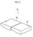
- the seat 70 may be formed with a structure which is known as double-folded stowing (see Fig. 10 ), or the seat 70 may be formed with a structure which is known as double-flat stowing (see Fig. 11 ).
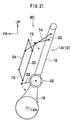
- Fig. 21 shows a side view, viewed from leftward, of principal elements of a seat 80 relating to a sixth embodiment that is structured with the seat structure of the present invention.
- the seat 80 relating to the present embodiment has a substantially similar structure to the above-described fifth embodiment, but differs in the following respects.
- the circular rod-shaped control lever 42 which serves as the control mechanism, is joined to the rear end (turning center) of one of the first links 22 at the back main frame 16.
- the control lever 42 is formed as a dial-type regulator or the like.
- a turn-locking mechanism (not shown), which serves as a locking mechanism, is provided at the control lever 42. Turning of the control lever 42 is obstructed by the turn-locking mechanism, and thus turning of the first links 22, the back backrest 20, the second links 72, the back sub frame 24 and the third link 74 is locked, and operation of the back link mechanism 14 is locked.
- the control lever 42 protrudes to sideward of the seat back 12, and by the control lever 42 being turningly controlled, the first links 22 are made turnable.
- back joint link 26 of the above-described fifth embodiment is not provided in the present embodiment.
- the operation plane of the back link mechanism 14 (the turning plane of the back sub frame 24) is made perpendicular to the left-right direction of the seat back 12. Therefore, a supporting rigidity of the back side portion 12B with respect to a load in the left-right direction of the seat back 12 can be enhanced by the back link mechanism 14, and even when a load in the left-right direction acts on the back side portion 12B from a crew sitting in the seat 10, the back side portion 12B can even more thoroughly retain the crew.
- the first links 22 are turned and the separation in the seat back 12 thickness direction between the back main frame 16 and the back backrest 20 is flexed, along with which the second links 72 are turned and the separation in the seat back 12 thickness direction between the back backrest 20 and the back sub frame 24 is flexed. Accordingly, independently of stowing of the seat 80, thicknesses of the back side portion 12B and the back main portion 12A are flexed in the region at the face side relative to the back main frame 16, and can be adjusted.
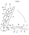
- Fig. 22 shows a side view, viewed from leftward, of principal elements of a seat 90 relating to a seventh embodiment that is structured with the seat structure of the present invention.
- the seat 90 relating to the present embodiment has a substantially similar structure to the above-described fifth embodiment, but differs in the following respects.
- the seat 90 relating to the present embodiment is formed as what is known as a back rearward-folding stowing type.
- the lower end of the back joint link 26 is turnably joined to the vehicle side at the upper side of the tilting center 16A (a position which is offset from the tilting center 16A) at the lower end of the back main frame 16.
- the reclining mechanism 18 is controlled, the seat back 12 is tilted rearward around the tilting center 16A, and thus the seat back 12 is disposed substantially horizontally at the rear side of the seat cushion 30, and the seat 90 is stowed (known as rearward-folding stowing).
- the seat back 12 (the back main frame 16) is tilted rearward around the tilting center 16A, and the back joint link 26 is turned rearward around the lower end.
- the back backrest 20 which is to say the first links 22 toward the lower end side of the seat back 12
- the first links 22 and the second links 72 are turned toward the lower end side of the seat back 12
- the separation in the seat back 12 thickness direction between the back main frame 16 and the back backrest 20 is contracted, along with which the separation in the seat back 12 thickness direction between the back backrest 20 and the back sub frame 24 is contracted.
- the thicknesses of the back side portion 12B and the back main portion 12A are contracted in the region at the face side relative to the back main frame 16 and can be made equal, and space (space at the upper side of the seat back 12) in the cabin at times of stowage of the seat 90 (a luggage compartment) can be made larger.
- a structure can be formed in which the seat 90 is formed as what is known as a space-increasing storage type (see Fig. 15 ).
- a structure is formed in which the lower end of the back joint link 26 is turnably joined to the vehicle side at the upper side of the tilting center 16A at the lower end of the back main frame 16.
- a structure may be formed in which the lower end of the back joint link 26 is turnably joined to the vehicle side at the lower side of the tilting center 16A (a position which is offset from the tilting center 16A) at the lower end of the back main frame 16.
- the back backrest 20 which is to say the first links 22 toward the upper end side of the seat back 12
- the first links 22 and the second links 72 are turned toward the upper end side of the seat back 12
- the separation in the seat back 12 thickness direction between the back main frame 16 and the back backrest 20 is contracted, along with which the separation in the seat back 12 thickness direction between the back backrest 20 and the back sub frame 24 is contracted.
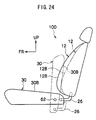
- Fig. 24 shows a side view, viewed from leftward, of a seat 100 relating to an eighth embodiment that is structured with the seat structure of the present invention.
- the seat 100 relating to the present embodiment has a substantially similar structure to the above-described fifth embodiment (see Fig. 18A ), but differs in the following respects.
- the seat 100 relating to the present embodiment is formed as what is known as a tip-up stowing type.
- the rear end vicinity of the seat cushion 30 is supported at the vehicle side to be turnable around the support shaft 62, at both the left and the right end portion. Accordingly, the seat cushion 30 is supported at the vehicle side to be turnable around the support shaft 62. The rear end of the seat cushion 30 abuts against the lower end of the seat back 12, and accordingly the seat cushion 30 is disposed substantially horizontally.
- the back joint link 26 is formed in the letter-L shape.
- the upper end of the back joint link 26 is turnably joined to the lower end of the back backrest 20 or the front end (anywhere other than the rear end is acceptable) of the first link 22 at the lower portion of the back main frame 16.
- the lower end of the back joint link 26 is turnably joined to the rear end of the seat cushion 30 (at a position which is offset to the rear side from the support shaft 62). Accordingly, turning of the first links 22, the back backrest 20, the back joint link 26, the second links 72, the back sub frame 24 and the third link 74 is locked, and operation of the back link mechanism 14 is restricted.
- a supporting rigidity from the rear side of the back side portion 12B can be enhanced by the back link mechanism 14 (the back sub frame 24), and even when a load in the left-right direction acts on the back side portion 12B from a crew sitting in the seat 100, the back side portion 12B can thoroughly retain the crew.
- the operation plane of the back link mechanism 14 (the turning plane of the back sub frame 24) is made perpendicular to the left-right direction of the seat back 12. Therefore, a supporting rigidity of the back side portion 12B with respect to a load in the left-right direction of the seat back 12 can be enhanced by the back link mechanism 14, and even when a load in the left-right direction acts on the back side portion 12B from a crew sitting in the seat 10, the back side portion 12B can even more thoroughly retain the crew.
- the seat cushion 30 being turned rearward around the support shaft 62 (which is known as tipping up), the seat cushion 30 is folded up onto the front side of the seat back 12, and the seat 100 is stowed.
- the seat cushion 30 When the seat 100 is being stowed, the seat cushion 30 is tilted rearward around the support shaft 62, and the back joint link 26 is moved downward.
- the back backrest 20 which is to say the first links 22 downward, the first links 22 and the second links 72 are turned toward the lower end side, and the separation in the seat back 12 thickness direction between the back main frame 16 and the back backrest 20 is contracted, along with which the separation in the seat back 12 thickness direction between the back backrest 20 and the back sub frame 24 is contracted.
- the thicknesses of the back side portion 12B and the back main portion 12A are contracted in the region at the face side relative to the back main frame 16 and can be made equal, and space (space at the front side and rear side of the seat 100) in the cabin at times of stowage of the seat 100 (a luggage compartment) can be made larger.
- this can have a structure in which the seat 100 is formed as what is known as a tumble-storing type (see Fig. 5A ), a structure in which the seat 100 is formed as what is known as a space-increasing storage type (see Fig. 5B ), or a structure in which the seat 100 is formed as what is known as a rearward under-floor storage type (see Fig. 5C ).
- Fig. 25 shows a side view, viewed from leftward, of principal elements of a seat 110 relating to a ninth embodiment that is structured with the seat structure of the present invention.
- the seat 110 relating to the present embodiment has a substantially similar structure to the above-described first embodiment, but differs in the following respects.
- the first links 22 are provided extending rearward, and the first links 22 are turnably joined to the back main frame 16 at intermediate portions.
- a board-form back frame 112 is provided inside the seat back 12, at the rear side of the back main frame 16, a board-form back frame 112 is provided, which serves as a back reverse side frame of the back flexing component.
- the back frame 112 is turnably joined to the rear ends of the first links 22. Furthermore, the back frame 112 is covered with the back face skin 28 and accommodated, and therefore appearance of the seat back 12 is improved.
- the upper end of the back joint link 26 is turnably joined to the lower end of the back sub frame 24, the first link 22 at the lower portion of the back main frame 16 (anywhere other than a position of joining to the back main frame 16 is acceptable), or a lower end of the back frame 112. Accordingly, turning of the first links 22, the back sub frame 24, the back frame 112 and the back joint link 26 is locked, and operation of the back link mechanism 14 is restricted.
- the operation plane of the back link mechanism 14 (the turning plane of the back sub frame 24) is made perpendicular to the left-right direction of the seat back 12. Therefore, a supporting rigidity of the back side portion 12B with respect to a load in the left-right direction of the seat back 12 can be enhanced by the back link mechanism 14, and even when a load in the left-right direction acts on the back side portion 12B from a crew sitting in the seat 10, the back side portion 12B can even more thoroughly retain the crew.
- the seat back 12 is folded onto the upper side of the seat cushion 30, and the seat 110 is stowed (known as fold-forward stowing).
- the seat back 12 (the back main frame 16) is tilted forward around the tilting center 16A, and the back joint link 26 is turned forward around the lower end.
- the back sub frame 24 and the first links 22 or the back frame 112 toward the lower end side of the seat back 12, the first links 22 are turned, and separations in the seat back 12 thickness direction between the back main frame 16 and the back sub frame 24 and the back frame 112 are contracted.
- the thickness of the back side portion 12B is contracted in the region at the face side relative to the back main frame 16, along with which the thicknesses of the back side portion 12B and the back main portion 12A are contracted in a region at the reverse side relative to the back main frame 16, the thicknesses of the back side portion 12B and the back main portion 12A can be made equal, and space (space at the upper side of the seat 110) in the cabin at times of stowage of the seat 110 (a luggage compartment) can be made larger.
- the back frame 112 is provided inside the seat back 12 and has a structure which is turnably joined to the rear ends of the first links 22.
- the back frame 112 may have a structure that is formed in a character- ⁇ shape in cross-section (a back board) and provided outside a rear side of the seat back 12.
- compression coil springs 114 span across between the back backrest 20 and the back frame 112.
- the back frame 112 is abutted against the rear ends of the first links 22 by urging force of the compression coil springs 114 and is turnably joined. Therefore, as shown in Fig.
- a structure is formed in which the lower end of the back joint link 26 is turnably joined to the vehicle side at the front side of the tilting center 16A at the lower end of the back main frame 16.
- a structure may be formed in which the lower end of the back joint link 26 is turnably joined to the vehicle side at the front side of the tilting center 16A (a position which is offset from the tilting center 16A) at the lower end of the back main frame 16.
- a structure is formed in which the tilting center 16A of the seat back 12 (the back main frame 16) and the lower end (turning center) of the back joint link 26 do not move when the seat 110 is being stowed.
- a structure may be formed in which the tilting center 16A of the seat back 12 (the back main frame 16) and the lower end (turning center) of the back joint link 26 are moved (for example, movement to rearward) when the seat 110 is being stowed, in a similar manner to Figs. 7A and 7B .
- a structure may be formed in which the seat 110 is formed as what is known as a tilt-down stowage type, similarly to the above-described first embodiment (see Figs. 9A and 9B ).
- a structure is formed in which the seat back 12 is folded onto the upper side of the seat cushion 30 and the seat 110 is stowed.
- the seat 110 may be formed with a structure which is known as double-folded stowing (see Fig. 10 ), or the seat 110 may be formed with a structure which is known as double-flat stowing (see Fig. 11 ).
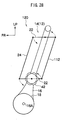
- Fig. 28 shows a side view, viewed from leftward, of principal elements of a seat 120 relating to a tenth embodiment that is structured with the seat structure of the present invention.
- the seat 120 relating to the present embodiment has a substantially similar structure to the above-described ninth embodiment, but differs in the following respects.
- the circular rod-shaped control lever 42 which serves as the control mechanism, is engaged with an intermediate portion (turning center) of one of the first links 22 at the back main frame 16.
- the control lever 42 is formed as a dial-type regulator or the like.
- a turn-locking mechanism (not shown) which serves as the locking mechanism is provided at the control lever 42. Turning of the control lever 42 is obstructed by the turn-locking mechanism, and thus turning of the first links 22, the back sub frame 24 and the back frame 112 is locked, and operation of the back link mechanism 14 is locked.
- the control lever 42 protrudes to sideward of the seat back 12, and by the control lever 42 being turningly controlled, the first links 22 are made turnable.
- back joint link 26 of the above-described ninth embodiment is not provided in the present embodiment.
- the operation plane of the back link mechanism 14 (the turning plane of the back sub frame 24) is made perpendicular to the left-right direction of the seat back 12. Therefore, a supporting rigidity of the back side portion 12B with respect to a load in the left-right direction of the seat back 12 can be enhanced by the back link mechanism 14, and even when a load in the left-right direction acts on the back side portion 12B from a crew sitting in the seat 10, the back side portion 12B can even more thoroughly retain the crew.
- the first links 22 are turned and the separations in the seat back 12 thickness direction between the back main frame 16 and the back sub frame 24 and the back frame 112 are flexed. Accordingly, independently of stowing of the seat 120, the thickness of the back side portion 12B is flexed in the region at the face side relative to the back main frame 16, along with which the thicknesses of the back side portion 12B and the back main portion 12A are flexed in the region at the reverse side relative to the back main frame 16, and thicknesses of the back side portion 12B and the back main portion 12A can be adjusted.
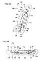
- Fig. 29 shows a side view, viewed from leftward, of principal elements of a seat 130 relating to an eleventh embodiment that is structured with the seat structure of the present invention.
- the seat 130 relating to the present embodiment has a substantially similar structure to the above-described ninth embodiment, but differs in the following respects.
- the seat 130 relating to the present embodiment is formed as what is known as a back rearward-folding stowing type.
- the lower end of the back joint link 26 is turnably joined to the vehicle side at the upper side of the tilting center 16A (a position which is offset from the tilting center 16A) at the lower end of the back main frame 16.
- the reclining mechanism 18 is controlled, the seat back 12 is tilted rearward around the tilting center 16A, and thus the seat back 12 is disposed substantially horizontally at the rear side of the seat cushion 30, and the seat 130 is stowed (known as rearward-folding stowing).
- the seat back 12 (the back main frame 16) is tilted rearward around the tilting center 16A, and the back joint link 26 is turned rearward around the lower end.
- the back sub frame 24 and the first links 22 or the back frame 112 toward the lower end side of the seat back 12, the first links 22 are turned, and the separations in the seat back 12 thickness direction between the back main frame 16 and the back sub frame 24 and the back frame 112 are contracted.
- the thickness of the back side portion 12B is contracted in the region at the face side relative to the back main frame 16, along with which the thicknesses of the back side portion 12B and the back main portion 12A are contracted in the region at the reverse side relative to the back main frame 16, thicknesses of the back side portion 12B and the back main portion 12A can be made equal, and space (space at the upper side of the seat back 12) in the cabin at times of stowage of the seat 130 (a luggage compartment) can be made larger.
- a structure can be formed in which the seat 130 is formed as what is known as a space-increasing storage type (see Fig. 15 ).
- a structure is formed in which the lower end of the back joint link 26 is turnably joined to the vehicle side at the upper side of the tilting center 16A at the lower end of the back main frame 16.
- a structure may be formed in which the lower end of the back joint link 26 is turnably joined to the vehicle side at the lower side of the tilting center 16A (a position which is offset from the tilting center 16A) at the lower end of the back main frame 16.
- Fig. 31 shows a side view, viewed from leftward, of a seat 140 relating to a twelfth embodiment that is structured with the seat structure of the present invention.
- the seat 140 relating to the present embodiment has a substantially similar structure to the above-described ninth embodiment (see Fig. 25 ), but differs in the following respects.
- the seat 140 relating to the present embodiment is formed as what is known as a tip-up stowing type.
- the rear end vicinity of the seat cushion 30 is supported at the vehicle side to be turnable around the support shaft 62, at both the left and the right end portion. Accordingly, the seat cushion 30 is supported at the vehicle side to be turnable around the support shaft 62. The rear end of the seat cushion 30 abuts against the lower end of the seat back 12, and accordingly the seat cushion 30 is disposed substantially horizontally.
- the back joint link 26 is formed in the letter-L shape.
- the upper end of the back joint link 26 is turnably joined to the lower end of the back sub frame 24, the first link 22 at the lower portion of the back main frame 16 (anywhere other than the position of joining to the back main frame 16 is acceptable), or the lower end of the back frame 112.
- the lower end of the back joint link 26 is turnably joined to the rear end of the seat cushion 30 (at a position which is offset to the rear side from the support shaft 62). Accordingly, turning of the first links 22, the back sub frame 24, the back frame 112 and the back joint link 26 is locked, and operation of the back link mechanism 14 is restricted.
- a supporting rigidity from the rear side of the back side portion 12B can be enhanced by the back link mechanism 14 (the back sub frame 24), and even when a load in the left-right direction acts on the back side portion 12B from a crew sitting in the seat 140, the back side portion 12B can thoroughly retain the crew.
- the operation plane of the back link mechanism 14 (the turning plane of the back sub frame 24) is made perpendicular to the left-right direction of the seat back 12. Therefore, a supporting rigidity of the back side portion 12B with respect to a load in the left-right direction of the seat back 12 can be enhanced by the back link mechanism 14, and even when a load in the left-right direction acts on the back side portion 12B from a crew sitting in the seat 10, the back side portion 12B can even more thoroughly retain the crew.
- the seat cushion 30 being turned rearward around the support shaft 62 (known as tipping up), the seat cushion 30 is folded up onto the front side of the seat back 12, and the seat 140 is stowed.
- the seat cushion 30 When the seat 140 is being stowed, the seat cushion 30 is tilted rearward around the support shaft 62, and the back joint link 26 is moved downward. Thus, by movement of the back sub frame 24 and the first links 22 or the back frame 112 downward, the first links 22 are turned, and the separations in the seat back 12 thickness direction between the back main frame 16 and the back sub frame 24 and the back frame 112 are contracted.
- the thickness of the back side portion 12B for times of usual use is made thicker, in accordance with stowing of the seat 140, the thickness of the back side portion 12B is contracted in the region at the face side relative to the back main frame 16, along with which the thicknesses of the back side portion 12B and the back main portion 12A are contracted in the region at the rear side relative to the back main frame 16, the thicknesses of the back side portion 12B and the back main portion 12A can be made equal, and space (space at the front side and rear side of the seat 100) in the cabin at times of stowage of the seat 140 (a luggage compartment) can be made larger.
- this can have a structure in which the seat 140 is formed as what is known as a tumble-storing type (see Fig. 5A ), a structure in which the seat 140 is formed as what is known as a space-increasing storage type (see Fig. 5B ), or a structure in which the seat 140 is formed as what is known as a rearward under-floor storage type (see Fig. 5C ).
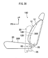
- Fig. 32A shows a side view, viewed from leftward, of principal elements of a seat 150 relating to a thirteenth embodiment that is structured with the seat structure of the present invention.
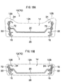
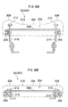
- Fig. 33A shows a sectional view, viewed from above, of the principal elements of the seat 150.
- the seat 150 relating to the present embodiment has a substantially similar structure to the above-described fifth embodiment, but differs in the following respects.
- the first links 22 are provided extending rearward, and the first links 22 are turnably joined to the back main frame 16 at intermediate portions.
- the board-form back frame 112 which serves as the back reverse side frame of the back flexing component is provided inside the seat back 12, at the rear side of the back main frame 16, the board-form back frame 112 which serves as the back reverse side frame of the back flexing component is provided.
- the back frame 112 is turnably joined to the rear ends of the first links 22. Further, the back frame 112 is covered with the back face skin 28 and accommodated, and therefore appearance of the seat back 12 is improved.
- the upper end of the back joint link 26 is turnably joined to the lower end of the back backrest 20, the first link 22 at the lower portion of the back main frame 16 (anywhere other than a position of joining to the back main frame 16 is acceptable), or the lower end of the back frame 112. Accordingly, turning of the first links 22, the back backrest 20, the back frame 112, the back joint link 26, the second links 72, the back sub frame 24 and the third link 74 is locked, and operation of the back link mechanism 14 is restricted.
- the operation plane of the back link mechanism 14 (the turning plane of the back sub frame 24) is made perpendicular to the left-right direction of the seat back 12. Therefore, a supporting rigidity of the back side portion 12B with respect to a load in the left-right direction of the seat back 12 can be enhanced by the back link mechanism 14, and even when a load in the left-right direction acts on the back side portion 12B from a crew sitting in the seat 10, the back side portion 12B can even more thoroughly retain the crew.
- the seat back 12 is folded onto the upper side of the seat cushion 30, and the seat 150 is stowed (known as fold-forward stowing) (see Fig. 32B ).
- the seat back 12 (the back main frame 16) is tilted forward around the tilting center 16A, and the back joint link 26 is turned forward around the lower end.
- the first links 22 and the second links 72 are turned, and separations in the seat back 12 thickness direction between the back main frame 16 and the back backrest 20 and the back frame 112 are contracted (see Fig. 33B ).
- the thicknesses of the back side portion 12B and the back main portion 12A for times of usual use are made thicker, in accordance with stowing of the seat 150, the thicknesses of the back side portion 12B and the back main portion 12A are contracted in the region at the face side and the region at the reverse side relative to the back main frame 16 and can be made equal, and space (space at the upper side of the seat 150) in the cabin at times of stowage of the seat 150 (a luggage compartment) can be made larger.
- a structure is formed in which the lower end of the back joint link 26 is turnably joined to the vehicle side at the rear side of the tilting center 16A at the lower end of the back main frame 16.
- a structure may be formed in which the lower end of the back joint link 26 is turnably joined to the vehicle side at the front side of the tilting center 16A (a position which is offset from the tilting center 16A) at the lower end of the back main frame 16.
- the first links 22 and the second links 72 are turned, and the separations in the seat back 12 thickness direction between the back main frame 16 and the back backrest 20 and the back frame 112 are contracted, along with which a separation in the seat back 12 thickness direction between the back backrest 20 and the back sub frame 24 is contracted (see Fig. 34B ).
- a structure is formed in which the tilting center 16A of the seat back 12 (the back main frame 16) and the lower end (turning center) of the back joint link 26 do not move when the seat 150 is being stowed.
- a structure may be formed in which the tilting center 16A of the seat back 12 (the back main frame 16) and the lower end (turning center) of the back joint link 26 are moved (for example, movement rearward) when the seat 150 is being stowed, in a similar manner to Figs. 7A and 7B .
- a structure may be formed in which the seat 150 is formed as what is known as a tilt-down stowage type, similarly to the above-described first embodiment (see Figs. 9A and 9B ).
- a structure is formed in which the seat back 12 is folded onto the upper side of the seat cushion 30 and the seat 150 is stowed.
- the seat 150 may be formed with a structure which is known as double-folded stowing (see Fig. 10 ), or the seat 110 may be formed with a structure which is known as double-flat stowing (see Fig. 11 ).
- Fig. 35 shows a side view, viewed from leftward, of principal elements of a seat 160 relating to a fourteenth embodiment that is structured with the seat structure of the present invention.
- the seat 160 relating to the present embodiment has a substantially similar structure to the above-described thirteenth embodiment, but differs in the following respects.
- the circular rod-shaped control lever 42 which serves as the control mechanism, is engaged with an intermediate portion (turning center) of one of the first links 22 at the back main frame 16.
- the control lever 42 is formed as a dial-type regulator or the like.
- a turn-locking mechanism (not shown) which serves as the locking mechanism is provided at the control lever 42. Turning of the control lever 42 is obstructed by the turn-locking mechanism, and thus turning of the first links 22, the back backrest 20, the back frame 112, the second links 72, the back sub frame 24 and the third link 74 is locked, and operation of the back link mechanism 14 is restricted.
- the control lever 42 protrudes to sideward of the seat back 12, and by the control lever 42 being turningly controlled, the first links 22 are made turnable.
- back joint link 26 of the above-described thirteenth embodiment is not provided in the present embodiment.
- the operation plane of the back link mechanism 14 (the turning plane of the back sub frame 24) is made perpendicular to the left-right direction of the seat back 12. Therefore, a supporting rigidity of the back side portion 12B with respect to a load in the left-right direction of the seat back 12 can be enhanced by the back link mechanism 14, and even when a load in the left-right direction acts on the back side portion 12B from a crew sitting in the seat 10, the back side portion 12B can even more thoroughly retain the crew.
- the first links 22 are turned and the separations in the seat back 12 thickness direction between the back main frame 16 and the back backrest 20 and the back frame 112 are flexed, along with which the second links 72 are turned and a separation in the seat back 12 thickness direction between the back backrest 20 and the back sub frame 24 is flexed. Accordingly, independently of stowing of the seat 160, the thicknesses of the back side portion 12B and the back main portion 12A are flexed in the region at the front side and region at the reverse side relative to the back main frame 16, and can be adjusted.
- Fig. 36 shows a side view, viewed from leftward, of principal elements of a seat 170 relating to a fifteenth embodiment that is structured with the seat structure of the present invention.
- the seat 170 relating to the present embodiment has a substantially similar structure to the above-described thirteenth embodiment, but differs in the following respects.
- the seat 170 relating to the present embodiment is formed as what is known as a back rearward-folding stowing type.
- the lower end of the back joint link 26 is turnably joined to the vehicle side at the upper side of the tilting center 16A (a position which is offset from the tilting center 16A) at the lower end of the back main frame 16.
- the reclining mechanism 18 is controlled, the seat back 12 is tilted rearward around the tilting center 16A, and thus the seat back 12 is disposed substantially horizontally at the rear side of the seat cushion 30, and the seat 170 is stowed (known as rearward-folding stowing).
- the seat back 12 (the back main frame 16) is tilted rearward around the tilting center 16A, and the back joint link 26 is turned rearward around the lower end.
- the first links 22 and the second links 72 are turned, and the separations in the seat back 12 thickness direction between the back main frame 16 and the back backrest 20 and the back frame 112 are contracted, along with which the separation in the seat back 12 thickness direction between the back backrest 20 and the back sub frame 24 is contracted.
- the thicknesses of the back side portion 12B and the back main portion 12A for times of usual use are made thicker, in accordance with stowing of the seat 170, the thicknesses of the back side portion 12B and the back main portion 12A are contracted in the region at the face side and region at the reverse side relative to the back main frame 16 and can be made equal, and space (space at the upper side of the seat back 12) in the cabin at times of stowage of the seat 170 (a luggage compartment) can be made larger.
- a structure can be formed in which the seat 170 is formed as what is known as a space-increasing storage type (see Fig. 15 ).
- a structure is formed in which the lower end of the back joint link 26 is turnably joined to the vehicle side at the upper side of the tilting center 16A at the lower end of the back main frame 16.
- a structure may be formed in which the lower end of the back joint link 26 is turnably joined to the vehicle side at the lower side of the tilting center 16A (a position which is offset from the tilting center 16A) at the lower end of the back main frame 16.
- the first links 22 and the second links 72 are turned, and the separations in the seat back 12 thickness direction between the back main frame 16 and the back backrest 20 and the back frame 112 are contracted, along with which the separation in the seat back 12 thickness direction between the back backrest 20 and the back sub frame 24 is contracted.
- Fig. 38 shows a side view, viewed from leftward, of a seat 180 relating to a sixteenth embodiment that is structured with the seat structure of the present invention.
- the seat 180 relating to the present embodiment has a substantially similar structure to the above-described thirteenth embodiment (see Fig. 32A ), but differs in the following respects.
- the seat 180 relating to the present embodiment is formed as what is known as a tip-up stowing type.
- the rear end vicinity of the seat cushion 30 is supported at the vehicle side to be turnable around the support shaft 62, at both the left and the right end portion. Accordingly, the seat cushion 30 is supported at the vehicle side to be turnable around the support shaft 62. The rear end of the seat cushion 30 abuts against the lower end of the seat back 12, and accordingly the seat cushion 30 is disposed substantially horizontally.
- the back joint link 26 is formed in the letter-L shape.
- the upper end of the back joint link 26 is turnably joined to the lower end of the back backrest 20, the first link 22 at the lower portion of the back main frame 16 (anywhere other than the position of joining to the back main frame 16 is acceptable), or the lower end of the back frame 112.
- the lower end of the back joint link 26 is turnably joined to the rear end of the seat cushion 30 (at a position which is offset to the rear side from the support shaft 62). Accordingly, turning of the first links 22, the back backrest 20, the back frame 112, the back joint link 26, the second links 72, the back sub frame 24 and the third link 74 is locked, and operation of the back link mechanism 14 is restricted.
- a supporting rigidity from the rear side of the back side portion 12B can be enhanced by the back link mechanism 14 (the back sub frame 24), and even when a load in the left-right direction acts on the back side portion 12B from a crew sitting in the seat 180, the back side portion 12B can thoroughly retain the crew.
- the operation plane of the back link mechanism 14 (the turning plane of the back sub frame 24) is made perpendicular to the left-right direction of the seat back 12. Therefore, a supporting rigidity of the back side portion 12B with respect to a load in the left-right direction of the seat back 12 can be enhanced by the back link mechanism 14, and even when a load in the left-right direction acts on the back side portion 12B from a crew sitting in the seat 10, the back side portion 12B can even more thoroughly retain the crew.
- the seat cushion 30 being turned rearward around the support shaft 62 (known as tipping up), the seat cushion 30 is folded up onto the front side of the seat back 12, and the seat 180 is stowed.
- the seat cushion 30 When the seat 180 is being stowed, the seat cushion 30 is tilted rearward around the support shaft 62, and the back joint link 26 is moved downward.
- the first links 22 and the second links 72 are turned, and the separations in the seat back 12 thickness direction between the back main frame 16 and the back backrest 20 and the back frame 112 are contracted, along with which the separation in the seat back 12 thickness direction between the back backrest 20 and the back sub frame 24 is contracted.
- the thicknesses of the back side portion 12B and the back main portion 12A for times of usual use are made thicker, in accordance with stowing of the seat 180, the thicknesses of the back side portion 12B and the back main portion 12A are contracted in the region at the face side and region at the reverse side relative to the back main frame 16 and can be made equal, and space (space at the front side and rear side of the seat 180) in the cabin at times of stowage of the seat 180 (a luggage compartment) can be made larger.
- this can have a structure in which the seat 180 is formed as what is known as a tumble-storing type (see Fig. 5A ), a structure in which the seat 180 is formed as what is known as a space-increasing storage type (see Fig. 5B ), or a structure in which the seat 180 is formed as what is known as a rearward under-floor storage type (see Fig. 5C ).
- the back frame 112 is provided inside the seat back 12 and has a structure which is turnably joined to the rear ends of the first links 22.
- the back frame 112 may have a structure that is formed in a character- ⁇ shape in cross-section (a back board) and provided outside a rear side of the seat back 12.
- the whole of an outer peripheral surface of the back frame 112 may be covered with an additional back face skin (not shown) which serves as the back cover member similarly to the back face skin 28. Accordingly, appearance of the seat back 12 can be improved.
- Fig. 39A shows a side view, viewed from leftward, of principal elements of a seat 200 relating to a seventeenth embodiment that is structured with the seat structure of the present invention.
- Fig. 40A shows a sectional view, viewed from forward, of the principal elements of the seat 200.
- the seat 200 relating to the present embodiment is for a vehicle, and is provided on a cabin floor surface 202 of the vehicle.
- the seat 200 is formed as what is known as a back forward-folding stowing type seat.
- the seat back 12 is provided at the seat 200.
- the board-form back main frame 16 (see Fig. 1 ) is provided inside each of two left-right direction end portions of the seat back 12, and the lower end of the back main frame 16 is supported at the vehicle side to be tiltable around the tilting center 16A.
- the reclining mechanism 18 is provided at the lower end of the back main frame 16.
- the reclining mechanism 18 locks tilting of the back main frame 16 around the tilting center 16A, and thus the seat back 12 is obstructed from tilting around the tilting center 16A, and is stood up substantially vertically.
- the reclining mechanism 18 By the reclining mechanism 18 being controlled, the reclining mechanism 18 enables tilting of the back main frame 16 around the tilting center 16A, and tilting of the seat back 12 around the tilting center 16A is enabled.
- the seat cushion 30 is provided at the front side of the seat back 12.
- the seat cushion 30 is horizontally disposed in a state in which the rear end is disposed in a vicinity of the lower end of the seat back 12.
- a left-right direction (width direction) central portion of the seat cushion 30 is formed as a cushion main portion 30A, which serves as a seat main portion, and each of two left-right direction side portions of the seat cushion 30 is formed as a cushion side portion 30B, which serves as a seat side portion.
- the cushion side portion 30B protrudes to the upper side (the face side of the seat cushion 30) in comparison with the cushion main portion 30A (see Fig. 3A ).
- a cushion link mechanism 204 which serves as the link mechanism, is provided inside the seat cushion 30.
- a rectangular frame-form cushion main frame 206 is provided at the cushion link mechanism 204. Two left and right side portions of the cushion main frame 206 are disposed inside the cushion side portions 30B.
- a cushion support portion 208 supports between two left and right side regions of the cushion main frame 206. The cushion support portion 208 supports an upper side region of the cushion main portion 30A from the lower side.
- a lower end of an arm 210 is non-turnably joined to a rear portion of the cushion main frame 206.
- An upper end of the arm 210 is turnably joined to the lower portion of the back main frame 16 at the upper side of the tilting center 16A (a position which is offset from the tilting center 16A).
- a rear end of a board-form cushion sub frame 212 which serves as a cushion face side frame of a cushion flexing component, is turnably joined by a cushion joint shaft 214, which serves as a cushion joining component of the cushion flexing component.
- the cushion sub frame 212 is disposed at the upper side of the cushion main frame 206, and supports an upper side region of the cushion side portion 30B from the lower side.
- a cushion front link 216 which serves as a cushion connection mechanism, is turnably joined, at an intermediate portion.
- the cushion front link 216 is turnably joined to the vehicle side at a lower end, along with which it supports, at an upper end, the lower side of the cushion sub frame 212. Accordingly, the seat cushion 30 is supported at the vehicle side, turning of the cushion main frame 206, the arm 210, the cushion front link 216 and the cushion sub frame 212 is locked, and operation of the cushion link mechanism 204 is restricted.
- the whole of an outer peripheral surface of the seat cushion 30 is covered with a cushion face skin 218, which serves as a cushion cover member.
- the cushion front link 216 is turnably joined to the vehicle side.
- the cushion main frame 206 the arm 210, the cushion front link 216 and the cushion sub frame 212 is locked, and operation of the cushion link mechanism 204 is locked. Therefore, a supporting rigidity of the cushion side portion 30B from the lower side can be enhanced by the cushion link mechanism 204 (the cushion sub frame 212), and even when a load in the left-right direction acts on the cushion side portion 30B from a crew sitting in the seat 200, the cushion side portion 30B can thoroughly retain the crew.
- an operation plane of the cushion link mechanism 204 (a turning plane of the cushion sub frame 212) is made perpendicular to the left-right direction of the seat cushion 30. Therefore, a supporting rigidity of the cushion side portion 30B with respect to a load in the left-right direction of the seat cushion 30 can be enhanced by the cushion link mechanism 204, and even when a load in the left-right direction acts on the cushion side portion 30B from a crew sitting in the seat 10, the cushion side portion 30B can even more thoroughly retain the crew.
- the seat back 12 is folded onto the upper side of the seat cushion 30, and the seat 200 is stowed (known as fold-forward stowing) (see Fig. 39B ).
- the back main frame 16 (the seat back 12) is tilted forward around the tilting center 16A and, via the arm 210, the cushion main frame 206 (the seat cushion 30) is moved forward.
- the cushion front link 216 is turned forward and the seat cushion 30 is moved forward and downward.
- the cushion front link 216 is turned forward.
- a separation in the thickness direction of the seat cushion 30 between the upper end of the cushion front link 216 and the position of joining to the cushion main frame 206 is contracted, the cushion sub frame 212 turns toward the cushion main frame 206 relative to the cushion main frame 206, and a separation in the seat cushion 30 thickness direction between the cushion sub frame 212 and the cushion main frame 206 is contracted (see Fig. 40B ).
- the thickness of the cushion side portion 30B is contracted in a region at the face side relative to the cushion main frame 206 and can be made equal to a thickness of the cushion main portion 30A, and space (space at the upper side of the seat 200) in the cabin at times of stowage of the seat 200 (a luggage compartment) can be made larger.
- a structure can be formed in which the seat 200 is formed as what is known as a tumble-storing type, and after the seat 200 is stowed, support of the seat back 12 and the seat cushion 30 to the vehicle side is released, the seat 200 is turned substantially 90° forward, and thus the seat 200 (the seat back 12 and the seat cushion 30) is stored to the front side in a state of being stood up substantially vertically.
- the thickness of the cushion side portion 30B has been contracted in accordance with stowing of the seat 200 as described above, space (space at the front side and rear side of the seat 200) in the cabin at times of storage of the seat 200 (a luggage compartment) can be made larger.
- a structure can be formed in which the seat 200 is formed as what is known as a space-increasing storage type, and after the seat 200 is stowed, support of the seat back 12 and the seat cushion 30 to the vehicle side is released, the seat 200 is turned substantially 90° to sideward, and thus the seat 200 (the seat back 12 and the seat cushion 30) is stored at the upper side of the wheel housing 32 in a state of being stood up substantially vertically.
- a structure can be formed in which the seat 200 is formed as what is known as a rearward under-floor storage type, and after the seat 200 is stowed, support of the seat back 12 and the seat cushion 30 to the vehicle side is released, the seat 200 is turned substantially 180° to rearward or is moved by a turning link or the like, and thus the seat 200 (the seat back 12 and the seat cushion 30) is stored substantially horizontally inside the recess portion 34 in a state in which the seat cushion 30 is disposed at the upper side of the seat back 12.
- a structure is formed in which both the left and the right side region of the rear portion of the cushion main frame 206 is turnably joined, via the arm 210, to the back main frame 16 at the upper side of the tilting center 16A.
- a structure may be formed in which both the left and the right side region of the rear portion of the cushion main frame 206 is turnably joined to the back main frame 16 at the front side of the tilting center 16A (a position which is offset from the tilting center 16A). In this case, as shown in Fig.
- Fig. 42 shows a side view, viewed from leftward, of principal elements of a seat 220 relating to an eighteenth embodiment that is structured with the seat structure of the present invention.
- the seat 220 relating to the present embodiment has a substantially similar structure to the above-described seventeenth embodiment, but differs in the following respects.
- the cushion front link 216 is turnably joined, at the upper end, to a front portion of the cushion main frame 206, and the cushion front link 216 does not support the cushion sub frame 212.
- a lower end of a regulation link 222 is turnably joined.
- the regulation link 222 at an upper end, supports the cushion sub frame 212 from the lower side.
- the circular rod-shaped control lever 42 which serves as the control mechanism, is engaged at the lower end (turning center) of the regulation link 222.
- the control lever 42 is formed as a dial-type regulator or the like.
- a turn-locking mechanism (not shown) which serves as the locking mechanism is provided at the control lever 42. Turning of the control lever 42 is obstructed by the turn-locking mechanism, and thus turning of the regulation link 222 and the cushion sub frame 212 is locked, and operation of the cushion link mechanism 204 is restricted.
- the control lever 42 protrudes to sideward of the seat cushion 30, and by the control lever 42 being turningly controlled, the regulation link 222 is made turnable.
- the lower end of the cushion front link 216 is turnably joined to the vehicle side, in addition to which turning of the control lever 42 is obstructed by the turn-locking mechanism.
- the cushion main frame 206, the arm 210, the cushion front link 216, the regulation link 222 and the cushion sub frame 212 is locked, and operation of the cushion link mechanism 204 is locked.
- a supporting rigidity from the lower side of the cushion side portion 30B can be enhanced by the cushion link mechanism 204 (the cushion sub frame 212), and even when a load in the left-right direction acts on the cushion side portion 30B from a crew sitting in the seat 220, the cushion side portion 30B can thoroughly retain the crew.
- the operation plane of the cushion link mechanism 204 (the turning plane of the cushion sub frame 212) is made perpendicular to the left-right direction of the seat cushion 30. Therefore, a supporting rigidity of the cushion side portion 30B with respect to a load in the left-right direction of the seat cushion 30 can be enhanced by the cushion link mechanism 204, and even when a load in the left-right direction acts on the cushion side portion 30B from a crew sitting in the seat 10, the cushion side portion 30B can even more thoroughly retain the crew.
- the regulation link 222 is turned, and a separation in the seat cushion 30 thickness direction between the upper end of the regulation link 222 and the position of joining to the cushion main frame 206 is flexed. Therefore, the cushion sub frame 212 is turned relative to the cushion main frame 206, and a separation in the seat cushion 30 thickness direction between the cushion sub frame 212 and the cushion main frame 206 is flexed. Accordingly, independently of stowing of the seat 220, the thickness of the cushion side portion 30B is flexed in the region at the face side relative to the cushion main frame 206, and can be adjusted.
- Fig. 43A shows a side view, viewed from leftward, of principal elements of a seat 230 relating to a nineteenth embodiment that is structured with the seat structure of the present invention.
- the seat 230 relating to the present embodiment has a substantially similar structure to the above-described seventeenth embodiment, but differs in the following respects.
- the cabin floor surface 202 at the front side of the seat 230 is made lower than the cabin floor surface 202 directly below the seat 230.
- the seat 230 relating to the present embodiment is formed as what is known as a back rearward-folding stowing type.
- the lower end of the cushion front link 216 is turnably joined to a vehicle side front bracket 232.
- the cushion front link 216 is turnably joined, at the upper end, to a front portion of the cushion main frame 206.
- the cushion front link 216 does not function as the cushion connection mechanism, and does not support the cushion sub frame 212.
- a rear locking mechanism 234 which serves as a locking mechanism, is engaged.
- the rear locking mechanism 234 is locked to the vehicle side.
- the cushion main frame 206 is supported at the rear locking mechanism 234 and the cushion front link 216, and the seat cushion 30 is supported at the vehicle side.
- the lower end of the back main frame 16 is tiltably supported at the arm 210 to be tiltable around the tilting center 16A. Accordingly, the back main frame 16 is supported at the vehicle side via the arm 210, the cushion main frame 206, the rear locking mechanism 234 and the cushion front link 216, and the seat back 12 is supported at the vehicle side.
- a front end of a cushion joint link 238, which serves as the cushion connection mechanism, is turnably joined to the rear end of the cushion sub frame 212 or an upper end (anywhere other than a lower end is acceptable) of the cushion joint link 236 at the rear portion of the cushion main frame 206.
- a rear end of the cushion joint link 238 is turnably joined to the back main frame 16 at the upper side of the tilting center 16A (a position which is offset from the tilting center 16A). Accordingly, turning of the cushion joint links 236, the cushion sub frame 212 and the cushion joint link 238 is locked, and operation of the cushion link mechanism 204 is restricted.
- cushion main frame 206 and the cushion sub frame 212 are not joined by the cushion joint shaft 214 of the above-described seventeenth embodiment.
- a supporting rigidity from the lower side of the cushion side portion 30B can be enhanced by the cushion link mechanism 204 (the cushion sub frame 212), and even when a load in the left-right direction acts on the cushion side portion 30B from a crew sitting in the seat 230, the cushion side portion 30B can thoroughly retain the crew.
- the operation plane of the cushion link mechanism 204 (the turning plane of the cushion sub frame 212) is made perpendicular to the left-right direction of the seat cushion 30. Therefore, a supporting rigidity of the cushion side portion 30B with respect to a load in the left-right direction of the seat cushion 30 can be enhanced by the cushion link mechanism 204, and even when a load in the left-right direction acts on the cushion side portion 30B from a crew sitting in the seat 10, the cushion side portion 30B can even more thoroughly retain the crew.
- the seat back 12 is folded onto the upper side of the seat cushion 30, and the seat 230 is stowed (known as fold-forward stowing) (see Fig. 43B ).
- the back main frame 16 (the seat back 12) is tilted forward around the tilting center 16A, and the cushion joint link 238 is moved forward.
- the cushion sub frame 212 which is to say the cushion joint links 236 forward
- the cushion joint links 236 are turned forward, and the separation in the seat cushion 30 thickness direction between the cushion sub frame 212 and the cushion main frame 206 is contracted.
- a structure is formed in which the rear end of the cushion joint link 238 is turnably joined to the back main frame 16 at the upper side of the tilting center 16A.
- a structure may be formed in which the rear end of the cushion joint link 238 is turnably joined to the back main frame 16 at the lower side of the tilting center 16A (a position which is offset from the tilting center 16A).
- the cushion joint link 238 is moved rearward.
- the cushion sub frame 212 which is to say the cushion joint links 236 rearward
- the cushion joint links 236 are turned rearward, and the separation in the seat cushion 30 thickness direction between the cushion sub frame 212 and the cushion main frame 206 is contracted.
- Fig. 45 shows a side view, viewed from leftward, of principal elements of a seat 240 relating to a twentieth embodiment that is structured with the seat structure of the present invention.
- the seat 240 relating to the present embodiment has a substantially similar structure to the above-described seventeenth embodiment, but differs in the following respects.
- the cabin floor surface 202 at the front side of the seat 240 is made lower than the cabin floor surface 202 directly below the seat 240.
- the seat 240 relating to the present embodiment is formed as what is known as a double-folded stowing type.
- an upper end of a fourth link 242 is non-turnably joined to the lower side of a front portion of the cushion main frame 206.
- a lower end of the fourth link 242 is turnably joined to the front bracket 232 at the vehicle side.
- the arm 210 of the above-described seventeenth embodiment is not provided.
- the rear locking mechanism 234 which serves as the locking mechanism is engaged at the lower side of the rear portion of the cushion main frame 206, and the rear locking mechanism 234 is locked to the vehicle side.
- the cushion main frame 206 is supported at the rear locking mechanism 234 and the fourth link 242, and the seat cushion 30 is supported at the vehicle side.
- the lower end of the cushion front link 216 is turnably joined to the front bracket 232 at the vehicle side, at the rear side of the position of joining to the front bracket 232 (turning center) of the fourth link 242 (at a position which is offset from this joining position).
- the cushion front link 216 is joined in a condition of being movable, in a length direction, at the cushion main frame 206. Furthermore, the cushion front link 216, at the upper end, supports the cushion sub frame 212 from the lower side. Thus, turning of the cushion front link 216 and the cushion sub frame 212 is locked, and operation of the cushion link mechanism 204 is restricted.
- the cushion main frame 206 in the state in which the cushion main frame 206 is supported at the rear locking mechanism 234 and the fourth link 242 and locked, the lower end of the cushion front link 216 is turnably joined to the vehicle side.
- the cushion main frame 206, the cushion front link 216 and the cushion sub frame 212 is locked, and operation of the cushion link mechanism 204 is restricted. Therefore, a supporting rigidity of the cushion side portion 30B from the lower side can be enhanced by the cushion link mechanism 204 (the cushion sub frame 212), and even when a load in the left-right direction acts on the cushion side portion 30B from a crew sitting in the seat 240, the cushion side portion 30B can thoroughly retain the crew.
- the operation plane of the cushion link mechanism 204 (the turning plane of the cushion sub frame 212) is made perpendicular to the left-right direction of the seat cushion 30. Therefore, a supporting rigidity of the cushion side portion 30B with respect to a load in the left-right direction of the seat cushion 30 can be enhanced by the cushion link mechanism 204, and even when a load in the left-right direction acts on the cushion side portion 30B from a crew sitting in the seat 10, the cushion side portion 30B can even more thoroughly retain the crew.
- the seat cushion 30 is stood up substantially vertically. Then, the reclining mechanism 18 is controlled, the seat back 12 is tilted forward around the tilting center 16A, and thus the seat back 12 is disposed substantially horizontally at the rear side of the seat cushion 30, and the seat 240 is stowed (known as double-folded stowing) (similarly to Fig. 10 ).
- the fourth link 242 and the cushion front link 216 are turned substantially 90° forward.
- a separation in the seat cushion 30 thickness direction between the position of joining of the fourth link 242 to the cushion main frame 206 and the position of support of the cushion sub frame 212 by the cushion front link 216 is contracted due to a difference in turning paths of the fourth link 242 and the cushion front link 216, and the cushion sub frame 212 turns toward the cushion main frame 206 relative to the cushion main frame 206 and the separation in the seat cushion 30 thickness direction between the cushion main frame 206 and the cushion sub frame 212 is contracted.
- the thickness of the cushion side portion 30B is contracted in the region at the face side relative to the cushion main frame 206 and can be made equal to the thickness of the cushion main portion 30A, and space (space at the front side and rear side of the seat cushion 30) in the cabin at times of stowage of the seat 240 (a luggage compartment) can be made larger, along with which a possible angle of tilting (reclining), to rearward, of a seat (not shown) at the front side of the seat 240 can be made larger.
- Fig. 46 shows a side view, viewed from leftward, of principal elements of a seat 250 relating to a twenty-first embodiment that is structured with the seat structure of the present invention.
- Fig. 47 shows an exploded perspective view, viewed from diagonally left rearward, of the principal elements of the seat 250.
- the seat 250 relating to the present embodiment has a substantially similar structure to the above-described seventeenth embodiment, but differs in the following respects.
- the seat 250 relating to the present embodiment is formed as what is known as a double-flat stowing type.
- a front portion of the cushion main frame 206 is turnably joined to a fixed bracket 252 at the vehicle side by a first joint shaft 254.
- the rear locking mechanism 234 which serves as the locking mechanism is engaged with the lower side of the rear portion of the cushion main frame 206, and the rear locking mechanism 234 is locked to the vehicle side.
- the cushion main frame 206 is supported at the rear locking mechanism 234 and the fixed bracket 252, and the seat cushion 30 is supported at the vehicle side.
- the arm 210 and the cushion front link 216 of the above-described seventeenth embodiment are not provided.
- An upper end of a cushion joint link 256 which serves as the cushion connection mechanism, is non-turnably joined to a front portion of the cushion sub frame 212.
- a lower end of the cushion joint link 256 is turnably joined to the fixed bracket 252 at the upper side of the first joint shaft 254 (a turning center of the cushion main frame 206) (at a position which is offset from the first joint shaft 254). Accordingly, turning of the cushion joint link 256 and the cushion sub frame 212 is locked, and operation of the cushion link mechanism 204 is restricted.
- the operation plane of the cushion link mechanism 204 (the turning plane of the cushion sub frame 212) is made perpendicular to the left-right direction of the seat cushion 30. Therefore, a supporting rigidity of the cushion side portion 30B with respect to a load in the left-right direction of the seat cushion 30 can be enhanced by the cushion link mechanism 204, and even when a load in the left-right direction acts on the cushion side portion 30B from a crew sitting in the seat 10, the cushion side portion 30B can even more thoroughly retain the crew.
- the seat cushion 30 is inverted to be substantially horizontal. Then, the reclining mechanism 18 is controlled, the seat back 12 is tilted forward around the tilting center 16A, and thus the seat back 12 is disposed substantially horizontally at the rear side of the seat cushion 30, and the seat 250 is stowed (known as double-flat stowing) (similarly to Fig. 11 ).
- the cushion main frame 206 and the cushion sub frame 212 are turned substantially 180° forward.
- a separation in the seat cushion 30 thickness direction between the first joint shaft 254 and the position of joining to the cushion sub frame 212 of the cushion joint link 256 is contracted due to a difference in turning paths of the cushion main frame 206 and the cushion sub frame 212, and the cushion sub frame 212 turns toward the cushion main frame 206 relative to the cushion main frame 206 and the separation in the seat cushion 30 thickness direction between the cushion main frame 206 and the cushion sub frame 212 is contracted.
- the thickness of the cushion side portion 30B is contracted in the region at the face side relative to the cushion main frame 206 and can be made equal to the thickness of the cushion main portion 30A, and space (space at the upper side of the seat cushion 30) in the cabin at times of stowage of the seat 250 (a luggage compartment) can be made larger, along with which interference of the seat cushion 30 with the cabin floor surface 202 can be suppressed.
- Fig. 48 shows a side view, viewed from leftward, of principal elements of a seat 260 relating to a twenty-second embodiment that is structured with the seat structure of the present invention.
- Fig. 47 shows an exploded perspective view, viewed from diagonally left rearward, of the principal elements of the seat 260.
- the seat 260 relating to the present embodiment has a substantially similar structure to the above-described seventeenth embodiment, but differs in the following respects.
- the seat 260 relating to the present embodiment is formed as what is known as a tip-up stowing type.
- a front-rear direction intermediate portion of the cushion main frame 206 is turnably joined to a leg 262 at the vehicle side.
- the arm 210 of the above-described seventeenth embodiment is not provided.
- the cushion front link 216 structures the cushion flexing component.
- a front end of a cushion operation link 264 which serves as the cushion connection mechanism, is turnably joined to the cushion front link 216 at the lower side of a position of joining to the cushion main frame 206 (at a position which is offset from this position of joining).
- a rear end of the cushion operation link 264 is turnably joined to the leg 262 at the lower side of a position of joining of the cushion main frame 206 (at a position which is offset from this position of joining).
- the lower end of the cushion front link 216 is locked at a front locking mechanism 266 at the vehicle side, which serves as a locking mechanism. Accordingly, the cushion main frame 206 is supported at the cushion front link 216 and the leg 262, and the seat cushion 30 is supported at the vehicle side, along with which turning of the cushion main frame 206, the cushion front link 216, the cushion sub frame 212 and the cushion operation link 264 is locked, and operation of the cushion link mechanism 204 is restricted.
- the cushion front link 216 is locked at the front locking mechanism 266 at the vehicle side.
- the cushion front link 216, the cushion sub frame 212 and the cushion operation link 264 is locked, and operation of the cushion link mechanism 204 is restricted. Therefore, a supporting rigidity of the cushion side portion 30B from the lower side can be enhanced by the cushion link mechanism 204 (the cushion sub frame 212), and even when a load in the left-right direction acts on the cushion side portion 30B from a crew sitting in the seat 260, the cushion side portion 30B can thoroughly retain the crew.
- the operation plane of the cushion link mechanism 204 (the turning plane of the cushion sub frame 212) is made perpendicular to the left-right direction of the seat cushion 30. Therefore, a supporting rigidity of the cushion side portion 30B with respect to a load in the left-right direction of the seat cushion 30 can be enhanced by the cushion link mechanism 204, and even when a load in the left-right direction acts on the cushion side portion 30B from a crew sitting in the seat 10, the cushion side portion 30B can even more thoroughly retain the crew.
- the seat cushion 30 is disposed substantially vertically at the front side of the seat back 12, and the seat 260 is stowed (known as tip-up stowing) (similarly to Fig. 17 ).
- the cushion main frame 206 and the cushion operation link 264 are turned substantially 90° rearward.
- the cushion front link 216 turns relative to the cushion main frame 206 and the cushion operation link 264 and, while the cushion sub frame 212 turns toward the cushion main frame 206 relative to the cushion main frame 206, the separation in the seat cushion 30 thickness direction between the cushion main frame 206 and the cushion sub frame 212 is contracted.
- the thickness of the cushion side portion 30B is contracted in the region at the face side relative to the cushion main frame 206 and can be made equal to the thickness of the cushion main portion 30A, and space (space at the front side and rear side of the seat 260) in the cabin at times of stowage of the seat 260 (a luggage compartment) can be made larger.
- a structure can be formed in which the seat 260 is formed as what is known as a tumble-storing type, and after the seat 260 is stowed, support of the seat back 12 and the seat cushion 30 at the vehicle side is released, the seat 260 is turned substantially 180° forward, and thus the seat 260 (the seat back 12 and the seat cushion 30) is stored to the front side in a state of being stood up substantially vertically.
- the thickness of the cushion side portion 30B has been contracted in accordance with stowing of the seat 260 as described above, space (space at the front side and rear side of the seat 260) in the cabin at times of storage of the seat 260 (a luggage compartment) can be made larger.
- a structure can be formed in which the seat 260 is formed as what is known as a space-increasing storage type, and after the seat 260 is stowed, support of the seat back 12 and the seat cushion 30 at the vehicle side is released, the seat 260 is turned substantially 90° to sideward, and thus the seat 260 (the seat back 12 and the seat cushion 30) is stored at the upper side of the wheel housing 32 in a state of being stood up substantially vertically.
- a structure can be formed in which the seat 260 is formed as what is known as a rearward under-floor storage type, and after the seat 260 is stowed, support of the seat back 12 and the seat cushion 30 to the vehicle side is released, the seat 260 is turned substantially 90° to rearward or is moved by a turning link or the like, and thus the seat 260 (the seat back 12 and the seat cushion 30) is stored substantially horizontally inside the recess portion 34 in a state in which the seat cushion 30 is disposed at the upper side of the seat back 12.
- a structure is formed in which the cushion operation link 264 is turnably joined at the lower side of the position of joining to the cushion main frame 206 of the cushion front link 216 and at the lower side of the position of joining with the cushion main frame 206 of the leg 262.
- a structure may be formed in which the cushion operation link 264 is turnably joined at the upper side of the position of joining to the cushion main frame 206 (at a position which is offset from this position of joining) of the cushion front link 216 and at the upper side of the position of joining with the cushion main frame 206 (at a position which is offset from this position of joining) of the leg 262.
- a structure is formed in which the lower end of the cushion front link 216 is locked at the front locking mechanism 266.
- a structure may be formed in which turning of the cushion main frame 206 relative to the leg 262 is made lockable. In this case, a necessity of locking the cushion front link 216 at the front locking mechanism 266 can be eliminated.
- Fig. 50 shows a side view, viewed from leftward, of principal elements of a seat 270 relating to a twenty-third embodiment that is structured with the seat structure of the present invention.
- the seat 270 relating to the present embodiment has a substantially similar structure to the above-described nineteenth embodiment, but differs in the following respects.
- the seat 270 relating to the present embodiment is formed as what is known as a back rearward-folding stowing type.
- the rear end of the cushion joint link 23 8 is turnably joined to the back main frame 16 at the lower side of the tilting center 16A (a position which is offset from the tilting center 16A). Accordingly, turning of the cushion joint links 236, the cushion sub frame 212, and the cushion joint link 238 is locked, and operation of the cushion link mechanism 204 is restricted.
- the reclining mechanism 18 is controlled, the seat back 12 is tilted rearward around the tilting center 16A, and thus the seat back 12 is disposed substantially horizontally at the rear side of the seat cushion 30, and the seat 270 is stowed (known as rearward-folding stowing).
- the back main frame 16 (the seat back 12) is tilted rearward around the tilting center 16A, and the cushion joint link 238 is moved forward.
- the cushion sub frame 212 which is to say the cushion joint links 236 to forward
- the cushion joint links 236 are turned forward, and the separation in the seat cushion 30 thickness direction between the cushion sub frame 212 and the cushion main frame 206 is contracted.
- the thickness of the cushion side portion 30B for times of usual use is made thicker, in accordance with stowing of the seat 270, the thickness of the cushion side portion 30B is contracted in the region at the face side relative to the cushion main frame 206 and can be made equal to the thickness of the cushion main portion 30A, and space (space at the upper side of the seat cushion 30) in the cabin at times of stowage of the seat 270 (a luggage compartment) can be made larger.
- a structure can be formed in which the seat 270 is formed as what is known as a space-increasing storage type, and after the seat 270 is stowed, support of the seat back 12 and the seat cushion 30 to the vehicle side is released, the seat 270 is turned substantially 90° to sideward, and thus the seat 270 (the seat back 12 and the seat cushion 30) is stored at the upper side of the wheel housing 32 in a state of being stood up substantially vertically.
- a structure is formed in which the rear end of the cushion joint link 238 is turnably joined to the back main frame 16 at the lower side of the tilting center 16A.
- a structure may be formed in which the rear end of the cushion joint link 238 is turnably joined to the back main frame 16 at the upper side of the tilting center 16A (a position which is offset from the tilting center 16A).
- the cushion joint link 238 is moved rearward.
- the cushion joint links 236 are turned rearward, and the separation in the seat cushion 30 thickness direction between the cushion sub frame 212 and the cushion main frame 206 is contracted.
- Fig. 52 shows a side view, viewed from leftward, of principal elements of a seat 280 relating to a twenty-fourth embodiment that is structured with the seat structure of the present invention.
- Fig. 53 shows a perspective view, viewed from diagonally left forward, of the principal elements of the seat 280.
- Fig. 55A shows a sectional view, viewed from the front end side, of the principal elements of the seat 280.
- the seat 280 relating to the present embodiment has a substantially similar structure to the above-described seventeenth embodiment, but differs in the following respects.
- lower ends of the cushion joint links 236, which serve as the cushion joining component of the cushion flexing component, are turnably joined to both a left and a right side region of the rear portion of the cushion main frame 206.
- the cushion joint shaft 214 of the seventeenth embodiment is not provided.
- the cushion support portion 208 functions as the cushion face side frame of the cushion flexing component, and is disposed at the upper side of the cushion main frame 206. Both a left and a right side region of the cushion support portion 208 is turnably joined, at a front portion, to the upper side of the cushion front link 216, along with which it is turnably joined, at a rear portion, to the upper end of the cushion joint link 236. A predetermined number (two in the present embodiment) of fifth links 282, which structure the cushion flexing component, are turnably joined, at lower ends, to both the left and the right side region of the cushion support portion 208.
- the cushion sub frame 212 functions as a cushion face frame of the cushion flexing component, and is disposed at the upper side of the cushion support portion 208.
- the predetermined number of the fifth links 282 are turnably joined, at upper ends, to the cushion sub frame 212. Otherwise, a front end of a sixth link 284, which structures the back flexing component, is turnably joined to the cushion sub frame 212 or a position other than a lower end (turning center) of the fifth links 282.
- a rear end of the sixth link 284 is turnably joined to the back main frame 16. Accordingly, turning of the cushion joint link 236, the cushion support portion 208, the fifth links 282, the cushion sub frame 212 and the sixth link 284 is locked, and operation of the cushion link mechanism 204 is restricted.
- the lower end of the cushion front link 216 is turnably joined to the vehicle side.
- the cushion main frame 206, the arm 210, the cushion front link 216, the cushion joint links 236, the cushion support portion 208, the fifth links 282, the cushion sub frame 212 and the sixth link 284 is locked, and operation of the cushion link mechanism 204 is restricted.
- a supporting rigidity from the lower side of the cushion side portion 30B can be enhanced by the cushion link mechanism 204 (the cushion sub frame 212), and even when a load in the left-right direction acts on the cushion side portion 30B from a crew sitting in the seat 280, the cushion side portion 30B can thoroughly retain the crew.
- the operation plane of the cushion link mechanism 204 (the turning plane of the cushion sub frame 212) is made perpendicular to the left-right direction of the seat cushion 30. Therefore, a supporting rigidity of the cushion side portion 30B with respect to a load in the left-right direction of the seat cushion 30 can be enhanced by the cushion link mechanism 204, and even when a load in the left-right direction acts on the cushion side portion 30B from a crew sitting in the seat 10, the cushion side portion 30B can even more thoroughly retain the crew.
- the seat back 12 is folded onto the upper side of the seat cushion 30, and the seat 280 is stowed (known as fold-forward stowing) (see Fig. 54 ).
- the back main frame 16 (the seat back 12) is tilted forward around the tilting center 16A, and the cushion main frame 206 (the seat cushion 30) is moved forward, via the arm 210.
- the cushion front link 216 is turned forward, and the seat cushion 30 is moved forward and downward
- the cushion front link 216 is turned forward, and the cushion joint link 236 is turned forward.
- a separation in the seat cushion 30 thickness direction between the cushion main frame 206 and the cushion support portion 208 is contracted.
- the fifth links 282 are turned forward, and a separation in the seat cushion 30 thickness direction between the cushion support portion 208 and the cushion sub frame 212 is contracted (see Fig. 55B ).
- the thicknesses of the cushion side portion 30B and the cushion main portion 30A for times of usual use are made thicker, in accordance with stowing of the seat 280, the thicknesses of the cushion side portion 30B and the cushion main portion 30A are contracted in the region at the face side relative to the cushion main frame 206 and can be made equal, and space (space at the upper side of the seat 280) in the cabin at times of stowage of the seat 280 (a luggage compartment) can be made larger.
- a structure is formed in which both the left and the right side region of the rear portion of the cushion main frame 206 is turnably joined, via the arm 210, to the back main frame 16 at the upper side of the tilting center 16A.
- a structure may be formed in which both the left and the right side region of the rear portion of the cushion main frame 206 is turnably joined to the back main frame 16 at the upper side of the tilting center 16A (a position which is offset from the tilting center 16A).
- the front end of the sixth link 284 is turnably joined to the cushion main frame 206, along with which the rear end of the sixth link 284 is turnably joined to the cushion sub frame 212 or a position other than the lower ends (turning centers) of the fifth links 282.
- the back main frame 16 (the seat back 12) is tilted forward around the tilting center 16A, and the cushion main frame 206 (the seat cushion 30) is moved rearward.
- the cushion front link 216 is turned rearward, and the seat cushion 30 is moved rearward and downward.
- the cushion front link 216 is turned rearward and the cushion joint links 236 are turned rearward.
- Fig. 57 shows a side view, viewed from leftward, of principal elements of a seat 290 relating to a twenty-fifth embodiment that is structured with the seat structure of the present invention.
- the seat 290 relating to the present embodiment has a substantially similar structure to the above-described twenty-fourth embodiment, but differs in the following respects.
- the cushion front link 216 is turnably joined, at an upper portion, to a front portion of the cushion main frame 206, and the cushion front link 216 is joined to the cushion support portion 208.
- the lower end of the regulation link 222 is turnably joined.
- the regulation link 222 is turnably joined, at an upper portion, to a front portion of the cushion support portion 208.
- the circular rod-shaped control lever 42 which serves as the control mechanism, is engaged at the lower end (turning center) of the regulation link 222.
- the control lever 42 is formed as a dial-type regulator or the like.
- a turn-locking mechanism (not shown) which serves as the locking mechanism is provided at the control lever 42. Turning of the control lever 42 is obstructed by the turn-locking mechanism, and thus turning of the regulation link 222, the cushion joint links 236, the cushion support portion 208, the fifth links 282, the cushion sub frame 212 and the sixth link 284 is locked, and operation of the cushion link mechanism 204 is restricted.
- the control lever 42 protrudes to sideward of the seat cushion 30, and by the control lever 42 being turningly controlled, the regulation link 222 is made turnable.
- the lower end of the cushion front link 216 is turnably joined to the vehicle side, in addition to which turning of the control lever 42 is obstructed by the turn-locking mechanism.
- the cushion main frame 206, the arm 210, the cushion front link 216, the regulation link 222, the cushion joint links 236, the cushion support portion 208, the fifth links 282, the cushion sub frame 212 and the sixth link 284 is locked, and operation of the cushion link mechanism 204 is restricted.
- a supporting rigidity from the lower side of the cushion side portion 30B can be enhanced by the cushion link mechanism 204 (the cushion sub frame 212), and even when a load in the left-right direction acts on the cushion side portion 30B from a crew sitting in the seat 290, the cushion side portion 30B can thoroughly retain the crew.
- the operation plane of the cushion link mechanism 204 (the turning plane of the cushion sub frame 212) is made perpendicular to the left-right direction of the seat cushion 30. Therefore, a supporting rigidity of the cushion side portion 30B with respect to a load in the left-right direction of the seat cushion 30 can be enhanced by the cushion link mechanism 204, and even when a load in the left-right direction acts on the cushion side portion 30B from a crew sitting in the seat 10, the cushion side portion 30B can even more thoroughly retain the crew.
- Fig. 58A shows a side view, viewed from leftward, of principal elements of a seat 300 relating to a twenty-sixth embodiment that is structured with the seat structure of the present invention.
- the seat 300 relating to the present embodiment has a substantially similar structure to the above-described twenty-fourth embodiment, but differs in the following respects.
- the cabin floor surface 202 at the front side of the seat 300 is made lower than the cabin floor surface 202 directly below the seat 300.
- the seat 300 relating to the present embodiment is formed as what is known as a back forward-folding stowing type.
- the lower end of the cushion front link 216 is turnably joined to the front bracket 232.
- the cushion front link 216 is turnably joined, at the upper end, to the front portion of the cushion main frame 206.
- the cushion front link 216 does not function as the cushion connection mechanism, and is not joined to the cushion support portion 208.
- the rear locking mechanism 234 which serves as the locking mechanism is engaged.
- the rear locking mechanism 234 is locked to the vehicle side.
- the cushion main frame 206 is supported at the rear locking mechanism 234 and the cushion front link 216, and the seat cushion 30 is supported at the vehicle side.
- the lower end of the back main frame 16 is turnably supported at the arm 210 to be tiltable around the tilting center 16A. Accordingly, the back main frame 16 is supported at the vehicle side via the arm 210, the cushion main frame 206, the rear locking mechanism 234 and the cushion front link 216, and the seat back 12 is joined to the vehicle side.
- the predetermined number (two in the present embodiment) of the cushion joint links 236 are turnably joined, at the lower ends, to both the left and the right side region of the cushion main frame 206.
- the predetermined number of the cushion joint links 236 are turnably joined, at the upper ends, to both the left and the right side region of the cushion support portion 208.
- the front end of the cushion joint link 238, which serves as the cushion connection mechanism, is turnably joined to the rear end of the cushion support portion 208 or the cushion joint link 236 at the rear portion of the cushion main frame 206 (anywhere other than the lower end is acceptable).
- the rear end of the cushion joint link 238 is turnably joined to the back main frame 16 at the upper side of the tilting center 16A (a position which is offset from the tilting center 16A). Accordingly, turning of the cushion joint links 236, the cushion support portion 208, the fifth links 282, the cushion sub frame 212, the sixth link 284 and the cushion joint link 238 is locked, and operation of the cushion link mechanism 204 is restricted.
- a supporting rigidity from the lower side of the cushion side portion 30B can be enhanced by the cushion link mechanism 204 (the cushion sub frame 212), and even when a load in the left-right direction acts on the cushion side portion 30B from a crew sitting in the seat 300, the cushion side portion 30B can thoroughly retain the crew.
- the operation plane of the cushion link mechanism 204 (the turning plane of the cushion sub frame 212) is made perpendicular to the left-right direction of the seat cushion 30. Therefore, a supporting rigidity of the cushion side portion 30B with respect to a load in the left-right direction of the seat cushion 30 can be enhanced by the cushion link mechanism 204, and even when a load in the left-right direction acts on the cushion side portion 30B from a crew sitting in the seat 10, the cushion side portion 30B can even more thoroughly retain the crew.
- the seat back 12 is folded onto the upper side of the seat cushion 30, and the seat 300 is stowed (known as fold-forward stowing) (see Fig. 58B ).
- the back main frame 16 (the seat back 12) is tilted forward around the tilting center 16A, and the cushion joint link 238 is moved forward.
- the cushion support portion 208 which is to say the cushion joint links 236 forward
- the cushion joint links 236 are turned forward and the separation in the seat cushion 30 thickness direction between the cushion main frame 206 and the cushion support portion 208 is contracted, along with which, by movement of the cushion support portion 208 forward, the fifth links 282 are turned forward and the separation in the seat cushion 30 thickness direction between the cushion support portion 208 and the cushion sub frame 212 is contracted.
- the thicknesses of the cushion side portion 30B and the cushion main portion 30A for times of usual use are made thicker, in accordance with stowing of the seat 300, the thicknesses of the cushion side portion 30B and the cushion main portion 30A are contracted in the region at the face side relative to the cushion main frame 206 and can be made equal, and space (space at the upper side of the seat 300) in the cabin at times of stowage of the seat 300 (a luggage compartment) can be made larger.
- a structure is formed in which the rear end of the cushion joint link 238 is turnably joined to the back main frame 16 at the upper side of the tilting center 16A.
- a structure may be formed in which the rear end of the cushion joint link 238 is turnably joined to the back main frame 16 at the lower side of the tilting center 16A (a position which is offset from the tilting center 16A).
- the front end of the sixth link 284 is turnably joined to the cushion main frame 206, along with which the rear end of the sixth link 284 is turnably joined to the cushion sub frame 212 or a position other than a lower end (turning center) of the fifth links 282.
- the back main frame 16 (the seat back 12) is tilted forward around the tilting center 16A, and the cushion joint link 238 is moved rearward.
- the cushion support portion 208 which is to say the cushion joint links 236 rearward
- the cushion joint links 236 are turned toward the rear side, and the separation in the seat cushion 30 thickness direction between the cushion main frame 206 and the cushion support portion 208 is contracted.
- the fifth links 282 are turned rearward, and the separation in the seat cushion 30 thickness direction between the cushion support portion 208 and the cushion sub frame 212 is contracted.
- Fig. 60 shows a side view, viewed from leftward, of principal elements of a seat 310 relating to a twenty-seventh embodiment that is structured with the seat structure of the present invention.
- the seat 310 relating to the present embodiment has a substantially similar structure to the above-described twenty-fourth embodiment, but differs in the following respects.
- the cabin floor surface 202 at the front side of the seat 310 is made lower than the cabin floor surface 202 directly below the seat 310.
- the seat 310 relating to the present embodiment is formed as what is known as a double-folded stowing type.
- the upper end of the fourth link 242 is non-turnably joined to the lower side of the front portion of the cushion main frame 206.
- the lower end of the fourth link 242 is turnably joined to the front bracket 232 at the vehicle side.
- the arm 210 of the above-described twenty-fourth embodiment is not provided.
- the rear locking mechanism 234 which serves as a locking mechanism is engaged with the lower side of the rear portion of the cushion main frame 206, and the rear locking mechanism 234 is locked to the vehicle side.
- the cushion main frame 206 is supported at the rear locking mechanism 234 and the cushion front link 216, and the seat cushion 30 is supported at the vehicle side.
- the predetermined number (two in the present embodiment) of the cushion joint links 236 are turnably joined, at the lower ends, to the cushion main frame 206 at both the left and the right side region.
- the predetermined number of the cushion joint links 236 are turnably joined, at the upper ends, to the cushion support portion 208 at both the left and the right side region.
- the lower end of the cushion front link 216 is turnably joined to the front bracket 232 at the vehicle side, at the rear side of a position of joining to the front bracket 232 (a turning center) of the fourth link 242 (at a position which is offset from this joining position).
- the cushion front link 216 is joined in a condition of being movable, in the length direction, at the cushion main frame 206.
- the cushion front link 216, at the upper end, is non-turnably joined to the cushion sub frame 212. Accordingly, turning of the cushion front link 216, the cushion joint links 236, the cushion support portion 208, the fifth links 282 and the cushion sub frame 212 is locked, and operation of the cushion link mechanism 204 is restricted.
- the sixth link 284 of the twenty-fourth embodiment is not provided.
- the lower end of the cushion front link 216 is turnably joined to the vehicle side.
- the cushion main frame 206, the cushion front link 216, the cushion joint links 236, the cushion support portion 208, the fifth links 282 and the cushion sub frame 212 is locked, and operation of the cushion link mechanism 204 is restricted.
- a supporting rigidity of the cushion side portion 30B from the lower side can be enhanced by the cushion link mechanism 204 (the cushion sub frame 212), and even when a load in the left-right direction acts on the cushion side portion 30B from a crew sitting in the seat 310, the cushion side portion 30B can thoroughly retain the crew.
- the operation plane of the cushion link mechanism 204 (the turning plane of the cushion sub frame 212) is made perpendicular to the left-right direction of the seat cushion 30. Therefore, a supporting rigidity of the cushion side portion 30B with respect to a load in the left-right direction of the seat cushion 30 can be enhanced by the cushion link mechanism 204, and even when a load in the left-right direction acts on the cushion side portion 30B from a crew sitting in the seat 10, the cushion side portion 30B can even more thoroughly retain the crew.
- the seat cushion 30 is stood up substantially vertically. Then, the reclining mechanism 18 is controlled, the seat back 12 is tilted forward around the tilting center 16A, and thus the seat back 12 is disposed substantially horizontally at the rear side of the seat cushion 30, and the seat 310 is stowed (known as double-folded stowing) (similarly to Fig. 10 ).
- the fourth link 242 and the cushion front link 216 are turned substantially 90° forward.
- a separation in the seat cushion 30 thickness direction between the position of joining to the cushion main frame 206 of the fourth link 242 and the position of joining to the cushion sub frame 212 of the cushion front link 216 is contracted due to a difference in turning paths of the fourth link 242 and the cushion front link 216 and, while the cushion joint links 236 and the cushion joint link 238 are turned, the separation in the seat cushion 30 thickness direction between the cushion main frame 206 and the cushion support portion 208 is contracted.
- the thicknesses of the cushion side portion 30B and the cushion main portion 30A for times of usual use are made thicker, in accordance with stowing of the seat 310, the thicknesses of the cushion side portion 30B and the cushion main portion 30A are contracted in the region at the face side relative to the cushion main frame 206 and can be made equal, and space (space at the front side and rear side of the seat cushion 30) in the cabin at times of stowage of the seat 310 (a luggage compartment) can be made larger, along with which a possible angle of tilting (reclining), to rearward, of a seat (not shown) at the front side of the seat 310 can be made larger.
- Fig. 61 shows a side view, viewed from leftward, of principal elements of a seat 320 relating to a twenty-eighth embodiment that is structured with the seat structure of the present invention.
- Fig. 62 shows an exploded perspective view, viewed from diagonally left rearward, of the principal elements of the seat 320.
- the seat 320 relating to the present embodiment has a substantially similar structure to the above-described twenty-fourth embodiment, but differs in the following respects.
- the seat 320 relating to the present embodiment is formed as what is known as a double-flat stowing type.
- the front portion of the cushion main frame 206 is turnably joined to the fixed bracket 252 at the vehicle side by the first joint shaft 254.
- the rear locking mechanism 234 which serves as the locking mechanism is engaged with the lower side of the rear portion of the cushion main frame 206, and the rear locking mechanism 234 is locked to the vehicle side.
- the cushion main frame 206 is supported at the rear locking mechanism 234 and the fixed bracket 252, and the seat cushion 30 is supported at the vehicle side.
- the arm 210 and the cushion front link 216 of the above-described twenty-fourth embodiment are not provided.
- the predetermined number (two in the present embodiment) of the cushion joint links 236 are turnably joined, at the lower ends, to the cushion main frame 206 at both the left and the right side region.
- the predetermined number of the cushion joint links 236 are turnably joined, at the upper ends, to the cushion support portion 208 at both the left and the right side region.
- the upper end of the cushion joint link 256 which serves as the cushion connection mechanism is non-turnably joined to the front portion of the cushion sub frame 212.
- the lower end of the cushion joint link 256 is turnably joined to the fixed bracket 252 at the upper side of the first joint shaft 254 (a turning center) (at a position which is offset from the first joint shaft 254). Accordingly, turning of the cushion joint link 256, the cushion joint links 236, the cushion support portion 208, the fifth links 282 and the cushion sub frame 212 is locked, and operation of the cushion link mechanism 204 is restricted.
- the sixth link 284 of the above-described twenty-fourth embodiment is not provided.
- the lower end of the cushion joint link 256 is turnably joined to the fixed bracket 252.
- the cushion main frame 206, the cushion joint link 256, the cushion joint links 236, the cushion support portion 208, the fifth links 282 and the cushion sub frame 212 is locked, and operation of the cushion link mechanism 204 is restricted.
- a supporting rigidity of the cushion side portion 30B from the lower side can be enhanced by the cushion link mechanism 204 (the cushion sub frame 212), and even when a load in the left-right direction acts on the cushion side portion 30B from a crew sitting in the seat 320, the cushion side portion 30B can thoroughly retain the crew.
- the operation plane of the cushion link mechanism 204 (the turning plane of the cushion sub frame 212) is made perpendicular to the left-right direction of the seat cushion 30. Therefore, a supporting rigidity of the cushion side portion 30B with respect to a load in the left-right direction of the seat cushion 30 can be enhanced by the cushion link mechanism 204, and even when a load in the left-right direction acts on the cushion side portion 30B from a crew sitting in the seat 10, the cushion side portion 30B can even more thoroughly retain the crew.
- the seat cushion 30 is inverted to be substantially horizontal. Then, the reclining mechanism 18 is controlled, the seat back 12 is tilted forward around the tilting center 16A, and thus the seat back 12 is disposed substantially horizontally at the rear side of the seat cushion 30, and the seat 320 is stowed (known as double-flat stowing) (similarly to Fig. 11 ).
- the cushion main frame 206 and the cushion sub frame 212 are turned substantially 180° forward.
- a separation in the seat cushion 30 thickness direction between the first joint shaft 254 and the position of joining to the cushion sub frame 212 of the cushion joint link 256 is contracted due to a difference in turning paths of the cushion main frame 206 and the cushion sub frame 212 and, while the cushion joint links 236 and the fifth links 282 are turned, the separation in the seat cushion 30 thickness direction between the cushion main frame 206 and the cushion support portion 208 and the separation in the seat cushion 30 thickness direction between the cushion support portion 208 and the cushion sub frame 212 are contracted.
- the thicknesses of the cushion side portion 30B and the cushion main portion 30A for times of usual use are made thicker, in accordance with stowing of the seat 320, the thicknesses of the cushion side portion 30B and the cushion main portion 30A are contracted in the region at the face side relative to the cushion main frame 206 and can be made equal, and space (space at the upper side of the seat cushion 30) in the cabin at times of stowage of the seat 320 (a luggage compartment) can be made larger, along with which interference of the seat cushion 30 with the cabin floor surface 202 can be suppressed.
- Fig. 63A shows a side view, viewed from leftward, of principal elements of a seat 330 relating to a twenty-ninth embodiment that is structured with the seat structure of the present invention.
- Fig. 64 shows an exploded perspective view, viewed from diagonally left forward, of the principal elements of the seat 330.
- the seat 330 relating to the present embodiment has a substantially similar structure to the above-described twenty-fourth embodiment, but differs in the following respects.
- the seat 330 relating to the present embodiment is formed as what is known as a tip-up stowing type.
- a front-rear direction intermediate portion of the cushion main frame 206 is turnably joined to the leg 262 at the vehicle side, and turning of the cushion main frame 206 relative to the leg 262 is locked. Accordingly, the cushion main frame 206 is supported at the leg 262, and the seat cushion 30 is supported at the vehicle side.
- the arm 210 of the above-described twenty-fourth embodiment is not provided.
- the cushion front link 216 structures the cushion flexing component, and the lower end of the cushion front link 216 is joined to the vehicle side.
- the front end of the cushion operation link 264 which serves as the cushion connection mechanism, is turnably joined to the cushion front link 216 at the lower side of the position of joining to the cushion main frame 206 (at a position which is offset from this position of joining).
- the rear end of the cushion operation link 264 is turnably joined to the leg 262 at the lower side of the position of joining of the cushion main frame 206 (at a position which is offset from this position of joining). Accordingly, turning of the cushion operation link 264, the cushion front link 216, the cushion joint links 236, the cushion support portion 208, the fifth links 282, the cushion sub frame 212 and the sixth link 284 is locked, and operation of the cushion link mechanism 204 is restricted.
- the cushion operation link 264 is turnably joined to the leg 262.
- the cushion operation link 264, the cushion front link 216, the cushion joint links 236, the cushion support portion 208, the fifth links 282, the cushion sub frame 212 and the sixth link 284 is locked, and operation of the cushion link mechanism 204 is restricted.
- a supporting rigidity of the cushion side portion 30B from the lower side can be enhanced by the cushion link mechanism 204 (the cushion sub frame 212), and even when a load in the left-right direction acts on the cushion side portion 30B from a crew sitting in the seat 330, the cushion side portion 30B can thoroughly retain the crew.
- the operation plane of the cushion link mechanism 204 (the turning plane of the cushion sub frame 212) is made perpendicular to the left-right direction of the seat cushion 30. Therefore, a supporting rigidity of the cushion side portion 30B with respect to a load in the left-right direction of the seat cushion 30 can be enhanced by the cushion link mechanism 204, and even when a load in the left-right direction acts on the cushion side portion 30B from a crew sitting in the seat 10, the cushion side portion 30B can even more thoroughly retain the crew.
- the seat cushion 30 is disposed substantially vertically at the front side of the seat back 12, and the seat 330 is stowed (known as tip-up stowing) (similarly to Fig. 17 ).
- the cushion main frame 206 and the cushion operation link 264 (including the cushion front link 216) are turned substantially 90° rearward.
- the cushion front link 216 turns relative to the cushion main frame 206 and the cushion operation link 264 and, while the cushion joint links 236 and the fifth links 282 are turned, the separation in the seat cushion 30 thickness direction between the cushion main frame 206 and the cushion support portion 208 and the separation in the seat cushion 30 thickness direction between the cushion support portion 208 and the cushion sub frame 212 are contracted (see Fig. 63B ).
- the thicknesses of the cushion side portion 30B and the cushion main portion 30A for times of usual use are made thicker, in accordance with stowing of the seat 330, the thicknesses of the cushion side portion 30B and the cushion main portion 30A are contracted in the region at the face side relative to the cushion main frame 206 and can be made equal, and space (space at the front side and rear side of the seat 330) in the cabin at times of stowage of the seat 330 (a luggage compartment) can be made larger.
- this can have a structure in which the seat 330 is formed as what is known as a tumble-storing type (see Fig. 5A ), a structure in which the seat 330 is formed as what is known as a space-increasing storage type (see Fig. 5B ), or a structure in which the seat 330 is formed as what is known as a rearward under-floor storage type (see Fig. 5C ).
- a structure is formed in which the cushion operation link 264 is turnably joined to the cushion front link 216 at the lower side of the position of joining to the cushion main frame 206 and to the leg 262 at the lower side of the position of joining with the cushion main frame 206.
- a structure may be formed in which the cushion operation link 264 is turnably joined to the cushion front link 216 at the upper side of the position of joining to the cushion main frame 206 (at a position which is offset from this position of joining) and to the leg 262 at the upper side of the position of joining with the cushion main frame 206 (at a position which is offset from this position of joining).
- a structure is formed in which turning of the cushion main frame 206 relative to the leg 262 is locked.
- a structure may be formed in which the lower end of the cushion front link 216 is made lockable to the vehicle side. In this case, a necessity of locking turning of the cushion main frame 206 relative to the leg 262 can be eliminated.
- Fig. 65 shows a side view, viewed from leftward, of principal elements of a seat 340 relating to a thirtieth embodiment that is structured with the seat structure of the present invention.
- the seat 340 relating to the present embodiment has a substantially similar structure to the above-described twenty-sixth embodiment, but differs in the following respects.
- the seat 340 relating to the present embodiment is formed as what is known as a back rearward-folding stowing type.
- the rear end of the cushion joint link 238 is turnably joined to the back main frame 16 at the lower side of the tilting center 16A (a position which is offset from the tilting center 16A). Accordingly, turning of the cushion joint link 236, the cushion support portion 208, the fifth links 282, the cushion sub frame 212, the sixth link 284 and the cushion joint link 238 is locked, and operation of the cushion link mechanism 204 is restricted.
- the reclining mechanism 18 is controlled, the seat back 12 is tilted rearward around the tilting center 16A, and thus the seat back 12 is disposed substantially horizontally at the rear side of the seat cushion 30, and the seat 340 is stowed (known as rearward-folding stowing).
- the back main frame 16 (the seat back 12) is tilted rearward around the tilting center 16A, and the cushion joint link 238 is moved forward.
- the cushion support portion 208 which is to say the cushion joint links 236 to forward
- the cushion joint links 236 are turned forward, and the separation in the seat cushion 30 thickness direction between the cushion main frame 206 and the cushion support portion 208 is contracted.
- the fifth links 282 are turned forward, and the separation in the seat cushion 30 thickness direction between the cushion support portion 208 and the cushion sub frame 212 is contracted.
- the thicknesses of the cushion side portion 30B and the cushion main portion 30A for times of usual use are made thicker, in accordance with stowing of the seat 340, the thicknesses of the cushion side portion 30B and the cushion main portion 30A are contracted in the region at the face side relative to the cushion main frame 206 and can be made equal, and space (space at the upper side of the seat cushion 30) in the cabin at times of stowage of the seat 340 (a luggage compartment) can be made larger.
- a structure can be formed in which the seat 340 is formed as what is known as a space-increasing storage type (see Fig. 15 ).
- a structure is formed in which the rear end of the cushion joint link 238 is turnably joined to the back main frame 16 at the lower side of the tilting center 16A.
- a structure may be formed in which the rear end of the cushion joint link 238 is turnably joined to the back main frame 16 at the upper side of the tilting center 16A (a position which is offset from the tilting center 16A).
- the front end of the sixth link 284 is turnably joined to the cushion main frame 206, along with which the rear end of the sixth link 284 is turnably joined to the cushion sub frame 212 or a position other than a lower end (turning center) of the fifth links 282.
- the back main frame 16 (the seat back 12) is tilted rearward around the tilting center 16A, and the cushion joint link 238 is moved rearward.
- the cushion joint links 236 are turned rearward, and the separation in the seat cushion 30 thickness direction between the cushion main frame 206 and the cushion support portion 208 is contracted.
- the fifth links 282 are turned rearward, and the separation in the seat cushion 30 thickness direction between the cushion support portion 208 and the cushion sub frame 212 is contracted.
- Fig. 67 shows a side view, viewed from leftward, of principal elements of a seat 350 relating to a thirty-first embodiment that is structured with the seat structure of the present invention.
- Fig. 68 shows a sectional view, viewed from forward, of the principal elements of the seat 350.
- the seat 350 relating to the present embodiment has a substantially similar structure to the above-described seventeenth embodiment, but differs in the following respects.
- both the left and the right side region of the rear portion of the cushion main frame 206 is turnably joined to the lower end of the back main frame 16 at the front side of the tilting center 16A (a position which is offset from the tilting center 16A).
- the arm 210 of the above-described seventeenth embodiment is not provided.
- a shaft-form or board-form restricting portion 352 is provided at an up-down direction intermediate portion of the cushion front link 216.
- the restricting portion 352 protrudes outward in the left-right direction from the cushion front link 216.
- an under cover 354 is provided, which serves as a cushion reverse side member of the cushion flexing component.
- the under cover 354 is formed as a substantially square container, with an upper face open. Both a left and a right side region of a rear portion of the under cover 354 is turnably joined to the respective one of the two left and right side regions of the rear portion of the cushion main frame 206.
- a rectangular aperture 356 is penetratingly formed. The cushion front link 216 passes through the aperture 356.
- the under cover 354 is engaged with a seat cushion main body 30C (a region of the seat cushion 30 other than the under cover 354), and turning to the lower side is restricted. Accordingly, the under cover 354 covers a lower side of the seat cushion main body 30C, along with which the lower wall of the under cover 354 and the cushion main frame 206 are separated, and a gap is formed between the lower wall of the under cover 354 and the lower face of the seat cushion main body 30C.
- the restricting portion 352 of the cushion front link 216 abuts against the lower wall of the under cover 354 from the upper side. Accordingly, turning of the under cover 354 to upward is restricted.
- a rear passage hole 358 which is formed to be long, is penetratingly formed in a rear wall of the under cover 354.
- the rear passage hole 358 is arranged along the up-down direction and opens to the upper side.
- the lower end of the back main frame 16 passes through at the rear passage hole 358. Accordingly, joining of the lower end of the back main frame 16 to the cushion main frame 206 is enabled.
- a front passage hole 360 which is formed to be long, is penetratingly formed from a front wall to a front portion of the lower wall of the under cover 354.
- the front passage hole 360 is arranged along the up-down direction and the front-rear direction at the front side of the cushion front link 216, along with which it is communicated with the aperture 356.
- the whole of an outer peripheral surface of the under cover 354 is covered with an additional cushion face skin (not shown), which serves as a cushion cover member, and the under cover 354 is accommodated in the additional cushion face skin. Accordingly, appearance of the under cover 354, and hence the seat cushion 30, can be improved.
- the cushion front link 216 is turnably joined to the vehicle side.
- the cushion main frame 206 the cushion front link 216, the cushion sub frame 212 and the under cover 354 is locked, and operation of the cushion link mechanism 204 is restricted. Therefore, a supporting rigidity of the cushion side portion 30B from the lower side can be enhanced by the cushion link mechanism 204 (the cushion sub frame 212), and even when a load in the left-right direction acts on the cushion side portion 30B from a crew sitting in the seat 350, the cushion side portion 30B can thoroughly retain the crew.
- the operation plane of the cushion link mechanism 204 (the turning plane of the cushion sub frame 212) is made perpendicular to the left-right direction of the seat cushion 30. Therefore, a supporting rigidity of the cushion side portion 30B with respect to a load in the left-right direction of the seat cushion 30 can be enhanced by the cushion link mechanism 204, and even when a load in the left-right direction acts on the cushion side portion 30B from a crew sitting in the seat 10, the cushion side portion 30B can even more thoroughly retain the crew.
- the seat back 12 is folded onto the upper side of the seat cushion 30, and the seat 350 is stowed (known as fold-forward stowing) (see Fig. 69 ).
- the back main frame 16 (the seat back 12) is tilted forward around the tilting center 16A, and the cushion main frame 206 (the seat cushion 30) is moved rearward.
- the cushion front link 216 is turned rearward while being passed into the front passage hole 360, and the seat cushion 30 is moved rearward and downward.
- the cushion front link 216 is turned rearward.
- a separation in the seat cushion 30 thickness direction between the upper end of the cushion front link 216 and the position of joining to the cushion main frame 206 is contracted, and the separation in the seat cushion 30 thickness direction between the cushion sub frame 212 and the cushion main frame 206 is contracted by turning of the cushion sub frame 212 toward the cushion main frame 206 relative to the cushion main frame 206.
- a separation in the seat cushion 30 thickness direction between the cushion front link 216 at a position of joining to the cushion main frame 206 and the restricting portion 352 is contracted.
- the seat cushion main body 30C passes into the interior of the under cover 354 until the lower face of the seat cushion main body 30C abuts against the lower wall of the under cover 354.
- the thickness of the cushion side portion 30B is contracted in the region at the face side relative to the cushion main frame 206, along with which the thicknesses of the cushion side portion 30B and the cushion main portion 30A are contracted in the region at the reverse side relative to the cushion main frame 206, the thicknesses of the cushion side portion 30B and the cushion main portion 30A can be made equal, and space (space at the upper side of the seat 350) in the cabin at times of stowage of the seat 350 (a luggage compartment) can be made larger.
- a structure is formed in which both the left and the right side region of the rear portion of the cushion main frame 206 is turnably joined to the back main frame 16 at the front side of the tilting center 16A.
- a structure may be formed in which both the left and the right side region of the rear portion of the cushion main frame 206 is turnably joined to the back main frame 16 at the upper side of the tilting center 16A (a position which is offset from the tilting center 16A).
- a structure is formed in which the restricting portion 352 is provided at the cushion front link 216.
- a structure may be formed in which the restricting portion 352 is not provided at the cushion front link 216.
- Fig. 71 shows a side view, viewed from leftward, of principal elements of a seat 370 relating to a thirty-second embodiment that is structured with the seat structure of the present invention.
- the seat 370 relating to the present embodiment has a substantially similar structure to the above-described thirty-first embodiment, but differs in the following respects.
- the cushion front link 216 is turnably joined, at the upper end, to the front portion of the cushion main frame 206.
- the cushion front link 216 does not support the cushion sub frame 212, along with which the restricting portion 352 of the above-described thirty-first embodiment is not provided.
- the regulation link 222 At both the left and the right side region of the front portion of the cushion main frame 206, an intermediate portion of the regulation link 222 is turnably joined.
- the regulation link 222 at the upper end, supports the cushion sub frame 212 from the lower side.
- a circular shaft-form slide shaft 372 is fixed to the lower end of the regulation link 222.
- the slide shaft 372 protrudes outward in the left-right direction from the regulation link 222.
- the circular rod-shaped control lever 42 which serves as the control mechanism is engaged at the intermediate portion (turning center) of the regulation link 222.
- the control lever 42 is formed as a dial-type regulator or the like.
- a turn-locking mechanism (not shown) which serves as the locking mechanism is provided at the control lever 42. Turning of the control lever 42 is obstructed by the turn-locking mechanism, and thus turning of the regulation link 222 and the cushion sub frame 212 is locked.
- the control lever 42 protrudes to sideward of the seat cushion 30, and by the control lever 42 being turningly controlled, the regulation link 222 is made turnable.
- a guide plate 374 with an inverted letter-U form plate shape in cross-section which serves as a guide member, is fixed to a vicinity of a front portion of an upper face of the lower wall of the under cover 354.
- An upper wall of the guide plate 374 is formed in a flat plate shape.
- the slide shaft 372 of the regulation link 222 passes into the guide plate 374. Accordingly, the upper wall of the guide plate 374 engages with the slide shaft 372, and turning of the under cover 354 to downward is restricted. Thus, movement of the cushion link mechanism 204 is locked, in addition to which the under cover 354 covers the lower side of the seat cushion main body 30C.
- a supporting rigidity from the lower side of the cushion side portion 30B can be enhanced by the cushion link mechanism 204 (the cushion sub frame 212), and even when a load in the left-right direction acts on the cushion side portion 30B from a crew sitting in the seat 370, the cushion side portion 30B can thoroughly retain the crew.
- the operation plane of the cushion link mechanism 204 (the turning plane of the cushion sub frame 212) is made perpendicular to the left-right direction of the seat cushion 30. Therefore, a supporting rigidity of the cushion side portion 30B with respect to a load in the left-right direction of the seat cushion 30 can be enhanced by the cushion link mechanism 204, and even when a load in the left-right direction acts on the cushion side portion 30B from a crew sitting in the seat 10, the cushion side portion 30B can even more thoroughly retain the crew.
- a separation in the seat cushion 30 thickness direction between the position of joining to the cushion main frame 206 of the regulation link 222 and the slide shaft 372 is flexed by sliding of the slide shaft 372 of the regulation link 222 in the guide plate 374, and a separation in the seat cushion 30 thickness direction between the cushion main frame 206 and the lower wall of the under cover 354 is flexed while the under cover 354 is turned relative to the cushion main frame 206.
- the thickness of the cushion side portion 30B is flexed in the region at the face side relative to the cushion main frame 206, along with which the thicknesses of the cushion side portion 30B and the cushion main portion 30A are flexed in the region at the reverse side relative to the cushion main frame 206, and the thicknesses of the cushion side portion 30B and the cushion main portion 30A can be adjusted.
- Fig. 72A shows a side view, viewed from leftward, of principal elements of a seat 380 relating to a thirty-third embodiment that is structured with the seat structure of the present invention.
- the seat 380 relating to the present embodiment has a substantially similar structure to the above-described thirty-first embodiment, but differs in the following respects.
- the cabin floor surface 202 at the front side of the seat 380 is made lower than the cabin floor surface 202 directly below the seat 380.
- the seat 380 relating to the present embodiment is formed as what is known as a back forward-folding stowing type.
- the lower end of the cushion front link 216 is turnably joined to the vehicle side front bracket 232.
- the cushion front link 216 is turnably joined, at the upper end, to the front portion of the cushion main frame 206.
- the cushion front link 216 does not function as the cushion connection mechanism, and does not directly support the cushion sub frame 212.
- the restricting portion 352 of the above-described thirty-first embodiment is not provided at the cushion front link 216.
- the rear locking mechanism 234 which serves as the locking mechanism is engaged.
- the rear locking mechanism 234 is locked to the vehicle side.
- the cushion main frame 206 is supported at the rear locking mechanism 234 and the cushion front link 216, and the seat cushion 30 is supported at the vehicle side.
- the rear locking mechanism 234 passes through the aperture 356 of the under cover 354. Accordingly, joining of the cushion main frame 206 with the vehicle side by the rear locking mechanism 234 is enabled.
- the arm 210 is fixed, and the lower end of the back main frame 16 is joined to the arm 210 to be tiltable around the tilting center 16A. Accordingly, the back main frame 16 is supported at the vehicle side via the arm 210, the cushion main frame 206, the rear locking mechanism 234 and the cushion front link 216, and the seat back 12 is supported at the vehicle side.
- a predetermined number (two in the present embodiment) of the cushion joint links 236, which serve as the cushion joining component of the cushion flexing component, are turnably joined, at upper ends, to the cushion sub frame 212.
- the cushion joint link 236 at the front portion of the cushion sub frame 212 is turnably joined, at an intermediate portion, to the cushion main frame 206, along with which the cushion joint link 236 other than that cushion joint link 236 is turnably joined, at the lower end, to the cushion main frame 206.
- the cushion main frame 206 and the cushion sub frame 212 are not joined by the cushion joint shaft 214 of the thirty-first embodiment.
- the circular shaft-form slide shaft 372 is fixed, at the lower end, to the cushion joint link 236 at the front portion of the cushion sub frame 212.
- the slide shaft 372 protrudes outward in the left-right direction from this cushion joint link 236.
- the guide plate 374 with the inverted letter-U form plate shape in cross-section which serves as the guide member, is fixed to the vicinity of the front portion of the upper face of the lower wall of the under cover 354.
- the upper wall of the guide plate 374 is formed in the flat plate form.
- the slide shaft 372 passes into the guide plate 374. Accordingly, the upper wall of the guide plate 374 engages with the slide shaft 372, and turning of the under cover 354 to downward is restricted.
- the under cover 354 covers the lower side of the seat cushion main body 30C, along with which the lower wall of the under cover 354 and the cushion main frame 206 are separated, and a gap is formed between the lower wall of the under cover 354 and the lower face of the seat cushion main body 30C.
- the front end of the cushion joint link 238 which serves as the cushion connection mechanism is turnably joined to the rear end of the cushion sub frame 212 or the upper end (anywhere other than the lower end is acceptable) of the cushion joint link 236 at the rear portion of the cushion sub frame 212.
- the rear end of the cushion joint link 238 is turnably joined to the back main frame 16 at the upper side of the tilting center 16A (a position which is offset from the tilting center 16A). Accordingly, turning of the cushion joint links 236, the cushion sub frame 212, the cushion joint link 238 and the under cover 354 is locked, and operation of the cushion link mechanism 204 is restricted.
- a supporting rigidity from the lower side of the cushion side portion 30B can be enhanced by the cushion link mechanism 204 (the cushion sub frame 212), and even when a load in the left-right direction acts on the cushion side portion 30B from a crew sitting in the seat 380, the cushion side portion 30B can thoroughly retain the crew.
- the operation plane of the cushion link mechanism 204 (the turning plane of the cushion sub frame 212) is made perpendicular to the left-right direction of the seat cushion 30. Therefore, a supporting rigidity of the cushion side portion 30B with respect to a load in the left-right direction of the seat cushion 30 can be enhanced by the cushion link mechanism 204, and even when a load in the left-right direction acts on the cushion side portion 30B from a crew sitting in the seat 10, the cushion side portion 30B can even more thoroughly retain the crew.
- the seat back 12 is folded onto the upper side of the seat cushion 30, and the seat 380 is stowed (known as fold-forward stowing) (see Fig. 72B ).
- the back main frame 16 (the seat back 12) is tilted forward around the tilting center 16A, and the cushion joint link 238 is moved forward.
- the cushion sub frame 212 which is to say the cushion joint links 236 forward
- the cushion joint links 236 are turned, and the separation in the seat cushion 30 thickness direction between the cushion sub frame 212 and the cushion main frame 206 is contracted.
- the thickness of the cushion side portion 30B is contracted in the region at the face side relative to the cushion main frame 206, along with which the thicknesses of the cushion side portion 30B and the cushion main portion 30A are contracted in the region at the reverse side relative to the cushion main frame 206, the thicknesses of the cushion side portion 30B and the cushion main portion 30A can be made equal, and space (space at the upper side of the seat 380) in the cabin at times of stowage of the seat 380 (a luggage compartment) can be made larger.
- a structure is formed in which the rear end of the cushion joint link 238 is turnably joined to the back main frame 16 at the upper side of the tilting center 16A.
- a structure may be formed in which the rear end of the cushion joint link 238 is turnably joined to the back main frame 16 at the lower side of the tilting center 16A (a position which is offset from the tilting center 16A).
- the cushion joint links 236 are turned, and the separation in the seat cushion 30 thickness direction between the cushion sub frame 212 and the cushion main frame 206 is contracted.
- the separation in the seat cushion 30 thickness direction between the cushion joint link 236 at the position of joining to the cushion main frame 206 and the slide shaft 372 is contracted and, while the under cover 354 is turned toward the cushion main frame 206 relative to the cushion main frame 206, the separation in the seat cushion 30 thickness direction between the cushion main frame 206 and the lower wall of the under cover 354 is contracted.
- Fig. 74 shows a side view, viewed from leftward, of principal elements of a seat 390 relating to a thirty-fourth embodiment that is structured with the seat structure of the present invention.
- the seat 390 relating to the present embodiment has a substantially similar structure to the above-described thirty-first embodiment, but differs in the following respects.
- the cabin floor surface 202 at the front side of the seat 390 is made lower than the cabin floor surface 202 directly below the seat 390.
- the seat 390 relating to the present embodiment is formed as what is known as a double-folded stowing type.
- the upper end of the fourth link 242 is non-turnably joined to the lower side of the front portion of the cushion main frame 206.
- the lower end of the fourth link 242 is turnably joined to the front bracket 232 at the vehicle side.
- the rear portion of the cushion main frame 206 is not directly joined to the lower portion of the back main frame 16.
- the rear locking mechanism 234 which serves as the locking mechanism is engaged at the lower side of the rear portion of the cushion main frame 206, and the rear locking mechanism 234 is locked to the vehicle side.
- the cushion main frame 206 is supported at the rear locking mechanism 234 and the fourth link 242, and the seat cushion 30 is supported at the vehicle side.
- rear locking mechanism 234 and the fourth link 242 pass through the aperture 356 of the under cover 354. Accordingly, joining of the cushion main frame 206 with the vehicle side by the rear locking mechanism 234 and the fourth link 242 is enabled.
- the lower end of the cushion front link 216 is turnably joined to the front bracket 232 at the vehicle side, at the rear side of the position of joining to the front bracket 232 (turning center) of the fourth link 242 (at a position which is offset from this joining position).
- the cushion front link 216 is joined in a condition of being movable, in the length direction, at the cushion main frame 206.
- the cushion front link 216, at the upper end, is non-turnably joined to the cushion sub frame 212. Accordingly, turning of the cushion front link 216 and the cushion sub frame 212 is locked. Further, the restricting portion 352 of the thirty-first embodiment is not provided at the cushion front link 216.
- an upper end of a seventh link 392 which structures the cushion connection mechanism, is non-turnably joined to the front portion of the lower wall of the under cover 354.
- a lower end of the seventh link 392 is turnably joined to the front bracket 232 at the vehicle side, at the front side of the position of joining to the front bracket 232 (turning center) of the fourth link 242 (at a position which is offset from this joining position). Accordingly, turning of the seventh link 392 and the under cover 354 is locked, and operation of the cushion link mechanism 204 is restricted.
- the under cover 354 covers the lower side of the seat cushion main body 30C, along with which the lower wall of the under cover 354 and the cushion main frame 206 are separated, and a gap is formed between the lower wall of the under cover 354 and the lower face of the seat cushion main body 30C.
- a supporting rigidity of the cushion side portion 30B from the lower side can be enhanced by the cushion link mechanism 204 (the cushion sub frame 212), and even when a load in the left-right direction acts on the cushion side portion 30B from a crew sitting in the seat 390, the cushion side portion 30B can thoroughly retain the crew.
- the operation plane of the cushion link mechanism 204 (the turning plane of the cushion sub frame 212) is made perpendicular to the left-right direction of the seat cushion 30. Therefore, a supporting rigidity of the cushion side portion 30B with respect to a load in the left-right direction of the seat cushion 30 can be enhanced by the cushion link mechanism 204, and even when a load in the left-right direction acts on the cushion side portion 30B from a crew sitting in the seat seat 10, the cushion side portion 30B can even more thoroughly retain the crew.
- the seat cushion 30 is stood up substantially vertically. Then, the reclining mechanism 18 is controlled, the seat back 12 is tilted forward around the tilting center 16A, and thus the seat back 12 is disposed substantially horizontally at the rear side of the seat cushion 30, and the seat 390 is stowed (known as double-folded stowing) (similarly to Fig. 10 ).
- the fourth link 242, the cushion front link 216 and the seventh link 392 are turned substantially 90° forward.
- a separation in the seat cushion 30 thickness direction between the fourth link 242 at the position of joining to the cushion main frame 206 and the cushion front link 216 at the position of joining to the cushion sub frame 212 is contracted due to a difference in turning paths of the fourth link 242 and the cushion front link 216, the cushion sub frame 212 is turned toward the cushion main frame 206 relative to the cushion main frame 206, and the separation in the seat cushion 30 thickness direction between the cushion main frame 206 and the cushion sub frame 212 is contracted.
- a separation in the seat cushion 30 thickness direction between the fourth link 242 at the position of joining to the cushion main frame 206 and the seventh link 392 at the position of joining to the under cover 354 is contracted due to a difference in turning paths of the fourth link 242 and the seventh link 392, the cushion main frame 206 is turned toward the under cover 354 relative to the under cover 354, and the separation in the seat cushion 30 thickness direction between the cushion main frame 206 and the lower wall of the under cover 354 is contracted.
- the thickness of the cushion side portion 30B is contracted in the region at the face side relative to the cushion main frame 206, along with which the thicknesses of the cushion side portion 30B and the cushion main portion 30A are contracted in the region at the reverse side relative to the cushion main frame 206, the thicknesses of the cushion side portion 30B and the cushion main portion 30A can be made equal, and space (space at the front side and rear side of the seat cushion 30) in the cabin at times of stowage of the seat 390 (a luggage compartment) can be made larger, along with which a possible angle of tilting (reclining), to rearward, of a seat (not shown) at the front side of the seat 390 can be made larger.
- Fig. 75 shows an exploded perspective view, viewed from diagonally left rearward, of principal elements of a seat 400 relating to a thirty-fifth embodiment that is structured with the seat structure of the present invention.
- the seat 400 relating to the present embodiment has a substantially similar structure to the above-described thirty-first embodiment, but differs in the following respects.
- the seat 400 relating to the present embodiment is formed as what is known as a double-flat stowing type.
- a front portion of the cushion main frame 206 is turnably joined to the fixed bracket 252 at the vehicle side by the first joint shaft 254. Further, the rear portion of the cushion main frame 206 is not directly joined to the lower portion of the back main frame 16.
- the rear locking mechanism 234 which serves as the locking mechanism is engaged with the lower side of the rear portion of the cushion main frame 206, and the rear locking mechanism 234 is locked to the vehicle side.
- the cushion main frame 206 is supported at the rear locking mechanism 234 and the fixed bracket 252, and the seat cushion 30 is supported at the vehicle side.
- the rear locking mechanism 234 passes through the aperture 356 of the under cover 354. Accordingly, joining of the cushion main frame 206 with the vehicle side by the rear locking mechanism 234 is enabled.
- the cushion front link 216 (including the restricting portion 352) of the above-described thirty-first embodiment is not provided.
- the upper end of the cushion joint link 256 which structures the cushion connection mechanism, is non-turnably joined to the front portion of the cushion sub frame 212, and the lower end of the cushion joint link 256 is turnably joined to the fixed bracket 252 at an upper side (a position which is offset from the first joint shaft 254) of the first joint shaft 254 (a turning center of the cushion main frame 206). Accordingly, turning of the cushion joint link 256 and the cushion sub frame 212 is locked.
- a lower end of a cover interlocking link 402 which structures the cushion connection mechanism, is non-turnably joined to the front portion of the under cover 354.
- An upper end of the cover interlocking link 402 is turnably joined to the fixed bracket 252, at the lower side (a position which is offset from the first joint shaft 254) of the first joint shaft 254 (the turning center of the cushion main frame 206). Accordingly, turning of the cover interlocking link 402 and the under cover 354 is locked, and operation of the cushion link mechanism 204 is restricted.
- the under cover 354 covers the lower side of the seat cushion main body 30C, along with which the lower wall of the under cover 354 and the cushion main frame 206 are separated, and a gap is formed between the lower wall of the under cover 354 and the lower face of the seat cushion main body 30C.
- a supporting rigidity of the cushion side portion 30B from the lower side can be enhanced by the cushion link mechanism 204 (the cushion sub frame 212), and even when a load in the left-right direction acts on the cushion side portion 30B from a crew sitting in the seat 400, the cushion side portion 30B can thoroughly retain the crew.
- the operation plane of the cushion link mechanism 204 (the turning plane of the cushion sub frame 212) is made perpendicular to the left-right direction of the seat cushion 30. Therefore, a supporting rigidity of the cushion side portion 30B with respect to a load in the left-right direction of the seat cushion 30 can be enhanced by the cushion link mechanism 204, and even when a load in the left-right direction acts on the cushion side portion 30B from a crew sitting in the seat 10, the cushion side portion 30B can even more thoroughly retain the crew.
- the seat cushion 30 is inverted to be substantially horizontal. Then, the reclining mechanism 18 is controlled, the seat back 12 is tilted forward around the tilting center 16A, and thus the seat back 12 is disposed substantially horizontally at the rear side of the seat cushion 30, and the seat 400 is stowed (known as double-flat stowing) (similarly to Fig. 11 ).
- the cushion main frame 206, the cushion sub frame 212 (including the cushion joint link 256) and the under cover 354 (including the cover interlocking link 402) are turned substantially 180° forward.
- a separation in the seat cushion 30 thickness direction between the first joint shaft 254 and the cushion joint link 256 at the position of joining to the cushion sub frame 212 is contracted due to a difference in turning paths of the cushion main frame 206 and the cushion sub frame 212, the cushion sub frame 212 is turned toward the cushion main frame 206 relative to the cushion main frame 206, and the separation in the seat cushion 30 thickness direction between the cushion main frame 206 and the cushion sub frame 212 is contracted.
- a separation in the seat cushion 30 thickness direction between the first joint shaft 254 and the cover interlocking link 402 at the position of joining to the under cover 354 is contracted due to a difference in turning paths of the cushion main frame 206 and the under cover 354, the under cover 354 is turned toward the cushion main frame 206 relative to the cushion main frame 206, and the separation in the seat cushion 30 thickness direction between the cushion main frame 206 and the lower wall of the under cover 354 is contracted.
- the thickness of the cushion side portion 30B is contracted in the region at the face side relative to the cushion main frame 206, along with which the thicknesses of the cushion side portion 30B and the cushion main portion 30A are contracted in the region at the reverse side relative to the cushion main frame 206, the thicknesses of the cushion side portion 30B and the cushion main portion 30A can be made equal, and space (space at the upper side of the seat cushion 30) in the cabin at times of stowage of the seat 400 (a luggage compartment) can be made larger, along with which interference of the seat cushion 30 with the cabin floor surface 202 can be suppressed.
- Fig. 76 shows an exploded perspective view, viewed from diagonally left forward, of principal elements of a seat 410 relating to a thirty-sixth embodiment that is structured with the seat structure of the present invention.
- the seat 410 relating to the present embodiment has a substantially similar structure to the above-described thirty-first embodiment, but differs in the following respects.
- the seat 410 relating to the present embodiment is formed as what is known as a tip-up stowing type.
- a front-rear direction intermediate portion of the cushion main frame 206 is turnably joined to the leg 262 at the vehicle side, and turning of the cushion main frame 206 relative to the leg 262 is locked. Accordingly, the cushion main frame 206 is supported at the leg 262, and the seat cushion 30 is supported at the vehicle side. Further, the rear portion of the cushion main frame 206 is not directly joined to the lower portion of the back main frame 16.
- the cushion front link 216 structures the cushion flexing component.
- the upper end of the cushion front link 216 is turnably joined to the cushion sub frame 212, along with which the cushion front link 216 is joined to the cushion main frame 206 and the vehicle side. Further, the restricting portion 352 of the above-described thirty-first embodiment is not provided at the cushion front link 216.
- the front end of the cushion operation link 264 which serves as the cushion connection mechanism, is turnably joined, at a position other than the upper end (turning center), to the cushion front link 216.
- the rear end of the cushion operation link 264 is turnably joined to the leg 262 at the lower side of a position of joining of the cushion main frame 206 (at a position which is offset from this position of joining). Accordingly, turning of the cushion operation link 264, the cushion front link 216 and the cushion sub frame 212 is locked.
- the circular shaft-form slide shaft 372 is fixed to the lower end of the cushion front link 216.
- the slide shaft 372 protrudes outward in the left-right direction from the cushion front link 216.
- the guide plate 374 with the inverted letter-U form plate shape in cross-section which serves as the guide member, is fixed to the vicinity of the front portion of the upper face of the lower wall of the under cover 354.
- the upper wall of the guide plate 374 is formed in the flat plate form.
- the slide shaft 372 passes into the guide plate 374. Accordingly, the upper wall of the guide plate 374 engages with the slide shaft 372, and turning of the under cover 354 to downward is restricted.
- the cushion link mechanism 204 (the cushion sub frame 212), and even when a load in the left-right direction acts on the cushion side portion 30B from a crew sitting in the seat 410, the cushion side portion 30B can thoroughly retain the crew.
- the operation plane of the cushion link mechanism 204 (the turning plane of the cushion sub frame 212) is made perpendicular to the left-right direction of the seat cushion 30. Therefore, a supporting rigidity of the cushion side portion 30B with respect to a load in the left-right direction of the seat cushion 30 can be enhanced by the cushion link mechanism 204, and even when a load in the left-right direction acts on the cushion side portion 30B from a crew sitting in the seat 10, the cushion side portion 30B can even more thoroughly retain the crew.
- the seat cushion 30 is disposed substantially vertically at the front side of the seat back 12, and the seat 410 is stowed (known as tip-up stowing) (similarly to Fig. 17 ).
- the cushion main frame 206 and the cushion operation link 264 are turned substantially 90° rearward.
- the cushion front link 216 turns relative to the cushion main frame 206 and the cushion operation link 264 and, while the cushion sub frame 212 turns toward the cushion main frame 206 relative to the cushion main frame 206, the separation in the seat cushion 30 thickness direction between the cushion main frame 206 and the cushion sub frame 212 is contracted.
- the thickness of the cushion side portion 30B is contracted in the region at the face side relative to the cushion main frame 206, along with which the thicknesses of the cushion side portion 30B and the cushion main portion 30A are contracted in the region at the reverse side relative to the cushion main frame 206, the thicknesses of the cushion side portion 30B and the cushion main portion 30A can be made equal, and space (space at the front side and rear side of the seat 410) in the cabin at times of stowage of the seat 410 (a luggage compartment) can be made larger.
- this can have a structure in which the seat 410 is formed as what is known as a tumble-storing type (see Fig. 5A ), a structure in which the seat 410 is formed as what is known as a space-increasing storage type (see Fig. 5B ), or a structure in which the seat 410 is formed as what is known as a rearward under-floor storage type (see Fig. 5C ).
- a structure is formed in which the rear end of the cushion operation link 264 is turnably joined at the lower side of the position of joining with the cushion main frame 206 of the leg 262.
- a structure may be formed in which the rear end of the cushion operation link 264 is turnably joined at the upper side of the position of joining with the cushion main frame 206 of the leg 262 (at a position which is offset from this position of joining).
- a structure is formed in which turning of the cushion main frame 206 relative to the leg 262 is locked.
- a structure may be formed in which the lower end of the cushion front link 216 is made lockable at the vehicle side. In this case, a necessity of locking turning of the cushion main frame 206 relative to the leg 262 can be eliminated.
- a structure is formed in which the cushion front link 216 is slidably joined to the under cover 354, along with which it is turnably joined to the cushion sub frame 212.
- a structure may be formed in which the cushion front link 216 is turnably joined to the under cover 354 along with which it is slidably joined to the cushion sub frame 212. In this case, the structure is acceptable as long as the cushion operation link 264 is turnably joined to a position of the cushion front link 216 other than the position of joining to the under cover 354.
- Fig. 77 shows a side view, viewed from leftward, of principal elements of a seat 420 relating to a thirty-seventh embodiment that is structured with the seat structure of the present invention.
- the seat 420 relating to the present embodiment has a substantially similar structure to the above-described thirty-third embodiment, but differs in the following respects.
- the seat 420 relating to the present embodiment is formed as what is known as a back rearward-folding stowing type.
- the rear end of the cushion joint link 238 is turnably joined to the back main frame 16 at the lower side of the tilting center 16A (a position which is offset from the tilting center 16A). Accordingly, turning of the cushion joint links 236, the cushion sub frame 212, the cushion joint link 238 and the under cover 354 is locked, and operation of the cushion link mechanism 204 is restricted.
- the reclining mechanism 18 is controlled, the seat back 12 is tilted rearward around the tilting center 16A, and thus the seat back 12 is disposed substantially horizontally at the rear side of the seat cushion 30, and the seat 420 is stowed (known as rearward-folding stowing).
- the back main frame 16 (the seat back 12) is tilted rearward around the tilting center 16A, and the cushion joint link 238 is moved forward.
- the cushion sub frame 212 which is to say the cushion joint links 236 forward, the cushion joint links 236 are turned, and the separation in the seat cushion 30 thickness direction between the cushion sub frame 212 and the cushion main frame 206 is contracted.
- a separation in the seat cushion 30 thickness direction between the cushion joint link 236 at a position of joining to the cushion main frame 206 and the slide shaft 372 is contracted by sliding of the slide shaft 372 of the cushion joint link 236 in the guide plate 374 and, while the under cover 354 is turned toward the cushion main frame 206 relative to the cushion main frame 206, the separation in the seat cushion 30 thickness direction between the cushion main frame 206 and the lower wall of the under cover 354 is contracted.
- the thickness of the cushion side portion 30B is contracted in the region at the face side relative to the cushion main frame 206, along with which the thicknesses of the cushion side portion 30B and the cushion main portion 30A are contracted in the region at the reverse side relative to the cushion main frame 206, the thicknesses of the cushion side portion 30B and the cushion main portion 30A can be made equal, and space (space at the upper side of the seat cushion 30) in the cabin at times of stowage of the seat 420 (a luggage compartment) can be made larger.
- a structure can be formed in which the seat 420 is formed as what is known as a space-increasing storage type (see Fig. 15 ).
- a structure is formed in which the rear end of the cushion joint link 238 is turnably joined to the back main frame 16 at the lower side of the tilting center 16A.
- a structure may be formed in which the rear end of the cushion joint link 238 is turnably joined to the back main frame 16 at the upper side of the tilting center 16A (a position which is offset from the tilting center 16A).
- the back main frame 16 the seat back 12
- the cushion joint link 238 is moved rearward.
- the cushion joint links 236 are turned, and the separation in the seat cushion 30 thickness direction between the cushion sub frame 212 and the cushion main frame 206 is contracted.
- the separation in the seat cushion 30 thickness direction between the cushion joint link 236 at the position of joining to the cushion main frame 206 and the slide shaft 372 is contracted by sliding of the slide shaft 372 of the cushion joint link 236 in the guide plate 374 and, while the under cover 354 is turned toward the cushion main frame 206 relative to the cushion main frame 206, the separation in the seat cushion 30 thickness direction between the cushion main frame 206 and the lower wall of the under cover 354 is contracted.
- Fig. 79 shows a side view, viewed from leftward, of principal elements of a seat 430 relating to a thirty-eighth embodiment that is structured with the seat structure of the present invention.
- Fig. 80 shows a perspective view, viewed from diagonally left forward, of the principal elements of the seat 430.
- Fig. 82A shows a sectional view, viewed from forward, of the principal elements of the seat 430.
- the seat 430 relating to the present embodiment has a substantially similar structure to the above-described twenty-fourth embodiment, but differs in the following respects.
- the shaft-form or board-form restricting portion 352 is provided at the cushion front link 216, at the lower side of a position of joining to the cushion main frame 206.
- the restricting portion 352 protrudes outward in the left-right direction from the cushion front link 216.
- the under cover 354 is provided, which serves as the cushion reverse side member of the cushion flexing component.
- the under cover 354 is formed as a substantially square container, with the upper face open. Both the left and the right side region of the rear portion of the under cover 354 is turnably joined to the respective one of the two left and right side regions of the rear portion of the cushion main frame 206.
- the rectangular aperture aperture 356 is penetratingly formed. The cushion front link 216 passes through the aperture 356.
- the under cover 354 is engaged with the seat cushion main body 30C (a region of the seat cushion 30 other than the under cover 354), and turning to the lower side is restricted. Accordingly, the under cover 354 covers the lower side of the seat cushion main body 30C, along with which the lower wall of the under cover 354 and the cushion main frame 206 are separated, and a gap is formed between the lower wall of the under cover 354 and the lower face of the seat cushion main body 30C.
- the restricting portion 352 of the cushion front link 216 abuts against the lower wall of the under cover 354 from the upper side. Accordingly, turning of the under cover 354 to upward is restricted.
- the rear passage hole 358 which is formed to be long, is penetratingly formed in the rear wall of the under cover 354.
- the rear passage hole 358 is arranged along the up-down direction and opens to the upper side.
- the arm 210 passes through at the rear passage hole 358. Accordingly, joining of the lower end of the back main frame 16 with the cushion main frame 206 by the arm 210 is enabled.
- the whole of the outer peripheral surface of the under cover 354 is covered with the additional cushion face skin (not shown) which serves as the cushion cover member, and the under cover 354 is accommodated in the additional cushion face skin. Accordingly, appearance of the under cover 354, and hence the seat cushion 30, can be improved.
- the lower end of the cushion front link 216 is turnably joined to the vehicle side.
- the cushion main frame 206, the arm 210, the cushion front link 216, the cushion joint links 236, the cushion support portion 208, the fifth links 282 and the under cover 354 is locked, and operation of the cushion link mechanism 204 is restricted.
- a supporting rigidity of the cushion side portion 30B from the lower side can be enhanced by the cushion link mechanism 204 (the cushion sub frame 212), and even when a load in the left-right direction acts on the cushion side portion 30B from a crew sitting in the seat 430, the cushion side portion 30B can thoroughly retain the crew.
- the operation plane of the cushion link mechanism 204 (the turning plane of the cushion sub frame 212) is made perpendicular to the left-right direction of the seat cushion 30. Therefore, a supporting rigidity of the cushion side portion 30B with respect to a load in the left-right direction of the seat cushion 30 can be enhanced by the cushion link mechanism 204, and even when a load in the left-right direction acts on the cushion side portion 30B from a crew sitting in the seat 10, the cushion side portion 30B can even more thoroughly retain the crew.
- the seat back 12 is folded onto the upper side of the seat cushion 30, and the seat 430 is stowed (known as fold-forward stowing) (see Fig. 81 ).
- the back main frame 16 (the seat back 12) is tilted forward around the tilting center 16A, and the cushion main frame 206 (the seat cushion 30) is moved forward via the arm 210.
- the cushion front link 216 is turned forward, and the seat cushion 30 is moved forward and downward.
- the cushion front link 216 is turned forward and the cushion joint links 236 are turned forward.
- the separation in the seat cushion 30 thickness direction between the cushion main frame 206 and the cushion support portion 208 is contracted, along with which the fifth links 282 are turned forward by movement forward of the cushion support portion 208, and the separation in the seat cushion 30 thickness direction between the cushion support portion 208 and the cushion sub frame 212 is contracted (see Fig. 82B ).
- a separation in the seat cushion 30 thickness direction between the cushion front link 216 at a position of joining to the cushion main frame 206 and the restricting portion 352 is contracted.
- the seat cushion main body 30C passes into the interior of the under cover 354 until the lower face of the seat cushion main body 30C abuts against the lower wall of the under cover 354.
- the thicknesses of the cushion side portion 30B and the cushion main portion 30A for times of usual use are made thicker, in accordance with stowing of the seat 430, the thicknesses of the cushion side portion 30B and the cushion main portion 30A are contracted in the region at the face side and the region at the reverse side relative to the cushion main frame 206 and can be made equal, and space (space at the upper side of the seat 430) in the cabin at times of stowage of the seat 430 (a luggage compartment) can be made larger.
- a structure is formed in which both the left and the right side region of the rear portion of the cushion main frame 206 is turnably joined to the back main frame 16 at the upper side of the tilting center 16A via the arm 210.
- a structure may be formed in which both the left and the right side region of the rear portion of the cushion main frame 206 is turnably joined to the back main frame 16 at the front side of the tilting center 16A (a position which is offset from the tilting center 16A).
- the front end of the sixth link 284 is turnably joined to the cushion main frame 206, along with which the rear end of the sixth link 284 is turnably joined to the cushion sub frame 212 or a position other than the lower end (turning center) of the fifth link 282.
- the front passage hole 360 which is formed to be long, is penetratingly formed from the front wall to the front portion of the lower wall of the under cover 354.
- the front passage hole 360 is arranged along the up-down direction and the front-rear direction at the front side of the cushion front link 216, along with which it is communicated with the aperture 356.
- the back main frame 16 (the seat back 12) is tilted forward around the tilting center 16A, and the cushion main frame 206 (the seat cushion 30) is moved forward.
- the cushion front link 216 is turned forward while passing into the front passage hole 360, and the seat cushion 30 is moved rearward and downward.
- the cushion front link 216 is turned rearward and the cushion joint links 236 are turned rearward.
- the separation in the seat cushion 30 thickness direction between the cushion main frame 206 and the cushion support portion 208 is contracted, along with which the fifth links 282 are turned rearward by movement rearward of the cushion support portion 208, and the separation in the seat cushion 30 thickness direction between the cushion support portion 208 and the cushion sub frame 212 is contracted.
- the separation in the seat cushion 30 thickness direction between the cushion front link 216 at a position of joining to the cushion main frame 206 and the restricting portion 352 is contracted.
- the seat cushion main body 30C passes into the interior of the under cover 354 until the lower face of the seat cushion main body 30C abuts against the lower wall of the under cover 354.
- a structure is formed in which the restricting portion 352 is provided at the cushion front link 216.
- a structure may be formed in which the restricting portion 352 is not provided at the cushion front link 216.
- Fig. 84 shows a side view, viewed from leftward, of principal elements of a seat 440 relating to a thirty-ninth embodiment that is structured with the seat structure of the present invention.
- the seat 440 relating to the present embodiment has a substantially similar structure to the above-described thirty-eighth embodiment, but differs in the following respects.
- the cushion front link 216 is turnably joined, at the upper end, to the front portion of the cushion main frame 206.
- the cushion front link 216 is not joined to the cushion support portion 208, along with which the restricting portion 352 of the above-described thirty-eighth embodiment is not provided.
- the regulation link 222 At both the left and the right side region of the front portion of the cushion main frame 206, an intermediate portion of the regulation link 222 is turnably joined.
- the regulation link 222 at the upper end, is turnably joined to the cushion support portion 208.
- the circular shaft-form slide shaft 372 is fixed to the lower end of the regulation link 222.
- the slide shaft 372 protrudes outward in the left-right direction from the regulation link 222.
- the circular rod-shaped control lever 42 which serves as the control mechanism is engaged at the intermediate portion (turning center) of the regulation link 222.
- the control lever 42 is formed as a dial-type regulator or the like.
- a turn-locking mechanism (not shown) which serves as the locking mechanism is provided at the control lever 42. Turning of the control lever 42 is obstructed by the turn-locking mechanism, and thus turning of the regulation link 222, the cushion joint links 236, the cushion support portion 208, the fifth links 282, the cushion sub frame 212 and the sixth link 284 is locked.
- the control lever 42 protrudes to sideward of the seat cushion 30, and by the control lever 42 being turningly controlled, the regulation link 222 is made turnable.
- the guide plate 374 with the inverted letter-U form plate shape in cross-section which serves as the guide member is fixed to the vicinity of the front portion of the upper face of the lower wall of the under cover 354.
- the upper wall of the guide plate 374 is formed in a flat plate form.
- the slide shaft 372 of the regulation link 222 passes into the guide plate 374. Accordingly, the upper wall of the guide plate 374 engages with the slide shaft 372, and turning of the under cover 354 to downward is restricted.
- movement of the cushion link mechanism 204 is restricted, in addition to which the under cover 354 covers the lower side of the seat cushion main body 30C.
- the lower end of the cushion front link 216 is turnably joined to the vehicle side, in addition to which turning of the control lever 42 is obstructed by the turn-locking mechanism.
- the cushion main frame 206, the arm 210, the cushion front link 216, the regulation link 222, the cushion joint links 236, the cushion support portion 208, the fifth links 282, the cushion sub frame 212 and the sixth link 284 is locked, and operation of the cushion link mechanism 204 is restricted.
- a supporting rigidity from the lower side of the cushion side portion 30B can be enhanced by the cushion link mechanism 204 (the cushion sub frame 212), and even when a load in the left-right direction acts on the cushion side portion 30B from a crew sitting in the seat 440, the cushion side portion 30B can thoroughly retain the crew.
- the operation plane of the cushion link mechanism 204 (the turning plane of the cushion sub frame 212) is made perpendicular to the left-right direction of the seat cushion 30. Therefore, a supporting rigidity of the cushion side portion 30B with respect to a load in the left-right direction of the seat cushion 30 can be enhanced by the cushion link mechanism 204, and even when a load in the left-right direction acts on the cushion side portion 30B from a crew sitting in the seat 10, the cushion side portion 30B can even more thoroughly retain the crew.
- the separation in the seat cushion 30 thickness direction between the regulation link 222 at the position of joining to the cushion main frame 206 and the slide shaft 372 is flexed by sliding of the slide shaft 372 of the regulation link 222 in the guide plate 374, and the separation in the seat cushion 30 thickness direction between the cushion main frame 206 and the lower wall of the under cover 354 is flexed while the under cover 354 is turned relative to the cushion main frame 206. Accordingly, independently of stowing of the seat 440, the thicknesses of the cushion side portion 30B and the cushion main portion 30A are flexed in the region at the face side and the region at the reverse side relative to the cushion main frame 206, and can be adjusted.
- Fig. 85A shows a side view, viewed from leftward, of principal elements of a seat 450 relating to a fortieth embodiment that is structured with the seat structure of the present invention.
- the seat 450 relating to the present embodiment has a substantially similar structure to the above-described thirty-eighth embodiment, but differs in the following respects.
- the cabin floor surface 202 at the front side of the seat 450 is made lower than the cabin floor surface 202 directly below the seat 450.
- the seat 450 relating to the present embodiment is formed as what is known as a back forward-folding stowing type.
- the lower end of the cushion front link 216 is turnably joined to the front bracket 232 at the vehicle side.
- the cushion front link 216 is turnably joined, at the upper end, to the front portion of the cushion main frame 206.
- the cushion front link 216 does not function as the cushion connection mechanism, and is not directly joined to the cushion support portion 208. Further, the restricting portion 352 of the above-described thirty-eighth embodiment is not provided at the cushion front link 216.
- the rear locking mechanism 234 which serves as the locking mechanism is engaged.
- the rear locking mechanism 234 is locked to the vehicle side.
- the cushion main frame 206 is supported at the rear locking mechanism 234 and the cushion front link 216, and the seat cushion 30 is supported at the vehicle side.
- the rear locking mechanism 234 passes through the aperture 356 of the under cover 354. Accordingly, joining of the cushion main frame 206 with the vehicle side by the rear locking mechanism 234 is enabled.
- the lower end of the back main frame 16 is turnably joined to the arm 210 to be tiltable around the tilting center 16A. Accordingly, the back main frame 16 is supported at the vehicle side via the arm 210, the cushion main frame 206, the rear locking mechanism 234 and the cushion front link 216, and the seat back 12 is supported at the vehicle side.
- the predetermined number (two in the present embodiment) of the cushion joint links 236, which serve as the cushion joining component of the cushion flexing component, are turnably joined, at the upper ends, to the cushion support portion 208.
- the cushion joint link 236 at the front portion of the cushion support portion 208 is turnably joined, at an intermediate portion, to the cushion main frame 206, along with which the cushion joint link 236 other than that cushion joint link 236 is turnably joined, at the lower end, to the cushion main frame 206.
- the circular shaft-form slide shaft 372 is fixed, at the lower end, to the cushion joint link 236 at the front portion of the cushion support portion 208.
- the slide shaft 372 protrudes outward in the left-right direction from this cushion joint link 236.
- the guide plate 374 with the inverted letter-U form plate shape in cross-section which serves as the guide member, is fixed to the vicinity of the front portion of the upper face of the lower wall of the under cover 354.
- the upper wall of the guide plate 374 is formed in the flat plate form.
- the slide shaft 372 passes into the guide plate 374. Accordingly, the upper wall of the guide plate 374 engages with the slide shaft 372, and turning of the under cover 354 to downward is restricted.
- the under cover 354 covers the lower side of the seat cushion main body 30C, along with which the lower wall of the under cover 354 and the cushion main frame 206 are separated, and a gap is formed between the lower wall of the under cover 354 and the lower face of the seat cushion main body 30C.
- the front end of the cushion joint link 238 which serves as the cushion connection mechanism is turnably joined to the rear end of the cushion sub frame 212 or the upper end (anywhere other than the lower end is acceptable) of the cushion joint link 236 at the rear portion of the cushion support portion 208.
- the rear end of the cushion joint link 238 is turnably joined to the back main frame 16 at the upper side of the tilting center 16A (a position which is offset from the tilting center 16A). Accordingly, turning of the cushion joint links 236, the cushion support portion 208, the fifth links 282, the cushion sub frame 212, the sixth link 284, the cushion joint link 238 and the under cover 354 is locked, and operation of the cushion link mechanism 204 is restricted.
- a supporting rigidity from the lower side of the cushion side portion 30B can be enhanced by the cushion link mechanism 204 (the cushion sub frame 212), and even when a load in the left-right direction acts on the cushion side portion 30B from a crew sitting in the seat 450, the cushion side portion 30B can thoroughly retain the crew.
- the operation plane of the cushion link mechanism 204 (the turning plane of the cushion sub frame 212) is made perpendicular to the left-right direction of the seat cushion 30. Therefore, a supporting rigidity of the cushion side portion 30B with respect to a load in the left-right direction of the seat cushion 30 can be enhanced by the cushion link mechanism 204, and even when a load in the left-right direction acts on the cushion side portion 30B from a crew sitting in the seat 10, the cushion side portion 30B can even more thoroughly retain the crew.
- the seat back 12 is folded onto the upper side of the seat cushion 30, and the seat 450 is stowed (known as fold-forward stowing) (see Fig. 85B ).
- the back main frame 16 (the seat back 12) is tilted forward around the tilting center 16A, and the cushion joint link 238 is moved forward.
- the cushion support portion 208 which is to say the cushion joint links 236 forward
- the cushion joint links 236 are turned forward and the separation in the seat cushion 30 thickness direction between the cushion main frame 206 and the cushion support portion 208 is contracted.
- the fifth links 282 are turned forward and the separation in the seat cushion 30 thickness direction between the cushion support portion 208 and the cushion sub frame 212 is contracted.
- the separation in the seat cushion 30 thickness direction between the cushion joint link 236 at the position of joining to the cushion main frame 206 and the slide shaft 372 is contracted and, while the under cover 354 is turned toward the cushion main frame 206 relative to the cushion main frame 206, the separation in the seat cushion 30 thickness direction between the cushion main frame 206 and the lower wall of the under cover 354 is contracted.
- the thicknesses of the cushion side portion 30B and the cushion main portion 30A for times of usual use are made thicker, in accordance with stowing of the seat 450, the thicknesses of the cushion side portion 30B and the cushion main portion 30A are contracted in the region at the front side and the region at the reverse side relative to the cushion main frame 206 and can be made equal, and space (space at the upper side of the seat 450) in the cabin at times of stowage of the seat 450 (a luggage compartment) can be made larger.
- a structure is formed in which the rear end of the cushion joint link 238 is turnably joined to the back main frame 16 at the upper side of the tilting center 16A.
- a structure may be formed in which the rear end of the cushion joint link 238 is turnably joined to the back main frame 16 at the lower side of the tilting center 16A (a position which is offset from the tilting center 16A).
- the front end of the sixth link 284 is turnably joined to the cushion main frame 206, along with which the rear end of the sixth link 284 is turnably joined to the cushion sub frame 212 or a position other than the lower end (turning center) of the fifth links 282.
- the back main frame 16 (the seat back 12) is tilted forward around the tilting center 16A, and the cushion joint link 238 is moved rearward.
- the cushion support portion 208 which is to say the cushion joint links 236 rearward
- the cushion joint links 236 are turned rearward
- the separation in the seat cushion 30 thickness direction between the cushion main frame 206 and the cushion support portion 208 is contracted, along with which, by movement of the cushion support portion 208 rearward, the fifth links 282 are turned rearward, and the separation in the seat cushion 30 thickness direction between the cushion support portion 208 and the cushion sub frame 212 is contracted.
- the separation in the seat cushion 30 thickness direction between the cushion joint link 236 and the position of joining to the cushion main frame 206 and the slide shaft 372 is contracted and, while the under cover 354 is turned toward the cushion main frame 206 relative to the cushion main frame 206, the separation in the seat cushion 30 thickness direction between the cushion main frame 206 and the lower wall of the under cover 354 is contracted.
- Fig. 87 shows a side view, viewed from leftward, of principal elements of a seat 460 relating to a forty-first embodiment that is structured with the seat structure of the present invention.
- the seat 460 relating to the present embodiment has a substantially similar structure to the above-described thirty-eighth embodiment, but differs in the following respects.
- the cabin floor surface 202 at the front side of the seat 460 is made lower than the cabin floor surface 202 directly below the seat 460.
- the seat 460 relating to the present embodiment is formed as what is known as a double-folded stowing type.
- the upper end of the fourth link 242 is non-turnably joined to the lower side of the front portion of the cushion main frame 206.
- the lower end of the fourth link 242 is turnably joined to the front bracket 232 at the vehicle side.
- the arm 210 of the above-described thirty-eighth embodiment is not provided.
- the rear locking mechanism 234 which serves as the locking mechanism is engaged at the lower side of the rear portion of the cushion main frame 206, and the rear locking mechanism 234 is locked to the vehicle side.
- the cushion main frame 206 is supported at the rear locking mechanism 234 and the fourth link 242, and the seat cushion 30 is supported at the vehicle side.
- rear locking mechanism 234 and the fourth link 242 pass through the aperture 356 of the under cover 354. Accordingly, joining of the cushion main frame 206 with the vehicle side by the rear locking mechanism 234 and the fourth link 242 is enabled.
- the predetermined number (two in the present embodiment) of the cushion joint links 236 are turnably joined, at the lower ends, to both the left and the right side region of the cushion main frame 206.
- the predetermined number of the cushion joint links 236 are turnably joined, at the upper ends, to both the left and the right side region of the cushion support portion 208.
- the lower end of the cushion front link 216 is turnably joined to the front bracket 232 at the vehicle side, at the rear side of the position of joining to the front bracket 232 (turning center) of the fourth link 242 (at a position which is offset from this joining position).
- the cushion front link 216 is joined in a condition of being movable, in the length direction, at the cushion main frame 206.
- the cushion front link 216, at the upper end, is non-turnably joined to the cushion sub frame 212. Accordingly, turning of the cushion front link 216, the cushion joint links 236, the cushion support portion 208, the fifth links 282 and the cushion sub frame 212 is locked. Further, the restricting portion 352 of the thirty-eighth embodiment is not provided at the cushion front link 216. Further yet, in the present embodiment, the sixth link 284 of the thirty-eighth embodiment is not provided.
- the upper end of the seventh link 392 which structures the cushion connection mechanism is non-turnably joined to the front portion of the lower wall of the under cover 354.
- the lower end of the seventh link 392 is turnably joined to the front bracket 232 at the vehicle side, at the front side of the position of joining to the front bracket 232 (turning center) of the fourth link 242 (at a position which is offset from this joining position). Accordingly, turning of the seventh link 392 and the under cover 354 is locked, and operation of the cushion link mechanism 204 is restricted.
- the under cover 354 covers the lower side of the seat cushion main body 30C, along with which the lower wall of the under cover 354 and the cushion main frame 206 are separated, and a gap is formed between the lower wall of the under cover 354 and the lower face of the seat cushion main body 30C.
- a supporting rigidity of the cushion side portion 30B from the lower side can be enhanced by the cushion link mechanism 204 (the cushion sub frame 212), and even when a load in the left-right direction acts on the cushion side portion 30B from a crew sitting in the seat 460, the cushion side portion 30B can thoroughly retain the crew.
- the operation plane of the cushion link mechanism 204 (the turning plane of the cushion sub frame 212) is made perpendicular to the left-right direction of the seat cushion 30. Therefore, a supporting rigidity of the cushion side portion 30B with respect to a load in the left-right direction of the seat cushion 30 can be enhanced by the cushion link mechanism 204, and even when a load in the left-right direction acts on the cushion side portion 30B from a crew sitting in the seat 10, the cushion side portion 30B can even more thoroughly retain the crew.
- the seat cushion 30 is stood up substantially vertically. Then, the reclining mechanism 18 is controlled, the seat back 12 is tilted forward around the tilting center 16A, and thus the seat back 12 is disposed substantially horizontally at the rear side of the seat cushion 30, and the seat 460 is stowed (known as double-folded stowing) (similarly to Fig. 10 ).
- the fourth link 242 When the seat 460 is being stowed (when the seat cushion 30 is being turned forward), the fourth link 242, the cushion front link 216 and the seventh link 392 are turned substantially 90° forward.
- a separation in the seat cushion 30 thickness direction between the fourth link 242 at the position of joining to the cushion main frame 206 and the cushion front link 216 at the position of joining to the cushion sub frame 212 is contracted due to the difference in turning paths of the fourth link 242 and the cushion front link 216 and, while the cushion joint links 236 and the fifth links 282 are turned, the separation in the seat cushion 30 thickness direction between the cushion main frame 206 and the cushion support portion 208 and the separation in the seat cushion 30 thickness direction between the cushion support portion 208 and the cushion sub frame 212 are contracted.
- a separation in the seat cushion 30 thickness direction between the fourth link 242 at the position of joining to the cushion main frame 206 and the seventh link 392 at the position of joining to the under cover 354 is contracted due to the difference in turning paths of the fourth link 242 and the seventh link 392, and the cushion main frame 206 is turned toward the under cover 354 relative to the under cover 354 and the separation in the seat cushion 30 thickness direction between the cushion main frame 206 and the lower wall of the under cover 354 is contracted.
- the thicknesses of the cushion side portion 30B and the cushion main portion 30A for times of usual use are made thicker, in accordance with stowing of the seat 460, the thicknesses of the cushion side portion 30B and the cushion main portion 30A are contracted in the region at the face side and the region at the reverse side relative to the cushion main frame 206 and can be made equal, and space (space at the front side and rear side of the seat cushion 30) in the cabin at times of stowage of the seat 460 (a luggage compartment) can be made larger, along with which a possible angle of tilting (reclining), to rearward, of a seat (not shown) at the front side of the seat 460 can be made larger.
- Fig. 88 shows an exploded perspective view, viewed from diagonally left rearward, of principal elements of a seat 470 relating to a forty-second embodiment that is structured with the seat structure of the present invention.
- the seat 470 relating to the present embodiment has a substantially similar structure to the above-described thirty-eighth embodiment, but differs in the following respects.
- the seat 470 relating to the present embodiment is formed as what is known as a double-flat stowing type.
- the front portion of the cushion main frame 206 is turnably joined to the fixed bracket 252 at the vehicle side by the first joint shaft 254. Further, in the present embodiment, the arm 210 and the cushion front link 216 (including the restricting portion 352) of the above-described thirty-eighth embodiment is not provided.
- the rear locking mechanism 234 which serves as the locking mechanism is engaged with the lower side of the rear portion of the cushion main frame 206, and the rear locking mechanism 234 is locked to the vehicle side.
- the cushion main frame 206 is supported at the rear locking mechanism 234 and the fixed bracket 252, and the seat cushion 30 is supported at the vehicle side.
- the rear locking mechanism 234 passes through the aperture 356 of the under cover 354. Accordingly, joining of the cushion main frame 206 with the vehicle side by the rear locking mechanism 234 is enabled.
- the predetermined number (two in the present embodiment) of the cushion joint links 236 are turnably joined, at the lower ends, to both the left and the right side region of the cushion main frame 206.
- the predetermined number of the cushion joint links 236 are turnably joined, at the upper ends, to both the left and the right side region of the cushion support portion 208.
- the upper end of the cushion joint link 256 which structures the cushion connection mechanism is non-turnably joined to the front portion of the cushion sub frame 212, and the lower end of the cushion joint link 256 is turnably joined to the fixed bracket 252 at an upper side (a position which is offset from the first joint shaft 254) of the first joint shaft 254 (a turning center of the cushion main frame 206). Accordingly, turning of the cushion joint link 256, the cushion joint links 236, the cushion support portion 208, the fifth links 282 and the cushion sub frame 212 is locked. Further, in the present embodiment, the sixth link 284 of the above-described thirty-eighth embodiment is not provided.
- the lower end of the cover interlocking link 402 which structures the cushion connection mechanism is non-turnably joined to the front portion of the under cover 354.
- the upper end of the cover interlocking link 402 is turnably joined to the fixed bracket 252, at the lower side (a position which is offset from the first joint shaft 254) of the first joint shaft 254 (the turning center of the cushion main frame 206). Accordingly, turning of the cover interlocking link 402 and the under cover 354 is locked, and operation of the cushion link mechanism 204 is restricted.
- the under cover 354 covers the lower side of the seat cushion main body 30C, along with which the lower wall of the under cover 354 and the cushion main frame 206 are separated, and a gap is formed between the lower wall of the under cover 354 and the lower face of the seat cushion main body 30C.
- a supporting rigidity of the cushion side portion 30B from the lower side can be enhanced by the cushion link mechanism 204 (the cushion sub frame 212), and even when a load in the left-right direction acts on the cushion side portion 30B from a crew sitting in the seat 470, the cushion side portion 30B can thoroughly retain the crew.
- the operation plane of the cushion link mechanism 204 (the turning plane of the cushion sub frame 212) is made perpendicular to the left-right direction of the seat cushion 30. Therefore, a supporting rigidity of the cushion side portion 30B with respect to a load in the left-right direction of the seat cushion 30 can be enhanced by the cushion link mechanism 204, and even when a load in the left-right direction acts on the cushion side portion 30B from a crew sitting in the seat 10, the cushion side portion 30B can even more thoroughly retain the crew.
- the seat cushion 30 is inverted to be substantially horizontal. Then, the reclining mechanism 18 is controlled, the seat back 12 is tilted forward around the tilting center 16A, and thus the seat back 12 is disposed substantially horizontally at the rear side of the seat cushion 30, and the seat 470 is stowed (known as double-flat stowing) (similarly to Fig. 11 ).
- the cushion main frame 206, the cushion sub frame 212 (including the cushion joint link 256) and the under cover 354 (including the cover interlocking link 402) are turned substantially 180° forward.
- the separation in the seat cushion 30 thickness direction between the first joint shaft 254 and the cushion joint link 256 at the position of joining to the cushion sub frame 212 is contracted due to the difference in turning paths of the cushion main frame 206 and the cushion sub frame 212 and, while the cushion joint links 236 and the fifth links 282 are turned, the separation in the seat cushion 30 thickness direction between the cushion main frame 206 and the cushion support portion 208 and the separation in the seat cushion 30 thickness direction between the cushion support portion 208 and the cushion sub frame 212 are contracted.
- the separation in the seat cushion 30 thickness direction between the first joint shaft 254 and the cover interlocking link 402 at the position of joining to the under cover 354 is contracted due to the difference in turning paths of the cushion main frame 206 and the under cover 354, and the under cover 354 is turned toward the cushion main frame 206 relative to the cushion main frame 206 and the separation in the seat cushion 30 thickness direction between the cushion main frame 206 and the lower wall of the under cover 354 is contracted.
- the thicknesses of the cushion side portion 30B and the cushion main portion 30A for times of usual use are made thicker, in accordance with stowing of the seat 470, the thicknesses of the cushion side portion 30B and the cushion main portion 30A are contracted in the region at the face side and the region at the reverse side relative to the cushion main frame 206 and can be made equal, and space (space at the upper side of the seat cushion 30) in the cabin at times of stowage of the seat 470 (a luggage compartment) can be made larger, along with which interference of the seat cushion 30 with the cabin floor surface 202 can be suppressed.
- Fig. 89 shows an exploded perspective view, viewed from diagonally left forward, of principal elements of a seat 480 relating to a forty-third embodiment that is structured with the seat structure of the present invention.
- the seat 480 relating to the present embodiment has a substantially similar structure to the above-described thirty-eighth embodiment, but differs in the following respects.
- the seat 480 relating to the present embodiment is formed as what is known as a tip-up stowing type.
- a front-rear direction intermediate portion of the cushion main frame 206 is turnably joined to the leg 262 at the vehicle side, and turning of the cushion main frame 206 relative to the leg 262 is locked. Accordingly, the cushion main frame 206 is supported at the leg 262, and the seat cushion 30 is supported at the vehicle side.
- the arm 210 of the above-described thirty-eighth embodiment is not provided.
- the cushion front link 216 structures the cushion flexing component, and the lower end of the cushion front link 216 is joined to the cushion main frame 206 and the vehicle side. Further, the restricting portion 352 of the above-described thirty-eighth embodiment is not provided at the cushion front link 216.
- the front end of the cushion operation link 264 which serves as the cushion connection mechanism is turnably joined to the cushion front link 216, at a position other than the upper end (turning center).
- the rear end of the cushion operation link 264 is turnably joined to the leg 262 at the lower side of the position of joining of the cushion main frame 206 (at a position which is offset from this position of joining). Accordingly, turning of the cushion operation link 264, the cushion front link 216, the cushion joint links 236, the cushion support portion 208, the fifth links 282, the cushion sub frame 212 and the sixth link 284 is locked.
- the circular shaft-form slide shaft 372 is fixed to the lower end of the cushion front link 216.
- the slide shaft 372 protrudes outward in the left-right direction from the cushion front link 216.
- the guide plate 374 with the inverted letter-U form plate shape in cross-section which serves as the guide member, is fixed to the vicinity of the front portion of the upper face of the lower wall of the under cover 354.
- the upper wall of the guide plate 374 is formed in the flat plate form.
- the slide shaft 372 passes into the guide plate 374. Accordingly, the upper wall of the guide plate 374 engages with the slide shaft 372, and turning of the under cover 354 to downward is restricted.
- the cushion operation link 264 is turnably joined to the leg 262.
- the cushion operation link 264, the cushion front link 216, the cushion joint links 236, the cushion support portion 208, the fifth links 282, the cushion sub frame 212, the sixth link 284 and the under cover 354 is locked, and operation of the cushion link mechanism 204 is restricted.
- a supporting rigidity from the lower side of the cushion side portion 30B can be enhanced by the cushion link mechanism 204 (the cushion sub frame 212), and even when a load in the left-right direction acts on the cushion side portion 30B from a crew sitting in the seat 480, the cushion side portion 30B can thoroughly retain the crew.
- the operation plane of the cushion link mechanism 204 (the turning plane of the cushion sub frame 212) is made perpendicular to the left-right direction of the seat cushion 30. Therefore, a supporting rigidity of the cushion side portion 30B with respect to a load in the left-right direction of the seat cushion 30 can be enhanced by the cushion link mechanism 204, and even when a load in the left-right direction acts on the cushion side portion 30B from a crew sitting in the seat 10, the cushion side portion 30B can even more thoroughly retain the crew.
- the seat cushion 30 is disposed substantially vertically at the front side of the seat back 12, and the seat 480 is stowed (known as tip-up stowing) (similarly to Fig. 17 ).
- the cushion main frame 206 and the cushion operation link 264 (including the cushion front link 216) are turned substantially 90° rearward.
- the cushion front link 216 turns relative to the cushion main frame 206 and the cushion operation link 264 and, while the cushion joint links 236 and the fifth links 282 are turned, the separation in the seat cushion 30 thickness direction between the cushion main frame 206 and the cushion support portion 208 and the separation in the seat cushion 30 thickness direction between the cushion support portion 208 and the cushion sub frame 212 are contracted.
- the thicknesses of the cushion side portion 30B and the cushion main portion 30A for times of usual use are made thicker, in accordance with stowing of the seat 480, the thicknesses of the cushion side portion 30B and the cushion main portion 30A are contracted in the region at the face side and the region at the reverse side relative to the cushion main frame 206 and can be made equal, and space (space at the front side and rear side of the seat 480) in the cabin at times of stowage of the seat 480 (a luggage compartment) can be made larger.
- this can have a structure in which the seat 480 is formed as what is known as a tumble-storing type (see Fig. 5A ), a structure in which the seat 480 is formed as what is known as a space-increasing storage type (see Fig. 5B ), or a structure in which the seat 480 is formed as what is known as a rearward under-floor storage type (see Fig. 5C ).
- a structure is formed in which the cushion operation link 264 is turnably joined at the lower side of the position of joining with the cushion main frame 206 of the leg 262.
- a structure may be formed in which the rear end of the cushion operation link 264 is turnably joined at the upper side of the position of joining with the cushion main frame 206 of the leg 262 (at a position which is offset from this position of joining).
- a structure is formed in which turning of the cushion main frame 206 relative to the leg 262 is locked.
- a structure may be formed in which the lower end of the cushion front link 216 is made lockable at the vehicle side. In this case, a necessity of locking turning of the cushion main frame 206 relative to the leg 262 can be eliminated.
- a structure is formed in which the cushion front link 216 is slidably joined to the under cover 354, along with which it is turnably joined to the cushion support portion 208.
- a structure may be formed in which the cushion front link 216 is turnably joined to the under cover 354 along with which it is slidably joined to the cushion support portion 208. In this case, the structure is acceptable as long as the cushion operation link 264 is turnably joined to a position of the cushion front link 216 other than the position of joining to the under cover 354.
- Fig. 90 shows a side view, viewed from leftward, of principal elements of a seat 490 relating to a forty-fourth embodiment that is structured with the seat structure of the present invention.
- the seat 490 relating to the present embodiment has a substantially similar structure to the above-described fortieth embodiment, but differs in the following respects.
- the seat 490 relating to the present embodiment is formed as what is known as a back rearward-folding stowing type.
- the rear end of the cushion joint link 238 is turnably joined to the back main frame 16 at the lower side of the tilting center 16A (a position which is offset from the tilting center 16A). Accordingly, turning of the cushion joint links 236, the cushion support portion 208, the fifth links 282, the cushion sub frame 212, the sixth link 284, the cushion joint link 238 and the under cover 354 is locked, and operation of the cushion link mechanism 204 is restricted.
- the reclining mechanism 18 is controlled, the seat back 12 is tilted rearward around the tilting center 16A, and thus the seat back 12 is disposed substantially horizontally at the rear side of the seat cushion 30, and the seat 490 is stowed (known as rearward-folding stowing).
- the back main frame 16 (the seat back 12) is tilted rearward around the tilting center 16A, and the cushion joint link 238 is moved forward.
- the cushion support portion 208 which is to say the cushion joint links 236 to forward
- the cushion support portion 208 which is to say the cushion joint links 236 are turned forward
- the separation in the seat cushion 30 thickness direction between the cushion main frame 206 and the cushion support portion 208 is contracted.
- the fifth links 282 are turned forward, and the separation in the seat cushion 30 thickness direction between the cushion support portion 208 and the cushion sub frame 212 is contracted.
- a separation in the seat cushion 30 thickness direction between the cushion joint link 236 at a position of joining to the cushion main frame 206 and the slide shaft 372 is contracted by sliding of the slide shaft 372 of the cushion joint link 236 in the guide plate 374 and, while the under cover 354 is turned toward the cushion main frame 206 relative to the cushion main frame 206, the separation in the seat cushion 30 thickness direction between the cushion main frame 206 and the lower wall of the under cover 354 is contracted.
- the thicknesses of the cushion side portion 30B and the cushion main portion 30A for times of usual use are made thicker, in accordance with stowing of the seat 490, the thicknesses of the cushion side portion 30B and the cushion main portion 30A are contracted in the region at the face side and the region at the reverse side relative to the cushion main frame 206 and can be made equal, and space (space at the upper side of the seat cushion 30) in the cabin at times of stowage of the seat 490 (a luggage compartment) can be made larger.
- a structure can be formed in which the seat 490 is formed as what is known as a space-increasing storage type (see Fig. 15 ).
- a structure is formed in which the rear end of the cushion joint link 238 is turnably joined to the back main frame 16 at the lower side of the tilting center 16A.
- a structure may be formed in which the rear end of the cushion joint link 238 is turnably joined to the back main frame 16 at the upper side of the tilting center 16A (a position which is offset from the tilting center 16A).
- the front end of the sixth link 284 is turnably joined to the cushion main frame 206, along with which the rear end of the sixth link 284 is turnably joined to the cushion sub frame 212 or a position other than a lower end (turning center) of the fifth links 282.
- the back main frame 16 (the seat back 12) is tilted rearward around the tilting center 16A, and the cushion joint link 238 is moved rearward.
- the cushion joint links 236 are turned rearward, and the separation in the seat cushion 30 thickness direction between the cushion main frame 206 and the cushion support portion 208 is contracted.
- the fifth links 282 are turned rearward, and the separation in the seat cushion 30 thickness direction between the cushion support portion 208 and the cushion sub frame 212 is contracted.
- the separation in the seat cushion 30 thickness direction between the cushion joint link 236 at the position of joining to the cushion main frame 206 and the slide shaft 372 is contracted by sliding of the slide shaft 372 of the cushion joint link 236 in the guide plate 374 and, while the under cover 354 is turned toward the cushion main frame 206 relative to the cushion main frame 206, the separation in the seat cushion 30 thickness direction between the cushion main frame 206 and the lower wall of the under cover 354 is contracted.
- structures are formed in which the under cover 354 is provided outside of the cushion face skin 218.
- structures may be formed in which the under cover 354 is accommodated inside the cushion face skin 218.
Landscapes
- Engineering & Computer Science (AREA)
- Aviation & Aerospace Engineering (AREA)
- Transportation (AREA)
- Mechanical Engineering (AREA)
- Seats For Vehicles (AREA)
- Chair Legs, Seat Parts, And Backrests (AREA)
Abstract
Description
- The present invention relates to a seat structure in which a thickness of a seat side portion is made flexable, and a vehicle provided with a seat that is structured with this seat structure.
- As a seat structure, there is a structure in which a thickness of a seat side portion is made flexable by left and right seat side portions of a seat cushion being made movable to a high position and a low position relative to a central top panel portion (for example, see patent reference 1).
- However, in this seat structure, a support wire that supports the seat side portion from a reverse side is only urged toward a face side of the seat cushion by a torsion spring. Moreover, a turning plane of the support wire (a plane including a turning direction) is made perpendicular to a front-rear direction of the seat cushion. Therefore, a support rigidity of the seat side portion from the support wire with respect to a load in a left-right direction of the seat cushion is low.
- Patent reference 1: Japanese Patent Application Laid-Open (JP-A) No.
2000-316663 - In consideration of the circumstances described above, an objective of the present invention is to provide a seat structure and vehicle capable of enhancing a support rigidity of a seat side portion.
- A seat structure described in claim 1 is provided with: a seat side portion provided at a left-right direction side portion of at least one of a seat back and a seat cushion; and a link mechanism that, along with supporting the seat side portion, is joined to at least one of the seat back, the seat cushion and a vehicle side, operation being locked in a condition of use of a seat, is operated by operation of at least one of the seat back and the seat cushion, and flexes a thickness of the seat side portion.
- With the seat structure described in claim 1, the link mechanism supports the seat side portion provided at the left-right direction (a transverse direction of the seat) side portion of the at least one of the seat back and the seat cushion, the link mechanism is operated by operation of at least one of the seat back and the seat cushion, and the thickness of the seat side portion is flexed.
- Here, the link mechanism is joined to the at least one of the seat back, the seat cushion and the vehicle side, and in the condition in which the seat is used (a state in which sitting is possible), the operation is locked. Therefore, supporting rigidity of the seat side portion can be enhanced.
- A seat structure described in claim 2 is provided with: a seat side portion provided at a left-right direction side portion of at least one of a seat back and a seat cushion; and a link mechanism that supports the seat side portion, is operated by operation of at least one of the seat back and the seat cushion and flexes a thickness of the seat side portion, along with which an operation plane crosses the left-right direction of the seat back or the seat cushion.
- With the seat structure described in claim 2, the link mechanism supports the seat side portion provided at the left-right direction (a transverse direction of a seat) side portion of the at least one of the seat back and the seat cushion, the link mechanism is operated by the operation of the at least one of the seat back and the seat cushion, and the thickness of the seat side portion is flexed.
- Here, the operation plane of the link mechanism crosses the left-right direction of the seat back or the seat cushion. Therefore, supporting rigidity of the seat side portion with respect to a load in the left-right direction of the seat back or the seat cushion can be enhanced.
- A seat structure described in
claim 3 is characterized by, in the seat structure described in claim 2, the operation plane of the link mechanism being made parallel to a direction perpendicular to the left-right direction and a thickness direction of the seat back or the seat cushion. - With the seat structure described in
claim 3, the operation plane of the link mechanism is made parallel with the direction perpendicular to the left-right direction and the thickness direction of the seat back or the seat cushion. Therefore, the supporting rigidity of the seat side portion with respect to the load in the left-right direction of the seat back or the seat cushion can be more enhanced. - A seat structure described in
claim 4 is characterized by, in the seat structure described in any one of claim 1 to claim 3, the link mechanism including: a back main frame provided inside the seat back; a back flexing component including a back face side frame, which is provided in the seat back at a face side relative to the back main frame, and a first link, which is turnably joined to the back main frame and the back face side frame; and a back joint mechanism that is joined to the back flexing component and operates the back flexing component in accordance with operation of at least one of the seat back and the seat cushion. - With the seat structure described in
claim 4, the back main frame is provided inside the seat back. Furthermore, the back flexing component includes the back face side frame and the first link, and the back face side frame is provided in the seat back at the face side relative to the back main frame, along with which the first link is turnably joined to the back main frame and the back face side frame. - Here, the back joint mechanism is joined to the back flexing component, and the back flexing component is operated (that is, the link mechanism is operated) by the operation of the at least one of the seat back and the seat cushion. Accordingly, the thickness of the seat side portion of the seat back can be flexed.
- A seat structure described in
claim 5 is characterized by, in the seat structure described inclaim 4, the back joint mechanism being turnably joined to a vehicle side at a position which is offset from a tilting center of the seat back. - With the seat structure described in
claim 5, the back joint mechanism is turnably joined to the vehicle side at the position which is offset from the tilting center of the seat back. Therefore, the back flexing component can be operated by a tilting operation of the seat back. - A seat structure described in claim 6 is characterized by, in the seat structure described in
claim 4, the back joint mechanism being turnably joined to the seat cushion. - With the seat structure described in claim 6, the back joint mechanism is turnably joined to the seat cushion. Therefore, the back flexing component can be operated by operation of the seat cushion.
- A seat structure described in claim 7 is characterized by, in the seat structure described in any one of
claim 4 to claim 6, the back flexing component including: a back face frame provided in the seat back at the face side relative to the back face side frame; a second link turnably joined to the back face side frame and the back face frame; and a third link turnably joined to the back main frame and the back face frame. - With the seat structure described in claim 7, the back flexing component includes the back face frame, the second link and the third link. The back face frame is provided at the face side relative to the face side frame in the seat back, the second link is turnably joined to the back face side frame and the back face frame, and the third link is turnably joined to the back main frame and the back face frame. Therefore, the back face side frame turns via the first link with respect to the back main frame, along with which the back face frame turns via the second link with respect to the back face side frame, and the back flexing component is operated. Accordingly, a flexing amount of the thickness of the seat side portion can be increased.
- A seat structure described in claim 8 is characterized by, in the seat structure described in any one of
claim 4 to claim 7, the back flexing component including a back reverse side frame that is provided in the seat back at a reverse side relative to the back main frame, and to which the first link is turnably joined. - With the seat structure described in claim 8, the back flexing component includes the back reverse side frame, and the back reverse side frame is provided at the reverse side relative to the back main frame in the seat back, along with which the first link is turnably joined to the back reverse side frame. Therefore, the thickness of the seat side portion can be flexed at the reverse side relative to the back main frame.
- A seat structure described in claim 9 is characterized by, in the seat structure described in claim 8, being provided with a back cover member that covers the seat back and accommodates the back reverse side frame.
- With the seat structure described in claim 9, the back cover member that covers the seat back accommodates the back reverse side frame. Therefore, appearance of the seat back can be improved.
- A seat structure described in
claim 10 is characterized by, in the seat structure described in any one of claim 1 to claim 3, the link mechanism including: a cushion main frame provided inside the seat cushion; a cushion flexing component including a cushion face side frame, which is provided in the seat cushion at a face side relative to the cushion main frame, and a cushion joining component, which turnably joins the cushion main frame and the cushion face side frame; and a cushion connection mechanism that is connected to the cushion flexing component and operates the cushion flexing component in accordance with operation of at least one of the seat back and the seat cushion. - With the seat structure described in
claim 10, the cushion main frame is provided inside the seat cushion. Furthermore, the cushion flexing component includes the cushion face side frame and the cushion joining component, and the cushion face side frame is provided in the seat cushion at the face side relative to the cushion main frame, along with which the cushion joining component is turnably joined to the cushion main frame and the cushion face side frame. - Here, the cushion connection mechanism is connected to the cushion flexing component, and the cushion flexing component is operated (that is, the link mechanism is operated) by the operation of the at least one of the seat back and the seat cushion. Accordingly, the thickness of the seat side portion of the seat cushion can be flexed.
- A seat structure described in claim 11 is characterized by, in the seat structure described in
claim 10, the cushion connection mechanism, along with being turnably joined to the cushion main frame and a vehicle side, supporting the cushion face side frame. - With the seat structure described in claim 11, the cushion connection mechanism is turnably joined to the cushion main frame and the vehicle side, along with which it supports the cushion face side frame. Therefore, the cushion flexing component can be operated by operation of the seat cushion.
- A seat structure described in
claim 12 is characterized by, in the seat structure described inclaim 10, the cushion connection mechanism being turnably joined to the seat back at a position which is offset from a tilting center of the seat back. - With the seat structure described in
claim 12, the cushion connection mechanism is turnably joined to the seat back at the position which is offset from the tilting center of the seat back. Therefore, the cushion flexing component can be operated by a tilting operation of the seat back. - A seat structure described in claim 13 is characterized by, in the seat structure described in
claim 10, the cushion connection mechanism being turnably joined to a vehicle side, in addition to which a fourth link is provided that, along with being joined to the cushion main frame, is turnably joined to the vehicle side at a position which is offset from a turning center of the cushion connection mechanism. - With the seat structure described in claim 13, the cushion connection mechanism is turnably joined to the vehicle side, in addition to which the fourth link is joined to the cushion main frame, along with which it is turnably joined to the vehicle side at the position which is offset from the tilting center of the cushion connection mechanism. Therefore, the cushion flexing component can be operated by operation of the seat cushion.
- A seat structure described in
claim 14 is characterized by, in the seat structure described inclaim 10, the cushion main frame being turnably joined to the vehicle side, in addition to which the cushion connection mechanism is turnably joined to the vehicle side at a position which is offset from a turning center of the cushion main frame. - With the seat structure described in
claim 14, the cushion main frame is turnably joined to a vehicle side, along with which the cushion connection mechanism is turnably joined to the vehicle side, at the position which is offset from the tilting center of the cushion main frame. Therefore, the cushion flexing component can be operated by operation of the seat cushion. - A seat structure described in claim 15 is characterized by, in the seat structure described in any one of
claim 10 to claim 14, the cushion flexing component including: a cushion face frame provided in the seat cushion at the face side relative to the cushion face side frame; and a fifth link turnably joined to the cushion face side frame and the cushion face frame. - With the seat structure described in claim 15, the cushion flexing component includes the cushion face frame and the fifth link. The cushion face frame is provided at the face side relative to the cushion face side frame in the seat cushion, and the fifth link is turnably joined to the cushion face side frame and the cushion face frame. Therefore, the cushion face side frame turns via the cushion joining component with respect to the cushion main frame, along with which the cushion face frame turns via the fifth link with respect to the cushion main frame, and the cushion flexing component is operated. Accordingly, a flexing amount of the thickness of the seat side portion can be increased.
- A seat structure described in
claim 16 is characterized by, in the seat structure described in any one ofclaim 10 to claim 15, the cushion flexing component including a cushion reverse side member that is provided in the seat cushion at a reverse side relative to the cushion main frame and at which a separation from the cushion main frame in the thickness direction of the seat side portion is made flexable. - With the seat structure described in
claim 16, the cushion flexing component includes the cushion reverse side member, and the cushion reverse side member is provided at the reverse side relative to the cushion main frame in the seat cushion, along with which the separation of the cushion reverse side member in the seat side portion thickness direction from the cushion main frame is made flexable. Therefore, the thickness of the seat side portion can be flexed at the reverse side relative to the cushion main frame. - A seat structure described in claim 17 is characterized by, in the seat structure described in
claim 16, being provided with a cushion cover member that covers the seat cushion and accommodates the cushion reverse side member. - With the seat structure described in claim 17, the cushion cover member that covers the seat cushion accommodates the cushion reverse side member. Therefore, appearance of the seat cushion can be improved.
A vehicle described inclaim 18 is provided with a seat that is structured with the seat structure described in claim 1.
A vehicle described in claim 19 is provided with a seat that is structured with the seat structure described in claim 2. - With the present invention, supporting rigidity of a seat side portion can be enhanced.
-
-
Fig. 1 is a side view, viewed from leftward, showing principal elements of a seat relating to a first embodiment of the present invention. -
Fig. 2 is a side view, viewed from leftward, showing the seat relating to the first embodiment of the present invention. -
Fig. 3A is a perspective view, viewed from diagonally left forward, showing the seat relating to the first embodiment of the present invention. -
Fig. 3B is a perspective view, viewed from diagonally left forward, showing a stowed state of the seat relating to the first embodiment of the present invention. -
Fig. 4A is a sectional view, viewed from an upper end side, showing principal elements of the seat relating to the first embodiment of the present invention. -
Fig. 4B is a sectional view, viewed from the upper end side, showing a stowed state of the principal elements of the seat relating to the first embodiment of the present invention. -
Fig. 5A is a side view, viewed from leftward, showing a tumble storage state of the seat relating to the first embodiment of the present invention. -
Fig. 5B is a perspective view, viewed from diagonally forward, showing a space-increasing storage state of the seat relating to the first embodiment of the present invention. -
Fig. 5C is a perspective view, viewed from diagonally rearward, showing a rearward under-floor storage state of the seat relating to the first embodiment of the present invention. -
Fig. 6 is a side view, viewed from leftward, showing principal elements of a seat of a first alternative example relating to the first embodiment of the present invention. -
Fig. 7A is a side view, viewed from leftward, showing a seat of a second alternative example relating to the first embodiment of the present invention. -
Fig. 7B is a side view, viewed from leftward, showing a stowed state of the seat of the second alternative example relating to the first embodiment of the present invention. -
Fig. 8A is a plan view, viewed from the upper end side, showing principal elements of the seat of the second alternative example relating to the first embodiment of the present invention. -
Fig. 8B is a plan view, viewed from the upper end side, showing the stowed state of the principal elements of the seat of the second alternative example relating to the first embodiment of the present invention. -
Fig. 9A is a side view, viewed from leftward, showing a forward tilt-down stowed state of the seat relating to the first embodiment of the present invention. -
Fig. 9B is a side view, viewed from leftward, showing a rearward tilt-down stowed state of the seat relating to the first embodiment of the present invention. -
Fig. 10 is a side view, viewed from leftward, showing a double-folded stowed state of the seat relating to the first embodiment of the present invention. -
Fig. 11 is a perspective view, viewed from diagonally left rearward, showing a double-flat stowed state of the seat relating to the first embodiment of the present invention. -
Fig. 12 is a side view, viewed from leftward, showing principal elements of a seat relating to a second embodiment of the present invention. -
Fig. 13 is a side view, viewed from leftward, showing principal elements of a seat relating to a third embodiment of the present invention. -
Fig. 14 is a side view, viewed from leftward, showing the seat relating to the third embodiment of the present invention. -
Fig. 15 is a perspective view, viewed from diagonally forward, showing a space-increasing storage state of the seat relating to the third embodiment of the present invention. -
Fig. 16 is a side view, viewed from leftward, showing principal elements of a seat of an alternative example relating to the third embodiment of the present invention. -
Fig. 17 is a side view, viewed from leftward, showing a seat relating to a fourth embodiment of the present invention. -
Fig. 18A is a side view, viewed from leftward, showing principal elements of a seat relating to a fifth embodiment of the present invention. -
Fig. 18B is a side view, viewed from leftward, showing a stowed state of the principal elements of the seat relating to the fifth embodiment of the present invention. -
Fig. 19A is a sectional view, viewed from an upper end side, showing principal elements of the seat relating to the fifth embodiment of the present invention. -
Fig. 19B is a sectional view, viewed from the upper end side, showing a stowed state of the principal elements of the seat relating to the fifth embodiment of the present invention. -
Fig. 20A is a side view, viewed from leftward, showing principal elements of a seat of an alternative example relating to the fifth embodiment of the present invention. -
Fig. 20B is a side view, viewed from leftward, showing a stowed state of the principal elements of the seat of the alternative example relating to the fifth embodiment of the present invention. -
Fig. 21 is a side view, viewed from leftward, showing principal elements of a seat relating to a sixth embodiment of the present invention. -
Fig. 22 is a side view, viewed from leftward, showing principal elements of a seat relating to a seventh embodiment of the present invention. -
Fig. 23 is a side view, viewed from leftward, showing principal elements of a seat of an alternative example relating to the seventh embodiment of the present invention. -
Fig. 24 is a side view, viewed from leftward, showing a seat relating to an eighth embodiment of the present invention. -
Fig. 25 is a side view, viewed from leftward, showing principal elements of a seat relating to a ninth embodiment of the present invention. -
Fig. 26A is a sectional view, viewed from the upper end side, showing principal elements of the seat relating to the ninth embodiment of the present invention. -
Fig. 26B is a sectional view, viewed from the upper end side, showing a stowed state of the principal elements of the seat relating to the ninth embodiment of the present invention. -
Fig. 27 is a side view, viewed from leftward, showing principal elements of a seat of an alternative example relating to the ninth embodiment of the present invention. -
Fig. 28 is a side view, viewed from leftward, showing principal elements of a seat relating to a tenth embodiment of the present invention. -
Fig. 29 is a side view, viewed from leftward, showing principal elements of a seat relating to an eleventh embodiment of the present invention. -
Fig. 30 is a side view, viewed from leftward, showing principal elements of a seat of an alternative example relating to the eleventh embodiment of the present invention. -
Fig. 31 is a side view, viewed from leftward, showing a seat relating to a twelfth embodiment of the present invention. -
Fig. 32A is a side view, viewed from leftward, showing principal elements of a seat relating to a thirteenth embodiment of the present invention. -
Fig. 32B is a side view, viewed from leftward, showing a stowed state of the principal elements of the seat of the alternative example relating to the thirteenth embodiment of the present invention. -
Fig. 33A is a sectional view, viewed from the upper end side, showing the principal elements of the seat relating to the thirteenth embodiment of the present invention. -
Fig. 33B is a sectional view, viewed from the upper end side, showing the stowed state of the principal elements of the seat relating to the thirteenth embodiment of the present invention. -
Fig. 34A is a side view, viewed from leftward, showing principal elements of a seat of an alternative example relating to the thirteenth embodiment of the present invention. -
Fig. 34B is a side view, viewed from leftward, showing a stowed state of the principal elements of the seat of the alternative example relating to the thirteenth embodiment of the present invention. -
Fig. 35 is a side view, viewed from leftward, showing principal elements of a seat relating to a fourteenth embodiment of the present invention. -
Fig. 36 is a side view, viewed from leftward, showing principal elements of a seat relating to a fifteenth embodiment of the present invention. -
Fig. 37 is a side view, viewed from leftward, showing principal elements of a seat of an alternative example relating to the fifteenth embodiment of the present invention. -
Fig. 38 is a side view, viewed from leftward, showing a seat relating to a sixteenth embodiment of the present invention. -
Fig. 39A is a side view, viewed from leftward, showing principal elements of a seat relating to a seventeenth embodiment of the present invention. -
Fig. 39B is a side view, viewed from leftward, showing a stowed state of the principal elements of the seat relating to the seventeenth embodiment of the present invention. -
Fig. 40A is a sectional view, viewed from a front end side, showing the principal elements of the seat relating to the seventeenth embodiment of the present invention. -
Fig. 40B is a sectional view, viewed from the front end side, showing the stowed state of the principal elements of the seat relating to the seventeenth embodiment of the present invention. -
Fig. 41A is a side view, viewed from leftward, showing a seat of an alternative example relating to the seventeenth embodiment of the present invention. -
Fig. 41B is a side view, viewed from leftward, showing a stowed state of the seat of the alternative example relating to the seventeenth embodiment of the present invention. -
Fig. 42 is a side view, viewed from leftward, showing principal elements of a seat relating to an eighteenth embodiment of the present invention. -
Fig. 43A is a side view, viewed from leftward, showing principal elements of a seat relating to a nineteenth embodiment of the present invention. -
Fig. 43B is a side view, viewed from leftward, showing a stowed state of the principal elements of the seat relating to the nineteenth embodiment of the present invention. -
Fig. 44 is a side view, viewed from leftward, showing principal elements of a seat of an alternative example relating to the nineteenth embodiment of the present invention. -
Fig. 45 is a side view, viewed from leftward, showing principal elements of a seat relating to a twentieth embodiment of the present invention. -
Fig. 46 is a side view, viewed from leftward, showing principal elements of a seat relating to a twenty-first embodiment of the present invention. -
Fig. 47 is an exploded perspective view, viewed from diagonally left rearward, showing the principal elements of the seat relating to the twenty-first embodiment of the present invention. -
Fig. 48 is a side view, viewed from leftward, showing principal elements of a seat relating to a twenty-second embodiment of the present invention. -
Fig. 49 is a side view, viewed from leftward, showing principal elements of a seat of an alternative example relating to the twenty-second embodiment of the present invention. -
Fig. 50 is a side view, viewed from leftward, showing principal elements of a seat relating to a twenty-third embodiment of the present invention. -
Fig. 51 is a side view, viewed from leftward, showing principal elements of a seat of an alternative example relating to the twenty-third embodiment of the present invention. -
Fig. 52 is a side view, viewed from leftward, showing principal elements of a seat relating to a twenty-fourth embodiment of the present invention. -
Fig. 53 is a perspective view, viewed from diagonally left forward, showing the principal elements of the seat relating to the twenty-fourth embodiment of the present invention. -
Fig. 54 is a perspective view, viewed from diagonally left forward, showing a stowed state of the principal elements of the seat relating to the twenty-fourth embodiment of the present invention. -
Fig. 55A is a sectional view, viewed from the front end side, showing the principal elements of the seat relating to the twenty-fourth embodiment of the present invention. -
Fig. 55B is a sectional view, viewed from the front end side, showing the stowed state of the principal elements of the seat relating to the twenty-fourth embodiment of the present invention. -
Fig. 56 is a side view, viewed from leftward, showing principal elements of a seat of an alternative example relating to the twenty-fourth embodiment of the present invention. -
Fig. 57 is a side view, viewed from leftward, showing principal elements of a seat relating to a twenty-fifth embodiment of the present invention. -
Fig. 58A is a side view, viewed from leftward, showing principal elements of a seat relating to a twenty-sixth embodiment of the present invention. -
Fig. 58B is a side view, viewed from leftward, showing a stowed state of the principal elements of the seat relating to the twenty-sixth embodiment of the present invention. -
Fig. 59 is a side view, viewed from leftward, showing principal elements of a seat of an alternative example relating to the twenty-sixth embodiment of the present invention. -
Fig. 60 is a side view, viewed from leftward, showing principal elements of a seat relating to a twenty-seventh embodiment of the present invention. -
Fig. 61 is a side view, viewed from leftward, showing principal elements of a seat relating to a twenty-eighth embodiment of the present invention. -
Fig. 62 is an exploded perspective view, viewed from diagonally left rearward, showing the principal elements of the seat relating to the twenty-eighth embodiment of the present invention. -
Fig. 63A is a side view, viewed from leftward, showing principal elements of a seat relating to a twenty-ninth embodiment of the present invention. -
Fig. 63B is a side view, viewed from leftward, showing a stowed state of the principal elements of the seat relating to the twenty-ninth embodiment of the present invention. -
Fig. 64 is an exploded perspective view, viewed from diagonally left rearward, showing the principal elements of the seat relating to the twenty-ninth embodiment of the present invention. -
Fig. 65 is a side view, viewed from leftward, showing principal elements of a seat relating to a thirtieth embodiment of the present invention. -
Fig. 66 is a side view, viewed from leftward, showing principal elements of a seat of an alternative example relating to the thirtieth embodiment of the present invention. -
Fig. 67 is a side view, viewed from leftward, showing principal elements of a seat relating to a thirty-first embodiment of the present invention. -
Fig. 68 is a perspective view, viewed from diagonally left forward, showing the principal elements of the seat relating to the thirty-first embodiment of the present invention. -
Fig. 69 is a perspective view, viewed from diagonally left forward, showing a stowed state of the principal elements of the seat relating to the thirty-first embodiment of the present invention. -
Fig. 70 is a side view, viewed from leftward, showing principal elements of a seat of an alternative example relating to the thirty-first embodiment of the present invention. -
Fig. 71 is a side view, viewed from leftward, showing principal elements of a seat relating to a thirty-second embodiment of the present invention. -
Fig. 72A is a side view, viewed from leftward, showing principal elements of a seat relating to a thirty-third embodiment of the present invention. -
Fig. 72B is a side view, viewed from leftward, showing a stowed state of the principal elements of the seat relating to the thirty-third embodiment of the present invention. -
Fig. 73 is a side view, viewed from leftward, showing principal elements of a seat of an alternative example relating to the thirty-third embodiment of the present invention. -
Fig. 74 is a side view, viewed from leftward, showing principal elements of a seat relating to a thirty-fourth embodiment of the present invention. -
Fig. 75 is an exploded perspective view, viewed from diagonally left rearward, showing principal elements of a seat relating to a thirty-fifth embodiment of the present invention. -
Fig. 76 is an exploded perspective view, viewed from diagonally left forward, showing principal elements of a seat relating to a thirty-sixth embodiment of the present invention. -
Fig. 77 is a side view, viewed from leftward, showing principal elements of a seat relating to a thirty-seventh embodiment of the present invention. -
Fig. 78 is a side view, viewed from leftward, showing principal elements of a seat of an alternative example relating to the thirty-seventh embodiment of the present invention. -
Fig. 79 is a side view, viewed from leftward, showing principal elements of a seat relating to a thirty-eighth embodiment of the present invention. -
Fig. 80 is a perspective view, viewed from diagonally left forward, showing the principal elements of the seat relating to the thirty-eighth embodiment of the present invention. -
Fig. 81 is a perspective view, viewed from diagonally left forward, showing a stowed state of the principal elements of the seat relating to the thirty-eighth embodiment of the present invention. -
Fig. 82A is a sectional view, viewed from the front end side, showing the principal elements of the seat relating to the thirty-eighth embodiment of the present invention. -
Fig. 82B is a sectional view, viewed from the front end side, showing the stowed state of the principal elements of the seat relating to the thirty-eighth embodiment of the present invention. -
Fig. 83 is a side view, viewed from leftward, showing principal elements of a seat of an alternative example relating to the thiriy-eighth embodiment of the present invention. -
Fig. 84 is a side view, viewed from leftward, showing principal elements of a seat relating to a thirty-ninth embodiment of the present invention. -
Fig. 85A is a side view, viewed from leftward, showing principal elements of a seat relating to a fortieth embodiment of the present invention. -
Fig. 85B is a side view, viewed from leftward, showing a stowed state of the principal elements of the seat relating to the fortieth embodiment of the present invention. -
Fig. 86 is a side view, viewed from leftward, showing principal elements of a seat of an alternative example relating to the fortieth embodiment of the present invention. -
Fig. 87 is a side view, viewed from leftward, showing principal elements of a seat relating to a forty-first embodiment of the present invention. -
Fig. 88 is an exploded perspective view, viewed from diagonally left rearward, showing principal elements of a seat relating to a forty-second embodiment of the present invention. -
Fig. 89 is an exploded perspective view, viewed from diagonally left forward, showing principal elements of a seat relating to a forty-third embodiment of the present invention. -
Fig. 90 is a side view, viewed from leftward, showing principal elements of a seat relating to a forty-fourth embodiment of the present invention. -
Fig. 91 is a side view, viewed from leftward, showing principal elements of a seat of an alternative example relating to the forty-fourth embodiment of the present invention. -
Fig. 1 shows a side view, viewed from leftward, of principal elements of aseat 10 relating to a first embodiment that is structured with a seat structure of the present invention. Further,Fig. 2 shows a side view, viewed from leftward, of theseat 10, andFig. 3A shows a perspective view, viewed from diagonally left forward, of theseat 10. Herein, in the drawings, frontward of theseat 10 is indicated by arrow FR, and upward of theseat 10 is indicated by arrow UP. - The
seat 10 relating to the present embodiment is for a vehicle, and is provided on a cabin floor surface of the vehicle. Theseat 10 is formed as what is known as a back forward-folding stowing type seat. - A seat back 12 is provided at the
seat 10. A left-right direction (width direction) central portion of the seat back 12 is formed as a backmain portion 12A, which serves as a seat main portion, along with which each of two left-right direction end portions of the seat back 12 is formed as aback side portion 12B, which serves as a seat side portion. In comparison with the backmain portion 12A, theback side portion 12B protrudes to the front side (a face side of the seat back 12). - A
back link mechanism 14, which serves as a link mechanism, is provided inside the seat back 12. - At the
back link mechanism 14, a board-form back main frame 16 (side frame) is provided in a pair. The backmain frame 16 is disposed inside theback side portion 12B. A lower end of the backmain frame 16 is supported to be tiltable around atilting center 16A at a vehicle side (a later-described seat cushion 30). Accordingly, the seat back 12 is supported to be tiltable around thetilting center 16A at the vehicle side. Areclining mechanism 18 is provided at a lower end of the backmain frame 16. Thereclining mechanism 18 locks tilting of the backmain frame 16 around thetilting center 16A, and thus the seat back 12 is obstructed from tilting around thetilting center 16A, and is stood up substantially vertically. By thereclining mechanism 18 being controlled, thereclining mechanism 18 enables tilting of the backmain frame 16 around thetilting center 16A, and tilting of the seat back 12 around thetilting center 16A is enabled. - Between the pair of the back
main frame 16, aback backrest 20 is supported (seeFig. 4A ). Theback backrest 20 supports a front side region of the backmain portion 12A from a rear side. -
First links 22, which structure a back flexing component, are turnably joined, at rear ends, to the backmain frame 16 in a predetermined number (two in the present embodiment). - A board-form back
sub frame 24, which serves as a back face side frame of the back flexing component, is provided at the front side of the backmain frame 16. Front ends of thefirst links 22 are turnably joined to theback sub frame 24, and theback sub frame 24 supports a front side region of theback side portion 12B from the rear side. - An upper end of a back
joint link 26, which serves as a back joint mechanism, is turnably joined to a lower end of theback sub frame 24 or a front end (anywhere other than a rear end is acceptable) of thefirst link 22 at the lower portion of the backmain frame 16. A lower end of the backjoint link 26 is turnably joined to the vehicle side at a rear side of thetilting center 16A (a position which is offset from thetilting center 16A) at the lower end of the backmain frame 16. Accordingly, turning of thefirst link 22, theback sub frame 24 and the backjoint link 26 is locked, and operation of theback link mechanism 14 is locked. - The whole of an outer peripheral surface of the seat back 12 is covered with a
back face skin 28, which serves as a back cover member (seeFig. 4A ). - The
seat cushion 30 is provided at the front side of the seat back 12. Theseat cushion 30 is supported at the vehicle side, and is disposed to be substantially horizontal according to a lower side of theseat cushion 30. - Next, operation of the present embodiment will be described.
- In the
seat 10 of the structure described above, in a state in which tilting of the backmain frame 16 around thetilting center 16A is locked by thereclining mechanism 18, the lower end of the backjoint link 26 is turnably joined to the vehicle side. Thus, turning of thefirst link 22, theback sub frame 24 and the backjoint link 26 is locked, and operation of theback link mechanism 14 is locked. Therefore, a supporting rigidity from the rear side of theback side portion 12B can be enhanced by the back link mechanism 14 (the back sub frame 24), and even when a load in the left-right direction acts on theback side portion 12B from a crew sitting in theseat 10, theback side portion 12B can thoroughly retain the crew. - Moreover, an operation plane of the back link mechanism 14 (a turning plane of the back sub frame 24) is made perpendicular to the left-right direction of the seat back 12. Therefore, a supporting rigidity of the
back side portion 12B with respect to a load in the left-right direction of the seat back 12 can be enhanced by theback link mechanism 14, and even when a load in the left-right direction acts on theback side portion 12B from a crew sitting in theseat 10, theback side portion 12B can even more thoroughly retain the crew. - By the
reclining mechanism 18 being controlled and the seat back 12 being tilted forward around thetilting center 16A, the seat back 12 is folded onto the upper side of theseat cushion 30, and theseat 10 is stowed (known as fold-forward stowing) (seeFig. 3B ). - When the
seat 10 is being stowed, the seat back 12 (the back main frame 16) is tilted forward around thetilting center 16A, and the backjoint link 26 is turned forward around the lower end. Thus, by movement of theback sub frame 24 which is to say thefirst links 22 toward the lower end side of the seat back 12, thefirst links 22 are turned toward the lower end side of the seat back 12, and a separation between the backmain frame 16 and theback sub frame 24 in a thickness direction of the seat back 12 is contracted (seeFig. 4B ). Accordingly, even in a case in which a thickness of theback side portion 12B for times of usual use is made thicker, in accordance with stowing of theseat 10, the thickness of theback side portion 12B is contracted in a region at a face side relative to the backmain frame 16 and can be reduced in size to be equal to a thickness of the backmain portion 12A, and space (space at the upper side of the seat 10) in the cabin at times of stowage of the seat 10 (a luggage compartment) can be made larger. - Further, for example, as shown in
Fig. 5A , a structure can be formed in which theseat 10 is formed as what is known as a tumble-storing type, and after theseat 10 is stowed, support of the seat back 12 and theseat cushion 30 to the vehicle side is released, theseat 10 is turned substantially 90° forward, and thus the seat 10 (the seat back 12 and the seat cushion 30) is stored to the front side in a state of being stood up substantially vertically. In this case, because the thickness of theback side portion 12B has been contracted in accordance with stowing of theseat 10 as described above, space (space at the front side and rear side of the seat 10) in the cabin at times of storage of the seat 10 (a luggage compartment) can be made larger. - Further, for example, as shown in
Fig. 5B , in a case in which awheel housing 32 is present to sideward of theseat 10, a structure can be formed in which theseat 10 is formed as what is known as a space-increasing storage type, and after theseat 10 is stowed, support of the seat back 12 and theseat cushion 30 to the vehicle side is released, theseat 10 is turned substantially 90° to sideward, and thus the seat 10 (the seat back 12 and the seat cushion 30) is stored at the upper side of thewheel housing 32 in a state of being stood up substantially vertically. In this case, because the thickness of theback side portion 12B has been contracted in accordance with stowing of theseat 10 as described above, space (space to sideward of the seat 10) in the cabin at times of storage of the seat 10 (a luggage compartment) can be made larger. - Furthermore, for example, as shown in
Fig. 5C , in a case in which arecess portion 34 is present to rearward of theseat 10, a structure can be formed in which theseat 10 is formed as what is known as a rearward under-floor storage type, and after theseat 10 is stowed, support of the seat back 12 and theseat cushion 30 to the vehicle side is released, theseat 10 is turned substantially 180° to rearward or is moved by a turning link or the like, and thus the seat 10 (the seat back 12 and the seat cushion 30) is stored substantially horizontally inside therecess portion 34 in a state in which theseat cushion 30 is disposed at the upper side of the seat back 12. In this case, because the thickness of theback side portion 12B has been contracted in accordance with stowing of theseat 10 as described above, space (space at the upper side of the seat 10) in the cabin at times of storage of the seat 10 (a luggage compartment) can be made larger, along with which a depth of therecess portion 34 can be made shallower. - Here, in the present embodiment, a structure is formed in which the lower end of the back
joint link 26 is turnably joined to the vehicle side at the rear side of thetilting center 16A at the lower end of the backmain frame 16. However, as shown inFig. 6 , a structure may be formed in which the lower end of the backjoint link 26 is turnably joined to the vehicle side at the front side of thetilting center 16A (a position which is offset from thetilting center 16A) at the lower end of the backmain frame 16. In this case, when theseat 10 is being stowed, the seat back 12 (the back main frame 16) is tilted forward around thetilting center 16A, and the backjoint link 26 turns forward around the lower end. Thus, by movement of theback sub frame 24 which is to say thefirst links 22 toward the upper end side of the seat back 12, thefirst links 22 are turned toward the upper end side of the seat back 12, and a separation in the seat back 12 thickness direction between the backmain frame 16 and theback sub frame 24 is contracted. - Further, in the present embodiment, a structure is formed in which the
tilting center 16A of the seat back 12 (the back main frame 16) and the lower end (turning center) of the backjoint link 26 do not move when theseat 10 is being stowed. However, a structure may be formed in which thetilting center 16A of the seat back 12 (the back main frame 16) and the lower end (turning center) of the backjoint link 26 are moved when theseat 10 is being stowed. In this case, for example, as shown inFig. 7A , a lower end of afront support link 36 at a front side and a lower end of arear support link 38 at a rear side are turnably supported at the vehicle side. The lower end of the backmain frame 16 is supported to be turnable around thetilting center 16A at an upper end of thefront support link 36, along with which the lower end of the backmain frame 16 is turnably supported at the upper end of therear support link 38, at the rear side of thetilting center 16A. Turning of the backmain frame 16 relative to thefront support link 36 is locked by thereclining mechanism 18. Accordingly, turning of the backmain frame 16, thefront support link 36 and therear support link 38 is locked. Further, one end of anintermediate link 38A is non-turnably joined to an upper end of therear support link 38, and another end of theintermediate link 38A is turnably joined to the lower end of the backjoint link 26. Therefore, as shown inFig. 7B , when thereclining mechanism 18 is controlled and theseat 10 is being stowed, thefront support link 36, therear support link 38 and theintermediate link 3 8A turn rearward, and thetilting center 16A of the backmain frame 16 and the lower end of the backjoint link 26 move rearward. Further, in this case too, as shown inFigs. 8A and 8B , the thickness of theback side portion 12B is contracted in the region at the face side relative to the backmain frame 16 at times of stowage of theseat 10, and can be made equal to the thickness of the backmain portion 12A. - Further yet, in the present embodiment, a structure may be formed in which the
seat 10 is formed as what is known as a tilt-down stowage type and, as shown inFig. 9A , when theseat 10 is being stowed, theseat cushion 30 moves downward and forward in accordance with tilting of the seat back 12 forward around thetilting center 16A, or a structure in which, as shown inFig. 9B , when theseat 10 is being stowed, theseat cushion 30 moves downward and rearward in accordance with tilting of the seat back 12 forward around thetilting center 16A. - Further, in the present embodiment, a structure is formed in which the seat back 12 is folded onto the upper side of the
seat cushion 30 and theseat 10 is stowed. However, as shown inFig. 10 , theseat 10 may be formed with a structure which is known as double-folded stowing. In this case, support of theseat cushion 30 to the vehicle side is released, theseat cushion 30 is turned forward, and thus theseat cushion 30 is stood up substantially vertically. Then, thereclining mechanism 18 is controlled, the seat back 12 turns forward around the backmain frame 16, and thus the seat back 12 is disposed substantially horizontally at the rear side of theseat cushion 30 and stowed. Further, as shown inFig. 11 , theseat 10 may be formed with a structure which is known as double-flat stowing. In this case, support of theseat cushion 30 to the vehicle side is released, theseat cushion 30 is turned forward, and thus theseat cushion 30 is inverted to be substantially horizontal. Then, thereclining mechanism 18 is controlled, the seat back 12 turns forward around thetilting center 16A, and thus the seat back 12 is disposed substantially horizontally at the rear side of theseat cushion 30 and stowed. Further, in either of the cases ofFig. 10 andFig. 11 , the thickness of theback side portion 12B is contracted in accordance with stowing of theseat 10 in the same manner as described above. Therefore, space (space at the upper side of the seat back 12) in the cabin at times of stowage of the seat 10 (a luggage compartment) can be made larger, along with which interference of the seat back 12 with the cabin floor surface can be suppressed. -
Fig. 12 shows a side view, viewed from leftward, of principal elements of aseat 40 relating to a second embodiment that is structured with the seat structure of the present invention. - The
seat 40 relating to the present embodiment has a substantially similar structure to the above-described first embodiment, but differs in the following respects. - In the
seat 40 relating to the present embodiment, a circular rod-shapedcontrol lever 42, which serves as a control mechanism, is joined to the rear end (turning center) of one of thefirst links 22 at the backmain frame 16. Thecontrol lever 42 is formed as a regulator or the like. A turn-locking mechanism (not shown) which serves as a locking mechanism is provided at thecontrol lever 42. Turning of thecontrol lever 42 is obstructed by the turn-locking mechanism, and thus turning of thefirst links 22 and theback sub frame 24 is locked, and operation of theback link mechanism 14 is restricted. Thecontrol lever 42 protrudes to sideward of the seat back 12, and by thecontrol lever 42 being turningly controlled, thefirst links 22 are made turnable. - Further, the back
joint link 26 of the above-described first embodiment is not provided in the present embodiment. - Next, operation of the present embodiment will be described.
- In the
seat 40 of the structure described above, in the state in which tilting of the backmain frame 16 around thetilting center 16A is locked by thereclining mechanism 18, turning of thecontrol lever 42 is obstructed by the turn-locking mechanism. Thus, turning of thefirst links 22 and theback sub frame 24 is locked, and operation of theback link mechanism 14 is restricted. Therefore, a supporting rigidity from the rear side of theback side portion 12B can be enhanced by the back link mechanism 14 (the back sub frame 24), and even when a load in the left-right direction acts on theback side portion 12B from a crew sitting in theseat 40, theback side portion 12B can thoroughly retain the crew. - Moreover, the operation plane of the back link mechanism 14 (the turning plane of the back sub frame 24) is made perpendicular to the left-right direction of the seat back 12. Therefore, a supporting rigidity of the
back side portion 12B with respect to a load in the left-right direction of the seat back 12 can be enhanced by theback link mechanism 14, and even when a load in the left-right direction acts on theback side portion 12B from a crew sitting in theseat 10, theback side portion 12B can even more thoroughly retain the crew. - In a state in which turning obstruction by the turn locking-mechanism of the
control lever 42 is released, by thecontrol lever 42 being turningly controlled, thefirst links 22 are turned, and the separation in the seat back 12 thickness direction between the backmain frame 16 and theback sub frame 24 is flexed. Accordingly, independently of stowing of theseat 40, the thickness of theback side portion 12B is flexed in the region at the face side relative to the backmain frame 16, and can be adjusted. -
Fig. 13 shows a side view, viewed from leftward, of principal elements of aseat 50 relating to a third embodiment that is structured with the seat structure of the present invention.Fig. 14 shows a side view, viewed from leftward, of theseat 50. - The
seat 50 relating to the present embodiment has a substantially similar structure to the above-described first embodiment, but differs in the following respects. - The
seat 50 relating to the present embodiment is formed as what is known as a back rearward-folding stowing type. - The lower end of the back
joint link 26 is turnably joined to the vehicle side at the upper side of thetilting center 16A (a position which is offset from thetilting center 16A) at the lower end of the backmain frame 16. - Here, with the present embodiment too, effects the same as in the above-described first embodiment can be produced.
- In particular, the
reclining mechanism 18 is controlled, the seat back 12 is tilted rearward around thetilting center 16A, and thus the seat back 12 is disposed substantially horizontally at the rear side of theseat cushion 30, and theseat 50 is stowed (known as rearward-folding stowing). - When the
seat 50 is being stowed, the seat back 12 (the back main frame 16) is tilted rearward around thetilting center 16A, and the backjoint link 26 is turned rearward around the lower end. Thus, by movement of theback sub frame 24 which is to say thefirst links 22 toward the lower end side of the seat back 12, thefirst links 22 are turned toward the lower end side of the seat back 12, and the separation in the seat back 12 thickness direction between the backmain frame 16 and theback sub frame 24 is contracted. Accordingly, even in a case in which a thickness of theback side portion 12B for times of usual use is made thicker, in accordance with stowing of theseat 50, the thickness of theback side portion 12B is contracted in the region at the face side relative to the backmain frame 16 and can be made equal to the thickness of the backmain portion 12A, and space (space at the upper side of the seat back 12) in the cabin at times of stowage of the seat 50 (a luggage compartment) can be made larger. - Further, for example, as shown in
Fig. 15 , in a case in which thewheel housing 32 is present to sideward of theseat 50, a structure can be formed in which theseat 50 is formed as what is known as a space-increasing storage type, and after theseat 50 is stowed, support of the seat back 12 and theseat cushion 30 to the vehicle side is released, theseat 50 is turned substantially 90° to sideward, and thus the seat 50 (the seat back 12 and the seat cushion 30) is stored at the upper side of thewheel housing 32 in a state of being stood up substantially vertically. In this case, because the thickness of theback side portion 12B has been contracted in accordance with stowing of theseat 50 as described above, space (space to sideward of the seat 50) in the cabin at times of storage of the seat 50 (a luggage compartment) can be made larger. - Here, in the present embodiment, a structure is formed in which the lower end of the back
joint link 26 is turnably joined to the vehicle side at the upper side of thetilting center 16A at the lower end of the backmain frame 16. However, as shown inFig. 16 , a structure may be formed in which the lower end of the backjoint link 26 is turnably joined to the vehicle side at the lower side of thetilting center 16A (a position which is offset from thetilting center 16A) at the lower end of the backmain frame 16. In this case, when theseat 50 is being stowed, the seat back 12 (the back main frame 16) is tilted rearward around thetilting center 16A, and the backjoint link 26 turns rearward around the lower end. Thus, by movement of theback sub frame 24 which is to say thefirst links 22 toward the upper end side of the seat back 12, thefirst links 22 are turned toward the upper end side of the seat back 12, and a separation in the seat back 12 thickness direction between the backmain frame 16 and theback sub frame 24 is contracted. -
Fig. 17 shows a side view, viewed from leftward, of aseat 60 relating to a fourth embodiment that is structured with the seat structure of the present invention. - The
seat 60 relating to the present embodiment has a substantially similar structure to the above-described first embodiment, but differs in the following respects. - The
seat 60 relating to the present embodiment is formed as what is known as a tip-up stowing type. - At both a left and a right end portion, a rear end vicinity of the
seat cushion 30 is supported at the vehicle side to be turnable around asupport shaft 62. Accordingly, theseat cushion 30 is supported at the vehicle side to be turnable around thesupport shaft 62. A rear end of theseat cushion 30 abuts against the lower end of the seat back 12, and accordingly theseat cushion 30 is disposed substantially horizontally. - The back
joint link 26 is formed in a letter-L shape. An upper end of the backjoint link 26 is turnably supported at the lower end of theback sub frame 24 or the front end (anywhere other than the rear end is acceptable) of thefirst link 22 at the lower portion of the backmain frame 16. The lower end of the backjoint link 26 is turnably joined to the rear end of the seat cushion 30 (at a position which is offset to the rear side from the support shaft 62). Accordingly, turning of thefirst links 22, theback sub frame 24 and the backjoint link 26 is locked, and operation of theback link mechanism 14 is locked. - Next, operation of the present embodiment will be described.
- In the
seat 60 of the structure described above, in the state in which tilting of the backmain frame 16 around thetilting center 16A is locked by thereclining mechanism 18 and the rear end of theseat cushion 30 is abutted against the lower end of the seat back 12, the lower end of the backjoint link 26 is turnably joined to the rear end of theseat cushion 30. Thus, turning of thefirst links 22, theback sub frame 24 and the backjoint link 26 is locked, and operation of theback link mechanism 14 is locked. Therefore, a supporting rigidity from the rear side of theback side portion 12B can be enhanced by the back link mechanism 14 (the back sub frame 24), and even when a load in the left-right direction acts on theback side portion 12B from a crew sitting in theseat 60, theback side portion 12B can thoroughly retain the crew. - Moreover, the operation plane of the back link mechanism 14 (the turning plane of the back sub frame 24) is made perpendicular to the left-right direction of the seat back 12. Therefore, a supporting rigidity of the
back side portion 12B with respect to a load in the left-right direction of the seat back 12 can be enhanced by theback link mechanism 14, and even when a load in the left-right direction acts on theback side portion 12B from a crew sitting in theseat 10, theback side portion 12B can even more thoroughly retain the crew. - Further, by the
seat cushion 30 being turned rearward around the support shaft 62 (which is known as tipping up), theseat cushion 30 is folded up onto the front side of the seat back 12, and theseat 60 is stowed. - When the
seat 60 is being stowed, theseat cushion 30 is tilted rearward around thesupport shaft 62, and the backjoint link 26 is moved downward. Thus, by movement of theback sub frame 24 which is to say thefirst links 22 downward, thefirst links 22 are turned downward, and a separation in the seat back 12 thickness direction between the backmain frame 16 and theback sub frame 24 is contracted. Accordingly, even in a case in which a thickness of theback side portion 12B for times of usual use is made thicker, in accordance with stowing of theseat 60, the thickness of theback side portion 12B is contracted in the region at the face side relative to the backmain frame 16 and can be made equal to the thickness of the backmain portion 12A, and space (space at the front side and rear side of the seat 60) in the cabin at times of stowage of the seat 60 (a luggage compartment) can be made larger. - Further, for example, similarly to
Fig. 5A , a structure can be formed in which theseat 60 is formed as what is known as a tumble-storing type, and after theseat 60 is stowed, support to the vehicle side of the seat back 12 and theseat cushion 30 is released, theseat 60 is turned substantially 180° forward, and thus the seat 60 (the seat back 12 and the seat cushion 30) is stored to the front side in a state of being stood up substantially vertically. In this case, because the thickness of theback side portion 12B has been contracted in accordance with stowing of theseat 60 as described above, space (space at the front side and rear side of the seat 60) in the cabin at times of storage of the seat 60 (a luggage compartment) can be made larger. - Further, for example, similarly to
Fig. 5B , in a case in which thewheel housing 32 is present to sideward of theseat 60, a structure can be formed in which theseat 60 is formed as what is known as a space-increasing storage type, and after theseat 60 is stowed, support of the seat back 12 and theseat cushion 30 to the vehicle side is released, theseat 60 is turned substantially 90° to forward and sideward, and thus the seat 60 (the seat back 12 and the seat cushion 30) is stored at the upper side of thewheel housing 32 in a state of being stood up substantially vertically. In this case, because the thickness of theback side portion 12B has been contracted in accordance with stowing of theseat 60 as described above, space (space to sideward of the seat 60) in the cabin at times of storage of the seat 60 (a luggage compartment) can be made larger. - Moreover, for example, similarly to
Fig. 5C , in a case in which therecess portion 34 is present to rearward of theseat 60, a structure can be formed in which theseat 60 is formed as what is known as a rearward under-floor storage type, and after theseat 60 is stowed, support of the seat back 12 and theseat cushion 30 to the vehicle side is released, theseat 60 is turned substantially 90° to rearward or is moved by a turning link or the like, and thus the seat 60 (the seat back 12 and the seat cushion 30) is stored substantially horizontally in therecess portion 34 in a state in which theseat cushion 30 is disposed at the upper side of the seat back 12. In this case, because the thickness of theback side portion 12B has been contracted in accordance with stowing of theseat 60 as described above, space (space at the upper side of the seat 60) in the cabin at times of storage of the seat 60 (a luggage compartment) can be made larger, along with which a depth of therecess portion 34 can be made shallower. -
Fig. 18A shows a side view, viewed from leftward, of principal elements of aseat 70 relating to a fifth embodiment that is structured with the seat structure of the present invention.Fig. 19A shows a sectional view, viewed from upward, of the principal elements of theseat 70. - The
seat 70 relating to the present embodiment has a substantially similar structure to the above-described first embodiment, but differs in the following respects. - In the
seat 70 relating to the present embodiment, theback backrest 20 structures the back face side frame of the back flexing component, and a predetermined number of thefirst links 22 are turnably joined, at front ends, to both a left and a right end portion of theback backrest 20. - At both the left and the right end portion of the
back backrest 20, a plurality (two in the present embodiment) ofsecond links 72, which structure the back flexing component, are turnably joined at rear ends. - The
back sub frame 24 structures a back face frame of the back flexing component, and is disposed at the front side of theback backrest 20. Front ends of thesecond links 72 are turnably joined to theback sub frame 24. - The upper end of the back
joint link 26 is turnably joined to a lower end of theback backrest 20 or the front end (anywhere other than the rear end is acceptable) of thefirst link 22 at the lower portion of the backmain frame 16. Accordingly, turning of thefirst links 22, theback backrest 20 and the backjoint link 26 is locked, and operation of theback link mechanism 14 is locked. Further, a rear end of athird link 74, which structures the back flexing component, is turnably joined to the backmain frame 16, along with which a front end of thethird link 74 is turnably joined to theback sub frame 24 or a position of thesecond links 72 other than the rear ends (turning centers). Accordingly, turning of theback sub frame 24, thesecond links 72 and thethird link 74 is locked, and operation of theback link mechanism 14 is locked. Therefore, operation of theback link mechanism 14 is locked. - Next, operation of the present embodiment will be described.
- In the
seat 70 of the structure described above, in the state in which tilting of the backmain frame 16 around thetilting center 16A is locked by thereclining mechanism 18, the lower end of the backjoint link 26 is turnably joined to the vehicle side (the seat cushion 30). Thus, turning of thefirst links 22, theback backrest 20, the backjoint link 26, theback sub frame 24, thesecond links 72 and thethird link 74 is locked, and operation of theback link mechanism 14 is locked. Therefore, a supporting rigidity from the rear side of theback side portion 12B can be enhanced by the back link mechanism 14 (the back sub frame 24), and even when a load in the left-right direction acts on theback side portion 12B from a crew sitting in theseat 70, theback side portion 12B can thoroughly retain the crew. - Moreover, the operation plane of the back link mechanism 14 (the turning plane of the back sub frame 24) is made perpendicular to the left-right direction of the seat back 12. Therefore, a supporting rigidity of the
back side portion 12B with respect to a load in the left-right direction of the seat back 12 can be enhanced by theback link mechanism 14, and even when a load in the left-right direction acts on theback side portion 12B from a crew sitting in theseat 10, theback side portion 12B can even more thoroughly retain the crew. - By the
reclining mechanism 18 being controlled and the seat back 12 being tilted forward around thetilting center 16A, the seat back 12 is folded onto the upper side of theseat cushion 30, and theseat 70 is stowed (known as fold-forward stowing) (seeFig. 18B ). - When the
seat 70 is being stowed, the seat back 12 (the back main frame 16) is tilted forward around thetilting center 16A, and the backjoint link 26 is turned forward around the lower end. Thus, by movement of theback backrest 20 which is to say thefirst links 22 toward the lower end side of the seat back 12, thefirst links 22 and thesecond links 72 are turned toward the lower end side of the seat back 12, and a separation in the seat back 12 thickness direction between the backmain frame 16 and theback backrest 20 is contracted, along with which a separation in the seat back 12 thickness direction between theback backrest 20 and theback sub frame 24 is contracted (seeFig. 19B ). Accordingly, even in a case in which the thickness of theback side portion 12B for times of usual use is made thicker, in accordance with stowing of theseat 70, thicknesses of theback side portion 12B and the backmain portion 12A are contracted in the region at the face side relative to the backmain frame 16 and can be made equal, and space (space at the upper side of the seat 70) in the cabin at times of stowage of the seat 70 (a luggage compartment) can be made larger. - Therefore, with the present embodiment too, effects the same as in the above-described first embodiment can be produced.
- Here, in the present embodiment, a structure is formed in which the lower end of the back
joint link 26 is turnably joined to the vehicle side at the rear side of thetilting center 16A at the lower end of the backmain frame 16. However, as shown inFig. 20A , a structure may be formed in which the lower end of the backjoint link 26 is turnably joined to the vehicle side at the front side of thetilting center 16A (a position which is offset from thetilting center 16A) at the lower end of the backmain frame 16. In this case, when theseat 70 is being stowed, the seat back 12 (the back main frame 16) is tilted forward around thetilting center 16A, and the backjoint link 26 turns forward around the lower end. Thus, by movement of theback backrest 20 which is to say thefirst links 22 toward the upper end side of the seat back 12, thefirst links 22 and thesecond links 72 are turned toward the upper end side of the seat back 12, and the separation in the seat back 12 thickness direction between the backmain frame 16 and theback backrest 20 is contracted, along with which the separation in the seat back 12 thickness direction between theback backrest 20 and theback sub frame 24 is contracted (seeFig. 20B ). - Further, in the present embodiment, a structure is formed in which the
tilting center 16A of the seat back 12 (the back main frame 16) and the lower end (turning center) of the backjoint link 26 do not move when theseat 70 is being stowed. However, a structure may be formed in which thetilting center 16A of the seat back 12 (the back main frame 16) and the lower end (turning center) of the backjoint link 26 are moved (for example, movement to the rear side) when theseat 70 is being stowed, in a similar manner toFigs. 7A and 7B . - Further, in the present embodiment, a structure may be formed in which the
seat 70 is formed as what is known as a tilt-down stowage type, similarly to the above-described first embodiment (seeFigs. 9A and 9B ). - Further, in the present embodiment, a structure is formed in which the seat back 12 is folded onto the upper side of the
seat cushion 30 and theseat 70 is stowed. However, similarly to the above-described first embodiment, theseat 70 may be formed with a structure which is known as double-folded stowing (seeFig. 10 ), or theseat 70 may be formed with a structure which is known as double-flat stowing (seeFig. 11 ). -
Fig. 21 shows a side view, viewed from leftward, of principal elements of aseat 80 relating to a sixth embodiment that is structured with the seat structure of the present invention. - The
seat 80 relating to the present embodiment has a substantially similar structure to the above-described fifth embodiment, but differs in the following respects. - In the
seat 80 relating to the present embodiment, the circular rod-shapedcontrol lever 42, which serves as the control mechanism, is joined to the rear end (turning center) of one of thefirst links 22 at the backmain frame 16. Thecontrol lever 42 is formed as a dial-type regulator or the like. A turn-locking mechanism (not shown), which serves as a locking mechanism, is provided at thecontrol lever 42. Turning of thecontrol lever 42 is obstructed by the turn-locking mechanism, and thus turning of thefirst links 22, theback backrest 20, thesecond links 72, theback sub frame 24 and thethird link 74 is locked, and operation of theback link mechanism 14 is locked. Thecontrol lever 42 protrudes to sideward of the seat back 12, and by thecontrol lever 42 being turningly controlled, thefirst links 22 are made turnable. - Further, the back
joint link 26 of the above-described fifth embodiment is not provided in the present embodiment. - Next, operation of the present embodiment will be described.
- In the
seat 80 of the structure described above, in the state in which tilting of the backmain frame 16 around thetilting center 16A is locked by thereclining mechanism 18, turning of thecontrol lever 42 is obstructed by the turn-locking mechanism. Thus, turning of thefirst links 22, theback backrest 20, thesecond links 72, theback sub frame 24 and thethird link 74 is locked, and operation of theback link mechanism 14 is locked. Therefore, a supporting rigidity from the rear side of theback side portion 12B can be enhanced by the back link mechanism 14 (the back sub frame 24), and even when a load in the left-right direction acts on theback side portion 12B from a crew sitting in theseat 80, theback side portion 12B can thoroughly retain the crew. - Moreover, the operation plane of the back link mechanism 14 (the turning plane of the back sub frame 24) is made perpendicular to the left-right direction of the seat back 12. Therefore, a supporting rigidity of the
back side portion 12B with respect to a load in the left-right direction of the seat back 12 can be enhanced by theback link mechanism 14, and even when a load in the left-right direction acts on theback side portion 12B from a crew sitting in theseat 10, theback side portion 12B can even more thoroughly retain the crew. - In a state in which turning obstruction by the turn locking-mechanism of the
control lever 42 is released, by thecontrol lever 42 being turningly controlled, thefirst links 22 are turned and the separation in the seat back 12 thickness direction between the backmain frame 16 and theback backrest 20 is flexed, along with which thesecond links 72 are turned and the separation in the seat back 12 thickness direction between theback backrest 20 and theback sub frame 24 is flexed. Accordingly, independently of stowing of theseat 80, thicknesses of theback side portion 12B and the backmain portion 12A are flexed in the region at the face side relative to the backmain frame 16, and can be adjusted. -
Fig. 22 shows a side view, viewed from leftward, of principal elements of aseat 90 relating to a seventh embodiment that is structured with the seat structure of the present invention. - The
seat 90 relating to the present embodiment has a substantially similar structure to the above-described fifth embodiment, but differs in the following respects. - The
seat 90 relating to the present embodiment is formed as what is known as a back rearward-folding stowing type. - The lower end of the back
joint link 26 is turnably joined to the vehicle side at the upper side of thetilting center 16A (a position which is offset from thetilting center 16A) at the lower end of the backmain frame 16. - Here, with the present embodiment too, effects the same as in the above-described fifth embodiment can be produced.
- In particular, the
reclining mechanism 18 is controlled, the seat back 12 is tilted rearward around thetilting center 16A, and thus the seat back 12 is disposed substantially horizontally at the rear side of theseat cushion 30, and theseat 90 is stowed (known as rearward-folding stowing). - When the
seat 90 is being stowed, the seat back 12 (the back main frame 16) is tilted rearward around thetilting center 16A, and the backjoint link 26 is turned rearward around the lower end. Thus, by movement of theback backrest 20 which is to say thefirst links 22 toward the lower end side of the seat back 12, thefirst links 22 and thesecond links 72 are turned toward the lower end side of the seat back 12, and the separation in the seat back 12 thickness direction between the backmain frame 16 and theback backrest 20 is contracted, along with which the separation in the seat back 12 thickness direction between theback backrest 20 and theback sub frame 24 is contracted. Accordingly, even in a case in which the thickness of theback side portion 12B for times of usual use is made thicker, in accordance with stowing of theseat 90, the thicknesses of theback side portion 12B and the backmain portion 12A are contracted in the region at the face side relative to the backmain frame 16 and can be made equal, and space (space at the upper side of the seat back 12) in the cabin at times of stowage of the seat 90 (a luggage compartment) can be made larger. - Further, similarly to the third embodiment, a structure can be formed in which the
seat 90 is formed as what is known as a space-increasing storage type (seeFig. 15 ). - Here, in the present embodiment, a structure is formed in which the lower end of the back
joint link 26 is turnably joined to the vehicle side at the upper side of thetilting center 16A at the lower end of the backmain frame 16. However, as shown inFig. 23 , a structure may be formed in which the lower end of the backjoint link 26 is turnably joined to the vehicle side at the lower side of thetilting center 16A (a position which is offset from thetilting center 16A) at the lower end of the backmain frame 16. In this case, when theseat 90 is being stowed, the seat back 12 (the back main frame 16) is tilted rearward around thetilting center 16A, and the backjoint link 26 turns rearward around the lower end. Thus, by movement of theback backrest 20 which is to say thefirst links 22 toward the upper end side of the seat back 12, thefirst links 22 and thesecond links 72 are turned toward the upper end side of the seat back 12, and the separation in the seat back 12 thickness direction between the backmain frame 16 and theback backrest 20 is contracted, along with which the separation in the seat back 12 thickness direction between theback backrest 20 and theback sub frame 24 is contracted. -
Fig. 24 shows a side view, viewed from leftward, of aseat 100 relating to an eighth embodiment that is structured with the seat structure of the present invention. - The
seat 100 relating to the present embodiment has a substantially similar structure to the above-described fifth embodiment (seeFig. 18A ), but differs in the following respects. - The
seat 100 relating to the present embodiment is formed as what is known as a tip-up stowing type. - The rear end vicinity of the
seat cushion 30 is supported at the vehicle side to be turnable around thesupport shaft 62, at both the left and the right end portion. Accordingly, theseat cushion 30 is supported at the vehicle side to be turnable around thesupport shaft 62. The rear end of theseat cushion 30 abuts against the lower end of the seat back 12, and accordingly theseat cushion 30 is disposed substantially horizontally. - The back
joint link 26 is formed in the letter-L shape. The upper end of the backjoint link 26 is turnably joined to the lower end of theback backrest 20 or the front end (anywhere other than the rear end is acceptable) of thefirst link 22 at the lower portion of the backmain frame 16. The lower end of the backjoint link 26 is turnably joined to the rear end of the seat cushion 30 (at a position which is offset to the rear side from the support shaft 62). Accordingly, turning of thefirst links 22, theback backrest 20, the backjoint link 26, thesecond links 72, theback sub frame 24 and thethird link 74 is locked, and operation of theback link mechanism 14 is restricted. - Next, operation of the present embodiment will be described.
- In the
seat 100 of the structure described above, in the state in which tilting of the backmain frame 16 around thetilting center 16A is locked by thereclining mechanism 18 and the rear end of theseat cushion 30 is abutted against the lower end of the seat back 12, the lower end of the backjoint link 26 is turnably joined to the rear end of theseat cushion 30. Thus, turning of thefirst links 22, theback backrest 20, the backjoint link 26, thesecond links 72, theback sub frame 24 and thethird link 74 is locked, and operation of theback link mechanism 14 is restricted. Therefore, a supporting rigidity from the rear side of theback side portion 12B can be enhanced by the back link mechanism 14 (the back sub frame 24), and even when a load in the left-right direction acts on theback side portion 12B from a crew sitting in theseat 100, theback side portion 12B can thoroughly retain the crew. - Moreover, the operation plane of the back link mechanism 14 (the turning plane of the back sub frame 24) is made perpendicular to the left-right direction of the seat back 12. Therefore, a supporting rigidity of the
back side portion 12B with respect to a load in the left-right direction of the seat back 12 can be enhanced by theback link mechanism 14, and even when a load in the left-right direction acts on theback side portion 12B from a crew sitting in theseat 10, theback side portion 12B can even more thoroughly retain the crew. - Further, by the
seat cushion 30 being turned rearward around the support shaft 62 (which is known as tipping up), theseat cushion 30 is folded up onto the front side of the seat back 12, and theseat 100 is stowed. - When the
seat 100 is being stowed, theseat cushion 30 is tilted rearward around thesupport shaft 62, and the backjoint link 26 is moved downward. Thus, by movement of theback backrest 20 which is to say thefirst links 22 downward, thefirst links 22 and thesecond links 72 are turned toward the lower end side, and the separation in the seat back 12 thickness direction between the backmain frame 16 and theback backrest 20 is contracted, along with which the separation in the seat back 12 thickness direction between theback backrest 20 and theback sub frame 24 is contracted. Accordingly, even in a case in which the thickness of theback side portion 12B for times of usual use is made thicker, in accordance with stowing of theseat 100, the thicknesses of theback side portion 12B and the backmain portion 12A are contracted in the region at the face side relative to the backmain frame 16 and can be made equal, and space (space at the front side and rear side of the seat 100) in the cabin at times of stowage of the seat 100 (a luggage compartment) can be made larger. - Further, similarly to the above-described fourth embodiment, this can have a structure in which the
seat 100 is formed as what is known as a tumble-storing type (seeFig. 5A ), a structure in which theseat 100 is formed as what is known as a space-increasing storage type (seeFig. 5B ), or a structure in which theseat 100 is formed as what is known as a rearward under-floor storage type (seeFig. 5C ). -
Fig. 25 shows a side view, viewed from leftward, of principal elements of aseat 110 relating to a ninth embodiment that is structured with the seat structure of the present invention. - The
seat 110 relating to the present embodiment has a substantially similar structure to the above-described first embodiment, but differs in the following respects. - In the
seat 110 relating to the present embodiment, Thefirst links 22 are provided extending rearward, and thefirst links 22 are turnably joined to the backmain frame 16 at intermediate portions. - Inside the seat back 12, at the rear side of the back
main frame 16, a board-form backframe 112 is provided, which serves as a back reverse side frame of the back flexing component. Theback frame 112 is turnably joined to the rear ends of thefirst links 22. Furthermore, theback frame 112 is covered with theback face skin 28 and accommodated, and therefore appearance of the seat back 12 is improved. - The upper end of the back
joint link 26 is turnably joined to the lower end of theback sub frame 24, thefirst link 22 at the lower portion of the back main frame 16 (anywhere other than a position of joining to the backmain frame 16 is acceptable), or a lower end of theback frame 112. Accordingly, turning of thefirst links 22, theback sub frame 24, theback frame 112 and the backjoint link 26 is locked, and operation of theback link mechanism 14 is restricted. - Next, operation of the present embodiment will be described.
- In the
seat 110 of the structure described above, in the state in which tilting of the backmain frame 16 around thetilting center 16A is locked by thereclining mechanism 18, the lower end of the backjoint link 26 is turnably joined to the vehicle side. Thus, turning of thefirst links 22, theback sub frame 24, theback frame 112 and the backjoint link 26 is locked, and operation of theback link mechanism 14 is restricted. Therefore, a supporting rigidity from the rear side of theback side portion 12B can be enhanced by the back link mechanism 14 (the back sub frame 24), and even when a load in the left-right direction acts on theback side portion 12B from a crew sitting in theseat 110, theback side portion 12B can thoroughly retain the crew. - Moreover, the operation plane of the back link mechanism 14 (the turning plane of the back sub frame 24) is made perpendicular to the left-right direction of the seat back 12. Therefore, a supporting rigidity of the
back side portion 12B with respect to a load in the left-right direction of the seat back 12 can be enhanced by theback link mechanism 14, and even when a load in the left-right direction acts on theback side portion 12B from a crew sitting in theseat 10, theback side portion 12B can even more thoroughly retain the crew. - By the
reclining mechanism 18 being controlled and the seat back 12 being tilted forward around thetilting center 16A, the seat back 12 is folded onto the upper side of theseat cushion 30, and theseat 110 is stowed (known as fold-forward stowing). - When the
seat 110 is being stowed, the seat back 12 (the back main frame 16) is tilted forward around thetilting center 16A, and the backjoint link 26 is turned forward around the lower end. Thus, by movement of theback sub frame 24 and thefirst links 22 or theback frame 112 toward the lower end side of the seat back 12, thefirst links 22 are turned, and separations in the seat back 12 thickness direction between the backmain frame 16 and theback sub frame 24 and theback frame 112 are contracted. Accordingly, even in a case in which the thicknesses of theback side portion 12B and the backmain portion 12A for times of usual use are made thicker, in accordance with stowing of theseat 110, the thickness of theback side portion 12B is contracted in the region at the face side relative to the backmain frame 16, along with which the thicknesses of theback side portion 12B and the backmain portion 12A are contracted in a region at the reverse side relative to the backmain frame 16, the thicknesses of theback side portion 12B and the backmain portion 12A can be made equal, and space (space at the upper side of the seat 110) in the cabin at times of stowage of the seat 110 (a luggage compartment) can be made larger. - Therefore, with the present embodiment too, effects the same as in the above-described first embodiment can be produced.
- Here, in the present embodiment, the
back frame 112 is provided inside the seat back 12 and has a structure which is turnably joined to the rear ends of thefirst links 22. However, as shown inFig. 26A , theback frame 112 may have a structure that is formed in a character-Π shape in cross-section (a back board) and provided outside a rear side of the seat back 12. In this case,compression coil springs 114 span across between theback backrest 20 and theback frame 112. Thus, theback frame 112 is abutted against the rear ends of thefirst links 22 by urging force of thecompression coil springs 114 and is turnably joined. Therefore, as shown inFig. 26B , when theseat 110 is being stowed, thefirst links 22 are turned, and a separation in the seat back 12 thickness direction between the backmain frame 16 and theback frame 112 is contracted by the urging force of the compression coil springs 114. Further, in this case, the whole of an outer peripheral surface of theback frame 112 may be covered with an additional back face skin (not shown) which serves as the back cover member similarly to theback face skin 28. Accordingly, appearance of the seat back 12 can be improved. - Further, in the present embodiment, a structure is formed in which the lower end of the back
joint link 26 is turnably joined to the vehicle side at the front side of thetilting center 16A at the lower end of the backmain frame 16. However, as shown inFig. 27 , a structure may be formed in which the lower end of the backjoint link 26 is turnably joined to the vehicle side at the front side of thetilting center 16A (a position which is offset from thetilting center 16A) at the lower end of the backmain frame 16. In this case, when theseat 110 is being stowed, the seat back 12 (the back main frame 16) is tilted forward around thetilting center 16A, and the backjoint link 26 turns forward around the lower end. Thus, by movement of theback frame 112 and theback sub frame 24 or thefirst links 22 toward the upper end side of the seat back 12, thefirst links 22 are turned, and the separations in the seat back 12 thickness direction between the backmain frame 16 and theback sub frame 24 and theback frame 112 of the seat back 12 are contracted. - Further, in the present embodiment, a structure is formed in which the
tilting center 16A of the seat back 12 (the back main frame 16) and the lower end (turning center) of the backjoint link 26 do not move when theseat 110 is being stowed. However, a structure may be formed in which thetilting center 16A of the seat back 12 (the back main frame 16) and the lower end (turning center) of the backjoint link 26 are moved (for example, movement to rearward) when theseat 110 is being stowed, in a similar manner toFigs. 7A and 7B . - Further yet, in the present embodiment, a structure may be formed in which the
seat 110 is formed as what is known as a tilt-down stowage type, similarly to the above-described first embodiment (seeFigs. 9A and 9B ). - Further, in the present embodiment, a structure is formed in which the seat back 12 is folded onto the upper side of the
seat cushion 30 and theseat 110 is stowed. However, similarly to the above-described first embodiment, theseat 110 may be formed with a structure which is known as double-folded stowing (seeFig. 10 ), or theseat 110 may be formed with a structure which is known as double-flat stowing (seeFig. 11 ). -
Fig. 28 shows a side view, viewed from leftward, of principal elements of aseat 120 relating to a tenth embodiment that is structured with the seat structure of the present invention. - The
seat 120 relating to the present embodiment has a substantially similar structure to the above-described ninth embodiment, but differs in the following respects. - In the
seat 120 relating to the present embodiment, the circular rod-shapedcontrol lever 42, which serves as the control mechanism, is engaged with an intermediate portion (turning center) of one of thefirst links 22 at the backmain frame 16. Thecontrol lever 42 is formed as a dial-type regulator or the like. A turn-locking mechanism (not shown) which serves as the locking mechanism is provided at thecontrol lever 42. Turning of thecontrol lever 42 is obstructed by the turn-locking mechanism, and thus turning of thefirst links 22, theback sub frame 24 and theback frame 112 is locked, and operation of theback link mechanism 14 is locked. Thecontrol lever 42 protrudes to sideward of the seat back 12, and by thecontrol lever 42 being turningly controlled, thefirst links 22 are made turnable. - Further, the back
joint link 26 of the above-described ninth embodiment is not provided in the present embodiment. - Next, operation of the present embodiment will be described.
- In the
seat 120 of the structure described above, in the state in which tilting of the backmain frame 16 around thetilting center 16A is locked by thereclining mechanism 18, turning of thecontrol lever 42 is obstructed by the turn-locking mechanism. Thus, turning of thefirst links 22, theback sub frame 24 and theback frame 112 is locked, and operation of theback link mechanism 14 is restricted. Therefore, a supporting rigidity from the rear side of theback side portion 12B can be enhanced by the back link mechanism 14 (the back sub frame 24), and even when a load in the left-right direction acts on theback side portion 12B from a crew sitting in theseat 120, theback side portion 12B can thoroughly retain the crew. - Moreover, the operation plane of the back link mechanism 14 (the turning plane of the back sub frame 24) is made perpendicular to the left-right direction of the seat back 12. Therefore, a supporting rigidity of the
back side portion 12B with respect to a load in the left-right direction of the seat back 12 can be enhanced by theback link mechanism 14, and even when a load in the left-right direction acts on theback side portion 12B from a crew sitting in theseat 10, theback side portion 12B can even more thoroughly retain the crew. - In a state in which turning obstruction by the turn locking-mechanism of the
control lever 42 is released, by thecontrol lever 42 being turningly controlled, thefirst links 22 are turned and the separations in the seat back 12 thickness direction between the backmain frame 16 and theback sub frame 24 and theback frame 112 are flexed. Accordingly, independently of stowing of theseat 120, the thickness of theback side portion 12B is flexed in the region at the face side relative to the backmain frame 16, along with which the thicknesses of theback side portion 12B and the backmain portion 12A are flexed in the region at the reverse side relative to the backmain frame 16, and thicknesses of theback side portion 12B and the backmain portion 12A can be adjusted. -
Fig. 29 shows a side view, viewed from leftward, of principal elements of aseat 130 relating to an eleventh embodiment that is structured with the seat structure of the present invention. - The
seat 130 relating to the present embodiment has a substantially similar structure to the above-described ninth embodiment, but differs in the following respects. - The
seat 130 relating to the present embodiment is formed as what is known as a back rearward-folding stowing type. - The lower end of the back
joint link 26 is turnably joined to the vehicle side at the upper side of thetilting center 16A (a position which is offset from thetilting center 16A) at the lower end of the backmain frame 16. - Here, with the present embodiment too, effects the same as in the above-described ninth embodiment can be produced.
- In particular, the
reclining mechanism 18 is controlled, the seat back 12 is tilted rearward around thetilting center 16A, and thus the seat back 12 is disposed substantially horizontally at the rear side of theseat cushion 30, and theseat 130 is stowed (known as rearward-folding stowing). - When the
seat 130 is being stowed, the seat back 12 (the back main frame 16) is tilted rearward around thetilting center 16A, and the backjoint link 26 is turned rearward around the lower end. Thus, by movement of theback sub frame 24 and thefirst links 22 or theback frame 112 toward the lower end side of the seat back 12, thefirst links 22 are turned, and the separations in the seat back 12 thickness direction between the backmain frame 16 and theback sub frame 24 and theback frame 112 are contracted. Accordingly, even in a case in which the thicknesses of theback side portion 12B and the backmain portion 12A for times of usual use are made thicker, in accordance with stowing of theseat 130, the thickness of theback side portion 12B is contracted in the region at the face side relative to the backmain frame 16, along with which the thicknesses of theback side portion 12B and the backmain portion 12A are contracted in the region at the reverse side relative to the backmain frame 16, thicknesses of theback side portion 12B and the backmain portion 12A can be made equal, and space (space at the upper side of the seat back 12) in the cabin at times of stowage of the seat 130 (a luggage compartment) can be made larger. - Further, similarly to the third embodiment, a structure can be formed in which the
seat 130 is formed as what is known as a space-increasing storage type (seeFig. 15 ). - Here, in the present embodiment, a structure is formed in which the lower end of the back
joint link 26 is turnably joined to the vehicle side at the upper side of thetilting center 16A at the lower end of the backmain frame 16. However, as shown inFig. 30 , a structure may be formed in which the lower end of the backjoint link 26 is turnably joined to the vehicle side at the lower side of thetilting center 16A (a position which is offset from thetilting center 16A) at the lower end of the backmain frame 16. In this case, when theseat 130 is being stowed, the seat back 12 (the back main frame 16) is tilted rearward around thetilting center 16A, and the backjoint link 26 turns rearward around the lower end. Thus, by movement of theback sub frame 24 and thefirst links 22 or theback frame 112 toward the upper end side of the seat back 12, thefirst links 22 are turned, and the separations in the seat back 12 thickness direction between the backmain frame 16 and theback sub frame 24 and theback frame 112 are contracted. -
Fig. 31 shows a side view, viewed from leftward, of aseat 140 relating to a twelfth embodiment that is structured with the seat structure of the present invention. - The
seat 140 relating to the present embodiment has a substantially similar structure to the above-described ninth embodiment (seeFig. 25 ), but differs in the following respects. - The
seat 140 relating to the present embodiment is formed as what is known as a tip-up stowing type. - The rear end vicinity of the
seat cushion 30 is supported at the vehicle side to be turnable around thesupport shaft 62, at both the left and the right end portion. Accordingly, theseat cushion 30 is supported at the vehicle side to be turnable around thesupport shaft 62. The rear end of theseat cushion 30 abuts against the lower end of the seat back 12, and accordingly theseat cushion 30 is disposed substantially horizontally. - The back
joint link 26 is formed in the letter-L shape. The upper end of the backjoint link 26 is turnably joined to the lower end of theback sub frame 24, thefirst link 22 at the lower portion of the back main frame 16 (anywhere other than the position of joining to the backmain frame 16 is acceptable), or the lower end of theback frame 112. The lower end of the backjoint link 26 is turnably joined to the rear end of the seat cushion 30 (at a position which is offset to the rear side from the support shaft 62). Accordingly, turning of thefirst links 22, theback sub frame 24, theback frame 112 and the backjoint link 26 is locked, and operation of theback link mechanism 14 is restricted. - Next, operation of the present embodiment will be described.
- In the
seat 140 of the structure described above, in the state in which tilting of the backmain frame 16 around thetilting center 16A is locked by thereclining mechanism 18 and the rear end of theseat cushion 30 is abutted against the lower end of the seat back 12, the lower end of the backjoint link 26 is turnably joined to the rear end of theseat cushion 30. Thus, turning of thefirst links 22, theback sub frame 24, theback frame 112 and the backjoint link 26 is locked, and operation of theback link mechanism 14 is restricted. Therefore, a supporting rigidity from the rear side of theback side portion 12B can be enhanced by the back link mechanism 14 (the back sub frame 24), and even when a load in the left-right direction acts on theback side portion 12B from a crew sitting in theseat 140, theback side portion 12B can thoroughly retain the crew. - Moreover, the operation plane of the back link mechanism 14 (the turning plane of the back sub frame 24) is made perpendicular to the left-right direction of the seat back 12. Therefore, a supporting rigidity of the
back side portion 12B with respect to a load in the left-right direction of the seat back 12 can be enhanced by theback link mechanism 14, and even when a load in the left-right direction acts on theback side portion 12B from a crew sitting in theseat 10, theback side portion 12B can even more thoroughly retain the crew. - Further, by the
seat cushion 30 being turned rearward around the support shaft 62 (known as tipping up), theseat cushion 30 is folded up onto the front side of the seat back 12, and theseat 140 is stowed. - When the
seat 140 is being stowed, theseat cushion 30 is tilted rearward around thesupport shaft 62, and the backjoint link 26 is moved downward. Thus, by movement of theback sub frame 24 and thefirst links 22 or theback frame 112 downward, thefirst links 22 are turned, and the separations in the seat back 12 thickness direction between the backmain frame 16 and theback sub frame 24 and theback frame 112 are contracted. Accordingly, even in a case in which the thickness of theback side portion 12B for times of usual use is made thicker, in accordance with stowing of theseat 140, the thickness of theback side portion 12B is contracted in the region at the face side relative to the backmain frame 16, along with which the thicknesses of theback side portion 12B and the backmain portion 12A are contracted in the region at the rear side relative to the backmain frame 16, the thicknesses of theback side portion 12B and the backmain portion 12A can be made equal, and space (space at the front side and rear side of the seat 100) in the cabin at times of stowage of the seat 140 (a luggage compartment) can be made larger. - Further, similarly to the above-described fourth embodiment, this can have a structure in which the
seat 140 is formed as what is known as a tumble-storing type (seeFig. 5A ), a structure in which theseat 140 is formed as what is known as a space-increasing storage type (seeFig. 5B ), or a structure in which theseat 140 is formed as what is known as a rearward under-floor storage type (seeFig. 5C ). -
Fig. 32A shows a side view, viewed from leftward, of principal elements of aseat 150 relating to a thirteenth embodiment that is structured with the seat structure of the present invention.Fig. 33A shows a sectional view, viewed from above, of the principal elements of theseat 150. - The
seat 150 relating to the present embodiment has a substantially similar structure to the above-described fifth embodiment, but differs in the following respects. - In the
seat 150 relating to the present embodiment, Thefirst links 22 are provided extending rearward, and thefirst links 22 are turnably joined to the backmain frame 16 at intermediate portions. - Inside the seat back 12, at the rear side of the back
main frame 16, the board-form backframe 112 which serves as the back reverse side frame of the back flexing component is provided. Theback frame 112 is turnably joined to the rear ends of thefirst links 22. Further, theback frame 112 is covered with theback face skin 28 and accommodated, and therefore appearance of the seat back 12 is improved. - The upper end of the back
joint link 26 is turnably joined to the lower end of theback backrest 20, thefirst link 22 at the lower portion of the back main frame 16 (anywhere other than a position of joining to the backmain frame 16 is acceptable), or the lower end of theback frame 112. Accordingly, turning of thefirst links 22, theback backrest 20, theback frame 112, the backjoint link 26, thesecond links 72, theback sub frame 24 and thethird link 74 is locked, and operation of theback link mechanism 14 is restricted. - Next, operation of the present embodiment will be described.
- In the
seat 150 of the structure described above, in the state in which tilting of the backmain frame 16 around thetilting center 16A is locked by thereclining mechanism 18, the lower end of the backjoint link 26 is turnably joined to the vehicle side. Thus, turning of thefirst links 22, theback backrest 20, theback frame 112, the backjoint link 26, thesecond links 72, theback sub frame 24 and thethird link 74 is locked, and operation of theback link mechanism 14 is restricted. Therefore, a supporting rigidity from the rear side of theback side portion 12B can be enhanced by the back link mechanism 14 (the back sub frame 24), and even when a load in the left-right direction acts on theback side portion 12B from a crew sitting in theseat 150, theback side portion 12B can thoroughly retain the crew. - Moreover, the operation plane of the back link mechanism 14 (the turning plane of the back sub frame 24) is made perpendicular to the left-right direction of the seat back 12. Therefore, a supporting rigidity of the
back side portion 12B with respect to a load in the left-right direction of the seat back 12 can be enhanced by theback link mechanism 14, and even when a load in the left-right direction acts on theback side portion 12B from a crew sitting in theseat 10, theback side portion 12B can even more thoroughly retain the crew. - By the
reclining mechanism 18 being controlled and the seat back 12 being tilted forward around thetilting center 16A, the seat back 12 is folded onto the upper side of theseat cushion 30, and theseat 150 is stowed (known as fold-forward stowing) (seeFig. 32B ). - When the
seat 150 is being stowed, the seat back 12 (the back main frame 16) is tilted forward around thetilting center 16A, and the backjoint link 26 is turned forward around the lower end. Thus, by movement of theback backrest 20 and thefirst links 22 or theback frame 112 toward the lower end side of the seat back 12, thefirst links 22 and thesecond links 72 are turned, and separations in the seat back 12 thickness direction between the backmain frame 16 and theback backrest 20 and theback frame 112 are contracted (seeFig. 33B ). Accordingly, even in a case in which the thicknesses of theback side portion 12B and the backmain portion 12A for times of usual use are made thicker, in accordance with stowing of theseat 150, the thicknesses of theback side portion 12B and the backmain portion 12A are contracted in the region at the face side and the region at the reverse side relative to the backmain frame 16 and can be made equal, and space (space at the upper side of the seat 150) in the cabin at times of stowage of the seat 150 (a luggage compartment) can be made larger. - Therefore, with the present embodiment too, effects the same as in the above-described fifth embodiment can be produced.
- Here, in the present embodiment, a structure is formed in which the lower end of the back
joint link 26 is turnably joined to the vehicle side at the rear side of thetilting center 16A at the lower end of the backmain frame 16. However, as shown inFig. 34A , a structure may be formed in which the lower end of the backjoint link 26 is turnably joined to the vehicle side at the front side of thetilting center 16A (a position which is offset from thetilting center 16A) at the lower end of the backmain frame 16. In this case, when theseat 150 is being stowed, the seat back 12 (the back main frame 16) is tilted forward around thetilting center 16A, and the backjoint link 26 turns forward around the lower end. Thus, by movement of theback backrest 20 and thefirst links 22 or theback frame 112 toward the upper end side of the seat back 12, thefirst links 22 and thesecond links 72 are turned, and the separations in the seat back 12 thickness direction between the backmain frame 16 and theback backrest 20 and theback frame 112 are contracted, along with which a separation in the seat back 12 thickness direction between theback backrest 20 and theback sub frame 24 is contracted (seeFig. 34B ). - Further, in the present embodiment, a structure is formed in which the
tilting center 16A of the seat back 12 (the back main frame 16) and the lower end (turning center) of the backjoint link 26 do not move when theseat 150 is being stowed. However, a structure may be formed in which thetilting center 16A of the seat back 12 (the back main frame 16) and the lower end (turning center) of the backjoint link 26 are moved (for example, movement rearward) when theseat 150 is being stowed, in a similar manner toFigs. 7A and 7B . - Further yet, in the present embodiment, a structure may be formed in which the
seat 150 is formed as what is known as a tilt-down stowage type, similarly to the above-described first embodiment (seeFigs. 9A and 9B ). - Further, in the present embodiment, a structure is formed in which the seat back 12 is folded onto the upper side of the
seat cushion 30 and theseat 150 is stowed. However, similarly to the above-described first embodiment, theseat 150 may be formed with a structure which is known as double-folded stowing (seeFig. 10 ), or theseat 110 may be formed with a structure which is known as double-flat stowing (seeFig. 11 ). -
Fig. 35 shows a side view, viewed from leftward, of principal elements of aseat 160 relating to a fourteenth embodiment that is structured with the seat structure of the present invention. - The
seat 160 relating to the present embodiment has a substantially similar structure to the above-described thirteenth embodiment, but differs in the following respects. - In the
seat 160 relating to the present embodiment, the circular rod-shapedcontrol lever 42, which serves as the control mechanism, is engaged with an intermediate portion (turning center) of one of thefirst links 22 at the backmain frame 16. Thecontrol lever 42 is formed as a dial-type regulator or the like. A turn-locking mechanism (not shown) which serves as the locking mechanism is provided at thecontrol lever 42. Turning of thecontrol lever 42 is obstructed by the turn-locking mechanism, and thus turning of thefirst links 22, theback backrest 20, theback frame 112, thesecond links 72, theback sub frame 24 and thethird link 74 is locked, and operation of theback link mechanism 14 is restricted. Thecontrol lever 42 protrudes to sideward of the seat back 12, and by thecontrol lever 42 being turningly controlled, thefirst links 22 are made turnable. - Further, the back
joint link 26 of the above-described thirteenth embodiment is not provided in the present embodiment. - Next, operation of the present embodiment will be described.
- In the
seat 160 of the structure described above, in the state in which tilting of the backmain frame 16 around thetilting center 16A is locked by thereclining mechanism 18, turning of thecontrol lever 42 is obstructed by the turn-locking mechanism. Thus, turning of thefirst links 22, theback backrest 20, theback frame 112, thesecond links 72, theback sub frame 24 and thethird link 74 is locked, and operation of theback link mechanism 14 is locked. Therefore, a supporting rigidity from the rear side of theback side portion 12B can be enhanced by the back link mechanism 14 (the back sub frame 24), and even when a load in the left-right direction acts on theback side portion 12B from a crew sitting in theseat 160, theback side portion 12B can thoroughly retain the crew. - Moreover, the operation plane of the back link mechanism 14 (the turning plane of the back sub frame 24) is made perpendicular to the left-right direction of the seat back 12. Therefore, a supporting rigidity of the
back side portion 12B with respect to a load in the left-right direction of the seat back 12 can be enhanced by theback link mechanism 14, and even when a load in the left-right direction acts on theback side portion 12B from a crew sitting in theseat 10, theback side portion 12B can even more thoroughly retain the crew. - In a state in which turning obstruction by the turn locking-mechanism of the
control lever 42 is released, by thecontrol lever 42 being turningly controlled, thefirst links 22 are turned and the separations in the seat back 12 thickness direction between the backmain frame 16 and theback backrest 20 and theback frame 112 are flexed, along with which thesecond links 72 are turned and a separation in the seat back 12 thickness direction between theback backrest 20 and theback sub frame 24 is flexed. Accordingly, independently of stowing of theseat 160, the thicknesses of theback side portion 12B and the backmain portion 12A are flexed in the region at the front side and region at the reverse side relative to the backmain frame 16, and can be adjusted. -
Fig. 36 shows a side view, viewed from leftward, of principal elements of aseat 170 relating to a fifteenth embodiment that is structured with the seat structure of the present invention. - The
seat 170 relating to the present embodiment has a substantially similar structure to the above-described thirteenth embodiment, but differs in the following respects. - The
seat 170 relating to the present embodiment is formed as what is known as a back rearward-folding stowing type. - The lower end of the back
joint link 26 is turnably joined to the vehicle side at the upper side of thetilting center 16A (a position which is offset from thetilting center 16A) at the lower end of the backmain frame 16. - Here, with the present embodiment too, effects the same as in the above-described thirteenth embodiment can be produced.
- In particular, the
reclining mechanism 18 is controlled, the seat back 12 is tilted rearward around thetilting center 16A, and thus the seat back 12 is disposed substantially horizontally at the rear side of theseat cushion 30, and theseat 170 is stowed (known as rearward-folding stowing). - When the
seat 170 is being stowed, the seat back 12 (the back main frame 16) is tilted rearward around thetilting center 16A, and the backjoint link 26 is turned rearward around the lower end. Thus, by movement of theback backrest 20 and thefirst links 22 or theback frame 112 toward the lower end side of the seat back 12, thefirst links 22 and thesecond links 72 are turned, and the separations in the seat back 12 thickness direction between the backmain frame 16 and theback backrest 20 and theback frame 112 are contracted, along with which the separation in the seat back 12 thickness direction between theback backrest 20 and theback sub frame 24 is contracted. Accordingly, even in a case in which the thicknesses of theback side portion 12B and the backmain portion 12A for times of usual use are made thicker, in accordance with stowing of theseat 170, the thicknesses of theback side portion 12B and the backmain portion 12A are contracted in the region at the face side and region at the reverse side relative to the backmain frame 16 and can be made equal, and space (space at the upper side of the seat back 12) in the cabin at times of stowage of the seat 170 (a luggage compartment) can be made larger. - Further, similarly to the third embodiment, a structure can be formed in which the
seat 170 is formed as what is known as a space-increasing storage type (seeFig. 15 ). - Here, in the present embodiment, a structure is formed in which the lower end of the back
joint link 26 is turnably joined to the vehicle side at the upper side of thetilting center 16A at the lower end of the backmain frame 16. However, as shown inFig. 37 , a structure may be formed in which the lower end of the backjoint link 26 is turnably joined to the vehicle side at the lower side of thetilting center 16A (a position which is offset from thetilting center 16A) at the lower end of the backmain frame 16. In this case, when theseat 170 is being stowed, the seat back 12 (the back main frame 16) is tilted rearward around thetilting center 16A, and the backjoint link 26 turns rearward around the lower end. Thus, by movement of theback backrest 20 and thefirst links 22 or theback frame 112 toward the upper end side of the seat back 12, thefirst links 22 and thesecond links 72 are turned, and the separations in the seat back 12 thickness direction between the backmain frame 16 and theback backrest 20 and theback frame 112 are contracted, along with which the separation in the seat back 12 thickness direction between theback backrest 20 and theback sub frame 24 is contracted. -
Fig. 38 shows a side view, viewed from leftward, of aseat 180 relating to a sixteenth embodiment that is structured with the seat structure of the present invention. - The
seat 180 relating to the present embodiment has a substantially similar structure to the above-described thirteenth embodiment (seeFig. 32A ), but differs in the following respects. - The
seat 180 relating to the present embodiment is formed as what is known as a tip-up stowing type. - The rear end vicinity of the
seat cushion 30 is supported at the vehicle side to be turnable around thesupport shaft 62, at both the left and the right end portion. Accordingly, theseat cushion 30 is supported at the vehicle side to be turnable around thesupport shaft 62. The rear end of theseat cushion 30 abuts against the lower end of the seat back 12, and accordingly theseat cushion 30 is disposed substantially horizontally. - The back
joint link 26 is formed in the letter-L shape. The upper end of the backjoint link 26 is turnably joined to the lower end of theback backrest 20, thefirst link 22 at the lower portion of the back main frame 16 (anywhere other than the position of joining to the backmain frame 16 is acceptable), or the lower end of theback frame 112. The lower end of the backjoint link 26 is turnably joined to the rear end of the seat cushion 30 (at a position which is offset to the rear side from the support shaft 62). Accordingly, turning of thefirst links 22, theback backrest 20, theback frame 112, the backjoint link 26, thesecond links 72, theback sub frame 24 and thethird link 74 is locked, and operation of theback link mechanism 14 is restricted. - Next, operation of the present embodiment will be described.
- In the
seat 180 of the structure described above, in the state in which tilting of the backmain frame 16 around thetilting center 16A is locked by thereclining mechanism 18 and the rear end of theseat cushion 30 is abutted against the lower end of the seat back 12, the lower end of the backjoint link 26 is turnably joined to the rear end of theseat cushion 30. Thus, turning of thefirst links 22, theback backrest 20, theback frame 112, the backjoint link 26, thesecond links 72, theback sub frame 24 and thethird link 74 is locked, and operation of theback link mechanism 14 is restricted. Therefore, a supporting rigidity from the rear side of theback side portion 12B can be enhanced by the back link mechanism 14 (the back sub frame 24), and even when a load in the left-right direction acts on theback side portion 12B from a crew sitting in theseat 180, theback side portion 12B can thoroughly retain the crew. - Moreover, the operation plane of the back link mechanism 14 (the turning plane of the back sub frame 24) is made perpendicular to the left-right direction of the seat back 12. Therefore, a supporting rigidity of the
back side portion 12B with respect to a load in the left-right direction of the seat back 12 can be enhanced by theback link mechanism 14, and even when a load in the left-right direction acts on theback side portion 12B from a crew sitting in theseat 10, theback side portion 12B can even more thoroughly retain the crew. - Further, by the
seat cushion 30 being turned rearward around the support shaft 62 (known as tipping up), theseat cushion 30 is folded up onto the front side of the seat back 12, and theseat 180 is stowed. - When the
seat 180 is being stowed, theseat cushion 30 is tilted rearward around thesupport shaft 62, and the backjoint link 26 is moved downward. Thus, by movement of theback backrest 20 and thefirst links 22 or theback frame 112 downward, thefirst links 22 and thesecond links 72 are turned, and the separations in the seat back 12 thickness direction between the backmain frame 16 and theback backrest 20 and theback frame 112 are contracted, along with which the separation in the seat back 12 thickness direction between theback backrest 20 and theback sub frame 24 is contracted. Accordingly, even in a case in which the thicknesses of theback side portion 12B and the backmain portion 12A for times of usual use are made thicker, in accordance with stowing of theseat 180, the thicknesses of theback side portion 12B and the backmain portion 12A are contracted in the region at the face side and region at the reverse side relative to the backmain frame 16 and can be made equal, and space (space at the front side and rear side of the seat 180) in the cabin at times of stowage of the seat 180 (a luggage compartment) can be made larger. - Further, similarly to the above-described fourth embodiment, this can have a structure in which the
seat 180 is formed as what is known as a tumble-storing type (seeFig. 5A ), a structure in which theseat 180 is formed as what is known as a space-increasing storage type (seeFig. 5B ), or a structure in which theseat 180 is formed as what is known as a rearward under-floor storage type (seeFig. 5C ). - Here, in the above-described tenth embodiment to sixteenth embodiment, the
back frame 112 is provided inside the seat back 12 and has a structure which is turnably joined to the rear ends of thefirst links 22. However, similarly toFigs. 26A and 26B , theback frame 112 may have a structure that is formed in a character-Π shape in cross-section (a back board) and provided outside a rear side of the seat back 12. In this case, the whole of an outer peripheral surface of theback frame 112 may be covered with an additional back face skin (not shown) which serves as the back cover member similarly to theback face skin 28. Accordingly, appearance of the seat back 12 can be improved. -
Fig. 39A shows a side view, viewed from leftward, of principal elements of aseat 200 relating to a seventeenth embodiment that is structured with the seat structure of the present invention.Fig. 40A shows a sectional view, viewed from forward, of the principal elements of theseat 200. - The
seat 200 relating to the present embodiment is for a vehicle, and is provided on acabin floor surface 202 of the vehicle. Theseat 200 is formed as what is known as a back forward-folding stowing type seat. - The seat back 12 is provided at the
seat 200. The board-form back main frame 16 (seeFig. 1 ) is provided inside each of two left-right direction end portions of the seat back 12, and the lower end of the backmain frame 16 is supported at the vehicle side to be tiltable around thetilting center 16A. Thus, the seat back 12 is supported at the vehicle side to be tiltable around thetilting center 16A. Thereclining mechanism 18 is provided at the lower end of the backmain frame 16. Thereclining mechanism 18 locks tilting of the backmain frame 16 around thetilting center 16A, and thus the seat back 12 is obstructed from tilting around thetilting center 16A, and is stood up substantially vertically. By thereclining mechanism 18 being controlled, thereclining mechanism 18 enables tilting of the backmain frame 16 around thetilting center 16A, and tilting of the seat back 12 around thetilting center 16A is enabled. - The
seat cushion 30 is provided at the front side of the seat back 12. Theseat cushion 30 is horizontally disposed in a state in which the rear end is disposed in a vicinity of the lower end of the seat back 12. A left-right direction (width direction) central portion of theseat cushion 30 is formed as a cushionmain portion 30A, which serves as a seat main portion, and each of two left-right direction side portions of theseat cushion 30 is formed as acushion side portion 30B, which serves as a seat side portion. Thecushion side portion 30B protrudes to the upper side (the face side of the seat cushion 30) in comparison with the cushionmain portion 30A (seeFig. 3A ). - A
cushion link mechanism 204, which serves as the link mechanism, is provided inside theseat cushion 30. - A rectangular frame-form cushion
main frame 206 is provided at thecushion link mechanism 204. Two left and right side portions of the cushionmain frame 206 are disposed inside thecushion side portions 30B. Acushion support portion 208 supports between two left and right side regions of the cushionmain frame 206. Thecushion support portion 208 supports an upper side region of the cushionmain portion 30A from the lower side. At both a left and a right side region, a lower end of anarm 210 is non-turnably joined to a rear portion of the cushionmain frame 206. An upper end of thearm 210 is turnably joined to the lower portion of the backmain frame 16 at the upper side of thetilting center 16A (a position which is offset from thetilting center 16A). - At both a left and a right side region of the rear portion of the cushion
main frame 206, a rear end of a board-formcushion sub frame 212, which serves as a cushion face side frame of a cushion flexing component, is turnably joined by a cushionjoint shaft 214, which serves as a cushion joining component of the cushion flexing component. Thecushion sub frame 212 is disposed at the upper side of the cushionmain frame 206, and supports an upper side region of thecushion side portion 30B from the lower side. - At both a left and a right side region of a front portion of the cushion
main frame 206, acushion front link 216, which serves as a cushion connection mechanism, is turnably joined, at an intermediate portion. Thecushion front link 216 is turnably joined to the vehicle side at a lower end, along with which it supports, at an upper end, the lower side of thecushion sub frame 212. Accordingly, theseat cushion 30 is supported at the vehicle side, turning of the cushionmain frame 206, thearm 210, thecushion front link 216 and thecushion sub frame 212 is locked, and operation of thecushion link mechanism 204 is restricted. - The whole of an outer peripheral surface of the
seat cushion 30 is covered with acushion face skin 218, which serves as a cushion cover member. - Next, operation of the present embodiment will be described.
- In the
seat 200 of the structure described above, in a state in which tilting of the backmain frame 16 around thetilting center 16A is locked by thereclining mechanism 18, the lower end of thecushion front link 216 is turnably joined to the vehicle side. Thus, turning of the cushionmain frame 206, thearm 210, thecushion front link 216 and thecushion sub frame 212 is locked, and operation of thecushion link mechanism 204 is locked. Therefore, a supporting rigidity of thecushion side portion 30B from the lower side can be enhanced by the cushion link mechanism 204 (the cushion sub frame 212), and even when a load in the left-right direction acts on thecushion side portion 30B from a crew sitting in theseat 200, thecushion side portion 30B can thoroughly retain the crew. - Moreover, an operation plane of the cushion link mechanism 204 (a turning plane of the cushion sub frame 212) is made perpendicular to the left-right direction of the
seat cushion 30. Therefore, a supporting rigidity of thecushion side portion 30B with respect to a load in the left-right direction of theseat cushion 30 can be enhanced by thecushion link mechanism 204, and even when a load in the left-right direction acts on thecushion side portion 30B from a crew sitting in theseat 10, thecushion side portion 30B can even more thoroughly retain the crew. - By the
reclining mechanism 18 being controlled and the seat back 12 being tilted forward around thetilting center 16A, the seat back 12 is folded onto the upper side of theseat cushion 30, and theseat 200 is stowed (known as fold-forward stowing) (seeFig. 39B ). - When the
seat 200 is being stowed, the back main frame 16 (the seat back 12) is tilted forward around thetilting center 16A and, via thearm 210, the cushion main frame 206 (the seat cushion 30) is moved forward. Thus, thecushion front link 216 is turned forward and theseat cushion 30 is moved forward and downward. - Furthermore, when the
seat 200 is being stowed, thecushion front link 216 is turned forward. Thus, a separation in the thickness direction of theseat cushion 30 between the upper end of thecushion front link 216 and the position of joining to the cushionmain frame 206 is contracted, thecushion sub frame 212 turns toward the cushionmain frame 206 relative to the cushionmain frame 206, and a separation in theseat cushion 30 thickness direction between thecushion sub frame 212 and the cushionmain frame 206 is contracted (seeFig. 40B ). Therefore, even in a case in which a thickness of thecushion side portion 30B for times of usual use is made thicker, in accordance with stowing of theseat 200, the thickness of thecushion side portion 30B is contracted in a region at the face side relative to the cushionmain frame 206 and can be made equal to a thickness of the cushionmain portion 30A, and space (space at the upper side of the seat 200) in the cabin at times of stowage of the seat 200 (a luggage compartment) can be made larger. - Further, for example, similarly to
Fig. 5A , a structure can be formed in which theseat 200 is formed as what is known as a tumble-storing type, and after theseat 200 is stowed, support of the seat back 12 and theseat cushion 30 to the vehicle side is released, theseat 200 is turned substantially 90° forward, and thus the seat 200 (the seat back 12 and the seat cushion 30) is stored to the front side in a state of being stood up substantially vertically. In this case, because the thickness of thecushion side portion 30B has been contracted in accordance with stowing of theseat 200 as described above, space (space at the front side and rear side of the seat 200) in the cabin at times of storage of the seat 200 (a luggage compartment) can be made larger. - Further yet, for example, similarly to
Fig. 5B , in a case in which thewheel housing 32 is present to sideward of theseat 200, a structure can be formed in which theseat 200 is formed as what is known as a space-increasing storage type, and after theseat 200 is stowed, support of the seat back 12 and theseat cushion 30 to the vehicle side is released, theseat 200 is turned substantially 90° to sideward, and thus the seat 200 (the seat back 12 and the seat cushion 30) is stored at the upper side of thewheel housing 32 in a state of being stood up substantially vertically. In this case, because the thickness of thecushion side portion 30B has been contracted in accordance with stowing of theseat 200 as described above, space (space to sideward of the seat 200) in the cabin at times of storage of the seat 200 (a luggage compartment) can be made larger. - Moreover, for example, similarly to
Fig. 5C , in a case in which therecess portion 34 is present to rearward of theseat 200, a structure can be formed in which theseat 200 is formed as what is known as a rearward under-floor storage type, and after theseat 200 is stowed, support of the seat back 12 and theseat cushion 30 to the vehicle side is released, theseat 200 is turned substantially 180° to rearward or is moved by a turning link or the like, and thus the seat 200 (the seat back 12 and the seat cushion 30) is stored substantially horizontally inside therecess portion 34 in a state in which theseat cushion 30 is disposed at the upper side of the seat back 12. In this case, because the thickness of thecushion side portion 30B has been contracted in accordance with stowing of theseat 200 as described above, space (space at the upper side of the seat 200) in the cabin at times of storage of the seat 200 (a luggage compartment) can be made larger, along with which a depth of therecess portion 34 can be made shallower. - Here, in the present embodiment, a structure is formed in which both the left and the right side region of the rear portion of the cushion
main frame 206 is turnably joined, via thearm 210, to the backmain frame 16 at the upper side of thetilting center 16A. However, as shown inFig. 41A , a structure may be formed in which both the left and the right side region of the rear portion of the cushionmain frame 206 is turnably joined to the backmain frame 16 at the front side of thetilting center 16A (a position which is offset from thetilting center 16A). In this case, as shown inFig. 41B , when theseat 200 is being stowed, the back main frame 16 (the seat back 12) is tilted forward around thetilting center 16A, and the cushion main frame 206 (the seat cushion 30) moves rearward. Thus, thecushion front link 216 is turned rearward, and theseat cushion 30 is moved rearward and dowlnward. -
Fig. 42 shows a side view, viewed from leftward, of principal elements of aseat 220 relating to an eighteenth embodiment that is structured with the seat structure of the present invention. - The
seat 220 relating to the present embodiment has a substantially similar structure to the above-described seventeenth embodiment, but differs in the following respects. - In the
seat 220 relating to the present embodiment, thecushion front link 216 is turnably joined, at the upper end, to a front portion of the cushionmain frame 206, and thecushion front link 216 does not support thecushion sub frame 212. - At both the left and the right side region of the front portion of the cushion
main frame 206, a lower end of aregulation link 222 is turnably joined. Theregulation link 222, at an upper end, supports thecushion sub frame 212 from the lower side. - The circular rod-shaped
control lever 42, which serves as the control mechanism, is engaged at the lower end (turning center) of theregulation link 222. Thecontrol lever 42 is formed as a dial-type regulator or the like. A turn-locking mechanism (not shown) which serves as the locking mechanism is provided at thecontrol lever 42. Turning of thecontrol lever 42 is obstructed by the turn-locking mechanism, and thus turning of theregulation link 222 and thecushion sub frame 212 is locked, and operation of thecushion link mechanism 204 is restricted. Thecontrol lever 42 protrudes to sideward of theseat cushion 30, and by thecontrol lever 42 being turningly controlled, theregulation link 222 is made turnable. - Next, operation of the present embodiment will be described.
- In the
seat 220 of the structure described above, in the state in which tilting of the backmain frame 16 around thetilting center 16A is locked by thereclining mechanism 18, the lower end of thecushion front link 216 is turnably joined to the vehicle side, in addition to which turning of thecontrol lever 42 is obstructed by the turn-locking mechanism. Thus, turning of the cushionmain frame 206, thearm 210, thecushion front link 216, theregulation link 222 and thecushion sub frame 212 is locked, and operation of thecushion link mechanism 204 is locked. Therefore, a supporting rigidity from the lower side of thecushion side portion 30B can be enhanced by the cushion link mechanism 204 (the cushion sub frame 212), and even when a load in the left-right direction acts on thecushion side portion 30B from a crew sitting in theseat 220, thecushion side portion 30B can thoroughly retain the crew. - Moreover, the operation plane of the cushion link mechanism 204 (the turning plane of the cushion sub frame 212) is made perpendicular to the left-right direction of the
seat cushion 30. Therefore, a supporting rigidity of thecushion side portion 30B with respect to a load in the left-right direction of theseat cushion 30 can be enhanced by thecushion link mechanism 204, and even when a load in the left-right direction acts on thecushion side portion 30B from a crew sitting in theseat 10, thecushion side portion 30B can even more thoroughly retain the crew. - In a state in which turning obstruction by the turn locking-mechanism of the
control lever 42 is released, by thecontrol lever 42 being turningly controlled, theregulation link 222 is turned, and a separation in theseat cushion 30 thickness direction between the upper end of theregulation link 222 and the position of joining to the cushionmain frame 206 is flexed. Therefore, thecushion sub frame 212 is turned relative to the cushionmain frame 206, and a separation in theseat cushion 30 thickness direction between thecushion sub frame 212 and the cushionmain frame 206 is flexed. Accordingly, independently of stowing of theseat 220, the thickness of thecushion side portion 30B is flexed in the region at the face side relative to the cushionmain frame 206, and can be adjusted. -
Fig. 43A shows a side view, viewed from leftward, of principal elements of aseat 230 relating to a nineteenth embodiment that is structured with the seat structure of the present invention. - The
seat 230 relating to the present embodiment has a substantially similar structure to the above-described seventeenth embodiment, but differs in the following respects. - In the present embodiment, the
cabin floor surface 202 at the front side of theseat 230 is made lower than thecabin floor surface 202 directly below theseat 230. - The
seat 230 relating to the present embodiment is formed as what is known as a back rearward-folding stowing type. - The lower end of the
cushion front link 216 is turnably joined to a vehicleside front bracket 232. Thecushion front link 216 is turnably joined, at the upper end, to a front portion of the cushionmain frame 206. Thecushion front link 216 does not function as the cushion connection mechanism, and does not support thecushion sub frame 212. - At the lower side of a rear portion of the cushion
main frame 206, at both the left and the right side region, arear locking mechanism 234, which serves as a locking mechanism, is engaged. Therear locking mechanism 234 is locked to the vehicle side. Thus, the cushionmain frame 206 is supported at therear locking mechanism 234 and thecushion front link 216, and theseat cushion 30 is supported at the vehicle side. - The lower end of the back
main frame 16 is tiltably supported at thearm 210 to be tiltable around thetilting center 16A. Accordingly, the backmain frame 16 is supported at the vehicle side via thearm 210, the cushionmain frame 206, therear locking mechanism 234 and thecushion front link 216, and the seat back 12 is supported at the vehicle side. - A predetermined number (two in the present embodiment) of cushion
joint links 236, which serve as the cushion joining component of the cushion flexing component, are turnably joined, at lower ends, to the cushionmain frame 206 at both the left and the right side region. Upper ends of the cushionjoint links 236 are turnably joined to thecushion sub frame 212. - A front end of a cushion
joint link 238, which serves as the cushion connection mechanism, is turnably joined to the rear end of thecushion sub frame 212 or an upper end (anywhere other than a lower end is acceptable) of the cushionjoint link 236 at the rear portion of the cushionmain frame 206. A rear end of the cushionjoint link 238 is turnably joined to the backmain frame 16 at the upper side of thetilting center 16A (a position which is offset from thetilting center 16A). Accordingly, turning of the cushionjoint links 236, thecushion sub frame 212 and the cushionjoint link 238 is locked, and operation of thecushion link mechanism 204 is restricted. - Further, the cushion
main frame 206 and thecushion sub frame 212 are not joined by the cushionjoint shaft 214 of the above-described seventeenth embodiment. - Operation of the present embodiment will be described.
- In the
seat 230 of the structure described above, in a state in which the cushionmain frame 206 is supported at therear locking mechanism 234 and thecushion front link 216 and locked, tilting of the backmain frame 16 around thetilting center 16A is locked by thereclining mechanism 18. Thus, turning of the cushionmain frame 206, thearm 210, the cushionjoint links 236, thecushion sub frame 212 and the cushionjoint link 238 is locked, and operation of thecushion link mechanism 204 is restricted. Therefore, a supporting rigidity from the lower side of thecushion side portion 30B can be enhanced by the cushion link mechanism 204 (the cushion sub frame 212), and even when a load in the left-right direction acts on thecushion side portion 30B from a crew sitting in theseat 230, thecushion side portion 30B can thoroughly retain the crew. - Moreover, the operation plane of the cushion link mechanism 204 (the turning plane of the cushion sub frame 212) is made perpendicular to the left-right direction of the
seat cushion 30. Therefore, a supporting rigidity of thecushion side portion 30B with respect to a load in the left-right direction of theseat cushion 30 can be enhanced by thecushion link mechanism 204, and even when a load in the left-right direction acts on thecushion side portion 30B from a crew sitting in theseat 10, thecushion side portion 30B can even more thoroughly retain the crew. - By the
reclining mechanism 18 being controlled and the seat back 12 being tilted forward around thetilting center 16A, the seat back 12 is folded onto the upper side of theseat cushion 30, and theseat 230 is stowed (known as fold-forward stowing) (seeFig. 43B ). - When the
seat 230 is being stowed, the back main frame 16 (the seat back 12) is tilted forward around thetilting center 16A, and the cushionjoint link 238 is moved forward. Thus, by movement of thecushion sub frame 212 which is to say the cushionjoint links 236 forward, the cushionjoint links 236 are turned forward, and the separation in theseat cushion 30 thickness direction between thecushion sub frame 212 and the cushionmain frame 206 is contracted. - Therefore, with the present embodiment too, effects the same as in the above-described seventeenth embodiment can be produced.
- Here, in the present embodiment, a structure is formed in which the rear end of the cushion
joint link 238 is turnably joined to the backmain frame 16 at the upper side of thetilting center 16A. However, as shown inFig. 44 , a structure may be formed in which the rear end of the cushionjoint link 238 is turnably joined to the backmain frame 16 at the lower side of thetilting center 16A (a position which is offset from thetilting center 16A). In this case, when theseat 230 is being stowed, the back main frame 16 (the seat back 12) is tilted forward around thetilting center 16A, and the cushionjoint link 238 is moved rearward. Thus, by movement of thecushion sub frame 212 which is to say the cushionjoint links 236 rearward, the cushionjoint links 236 are turned rearward, and the separation in theseat cushion 30 thickness direction between thecushion sub frame 212 and the cushionmain frame 206 is contracted. -
Fig. 45 shows a side view, viewed from leftward, of principal elements of aseat 240 relating to a twentieth embodiment that is structured with the seat structure of the present invention. - The
seat 240 relating to the present embodiment has a substantially similar structure to the above-described seventeenth embodiment, but differs in the following respects. - In the present embodiment, the
cabin floor surface 202 at the front side of theseat 240 is made lower than thecabin floor surface 202 directly below theseat 240. - The
seat 240 relating to the present embodiment is formed as what is known as a double-folded stowing type. - At both the left and the right side region, an upper end of a
fourth link 242 is non-turnably joined to the lower side of a front portion of the cushionmain frame 206. A lower end of thefourth link 242 is turnably joined to thefront bracket 232 at the vehicle side. In the present embodiment, thearm 210 of the above-described seventeenth embodiment is not provided. - At both the left and the right side region, the
rear locking mechanism 234 which serves as the locking mechanism is engaged at the lower side of the rear portion of the cushionmain frame 206, and therear locking mechanism 234 is locked to the vehicle side. Thus, the cushionmain frame 206 is supported at therear locking mechanism 234 and thefourth link 242, and theseat cushion 30 is supported at the vehicle side. - The lower end of the
cushion front link 216 is turnably joined to thefront bracket 232 at the vehicle side, at the rear side of the position of joining to the front bracket 232 (turning center) of the fourth link 242 (at a position which is offset from this joining position). Thecushion front link 216 is joined in a condition of being movable, in a length direction, at the cushionmain frame 206. Furthermore, thecushion front link 216, at the upper end, supports thecushion sub frame 212 from the lower side. Thus, turning of thecushion front link 216 and thecushion sub frame 212 is locked, and operation of thecushion link mechanism 204 is restricted. - Next, operation of the present embodiment will be described.
- In the
seat 240 of the structure described above, in the state in which the cushionmain frame 206 is supported at therear locking mechanism 234 and thefourth link 242 and locked, the lower end of thecushion front link 216 is turnably joined to the vehicle side. Thus, turning of thefourth link 242, the cushionmain frame 206, thecushion front link 216 and thecushion sub frame 212 is locked, and operation of thecushion link mechanism 204 is restricted. Therefore, a supporting rigidity of thecushion side portion 30B from the lower side can be enhanced by the cushion link mechanism 204 (the cushion sub frame 212), and even when a load in the left-right direction acts on thecushion side portion 30B from a crew sitting in theseat 240, thecushion side portion 30B can thoroughly retain the crew. - Moreover, the operation plane of the cushion link mechanism 204 (the turning plane of the cushion sub frame 212) is made perpendicular to the left-right direction of the
seat cushion 30. Therefore, a supporting rigidity of thecushion side portion 30B with respect to a load in the left-right direction of theseat cushion 30 can be enhanced by thecushion link mechanism 204, and even when a load in the left-right direction acts on thecushion side portion 30B from a crew sitting in theseat 10, thecushion side portion 30B can even more thoroughly retain the crew. - Further, by the locking of the
rear locking mechanism 234 to the vehicle side being released and theseat cushion 30 being turned substantially 90° forward, theseat cushion 30 is stood up substantially vertically. Then, thereclining mechanism 18 is controlled, the seat back 12 is tilted forward around thetilting center 16A, and thus the seat back 12 is disposed substantially horizontally at the rear side of theseat cushion 30, and theseat 240 is stowed (known as double-folded stowing) (similarly toFig. 10 ). - When the
seat 240 is being stowed (when theseat cushion 30 is being turned forward), thefourth link 242 and thecushion front link 216 are turned substantially 90° forward. Thus, a separation in theseat cushion 30 thickness direction between the position of joining of thefourth link 242 to the cushionmain frame 206 and the position of support of thecushion sub frame 212 by thecushion front link 216 is contracted due to a difference in turning paths of thefourth link 242 and thecushion front link 216, and thecushion sub frame 212 turns toward the cushionmain frame 206 relative to the cushionmain frame 206 and the separation in theseat cushion 30 thickness direction between the cushionmain frame 206 and thecushion sub frame 212 is contracted. Therefore, even in a case in which a thickness of thecushion side portion 30B for times of usual use is made thicker, in accordance with stowing of theseat 240, the thickness of thecushion side portion 30B is contracted in the region at the face side relative to the cushionmain frame 206 and can be made equal to the thickness of the cushionmain portion 30A, and space (space at the front side and rear side of the seat cushion 30) in the cabin at times of stowage of the seat 240 (a luggage compartment) can be made larger, along with which a possible angle of tilting (reclining), to rearward, of a seat (not shown) at the front side of theseat 240 can be made larger. -
Fig. 46 shows a side view, viewed from leftward, of principal elements of aseat 250 relating to a twenty-first embodiment that is structured with the seat structure of the present invention.Fig. 47 shows an exploded perspective view, viewed from diagonally left rearward, of the principal elements of theseat 250. - The
seat 250 relating to the present embodiment has a substantially similar structure to the above-described seventeenth embodiment, but differs in the following respects. - The
seat 250 relating to the present embodiment is formed as what is known as a double-flat stowing type. - At both the left and the right side region, a front portion of the cushion
main frame 206 is turnably joined to a fixedbracket 252 at the vehicle side by a firstjoint shaft 254. - At both the left and the right side region, the
rear locking mechanism 234 which serves as the locking mechanism is engaged with the lower side of the rear portion of the cushionmain frame 206, and therear locking mechanism 234 is locked to the vehicle side. Thus, the cushionmain frame 206 is supported at therear locking mechanism 234 and the fixedbracket 252, and theseat cushion 30 is supported at the vehicle side. - In the present embodiment, the
arm 210 and the cushion front link 216 of the above-described seventeenth embodiment are not provided. - An upper end of a cushion
joint link 256, which serves as the cushion connection mechanism, is non-turnably joined to a front portion of thecushion sub frame 212. A lower end of the cushionjoint link 256 is turnably joined to the fixedbracket 252 at the upper side of the first joint shaft 254 (a turning center of the cushion main frame 206) (at a position which is offset from the first joint shaft 254). Accordingly, turning of the cushionjoint link 256 and thecushion sub frame 212 is locked, and operation of thecushion link mechanism 204 is restricted. - Next, operation of the present embodiment will be described.
- In the
seat 250 of the structure described above, in the state in which the cushionmain frame 206 is supported at therear locking mechanism 234 and the fixedbracket 252 and locked, the lower end of the cushionjoint link 256 is turnably joined to the fixedbracket 252. Thus, turning of the cushionmain frame 206, the cushionjoint link 256 and thecushion sub frame 212 is locked, and operation of thecushion link mechanism 204 is locked. Therefore, a supporting rigidity of thecushion side portion 30B from the lower side can be enhanced by the cushion link mechanism 204 (the cushion sub frame 212), and even when a load in the left-right direction acts on thecushion side portion 30B from a crew sitting in theseat 250, thecushion side portion 30B can thoroughly retain the crew. - Moreover, the operation plane of the cushion link mechanism 204 (the turning plane of the cushion sub frame 212) is made perpendicular to the left-right direction of the
seat cushion 30. Therefore, a supporting rigidity of thecushion side portion 30B with respect to a load in the left-right direction of theseat cushion 30 can be enhanced by thecushion link mechanism 204, and even when a load in the left-right direction acts on thecushion side portion 30B from a crew sitting in theseat 10, thecushion side portion 30B can even more thoroughly retain the crew. - Further, by the locking of the
rear locking mechanism 234 to the vehicle side being released and theseat cushion 30 being turned substantially 180° forward, theseat cushion 30 is inverted to be substantially horizontal. Then, thereclining mechanism 18 is controlled, the seat back 12 is tilted forward around thetilting center 16A, and thus the seat back 12 is disposed substantially horizontally at the rear side of theseat cushion 30, and theseat 250 is stowed (known as double-flat stowing) (similarly toFig. 11 ). - When the
seat 250 is being stowed (when theseat cushion 30 is being turned forward), the cushionmain frame 206 and the cushion sub frame 212 (including the cushion joint link 256) are turned substantially 180° forward. Thus, a separation in theseat cushion 30 thickness direction between the firstjoint shaft 254 and the position of joining to thecushion sub frame 212 of the cushionjoint link 256 is contracted due to a difference in turning paths of the cushionmain frame 206 and thecushion sub frame 212, and thecushion sub frame 212 turns toward the cushionmain frame 206 relative to the cushionmain frame 206 and the separation in theseat cushion 30 thickness direction between the cushionmain frame 206 and thecushion sub frame 212 is contracted. Accordingly, even in a case in which a thickness of theseat cushion 30 for times of usual use is made thicker, in accordance with stowing of theseat 250, the thickness of thecushion side portion 30B is contracted in the region at the face side relative to the cushionmain frame 206 and can be made equal to the thickness of the cushionmain portion 30A, and space (space at the upper side of the seat cushion 30) in the cabin at times of stowage of the seat 250 (a luggage compartment) can be made larger, along with which interference of theseat cushion 30 with thecabin floor surface 202 can be suppressed. -
Fig. 48 shows a side view, viewed from leftward, of principal elements of aseat 260 relating to a twenty-second embodiment that is structured with the seat structure of the present invention.Fig. 47 shows an exploded perspective view, viewed from diagonally left rearward, of the principal elements of theseat 260. - The
seat 260 relating to the present embodiment has a substantially similar structure to the above-described seventeenth embodiment, but differs in the following respects. - The
seat 260 relating to the present embodiment is formed as what is known as a tip-up stowing type. - At both the left and the right side region, a front-rear direction intermediate portion of the cushion
main frame 206 is turnably joined to aleg 262 at the vehicle side. In the present embodiment, thearm 210 of the above-described seventeenth embodiment is not provided. - The cushion front link 216 structures the cushion flexing component. A front end of a
cushion operation link 264, which serves as the cushion connection mechanism, is turnably joined to thecushion front link 216 at the lower side of a position of joining to the cushion main frame 206 (at a position which is offset from this position of joining). A rear end of thecushion operation link 264 is turnably joined to theleg 262 at the lower side of a position of joining of the cushion main frame 206 (at a position which is offset from this position of joining). - The lower end of the
cushion front link 216 is locked at afront locking mechanism 266 at the vehicle side, which serves as a locking mechanism. Accordingly, the cushionmain frame 206 is supported at thecushion front link 216 and theleg 262, and theseat cushion 30 is supported at the vehicle side, along with which turning of the cushionmain frame 206, thecushion front link 216, thecushion sub frame 212 and thecushion operation link 264 is locked, and operation of thecushion link mechanism 204 is restricted. - Next, operation of the present embodiment will be described.
- In the
seat 260 of the structure described above, in the state in which the cushionmain frame 206 is turnably joined to theleg 262, thecushion front link 216 is locked at thefront locking mechanism 266 at the vehicle side. Thus, turning of the cushionmain frame 206, thecushion front link 216, thecushion sub frame 212 and thecushion operation link 264 is locked, and operation of thecushion link mechanism 204 is restricted. Therefore, a supporting rigidity of thecushion side portion 30B from the lower side can be enhanced by the cushion link mechanism 204 (the cushion sub frame 212), and even when a load in the left-right direction acts on thecushion side portion 30B from a crew sitting in theseat 260, thecushion side portion 30B can thoroughly retain the crew. - Moreover, the operation plane of the cushion link mechanism 204 (the turning plane of the cushion sub frame 212) is made perpendicular to the left-right direction of the
seat cushion 30. Therefore, a supporting rigidity of thecushion side portion 30B with respect to a load in the left-right direction of theseat cushion 30 can be enhanced by thecushion link mechanism 204, and even when a load in the left-right direction acts on thecushion side portion 30B from a crew sitting in theseat 10, thecushion side portion 30B can even more thoroughly retain the crew. - Further, by the locking of the
cushion front link 216 to thefront locking mechanism 266 being released and theseat cushion 30 being turned rearward, theseat cushion 30 is disposed substantially vertically at the front side of the seat back 12, and theseat 260 is stowed (known as tip-up stowing) (similarly toFig. 17 ). - When the
seat 260 is being stowed (when theseat cushion 30 is being turned rearward), the cushionmain frame 206 and the cushion operation link 264 (including the cushion front link 216) are turned substantially 90° rearward. Thus, due to a difference in turning paths of the cushionmain frame 206 and thecushion operation link 264, thecushion front link 216 turns relative to the cushionmain frame 206 and thecushion operation link 264 and, while thecushion sub frame 212 turns toward the cushionmain frame 206 relative to the cushionmain frame 206, the separation in theseat cushion 30 thickness direction between the cushionmain frame 206 and thecushion sub frame 212 is contracted. Accordingly, even in a case in which a thickness of theseat cushion 30 for times of usual use is made thicker, in accordance with stowing of theseat 260, the thickness of thecushion side portion 30B is contracted in the region at the face side relative to the cushionmain frame 206 and can be made equal to the thickness of the cushionmain portion 30A, and space (space at the front side and rear side of the seat 260) in the cabin at times of stowage of the seat 260 (a luggage compartment) can be made larger. - Further, for example, similarly to
Fig. 5A , a structure can be formed in which theseat 260 is formed as what is known as a tumble-storing type, and after theseat 260 is stowed, support of the seat back 12 and theseat cushion 30 at the vehicle side is released, theseat 260 is turned substantially 180° forward, and thus the seat 260 (the seat back 12 and the seat cushion 30) is stored to the front side in a state of being stood up substantially vertically. In this case, because the thickness of thecushion side portion 30B has been contracted in accordance with stowing of theseat 260 as described above, space (space at the front side and rear side of the seat 260) in the cabin at times of storage of the seat 260 (a luggage compartment) can be made larger. - Further, for example, similarly to
Fig. 5B , in a case in which thewheel housing 32 is present to sideward of theseat 260, a structure can be formed in which theseat 260 is formed as what is known as a space-increasing storage type, and after theseat 260 is stowed, support of the seat back 12 and theseat cushion 30 at the vehicle side is released, theseat 260 is turned substantially 90° to sideward, and thus the seat 260 (the seat back 12 and the seat cushion 30) is stored at the upper side of thewheel housing 32 in a state of being stood up substantially vertically. In this case, because the thickness of thecushion side portion 30B has been contracted in accordance with stowing of theseat 260 as described above, space (space to sideward of the seat 260) in the cabin at times of storage of the seat 260 (a luggage compartment) can be made larger. - Moreover, for example, similarly to
Fig. 5C , in a case in which therecess portion 34 is present to rearward of theseat 260, a structure can be formed in which theseat 260 is formed as what is known as a rearward under-floor storage type, and after theseat 260 is stowed, support of the seat back 12 and theseat cushion 30 to the vehicle side is released, theseat 260 is turned substantially 90° to rearward or is moved by a turning link or the like, and thus the seat 260 (the seat back 12 and the seat cushion 30) is stored substantially horizontally inside therecess portion 34 in a state in which theseat cushion 30 is disposed at the upper side of the seat back 12. In this case, because the thickness of thecushion side portion 30B has been contracted in accordance with stowing of theseat 260 as described above, space (space at the upper side of the seat 260) in the cabin at times of storage of the seat 260 (a luggage compartment) can be made larger, along with which a depth of therecess portion 34 can be made shallower. - Here, in the present embodiment, a structure is formed in which the
cushion operation link 264 is turnably joined at the lower side of the position of joining to the cushionmain frame 206 of thecushion front link 216 and at the lower side of the position of joining with the cushionmain frame 206 of theleg 262. However, as shown inFig. 49 , a structure may be formed in which thecushion operation link 264 is turnably joined at the upper side of the position of joining to the cushion main frame 206 (at a position which is offset from this position of joining) of thecushion front link 216 and at the upper side of the position of joining with the cushion main frame 206 (at a position which is offset from this position of joining) of theleg 262. - Further yet, in the present embodiment, a structure is formed in which the lower end of the
cushion front link 216 is locked at thefront locking mechanism 266. However, a structure may be formed in which turning of the cushionmain frame 206 relative to theleg 262 is made lockable. In this case, a necessity of locking thecushion front link 216 at thefront locking mechanism 266 can be eliminated. -
Fig. 50 shows a side view, viewed from leftward, of principal elements of aseat 270 relating to a twenty-third embodiment that is structured with the seat structure of the present invention. - The
seat 270 relating to the present embodiment has a substantially similar structure to the above-described nineteenth embodiment, but differs in the following respects. - The
seat 270 relating to the present embodiment is formed as what is known as a back rearward-folding stowing type. - The rear end of the cushion joint link 23 8 is turnably joined to the back
main frame 16 at the lower side of thetilting center 16A (a position which is offset from thetilting center 16A). Accordingly, turning of the cushionjoint links 236, thecushion sub frame 212, and the cushionjoint link 238 is locked, and operation of thecushion link mechanism 204 is restricted. - Here, with the present embodiment too, effects the same as in the above-described nineteenth embodiment can be produced.
- In particular, the
reclining mechanism 18 is controlled, the seat back 12 is tilted rearward around thetilting center 16A, and thus the seat back 12 is disposed substantially horizontally at the rear side of theseat cushion 30, and theseat 270 is stowed (known as rearward-folding stowing). - When the
seat 270 is being stowed, the back main frame 16 (the seat back 12) is tilted rearward around thetilting center 16A, and the cushionjoint link 238 is moved forward. Thus, by movement of thecushion sub frame 212 which is to say the cushionjoint links 236 to forward, the cushionjoint links 236 are turned forward, and the separation in theseat cushion 30 thickness direction between thecushion sub frame 212 and the cushionmain frame 206 is contracted. Accordingly, even in a case in which the thickness of thecushion side portion 30B for times of usual use is made thicker, in accordance with stowing of theseat 270, the thickness of thecushion side portion 30B is contracted in the region at the face side relative to the cushionmain frame 206 and can be made equal to the thickness of the cushionmain portion 30A, and space (space at the upper side of the seat cushion 30) in the cabin at times of stowage of the seat 270 (a luggage compartment) can be made larger. - Further, for example, similarly to
Fig. 15 , in a case in which thewheel housing 32 is present to sideward of theseat 270, a structure can be formed in which theseat 270 is formed as what is known as a space-increasing storage type, and after theseat 270 is stowed, support of the seat back 12 and theseat cushion 30 to the vehicle side is released, theseat 270 is turned substantially 90° to sideward, and thus the seat 270 (the seat back 12 and the seat cushion 30) is stored at the upper side of thewheel housing 32 in a state of being stood up substantially vertically. In this case, because the thickness of thecushion side portion 30B has been contracted in accordance with stowing of theseat 270 as described above, space (space to sideward of the seat cushion 30) in the cabin at times of storage of the seat 270 (a luggage compartment) can be made larger. - Here, in the present embodiment, a structure is formed in which the rear end of the cushion
joint link 238 is turnably joined to the backmain frame 16 at the lower side of thetilting center 16A. However, as shown inFig. 51 , a structure may be formed in which the rear end of the cushionjoint link 238 is turnably joined to the backmain frame 16 at the upper side of thetilting center 16A (a position which is offset from thetilting center 16A). In this case, when theseat 270 is being stowed, the back main frame 16 (the seat back 12) is tilted rearward around thetilting center 16A, and the cushionjoint link 238 is moved rearward. Thus, by movement to rearward of thecushion sub frame 212 which is to say the cushionjoint links 236, the cushionjoint links 236 are turned rearward, and the separation in theseat cushion 30 thickness direction between thecushion sub frame 212 and the cushionmain frame 206 is contracted. -
Fig. 52 shows a side view, viewed from leftward, of principal elements of aseat 280 relating to a twenty-fourth embodiment that is structured with the seat structure of the present invention.Fig. 53 shows a perspective view, viewed from diagonally left forward, of the principal elements of theseat 280.Fig. 55A shows a sectional view, viewed from the front end side, of the principal elements of theseat 280. - The
seat 280 relating to the present embodiment has a substantially similar structure to the above-described seventeenth embodiment, but differs in the following respects. - In the
seat 280 relating to the present embodiment, lower ends of the cushionjoint links 236, which serve as the cushion joining component of the cushion flexing component, are turnably joined to both a left and a right side region of the rear portion of the cushionmain frame 206. Here, in the present embodiment, the cushionjoint shaft 214 of the seventeenth embodiment is not provided. - The
cushion support portion 208 functions as the cushion face side frame of the cushion flexing component, and is disposed at the upper side of the cushionmain frame 206. Both a left and a right side region of thecushion support portion 208 is turnably joined, at a front portion, to the upper side of thecushion front link 216, along with which it is turnably joined, at a rear portion, to the upper end of the cushionjoint link 236. A predetermined number (two in the present embodiment) offifth links 282, which structure the cushion flexing component, are turnably joined, at lower ends, to both the left and the right side region of thecushion support portion 208. - The
cushion sub frame 212 functions as a cushion face frame of the cushion flexing component, and is disposed at the upper side of thecushion support portion 208. The predetermined number of thefifth links 282 are turnably joined, at upper ends, to thecushion sub frame 212. Otherwise, a front end of asixth link 284, which structures the back flexing component, is turnably joined to thecushion sub frame 212 or a position other than a lower end (turning center) of thefifth links 282. A rear end of thesixth link 284 is turnably joined to the backmain frame 16. Accordingly, turning of the cushionjoint link 236, thecushion support portion 208, thefifth links 282, thecushion sub frame 212 and thesixth link 284 is locked, and operation of thecushion link mechanism 204 is restricted. - Next, operation of the present embodiment will be described.
- In the
seat 280 of the structure described above, in a state in which tilting of the backmain frame 16 around thetilting center 16A is locked by thereclining mechanism 18, the lower end of thecushion front link 216 is turnably joined to the vehicle side. Thus, turning of the cushionmain frame 206, thearm 210, thecushion front link 216, the cushionjoint links 236, thecushion support portion 208, thefifth links 282, thecushion sub frame 212 and thesixth link 284 is locked, and operation of thecushion link mechanism 204 is restricted. Therefore, a supporting rigidity from the lower side of thecushion side portion 30B can be enhanced by the cushion link mechanism 204 (the cushion sub frame 212), and even when a load in the left-right direction acts on thecushion side portion 30B from a crew sitting in theseat 280, thecushion side portion 30B can thoroughly retain the crew. - Moreover, the operation plane of the cushion link mechanism 204 (the turning plane of the cushion sub frame 212) is made perpendicular to the left-right direction of the
seat cushion 30. Therefore, a supporting rigidity of thecushion side portion 30B with respect to a load in the left-right direction of theseat cushion 30 can be enhanced by thecushion link mechanism 204, and even when a load in the left-right direction acts on thecushion side portion 30B from a crew sitting in theseat 10, thecushion side portion 30B can even more thoroughly retain the crew. - By the
reclining mechanism 18 being controlled and the seat back 12 being tilted forward around thetilting center 16A, the seat back 12 is folded onto the upper side of theseat cushion 30, and theseat 280 is stowed (known as fold-forward stowing) (seeFig. 54 ). - When the
seat 280 is being stowed, the back main frame 16 (the seat back 12) is tilted forward around thetilting center 16A, and the cushion main frame 206 (the seat cushion 30) is moved forward, via thearm 210. Thus, thecushion front link 216 is turned forward, and theseat cushion 30 is moved forward and downward - Furthermore, when the
seat 280 is being stowed, thecushion front link 216 is turned forward, and the cushionjoint link 236 is turned forward. Thus, a separation in theseat cushion 30 thickness direction between the cushionmain frame 206 and thecushion support portion 208 is contracted. Along with this, by movement to forward of thecushion support portion 208, thefifth links 282 are turned forward, and a separation in theseat cushion 30 thickness direction between thecushion support portion 208 and thecushion sub frame 212 is contracted (seeFig. 55B ). Therefore, even in a case in which thicknesses of thecushion side portion 30B and the cushionmain portion 30A for times of usual use are made thicker, in accordance with stowing of theseat 280, the thicknesses of thecushion side portion 30B and the cushionmain portion 30A are contracted in the region at the face side relative to the cushionmain frame 206 and can be made equal, and space (space at the upper side of the seat 280) in the cabin at times of stowage of the seat 280 (a luggage compartment) can be made larger. - Therefore, with the present embodiment too, effects the same as in the above-described seventeenth embodiment can be produced.
- Here, in the present embodiment, a structure is formed in which both the left and the right side region of the rear portion of the cushion
main frame 206 is turnably joined, via thearm 210, to the backmain frame 16 at the upper side of thetilting center 16A. However, as shown inFig. 56 , a structure may be formed in which both the left and the right side region of the rear portion of the cushionmain frame 206 is turnably joined to the backmain frame 16 at the upper side of thetilting center 16A (a position which is offset from thetilting center 16A). In this case, the front end of thesixth link 284 is turnably joined to the cushionmain frame 206, along with which the rear end of thesixth link 284 is turnably joined to thecushion sub frame 212 or a position other than the lower ends (turning centers) of thefifth links 282. Further, when theseat 280 is being stowed, the back main frame 16 (the seat back 12) is tilted forward around thetilting center 16A, and the cushion main frame 206 (the seat cushion 30) is moved rearward. Thus, thecushion front link 216 is turned rearward, and theseat cushion 30 is moved rearward and downward. Furthermore, when theseat 280 is being stowed, thecushion front link 216 is turned rearward and the cushionjoint links 236 are turned rearward. Thus, a separation in theseat cushion 30 thickness direction between the cushionmain frame 206 and thecushion support portion 208 is contracted, along with which, by movement to rearward of thecushion support portion 208, thefifth links 282 are turned rearward and a separation in theseat cushion 30 thickness direction between thecushion support portion 208 and thecushion sub frame 212 is contracted -
Fig. 57 shows a side view, viewed from leftward, of principal elements of aseat 290 relating to a twenty-fifth embodiment that is structured with the seat structure of the present invention. - The
seat 290 relating to the present embodiment has a substantially similar structure to the above-described twenty-fourth embodiment, but differs in the following respects. - In the
seat 290 relating to the present embodiment, thecushion front link 216 is turnably joined, at an upper portion, to a front portion of the cushionmain frame 206, and thecushion front link 216 is joined to thecushion support portion 208. - At both the left and the right side region of the front portion of the cushion
main frame 206, the lower end of theregulation link 222 is turnably joined. Theregulation link 222 is turnably joined, at an upper portion, to a front portion of thecushion support portion 208. - The circular rod-shaped
control lever 42, which serves as the control mechanism, is engaged at the lower end (turning center) of theregulation link 222. Thecontrol lever 42 is formed as a dial-type regulator or the like. A turn-locking mechanism (not shown) which serves as the locking mechanism is provided at thecontrol lever 42. Turning of thecontrol lever 42 is obstructed by the turn-locking mechanism, and thus turning of theregulation link 222, the cushionjoint links 236, thecushion support portion 208, thefifth links 282, thecushion sub frame 212 and thesixth link 284 is locked, and operation of thecushion link mechanism 204 is restricted. Thecontrol lever 42 protrudes to sideward of theseat cushion 30, and by thecontrol lever 42 being turningly controlled, theregulation link 222 is made turnable. - Next, operation of the present embodiment will be described.
- In the
seat 290 of the structure described above, in the state in which tilting of the backmain frame 16 around thetilting center 16A is locked by thereclining mechanism 18, the lower end of thecushion front link 216 is turnably joined to the vehicle side, in addition to which turning of thecontrol lever 42 is obstructed by the turn-locking mechanism. Thus, turning of the cushionmain frame 206, thearm 210, thecushion front link 216, theregulation link 222, the cushionjoint links 236, thecushion support portion 208, thefifth links 282, thecushion sub frame 212 and thesixth link 284 is locked, and operation of thecushion link mechanism 204 is restricted. Therefore, a supporting rigidity from the lower side of thecushion side portion 30B can be enhanced by the cushion link mechanism 204 (the cushion sub frame 212), and even when a load in the left-right direction acts on thecushion side portion 30B from a crew sitting in theseat 290, thecushion side portion 30B can thoroughly retain the crew. - Moreover, the operation plane of the cushion link mechanism 204 (the turning plane of the cushion sub frame 212) is made perpendicular to the left-right direction of the
seat cushion 30. Therefore, a supporting rigidity of thecushion side portion 30B with respect to a load in the left-right direction of theseat cushion 30 can be enhanced by thecushion link mechanism 204, and even when a load in the left-right direction acts on thecushion side portion 30B from a crew sitting in theseat 10, thecushion side portion 30B can even more thoroughly retain the crew. - In a state in which turning obstruction by the turn locking-mechanism of the
control lever 42 is released, by thecontrol lever 42 being turningly controlled, theregulation link 222 and the cushionjoint links 236 are turned. Thus, a separation in theseat cushion 30 thickness direction between the cushionmain frame 206 and thecushion support portion 208 is flexed. Along with this, by movement to forward or rearward of thecushion support portion 208, thefifth links 282 are turned, and a separation in theseat cushion 30 thickness direction between thecushion support portion 208 and thecushion sub frame 212 is flexed. Accordingly, independently of stowing of theseat 290, the thicknesses of thecushion side portion 30B and the cushionmain portion 30A are flexed in the region at the face side relative to the cushionmain frame 206, and can be adjusted. -
Fig. 58A shows a side view, viewed from leftward, of principal elements of aseat 300 relating to a twenty-sixth embodiment that is structured with the seat structure of the present invention. - The
seat 300 relating to the present embodiment has a substantially similar structure to the above-described twenty-fourth embodiment, but differs in the following respects. - In the present embodiment, the
cabin floor surface 202 at the front side of theseat 300 is made lower than thecabin floor surface 202 directly below theseat 300. - The
seat 300 relating to the present embodiment is formed as what is known as a back forward-folding stowing type. - The lower end of the
cushion front link 216 is turnably joined to thefront bracket 232. Thecushion front link 216 is turnably joined, at the upper end, to the front portion of the cushionmain frame 206. Thecushion front link 216 does not function as the cushion connection mechanism, and is not joined to thecushion support portion 208. - At the lower side of the rear portion of the cushion
main frame 206, at both the left and the right side region, therear locking mechanism 234 which serves as the locking mechanism is engaged. Therear locking mechanism 234 is locked to the vehicle side. Thus, the cushionmain frame 206 is supported at therear locking mechanism 234 and thecushion front link 216, and theseat cushion 30 is supported at the vehicle side. - The lower end of the back
main frame 16 is turnably supported at thearm 210 to be tiltable around thetilting center 16A. Accordingly, the backmain frame 16 is supported at the vehicle side via thearm 210, the cushionmain frame 206, therear locking mechanism 234 and thecushion front link 216, and the seat back 12 is joined to the vehicle side. - The predetermined number (two in the present embodiment) of the cushion
joint links 236 are turnably joined, at the lower ends, to both the left and the right side region of the cushionmain frame 206. The predetermined number of the cushionjoint links 236 are turnably joined, at the upper ends, to both the left and the right side region of thecushion support portion 208. - The front end of the cushion
joint link 238, which serves as the cushion connection mechanism, is turnably joined to the rear end of thecushion support portion 208 or the cushionjoint link 236 at the rear portion of the cushion main frame 206 (anywhere other than the lower end is acceptable). The rear end of the cushionjoint link 238 is turnably joined to the backmain frame 16 at the upper side of thetilting center 16A (a position which is offset from thetilting center 16A). Accordingly, turning of the cushionjoint links 236, thecushion support portion 208, thefifth links 282, thecushion sub frame 212, thesixth link 284 and the cushionjoint link 238 is locked, and operation of thecushion link mechanism 204 is restricted. - Operation of the present embodiment will be described.
- In the
seat 300 of the structure described above, in a state in which the cushionmain frame 206 is supported at therear locking mechanism 234 and thecushion front link 216 and locked, tilting of the backmain frame 16 around thetilting center 16A is locked by thereclining mechanism 18. Thus, turning of the cushionmain frame 206, thearm 210, the cushionjoint links 236, thecushion support portion 208, thefifth links 282, thecushion sub frame 212, thesixth link 284 and the cushionjoint link 238 is locked, and operation of thecushion link mechanism 204 is locked. Therefore, a supporting rigidity from the lower side of thecushion side portion 30B can be enhanced by the cushion link mechanism 204 (the cushion sub frame 212), and even when a load in the left-right direction acts on thecushion side portion 30B from a crew sitting in theseat 300, thecushion side portion 30B can thoroughly retain the crew. - Moreover, the operation plane of the cushion link mechanism 204 (the turning plane of the cushion sub frame 212) is made perpendicular to the left-right direction of the
seat cushion 30. Therefore, a supporting rigidity of thecushion side portion 30B with respect to a load in the left-right direction of theseat cushion 30 can be enhanced by thecushion link mechanism 204, and even when a load in the left-right direction acts on thecushion side portion 30B from a crew sitting in theseat 10, thecushion side portion 30B can even more thoroughly retain the crew. - By the
reclining mechanism 18 being controlled and the seat back 12 being tilted forward around thetilting center 16A, the seat back 12 is folded onto the upper side of theseat cushion 30, and theseat 300 is stowed (known as fold-forward stowing) (seeFig. 58B ). - When the
seat 300 is being stowed, the back main frame 16 (the seat back 12) is tilted forward around thetilting center 16A, and the cushionjoint link 238 is moved forward. Thus, by movement of thecushion support portion 208 which is to say the cushionjoint links 236 forward, the cushionjoint links 236 are turned forward and the separation in theseat cushion 30 thickness direction between the cushionmain frame 206 and thecushion support portion 208 is contracted, along with which, by movement of thecushion support portion 208 forward, thefifth links 282 are turned forward and the separation in theseat cushion 30 thickness direction between thecushion support portion 208 and thecushion sub frame 212 is contracted. Therefore, even in a case in which thicknesses of thecushion side portion 30B and the cushionmain portion 30A for times of usual use are made thicker, in accordance with stowing of theseat 300, the thicknesses of thecushion side portion 30B and the cushionmain portion 30A are contracted in the region at the face side relative to the cushionmain frame 206 and can be made equal, and space (space at the upper side of the seat 300) in the cabin at times of stowage of the seat 300 (a luggage compartment) can be made larger. - Therefore, with the present embodiment too, effects the same as in the above-described twenty-fourth embodiment can be produced.
- Here, in the present embodiment, a structure is formed in which the rear end of the cushion
joint link 238 is turnably joined to the backmain frame 16 at the upper side of thetilting center 16A. However, as shown inFig. 59 , a structure may be formed in which the rear end of the cushionjoint link 238 is turnably joined to the backmain frame 16 at the lower side of thetilting center 16A (a position which is offset from thetilting center 16A). In this case, the front end of thesixth link 284 is turnably joined to the cushionmain frame 206, along with which the rear end of thesixth link 284 is turnably joined to thecushion sub frame 212 or a position other than a lower end (turning center) of thefifth links 282. When theseat 300 is being stowed, the back main frame 16 (the seat back 12) is tilted forward around thetilting center 16A, and the cushionjoint link 238 is moved rearward. Thus, by movement of thecushion support portion 208 which is to say the cushionjoint links 236 rearward, the cushionjoint links 236 are turned toward the rear side, and the separation in theseat cushion 30 thickness direction between the cushionmain frame 206 and thecushion support portion 208 is contracted. Along with this, by movement of thecushion support portion 208 rearward, thefifth links 282 are turned rearward, and the separation in theseat cushion 30 thickness direction between thecushion support portion 208 and thecushion sub frame 212 is contracted. -
Fig. 60 shows a side view, viewed from leftward, of principal elements of aseat 310 relating to a twenty-seventh embodiment that is structured with the seat structure of the present invention. - The
seat 310 relating to the present embodiment has a substantially similar structure to the above-described twenty-fourth embodiment, but differs in the following respects. - In the present embodiment, the
cabin floor surface 202 at the front side of theseat 310 is made lower than thecabin floor surface 202 directly below theseat 310. - The
seat 310 relating to the present embodiment is formed as what is known as a double-folded stowing type. - At both the left and the right side region, the upper end of the
fourth link 242 is non-turnably joined to the lower side of the front portion of the cushionmain frame 206. The lower end of thefourth link 242 is turnably joined to thefront bracket 232 at the vehicle side. In the present embodiment, thearm 210 of the above-described twenty-fourth embodiment is not provided. - At both the left and the right side region, the
rear locking mechanism 234 which serves as a locking mechanism is engaged with the lower side of the rear portion of the cushionmain frame 206, and therear locking mechanism 234 is locked to the vehicle side. Thus, the cushionmain frame 206 is supported at therear locking mechanism 234 and thecushion front link 216, and theseat cushion 30 is supported at the vehicle side. - The predetermined number (two in the present embodiment) of the cushion
joint links 236 are turnably joined, at the lower ends, to the cushionmain frame 206 at both the left and the right side region. The predetermined number of the cushionjoint links 236 are turnably joined, at the upper ends, to thecushion support portion 208 at both the left and the right side region. - The lower end of the
cushion front link 216 is turnably joined to thefront bracket 232 at the vehicle side, at the rear side of a position of joining to the front bracket 232 (a turning center) of the fourth link 242 (at a position which is offset from this joining position). Thecushion front link 216 is joined in a condition of being movable, in the length direction, at the cushionmain frame 206. Thecushion front link 216, at the upper end, is non-turnably joined to thecushion sub frame 212. Accordingly, turning of thecushion front link 216, the cushionjoint links 236, thecushion support portion 208, thefifth links 282 and thecushion sub frame 212 is locked, and operation of thecushion link mechanism 204 is restricted. In the present embodiment, thesixth link 284 of the twenty-fourth embodiment is not provided. - Next, operation of the present embodiment will be described.
- In the
seat 310 of the structure described above, in the state in which the cushionmain frame 206 is supported at therear locking mechanism 234 and thefourth link 242 and locked, the lower end of thecushion front link 216 is turnably joined to the vehicle side. Thus, turning of thefourth link 242, the cushionmain frame 206, thecushion front link 216, the cushionjoint links 236, thecushion support portion 208, thefifth links 282 and thecushion sub frame 212 is locked, and operation of thecushion link mechanism 204 is restricted. Therefore, a supporting rigidity of thecushion side portion 30B from the lower side can be enhanced by the cushion link mechanism 204 (the cushion sub frame 212), and even when a load in the left-right direction acts on thecushion side portion 30B from a crew sitting in theseat 310, thecushion side portion 30B can thoroughly retain the crew. - Moreover, the operation plane of the cushion link mechanism 204 (the turning plane of the cushion sub frame 212) is made perpendicular to the left-right direction of the
seat cushion 30. Therefore, a supporting rigidity of thecushion side portion 30B with respect to a load in the left-right direction of theseat cushion 30 can be enhanced by thecushion link mechanism 204, and even when a load in the left-right direction acts on thecushion side portion 30B from a crew sitting in theseat 10, thecushion side portion 30B can even more thoroughly retain the crew. - Further, by the locking of the
rear locking mechanism 234 to the vehicle side being released and theseat cushion 30 being turned substantially 90° forward, theseat cushion 30 is stood up substantially vertically. Then, thereclining mechanism 18 is controlled, the seat back 12 is tilted forward around thetilting center 16A, and thus the seat back 12 is disposed substantially horizontally at the rear side of theseat cushion 30, and theseat 310 is stowed (known as double-folded stowing) (similarly toFig. 10 ). - When the
seat 310 is being stowed (when theseat cushion 30 is being turned forward), thefourth link 242 and thecushion front link 216 are turned substantially 90° forward. Thus, a separation in theseat cushion 30 thickness direction between the position of joining to the cushionmain frame 206 of thefourth link 242 and the position of joining to thecushion sub frame 212 of thecushion front link 216 is contracted due to a difference in turning paths of thefourth link 242 and thecushion front link 216 and, while the cushionjoint links 236 and the cushionjoint link 238 are turned, the separation in theseat cushion 30 thickness direction between the cushionmain frame 206 and thecushion support portion 208 is contracted. Therefore, even in a case in which thicknesses of thecushion side portion 30B and the cushionmain portion 30A for times of usual use are made thicker, in accordance with stowing of theseat 310, the thicknesses of thecushion side portion 30B and the cushionmain portion 30A are contracted in the region at the face side relative to the cushionmain frame 206 and can be made equal, and space (space at the front side and rear side of the seat cushion 30) in the cabin at times of stowage of the seat 310 (a luggage compartment) can be made larger, along with which a possible angle of tilting (reclining), to rearward, of a seat (not shown) at the front side of theseat 310 can be made larger. -
Fig. 61 shows a side view, viewed from leftward, of principal elements of aseat 320 relating to a twenty-eighth embodiment that is structured with the seat structure of the present invention.Fig. 62 shows an exploded perspective view, viewed from diagonally left rearward, of the principal elements of theseat 320. - The
seat 320 relating to the present embodiment has a substantially similar structure to the above-described twenty-fourth embodiment, but differs in the following respects. - The
seat 320 relating to the present embodiment is formed as what is known as a double-flat stowing type. - At both the left and the right side region, the front portion of the cushion
main frame 206 is turnably joined to the fixedbracket 252 at the vehicle side by the firstjoint shaft 254. - At both the left and the right side region, the
rear locking mechanism 234 which serves as the locking mechanism is engaged with the lower side of the rear portion of the cushionmain frame 206, and therear locking mechanism 234 is locked to the vehicle side. Thus, the cushionmain frame 206 is supported at therear locking mechanism 234 and the fixedbracket 252, and theseat cushion 30 is supported at the vehicle side. - In the present embodiment, the
arm 210 and the cushion front link 216 of the above-described twenty-fourth embodiment are not provided. - The predetermined number (two in the present embodiment) of the cushion
joint links 236 are turnably joined, at the lower ends, to the cushionmain frame 206 at both the left and the right side region. The predetermined number of the cushionjoint links 236 are turnably joined, at the upper ends, to thecushion support portion 208 at both the left and the right side region. - The upper end of the cushion
joint link 256 which serves as the cushion connection mechanism is non-turnably joined to the front portion of thecushion sub frame 212. The lower end of the cushionjoint link 256 is turnably joined to the fixedbracket 252 at the upper side of the first joint shaft 254 (a turning center) (at a position which is offset from the first joint shaft 254). Accordingly, turning of the cushionjoint link 256, the cushionjoint links 236, thecushion support portion 208, thefifth links 282 and thecushion sub frame 212 is locked, and operation of thecushion link mechanism 204 is restricted. In the present embodiment, thesixth link 284 of the above-described twenty-fourth embodiment is not provided. - Next, operation of the present embodiment will be described.
- In the
seat 320 of the structure described above, in the state in which the cushionmain frame 206 is supported at therear locking mechanism 234 and the fixedbracket 252 and locked, the lower end of the cushionjoint link 256 is turnably joined to the fixedbracket 252. Thus, turning of the cushionmain frame 206, the cushionjoint link 256, the cushionjoint links 236, thecushion support portion 208, thefifth links 282 and thecushion sub frame 212 is locked, and operation of thecushion link mechanism 204 is restricted. Therefore, a supporting rigidity of thecushion side portion 30B from the lower side can be enhanced by the cushion link mechanism 204 (the cushion sub frame 212), and even when a load in the left-right direction acts on thecushion side portion 30B from a crew sitting in theseat 320, thecushion side portion 30B can thoroughly retain the crew. - Moreover, the operation plane of the cushion link mechanism 204 (the turning plane of the cushion sub frame 212) is made perpendicular to the left-right direction of the
seat cushion 30. Therefore, a supporting rigidity of thecushion side portion 30B with respect to a load in the left-right direction of theseat cushion 30 can be enhanced by thecushion link mechanism 204, and even when a load in the left-right direction acts on thecushion side portion 30B from a crew sitting in theseat 10, thecushion side portion 30B can even more thoroughly retain the crew. - Further, by the locking of the
rear locking mechanism 234 to the vehicle side being released and theseat cushion 30 being turned substantially 180° forward, theseat cushion 30 is inverted to be substantially horizontal. Then, thereclining mechanism 18 is controlled, the seat back 12 is tilted forward around thetilting center 16A, and thus the seat back 12 is disposed substantially horizontally at the rear side of theseat cushion 30, and theseat 320 is stowed (known as double-flat stowing) (similarly toFig. 11 ). - When the
seat 320 is being stowed (when theseat cushion 30 is being turned forward), the cushionmain frame 206 and the cushion sub frame 212 (including the cushion joint link 256) are turned substantially 180° forward. Thus, a separation in theseat cushion 30 thickness direction between the firstjoint shaft 254 and the position of joining to thecushion sub frame 212 of the cushionjoint link 256 is contracted due to a difference in turning paths of the cushionmain frame 206 and thecushion sub frame 212 and, while the cushionjoint links 236 and thefifth links 282 are turned, the separation in theseat cushion 30 thickness direction between the cushionmain frame 206 and thecushion support portion 208 and the separation in theseat cushion 30 thickness direction between thecushion support portion 208 and thecushion sub frame 212 are contracted. Accordingly, even in a case in which thicknesses of thecushion side portion 30B and the cushionmain portion 30A for times of usual use are made thicker, in accordance with stowing of theseat 320, the thicknesses of thecushion side portion 30B and the cushionmain portion 30A are contracted in the region at the face side relative to the cushionmain frame 206 and can be made equal, and space (space at the upper side of the seat cushion 30) in the cabin at times of stowage of the seat 320 (a luggage compartment) can be made larger, along with which interference of theseat cushion 30 with thecabin floor surface 202 can be suppressed. -
Fig. 63A shows a side view, viewed from leftward, of principal elements of aseat 330 relating to a twenty-ninth embodiment that is structured with the seat structure of the present invention.Fig. 64 shows an exploded perspective view, viewed from diagonally left forward, of the principal elements of theseat 330. - The
seat 330 relating to the present embodiment has a substantially similar structure to the above-described twenty-fourth embodiment, but differs in the following respects. - The
seat 330 relating to the present embodiment is formed as what is known as a tip-up stowing type. - At both the left and the right side region, a front-rear direction intermediate portion of the cushion
main frame 206 is turnably joined to theleg 262 at the vehicle side, and turning of the cushionmain frame 206 relative to theleg 262 is locked. Accordingly, the cushionmain frame 206 is supported at theleg 262, and theseat cushion 30 is supported at the vehicle side. In the present embodiment, thearm 210 of the above-described twenty-fourth embodiment is not provided. - The cushion front link 216 structures the cushion flexing component, and the lower end of the
cushion front link 216 is joined to the vehicle side. - The front end of the
cushion operation link 264, which serves as the cushion connection mechanism, is turnably joined to thecushion front link 216 at the lower side of the position of joining to the cushion main frame 206 (at a position which is offset from this position of joining). The rear end of thecushion operation link 264 is turnably joined to theleg 262 at the lower side of the position of joining of the cushion main frame 206 (at a position which is offset from this position of joining). Accordingly, turning of thecushion operation link 264, thecushion front link 216, the cushionjoint links 236, thecushion support portion 208, thefifth links 282, thecushion sub frame 212 and thesixth link 284 is locked, and operation of thecushion link mechanism 204 is restricted. - Next, operation of the present embodiment will be described.
- In the
seat 330 of the structure described above, in the state in which the cushionmain frame 206 is joined to theleg 262 while turning is locked, thecushion operation link 264 is turnably joined to theleg 262. Thus, turning of the cushionmain frame 206, thecushion operation link 264, thecushion front link 216, the cushionjoint links 236, thecushion support portion 208, thefifth links 282, thecushion sub frame 212 and thesixth link 284 is locked, and operation of thecushion link mechanism 204 is restricted. Therefore, a supporting rigidity of thecushion side portion 30B from the lower side can be enhanced by the cushion link mechanism 204 (the cushion sub frame 212), and even when a load in the left-right direction acts on thecushion side portion 30B from a crew sitting in theseat 330, thecushion side portion 30B can thoroughly retain the crew. - Moreover, the operation plane of the cushion link mechanism 204 (the turning plane of the cushion sub frame 212) is made perpendicular to the left-right direction of the
seat cushion 30. Therefore, a supporting rigidity of thecushion side portion 30B with respect to a load in the left-right direction of theseat cushion 30 can be enhanced by thecushion link mechanism 204, and even when a load in the left-right direction acts on thecushion side portion 30B from a crew sitting in theseat 10, thecushion side portion 30B can even more thoroughly retain the crew. - Further, by the locking of the cushion
main frame 206 to theleg 262 being released and theseat cushion 30 being turned rearward, theseat cushion 30 is disposed substantially vertically at the front side of the seat back 12, and theseat 330 is stowed (known as tip-up stowing) (similarly toFig. 17 ). - When the
seat 330 is being stowed (when theseat cushion 30 is being turned rearward), the cushionmain frame 206 and the cushion operation link 264 (including the cushion front link 216) are turned substantially 90° rearward. Thus, due to a difference in turning paths of the cushionmain frame 206 and thecushion operation link 264, thecushion front link 216 turns relative to the cushionmain frame 206 and thecushion operation link 264 and, while the cushionjoint links 236 and thefifth links 282 are turned, the separation in theseat cushion 30 thickness direction between the cushionmain frame 206 and thecushion support portion 208 and the separation in theseat cushion 30 thickness direction between thecushion support portion 208 and thecushion sub frame 212 are contracted (seeFig. 63B ). Accordingly, even in a case in which thicknesses of thecushion side portion 30B and the cushionmain portion 30A for times of usual use are made thicker, in accordance with stowing of theseat 330, the thicknesses of thecushion side portion 30B and the cushionmain portion 30A are contracted in the region at the face side relative to the cushionmain frame 206 and can be made equal, and space (space at the front side and rear side of the seat 330) in the cabin at times of stowage of the seat 330 (a luggage compartment) can be made larger. - Further, similarly to the above-described twenty-second embodiment, this can have a structure in which the
seat 330 is formed as what is known as a tumble-storing type (seeFig. 5A ), a structure in which theseat 330 is formed as what is known as a space-increasing storage type (seeFig. 5B ), or a structure in which theseat 330 is formed as what is known as a rearward under-floor storage type (seeFig. 5C ). - Here, in the present embodiment, a structure is formed in which the
cushion operation link 264 is turnably joined to thecushion front link 216 at the lower side of the position of joining to the cushionmain frame 206 and to theleg 262 at the lower side of the position of joining with the cushionmain frame 206. However, a structure may be formed in which thecushion operation link 264 is turnably joined to thecushion front link 216 at the upper side of the position of joining to the cushion main frame 206 (at a position which is offset from this position of joining) and to theleg 262 at the upper side of the position of joining with the cushion main frame 206 (at a position which is offset from this position of joining). - Furthermore, in the present embodiment, a structure is formed in which turning of the cushion
main frame 206 relative to theleg 262 is locked. However, a structure may be formed in which the lower end of thecushion front link 216 is made lockable to the vehicle side. In this case, a necessity of locking turning of the cushionmain frame 206 relative to theleg 262 can be eliminated. -
Fig. 65 shows a side view, viewed from leftward, of principal elements of aseat 340 relating to a thirtieth embodiment that is structured with the seat structure of the present invention. - The
seat 340 relating to the present embodiment has a substantially similar structure to the above-described twenty-sixth embodiment, but differs in the following respects. - The
seat 340 relating to the present embodiment is formed as what is known as a back rearward-folding stowing type. - The rear end of the cushion
joint link 238 is turnably joined to the backmain frame 16 at the lower side of thetilting center 16A (a position which is offset from thetilting center 16A). Accordingly, turning of the cushionjoint link 236, thecushion support portion 208, thefifth links 282, thecushion sub frame 212, thesixth link 284 and the cushionjoint link 238 is locked, and operation of thecushion link mechanism 204 is restricted. - Here, with the present embodiment too, effects the same as in the above-described twenty-sixth embodiment can be produced.
- In particular, the
reclining mechanism 18 is controlled, the seat back 12 is tilted rearward around thetilting center 16A, and thus the seat back 12 is disposed substantially horizontally at the rear side of theseat cushion 30, and theseat 340 is stowed (known as rearward-folding stowing). - When the
seat 340 is being stowed, the back main frame 16 (the seat back 12) is tilted rearward around thetilting center 16A, and the cushionjoint link 238 is moved forward. Thus, by movement of thecushion support portion 208 which is to say the cushionjoint links 236 to forward, the cushionjoint links 236 are turned forward, and the separation in theseat cushion 30 thickness direction between the cushionmain frame 206 and thecushion support portion 208 is contracted. Along with this, by movement of thecushion support portion 208 to forward, thefifth links 282 are turned forward, and the separation in theseat cushion 30 thickness direction between thecushion support portion 208 and thecushion sub frame 212 is contracted. Therefore, even in a case in which the thicknesses of thecushion side portion 30B and the cushionmain portion 30A for times of usual use are made thicker, in accordance with stowing of theseat 340, the thicknesses of thecushion side portion 30B and the cushionmain portion 30A are contracted in the region at the face side relative to the cushionmain frame 206 and can be made equal, and space (space at the upper side of the seat cushion 30) in the cabin at times of stowage of the seat 340 (a luggage compartment) can be made larger. - Further, similarly to the twenty-third embodiment, a structure can be formed in which the
seat 340 is formed as what is known as a space-increasing storage type (seeFig. 15 ). - Here, in the present embodiment, a structure is formed in which the rear end of the cushion
joint link 238 is turnably joined to the backmain frame 16 at the lower side of thetilting center 16A. However, as shown inFig. 66 , a structure may be formed in which the rear end of the cushionjoint link 238 is turnably joined to the backmain frame 16 at the upper side of thetilting center 16A (a position which is offset from thetilting center 16A). In this case, the front end of thesixth link 284 is turnably joined to the cushionmain frame 206, along with which the rear end of thesixth link 284 is turnably joined to thecushion sub frame 212 or a position other than a lower end (turning center) of thefifth links 282. Furthermore, when theseat 340 is being stowed, the back main frame 16 (the seat back 12) is tilted rearward around thetilting center 16A, and the cushionjoint link 238 is moved rearward. Thus, by movement to rearward of thecushion support portion 208 which is to say the cushionjoint links 236, the cushionjoint links 236 are turned rearward, and the separation in theseat cushion 30 thickness direction between the cushionmain frame 206 and thecushion support portion 208 is contracted. Along with this, by movement to rearward of thecushion support portion 208, thefifth links 282 are turned rearward, and the separation in theseat cushion 30 thickness direction between thecushion support portion 208 and thecushion sub frame 212 is contracted. -
Fig. 67 shows a side view, viewed from leftward, of principal elements of aseat 350 relating to a thirty-first embodiment that is structured with the seat structure of the present invention.Fig. 68 shows a sectional view, viewed from forward, of the principal elements of theseat 350. - The
seat 350 relating to the present embodiment has a substantially similar structure to the above-described seventeenth embodiment, but differs in the following respects. - In the
seat 350 relating to the present embodiment, both the left and the right side region of the rear portion of the cushionmain frame 206 is turnably joined to the lower end of the backmain frame 16 at the front side of thetilting center 16A (a position which is offset from thetilting center 16A). In the present embodiment, thearm 210 of the above-described seventeenth embodiment is not provided. - At an up-down direction intermediate portion of the
cushion front link 216, a shaft-form or board-form restricting portion 352 is provided. The restrictingportion 352 protrudes outward in the left-right direction from thecushion front link 216. - At a lower side of the cushion main frame 206 (a reverse side region of the seat cushion 30), an under
cover 354 is provided, which serves as a cushion reverse side member of the cushion flexing component. The undercover 354 is formed as a substantially square container, with an upper face open. Both a left and a right side region of a rear portion of theunder cover 354 is turnably joined to the respective one of the two left and right side regions of the rear portion of the cushionmain frame 206. At the middle of a lower wall of theunder cover 354, arectangular aperture 356 is penetratingly formed. The cushion front link 216 passes through theaperture 356. Thus, joining of the cushionmain frame 206 with the vehicle side by thecushion front link 216 is enabled. The undercover 354 is engaged with a seat cushionmain body 30C (a region of theseat cushion 30 other than the under cover 354), and turning to the lower side is restricted. Accordingly, the undercover 354 covers a lower side of the seat cushionmain body 30C, along with which the lower wall of theunder cover 354 and the cushionmain frame 206 are separated, and a gap is formed between the lower wall of theunder cover 354 and the lower face of the seat cushionmain body 30C. The restrictingportion 352 of thecushion front link 216 abuts against the lower wall of theunder cover 354 from the upper side. Accordingly, turning of theunder cover 354 to upward is restricted. - At both a left and a right side region, a
rear passage hole 358, which is formed to be long, is penetratingly formed in a rear wall of theunder cover 354. Therear passage hole 358 is arranged along the up-down direction and opens to the upper side. The lower end of the backmain frame 16 passes through at therear passage hole 358. Accordingly, joining of the lower end of the backmain frame 16 to the cushionmain frame 206 is enabled. At both a left and a right side region, afront passage hole 360, which is formed to be long, is penetratingly formed from a front wall to a front portion of the lower wall of theunder cover 354. Thefront passage hole 360 is arranged along the up-down direction and the front-rear direction at the front side of thecushion front link 216, along with which it is communicated with theaperture 356. - The whole of an outer peripheral surface of the
under cover 354 is covered with an additional cushion face skin (not shown), which serves as a cushion cover member, and theunder cover 354 is accommodated in the additional cushion face skin. Accordingly, appearance of theunder cover 354, and hence theseat cushion 30, can be improved. - Next, operation of the present embodiment will be described.
- In the
seat 350 of the structure described above, in the state in which tilting of the backmain frame 16 around thetilting center 16A is locked by thereclining mechanism 18, the lower end of thecushion front link 216 is turnably joined to the vehicle side. Thus, turning of the cushionmain frame 206, thecushion front link 216, thecushion sub frame 212 and theunder cover 354 is locked, and operation of thecushion link mechanism 204 is restricted. Therefore, a supporting rigidity of thecushion side portion 30B from the lower side can be enhanced by the cushion link mechanism 204 (the cushion sub frame 212), and even when a load in the left-right direction acts on thecushion side portion 30B from a crew sitting in theseat 350, thecushion side portion 30B can thoroughly retain the crew. - Moreover, the operation plane of the cushion link mechanism 204 (the turning plane of the cushion sub frame 212) is made perpendicular to the left-right direction of the
seat cushion 30. Therefore, a supporting rigidity of thecushion side portion 30B with respect to a load in the left-right direction of theseat cushion 30 can be enhanced by thecushion link mechanism 204, and even when a load in the left-right direction acts on thecushion side portion 30B from a crew sitting in theseat 10, thecushion side portion 30B can even more thoroughly retain the crew. - By the
reclining mechanism 18 being controlled and the seat back 12 being tilted forward around thetilting center 16A, the seat back 12 is folded onto the upper side of theseat cushion 30, and theseat 350 is stowed (known as fold-forward stowing) (seeFig. 69 ). - When the
seat 350 is being stowed, the back main frame 16 (the seat back 12) is tilted forward around thetilting center 16A, and the cushion main frame 206 (the seat cushion 30) is moved rearward. Thus, thecushion front link 216 is turned rearward while being passed into thefront passage hole 360, and theseat cushion 30 is moved rearward and downward. - Furthermore, when the
seat 350 is being stowed, thecushion front link 216 is turned rearward. Thus, a separation in theseat cushion 30 thickness direction between the upper end of thecushion front link 216 and the position of joining to the cushionmain frame 206 is contracted, and the separation in theseat cushion 30 thickness direction between thecushion sub frame 212 and the cushionmain frame 206 is contracted by turning of thecushion sub frame 212 toward the cushionmain frame 206 relative to the cushionmain frame 206. Moreover, a separation in theseat cushion 30 thickness direction between thecushion front link 216 at a position of joining to the cushionmain frame 206 and the restrictingportion 352 is contracted. By turning of the cushionmain frame 206 toward the lower wall side of theunder cover 354 relative to theunder cover 354, the seat cushionmain body 30C passes into the interior of theunder cover 354 until the lower face of the seat cushionmain body 30C abuts against the lower wall of theunder cover 354. Therefore, even in a case in which thicknesses of thecushion side portion 30B and the cushionmain portion 30A for times of usual use are made thicker, in accordance with stowing of theseat 350, the thickness of thecushion side portion 30B is contracted in the region at the face side relative to the cushionmain frame 206, along with which the thicknesses of thecushion side portion 30B and the cushionmain portion 30A are contracted in the region at the reverse side relative to the cushionmain frame 206, the thicknesses of thecushion side portion 30B and the cushionmain portion 30A can be made equal, and space (space at the upper side of the seat 350) in the cabin at times of stowage of the seat 350 (a luggage compartment) can be made larger. - Therefore, with the present embodiment too, effects the same as in the above-described seventeenth embodiment can be produced.
- Here, in the present embodiment, a structure is formed in which both the left and the right side region of the rear portion of the cushion
main frame 206 is turnably joined to the backmain frame 16 at the front side of thetilting center 16A. However, as shown inFig. 70 , a structure may be formed in which both the left and the right side region of the rear portion of the cushionmain frame 206 is turnably joined to the backmain frame 16 at the upper side of thetilting center 16A (a position which is offset from thetilting center 16A). In this case, when theseat 350 is being stowed, the back main frame 16 (the seat back 12) is tilted forward around thetilting center 16A, and the cushion main frame 206 (the seat cushion 30) is moved forward. Thus, thecushion front link 216 is turned forward, and theseat cushion 30 is moved forward and downward. - Further, in the present embodiment, a structure is formed in which the restricting
portion 352 is provided at thecushion front link 216. However, a structure may be formed in which the restrictingportion 352 is not provided at thecushion front link 216. -
Fig. 71 shows a side view, viewed from leftward, of principal elements of aseat 370 relating to a thirty-second embodiment that is structured with the seat structure of the present invention. - The
seat 370 relating to the present embodiment has a substantially similar structure to the above-described thirty-first embodiment, but differs in the following respects. - In the
seat 370 relating to the present embodiment, thecushion front link 216 is turnably joined, at the upper end, to the front portion of the cushionmain frame 206. Thecushion front link 216 does not support thecushion sub frame 212, along with which the restrictingportion 352 of the above-described thirty-first embodiment is not provided. - At both the left and the right side region of the front portion of the cushion
main frame 206, an intermediate portion of theregulation link 222 is turnably joined. Theregulation link 222, at the upper end, supports thecushion sub frame 212 from the lower side. A circular shaft-form slide shaft 372 is fixed to the lower end of theregulation link 222. Theslide shaft 372 protrudes outward in the left-right direction from theregulation link 222. - The circular rod-shaped
control lever 42 which serves as the control mechanism is engaged at the intermediate portion (turning center) of theregulation link 222. Thecontrol lever 42 is formed as a dial-type regulator or the like. A turn-locking mechanism (not shown) which serves as the locking mechanism is provided at thecontrol lever 42. Turning of thecontrol lever 42 is obstructed by the turn-locking mechanism, and thus turning of theregulation link 222 and thecushion sub frame 212 is locked. Thecontrol lever 42 protrudes to sideward of theseat cushion 30, and by thecontrol lever 42 being turningly controlled, theregulation link 222 is made turnable. - At both a left and a right side region, a
guide plate 374 with an inverted letter-U form plate shape in cross-section, which serves as a guide member, is fixed to a vicinity of a front portion of an upper face of the lower wall of theunder cover 354. An upper wall of theguide plate 374 is formed in a flat plate shape. Theslide shaft 372 of theregulation link 222 passes into theguide plate 374. Accordingly, the upper wall of theguide plate 374 engages with theslide shaft 372, and turning of theunder cover 354 to downward is restricted. Thus, movement of thecushion link mechanism 204 is locked, in addition to which the undercover 354 covers the lower side of the seat cushionmain body 30C. - Next, operation of the present embodiment will be described.
- In the
seat 370 of the structure described above, in the state in which tilting of the backmain frame 16 around thetilting center 16A is locked by thereclining mechanism 18, the lower end of thecushion front link 216 is turnably joined to the vehicle side, in addition to which turning of thecontrol lever 42 is obstructed by the turn-locking mechanism. Thus, turning of the cushionmain frame 206, thecushion front link 216, theregulation link 222, thecushion sub frame 212 and theunder cover 354 is locked, and operation of thecushion link mechanism 204 is restricted. Therefore, a supporting rigidity from the lower side of thecushion side portion 30B can be enhanced by the cushion link mechanism 204 (the cushion sub frame 212), and even when a load in the left-right direction acts on thecushion side portion 30B from a crew sitting in theseat 370, thecushion side portion 30B can thoroughly retain the crew. - Moreover, the operation plane of the cushion link mechanism 204 (the turning plane of the cushion sub frame 212) is made perpendicular to the left-right direction of the
seat cushion 30. Therefore, a supporting rigidity of thecushion side portion 30B with respect to a load in the left-right direction of theseat cushion 30 can be enhanced by thecushion link mechanism 204, and even when a load in the left-right direction acts on thecushion side portion 30B from a crew sitting in theseat 10, thecushion side portion 30B can even more thoroughly retain the crew. - In a state in which turning obstruction by the turn locking-mechanism of the
control lever 42 is released, by thecontrol lever 42 being turningly controlled and theregulation link 222 being turned, a separation in theseat cushion 30 thickness direction between the upper end of theregulation link 222 and a position of joining to the cushionmain frame 206 is flexed, and the separation in theseat cushion 30 thickness direction between thecushion sub frame 212 and the cushionmain frame 206 is flexed by turning of thecushion sub frame 212 relative to the cushionmain frame 206. Moreover, a separation in theseat cushion 30 thickness direction between the position of joining to the cushionmain frame 206 of theregulation link 222 and theslide shaft 372 is flexed by sliding of theslide shaft 372 of theregulation link 222 in theguide plate 374, and a separation in theseat cushion 30 thickness direction between the cushionmain frame 206 and the lower wall of theunder cover 354 is flexed while the undercover 354 is turned relative to the cushionmain frame 206. Accordingly, independently of stowing of theseat 370, the thickness of thecushion side portion 30B is flexed in the region at the face side relative to the cushionmain frame 206, along with which the thicknesses of thecushion side portion 30B and the cushionmain portion 30A are flexed in the region at the reverse side relative to the cushionmain frame 206, and the thicknesses of thecushion side portion 30B and the cushionmain portion 30A can be adjusted. -
Fig. 72A shows a side view, viewed from leftward, of principal elements of aseat 380 relating to a thirty-third embodiment that is structured with the seat structure of the present invention. - The
seat 380 relating to the present embodiment has a substantially similar structure to the above-described thirty-first embodiment, but differs in the following respects. - In the present embodiment, the
cabin floor surface 202 at the front side of theseat 380 is made lower than thecabin floor surface 202 directly below theseat 380. - The
seat 380 relating to the present embodiment is formed as what is known as a back forward-folding stowing type. - The lower end of the
cushion front link 216 is turnably joined to the vehicleside front bracket 232. Thecushion front link 216 is turnably joined, at the upper end, to the front portion of the cushionmain frame 206. Thecushion front link 216 does not function as the cushion connection mechanism, and does not directly support thecushion sub frame 212. The restrictingportion 352 of the above-described thirty-first embodiment is not provided at thecushion front link 216. - At the lower side of the rear portion of the cushion
main frame 206, at both the left and the right side region, therear locking mechanism 234 which serves as the locking mechanism is engaged. Therear locking mechanism 234 is locked to the vehicle side. Thus, the cushionmain frame 206 is supported at therear locking mechanism 234 and thecushion front link 216, and theseat cushion 30 is supported at the vehicle side. Further, therear locking mechanism 234 passes through theaperture 356 of theunder cover 354. Accordingly, joining of the cushionmain frame 206 with the vehicle side by therear locking mechanism 234 is enabled. - At the rear portion of the cushion
main frame 206, at both the left and the right side region, thearm 210 is fixed, and the lower end of the backmain frame 16 is joined to thearm 210 to be tiltable around thetilting center 16A. Accordingly, the backmain frame 16 is supported at the vehicle side via thearm 210, the cushionmain frame 206, therear locking mechanism 234 and thecushion front link 216, and the seat back 12 is supported at the vehicle side. - A predetermined number (two in the present embodiment) of the cushion
joint links 236, which serve as the cushion joining component of the cushion flexing component, are turnably joined, at upper ends, to thecushion sub frame 212. The cushionjoint link 236 at the front portion of thecushion sub frame 212 is turnably joined, at an intermediate portion, to the cushionmain frame 206, along with which the cushionjoint link 236 other than that cushionjoint link 236 is turnably joined, at the lower end, to the cushionmain frame 206. Further, the cushionmain frame 206 and thecushion sub frame 212 are not joined by the cushionjoint shaft 214 of the thirty-first embodiment. - The circular shaft-
form slide shaft 372 is fixed, at the lower end, to the cushionjoint link 236 at the front portion of thecushion sub frame 212. Theslide shaft 372 protrudes outward in the left-right direction from this cushionjoint link 236. - At both the left and the right side region, the
guide plate 374 with the inverted letter-U form plate shape in cross-section, which serves as the guide member, is fixed to the vicinity of the front portion of the upper face of the lower wall of theunder cover 354. The upper wall of theguide plate 374 is formed in the flat plate form. Theslide shaft 372 passes into theguide plate 374. Accordingly, the upper wall of theguide plate 374 engages with theslide shaft 372, and turning of theunder cover 354 to downward is restricted. Thus, the undercover 354 covers the lower side of the seat cushionmain body 30C, along with which the lower wall of theunder cover 354 and the cushionmain frame 206 are separated, and a gap is formed between the lower wall of theunder cover 354 and the lower face of the seat cushionmain body 30C. - The front end of the cushion
joint link 238 which serves as the cushion connection mechanism is turnably joined to the rear end of thecushion sub frame 212 or the upper end (anywhere other than the lower end is acceptable) of the cushionjoint link 236 at the rear portion of thecushion sub frame 212. The rear end of the cushionjoint link 238 is turnably joined to the backmain frame 16 at the upper side of thetilting center 16A (a position which is offset from thetilting center 16A). Accordingly, turning of the cushionjoint links 236, thecushion sub frame 212, the cushionjoint link 238 and theunder cover 354 is locked, and operation of thecushion link mechanism 204 is restricted. - Operation of the present embodiment will be described.
- In the
seat 380 of the structure described above, in a state in which the cushionmain frame 206 is supported at therear locking mechanism 234 and thecushion front link 216, tilting of the backmain frame 16 around thetilting center 16A is locked by thereclining mechanism 18. Thus, turning of the cushionmain frame 206, thearm 210, the cushionjoint links 236, thecushion sub frame 212, the cushionjoint link 238 and theunder cover 354 is locked, and operation of thecushion link mechanism 204 is restricted. Therefore, a supporting rigidity from the lower side of thecushion side portion 30B can be enhanced by the cushion link mechanism 204 (the cushion sub frame 212), and even when a load in the left-right direction acts on thecushion side portion 30B from a crew sitting in theseat 380, thecushion side portion 30B can thoroughly retain the crew. - Moreover, the operation plane of the cushion link mechanism 204 (the turning plane of the cushion sub frame 212) is made perpendicular to the left-right direction of the
seat cushion 30. Therefore, a supporting rigidity of thecushion side portion 30B with respect to a load in the left-right direction of theseat cushion 30 can be enhanced by thecushion link mechanism 204, and even when a load in the left-right direction acts on thecushion side portion 30B from a crew sitting in theseat 10, thecushion side portion 30B can even more thoroughly retain the crew. - By the
reclining mechanism 18 being controlled and the seat back 12 being tilted forward around thetilting center 16A, the seat back 12 is folded onto the upper side of theseat cushion 30, and theseat 380 is stowed (known as fold-forward stowing) (seeFig. 72B ). - When the
seat 380 is being stowed, the back main frame 16 (the seat back 12) is tilted forward around thetilting center 16A, and the cushionjoint link 238 is moved forward. Thus, by movement of thecushion sub frame 212 which is to say the cushionjoint links 236 forward, the cushionjoint links 236 are turned, and the separation in theseat cushion 30 thickness direction between thecushion sub frame 212 and the cushionmain frame 206 is contracted. Moreover, by sliding of theslide shaft 372 of the cushionjoint link 236 in theguide plate 374, a separation in theseat cushion 30 thickness direction between the cushionjoint link 236 at the position of joining to the cushionmain frame 206 and theslide shaft 372 is contracted and, while the undercover 354 is turned toward the cushionmain frame 206 relative to the cushionmain frame 206, a separation in theseat cushion 30 thickness direction between the cushionmain frame 206 and the lower wall of theunder cover 354 is contracted. Therefore, even in a case in which thicknesses of thecushion side portion 30B and the cushionmain portion 30A for times of usual use are made thicker, in accordance with stowing of theseat 380, the thickness of thecushion side portion 30B is contracted in the region at the face side relative to the cushionmain frame 206, along with which the thicknesses of thecushion side portion 30B and the cushionmain portion 30A are contracted in the region at the reverse side relative to the cushionmain frame 206, the thicknesses of thecushion side portion 30B and the cushionmain portion 30A can be made equal, and space (space at the upper side of the seat 380) in the cabin at times of stowage of the seat 380 (a luggage compartment) can be made larger. - Therefore, with the present embodiment too, effects the same as in the above-described thirty-first embodiment can be produced.
- Here, in the present embodiment, a structure is formed in which the rear end of the cushion
joint link 238 is turnably joined to the backmain frame 16 at the upper side of thetilting center 16A. However, as shown inFig. 73 , a structure may be formed in which the rear end of the cushionjoint link 238 is turnably joined to the backmain frame 16 at the lower side of thetilting center 16A (a position which is offset from thetilting center 16A). In this case, when theseat 380 is being stowed, the back main frame 16 (the seat back 12) is tilted forward around thetilting center 16A, and the cushionjoint link 238 is moved rearward. Thus, by movement of thecushion sub frame 212 which is to say the cushionjoint links 236 rearward, the cushionjoint links 236 are turned, and the separation in theseat cushion 30 thickness direction between thecushion sub frame 212 and the cushionmain frame 206 is contracted. Moreover, by sliding of theslide shaft 372 of the cushionjoint link 236 in theguide plate 374, the separation in theseat cushion 30 thickness direction between the cushionjoint link 236 at the position of joining to the cushionmain frame 206 and theslide shaft 372 is contracted and, while the undercover 354 is turned toward the cushionmain frame 206 relative to the cushionmain frame 206, the separation in theseat cushion 30 thickness direction between the cushionmain frame 206 and the lower wall of theunder cover 354 is contracted. -
Fig. 74 shows a side view, viewed from leftward, of principal elements of aseat 390 relating to a thirty-fourth embodiment that is structured with the seat structure of the present invention. - The
seat 390 relating to the present embodiment has a substantially similar structure to the above-described thirty-first embodiment, but differs in the following respects. - In the present embodiment, the
cabin floor surface 202 at the front side of theseat 390 is made lower than thecabin floor surface 202 directly below theseat 390. - The
seat 390 relating to the present embodiment is formed as what is known as a double-folded stowing type. - At both the left and the right side region, the upper end of the
fourth link 242 is non-turnably joined to the lower side of the front portion of the cushionmain frame 206. The lower end of thefourth link 242 is turnably joined to thefront bracket 232 at the vehicle side. In the present embodiment, the rear portion of the cushionmain frame 206 is not directly joined to the lower portion of the backmain frame 16. - At both the left and the right side region, the
rear locking mechanism 234 which serves as the locking mechanism is engaged at the lower side of the rear portion of the cushionmain frame 206, and therear locking mechanism 234 is locked to the vehicle side. Thus, the cushionmain frame 206 is supported at therear locking mechanism 234 and thefourth link 242, and theseat cushion 30 is supported at the vehicle side. - Further, the
rear locking mechanism 234 and thefourth link 242 pass through theaperture 356 of theunder cover 354. Accordingly, joining of the cushionmain frame 206 with the vehicle side by therear locking mechanism 234 and thefourth link 242 is enabled. - The lower end of the
cushion front link 216 is turnably joined to thefront bracket 232 at the vehicle side, at the rear side of the position of joining to the front bracket 232 (turning center) of the fourth link 242 (at a position which is offset from this joining position). Thecushion front link 216 is joined in a condition of being movable, in the length direction, at the cushionmain frame 206. Thecushion front link 216, at the upper end, is non-turnably joined to thecushion sub frame 212. Accordingly, turning of thecushion front link 216 and thecushion sub frame 212 is locked. Further, the restrictingportion 352 of the thirty-first embodiment is not provided at thecushion front link 216. - At the lower side of both the left and the right side region, an upper end of a
seventh link 392, which structures the cushion connection mechanism, is non-turnably joined to the front portion of the lower wall of theunder cover 354. A lower end of theseventh link 392 is turnably joined to thefront bracket 232 at the vehicle side, at the front side of the position of joining to the front bracket 232 (turning center) of the fourth link 242 (at a position which is offset from this joining position). Accordingly, turning of theseventh link 392 and theunder cover 354 is locked, and operation of thecushion link mechanism 204 is restricted. In addition to this, the undercover 354 covers the lower side of the seat cushionmain body 30C, along with which the lower wall of theunder cover 354 and the cushionmain frame 206 are separated, and a gap is formed between the lower wall of theunder cover 354 and the lower face of the seat cushionmain body 30C. - Next, operation of the present embodiment will be described.
- In the
seat 390 of the structure described above, in the state in which the cushionmain frame 206 is supported at therear locking mechanism 234 and thefourth link 242 and locked, the lower ends of thecushion front link 216 and theseventh link 392 are turnably joined to the vehicle side. Thus, turning of thefourth link 242, the cushionmain frame 206, thecushion front link 216, thecushion sub frame 212, theseventh link 392 and theunder cover 354 is locked, and operation of thecushion link mechanism 204 is restricted. Therefore, a supporting rigidity of thecushion side portion 30B from the lower side can be enhanced by the cushion link mechanism 204 (the cushion sub frame 212), and even when a load in the left-right direction acts on thecushion side portion 30B from a crew sitting in theseat 390, thecushion side portion 30B can thoroughly retain the crew. - Moreover, the operation plane of the cushion link mechanism 204 (the turning plane of the cushion sub frame 212) is made perpendicular to the left-right direction of the
seat cushion 30. Therefore, a supporting rigidity of thecushion side portion 30B with respect to a load in the left-right direction of theseat cushion 30 can be enhanced by thecushion link mechanism 204, and even when a load in the left-right direction acts on thecushion side portion 30B from a crew sitting in theseat seat 10, thecushion side portion 30B can even more thoroughly retain the crew. - Further, by the locking of the
rear locking mechanism 234 to the vehicle side being released and theseat cushion 30 being turned substantially 90° forward, theseat cushion 30 is stood up substantially vertically. Then, thereclining mechanism 18 is controlled, the seat back 12 is tilted forward around thetilting center 16A, and thus the seat back 12 is disposed substantially horizontally at the rear side of theseat cushion 30, and theseat 390 is stowed (known as double-folded stowing) (similarly toFig. 10 ). - When the
seat 390 is being stowed (when theseat cushion 30 is being turned forward), thefourth link 242, thecushion front link 216 and theseventh link 392 are turned substantially 90° forward. Thus, a separation in theseat cushion 30 thickness direction between thefourth link 242 at the position of joining to the cushionmain frame 206 and thecushion front link 216 at the position of joining to thecushion sub frame 212 is contracted due to a difference in turning paths of thefourth link 242 and thecushion front link 216, thecushion sub frame 212 is turned toward the cushionmain frame 206 relative to the cushionmain frame 206, and the separation in theseat cushion 30 thickness direction between the cushionmain frame 206 and thecushion sub frame 212 is contracted. Moreover, a separation in theseat cushion 30 thickness direction between thefourth link 242 at the position of joining to the cushionmain frame 206 and theseventh link 392 at the position of joining to theunder cover 354 is contracted due to a difference in turning paths of thefourth link 242 and theseventh link 392, the cushionmain frame 206 is turned toward theunder cover 354 relative to theunder cover 354, and the separation in theseat cushion 30 thickness direction between the cushionmain frame 206 and the lower wall of theunder cover 354 is contracted. Therefore, even in a case in which thicknesses of thecushion side portion 30B and the cushionmain portion 30A for times of usual use are made thicker, in accordance with stowing of theseat 390, the thickness of thecushion side portion 30B is contracted in the region at the face side relative to the cushionmain frame 206, along with which the thicknesses of thecushion side portion 30B and the cushionmain portion 30A are contracted in the region at the reverse side relative to the cushionmain frame 206, the thicknesses of thecushion side portion 30B and the cushionmain portion 30A can be made equal, and space (space at the front side and rear side of the seat cushion 30) in the cabin at times of stowage of the seat 390 (a luggage compartment) can be made larger, along with which a possible angle of tilting (reclining), to rearward, of a seat (not shown) at the front side of theseat 390 can be made larger. -
Fig. 75 shows an exploded perspective view, viewed from diagonally left rearward, of principal elements of aseat 400 relating to a thirty-fifth embodiment that is structured with the seat structure of the present invention. - The
seat 400 relating to the present embodiment has a substantially similar structure to the above-described thirty-first embodiment, but differs in the following respects. - The
seat 400 relating to the present embodiment is formed as what is known as a double-flat stowing type. - At both the left and the right side region, a front portion of the cushion
main frame 206 is turnably joined to the fixedbracket 252 at the vehicle side by the firstjoint shaft 254. Further, the rear portion of the cushionmain frame 206 is not directly joined to the lower portion of the backmain frame 16. - At both the left and the right side region, the
rear locking mechanism 234 which serves as the locking mechanism is engaged with the lower side of the rear portion of the cushionmain frame 206, and therear locking mechanism 234 is locked to the vehicle side. Thus, the cushionmain frame 206 is supported at therear locking mechanism 234 and the fixedbracket 252, and theseat cushion 30 is supported at the vehicle side. Further, therear locking mechanism 234 passes through theaperture 356 of theunder cover 354. Accordingly, joining of the cushionmain frame 206 with the vehicle side by therear locking mechanism 234 is enabled. - Here, in the present embodiment, the cushion front link 216 (including the restricting portion 352) of the above-described thirty-first embodiment is not provided.
- The upper end of the cushion
joint link 256, which structures the cushion connection mechanism, is non-turnably joined to the front portion of thecushion sub frame 212, and the lower end of the cushionjoint link 256 is turnably joined to the fixedbracket 252 at an upper side (a position which is offset from the first joint shaft 254) of the first joint shaft 254 (a turning center of the cushion main frame 206). Accordingly, turning of the cushionjoint link 256 and thecushion sub frame 212 is locked. - At both the left and the right side region, a lower end of a
cover interlocking link 402, which structures the cushion connection mechanism, is non-turnably joined to the front portion of theunder cover 354. An upper end of thecover interlocking link 402 is turnably joined to the fixedbracket 252, at the lower side (a position which is offset from the first joint shaft 254) of the first joint shaft 254 (the turning center of the cushion main frame 206). Accordingly, turning of thecover interlocking link 402 and theunder cover 354 is locked, and operation of thecushion link mechanism 204 is restricted. In addition to this, the undercover 354 covers the lower side of the seat cushionmain body 30C, along with which the lower wall of theunder cover 354 and the cushionmain frame 206 are separated, and a gap is formed between the lower wall of theunder cover 354 and the lower face of the seat cushionmain body 30C. - Next, operation of the present embodiment will be described.
- In the
seat 400 of the structure described above, in the state in which the cushionmain frame 206 is supported at therear locking mechanism 234 and the fixedbracket 252 and locked, the lower end of the cushionjoint link 256 and the upper end of thecover interlocking link 402 are turnably joined to the fixedbracket 252. Thus, turning of the cushionmain frame 206, the cushionjoint link 256, thecushion sub frame 212, thecover interlocking link 402 and theunder cover 354 is locked, and operation of thecushion link mechanism 204 is restricted. Therefore, a supporting rigidity of thecushion side portion 30B from the lower side can be enhanced by the cushion link mechanism 204 (the cushion sub frame 212), and even when a load in the left-right direction acts on thecushion side portion 30B from a crew sitting in theseat 400, thecushion side portion 30B can thoroughly retain the crew. - Moreover, the operation plane of the cushion link mechanism 204 (the turning plane of the cushion sub frame 212) is made perpendicular to the left-right direction of the
seat cushion 30. Therefore, a supporting rigidity of thecushion side portion 30B with respect to a load in the left-right direction of theseat cushion 30 can be enhanced by thecushion link mechanism 204, and even when a load in the left-right direction acts on thecushion side portion 30B from a crew sitting in theseat 10, thecushion side portion 30B can even more thoroughly retain the crew. - Further, by the locking of the
rear locking mechanism 234 to the vehicle side being released and theseat cushion 30 being turned substantially 180° forward, theseat cushion 30 is inverted to be substantially horizontal. Then, thereclining mechanism 18 is controlled, the seat back 12 is tilted forward around thetilting center 16A, and thus the seat back 12 is disposed substantially horizontally at the rear side of theseat cushion 30, and theseat 400 is stowed (known as double-flat stowing) (similarly toFig. 11 ). - When the
seat 400 is being stowed (when theseat cushion 30 is being turned forward), the cushionmain frame 206, the cushion sub frame 212 (including the cushion joint link 256) and the under cover 354 (including the cover interlocking link 402) are turned substantially 180° forward. Thus, a separation in theseat cushion 30 thickness direction between the firstjoint shaft 254 and the cushionjoint link 256 at the position of joining to thecushion sub frame 212 is contracted due to a difference in turning paths of the cushionmain frame 206 and thecushion sub frame 212, thecushion sub frame 212 is turned toward the cushionmain frame 206 relative to the cushionmain frame 206, and the separation in theseat cushion 30 thickness direction between the cushionmain frame 206 and thecushion sub frame 212 is contracted. Moreover, a separation in theseat cushion 30 thickness direction between the firstjoint shaft 254 and thecover interlocking link 402 at the position of joining to theunder cover 354 is contracted due to a difference in turning paths of the cushionmain frame 206 and theunder cover 354, the undercover 354 is turned toward the cushionmain frame 206 relative to the cushionmain frame 206, and the separation in theseat cushion 30 thickness direction between the cushionmain frame 206 and the lower wall of theunder cover 354 is contracted. Therefore, even in a case in which thicknesses of thecushion side portion 30B and the cushionmain portion 30A for times of usual use are made thicker, in accordance with stowing of theseat 400, the thickness of thecushion side portion 30B is contracted in the region at the face side relative to the cushionmain frame 206, along with which the thicknesses of thecushion side portion 30B and the cushionmain portion 30A are contracted in the region at the reverse side relative to the cushionmain frame 206, the thicknesses of thecushion side portion 30B and the cushionmain portion 30A can be made equal, and space (space at the upper side of the seat cushion 30) in the cabin at times of stowage of the seat 400 (a luggage compartment) can be made larger, along with which interference of theseat cushion 30 with thecabin floor surface 202 can be suppressed. -
Fig. 76 shows an exploded perspective view, viewed from diagonally left forward, of principal elements of aseat 410 relating to a thirty-sixth embodiment that is structured with the seat structure of the present invention. - The
seat 410 relating to the present embodiment has a substantially similar structure to the above-described thirty-first embodiment, but differs in the following respects. - The
seat 410 relating to the present embodiment is formed as what is known as a tip-up stowing type. - At both the left and the right side region, a front-rear direction intermediate portion of the cushion
main frame 206 is turnably joined to theleg 262 at the vehicle side, and turning of the cushionmain frame 206 relative to theleg 262 is locked. Accordingly, the cushionmain frame 206 is supported at theleg 262, and theseat cushion 30 is supported at the vehicle side. Further, the rear portion of the cushionmain frame 206 is not directly joined to the lower portion of the backmain frame 16. - The cushion front link 216 structures the cushion flexing component. The upper end of the
cushion front link 216 is turnably joined to thecushion sub frame 212, along with which thecushion front link 216 is joined to the cushionmain frame 206 and the vehicle side. Further, the restrictingportion 352 of the above-described thirty-first embodiment is not provided at thecushion front link 216. - The front end of the
cushion operation link 264, which serves as the cushion connection mechanism, is turnably joined, at a position other than the upper end (turning center), to thecushion front link 216. The rear end of thecushion operation link 264 is turnably joined to theleg 262 at the lower side of a position of joining of the cushion main frame 206 (at a position which is offset from this position of joining). Accordingly, turning of thecushion operation link 264, thecushion front link 216 and thecushion sub frame 212 is locked. - The circular shaft-
form slide shaft 372 is fixed to the lower end of thecushion front link 216. Theslide shaft 372 protrudes outward in the left-right direction from thecushion front link 216. - At both the left and the right side region, the
guide plate 374 with the inverted letter-U form plate shape in cross-section, which serves as the guide member, is fixed to the vicinity of the front portion of the upper face of the lower wall of theunder cover 354. The upper wall of theguide plate 374 is formed in the flat plate form. Theslide shaft 372 passes into theguide plate 374. Accordingly, the upper wall of theguide plate 374 engages with theslide shaft 372, and turning of theunder cover 354 to downward is restricted. Thus, operation of thecushion link mechanism 204 is locked, in addition to which the undercover 354 covers the lower side of the seat cushionmain body 30C; along with which the lower wall of theunder cover 354 and the cushionmain frame 206 are separated, and a gap is formed between the lower wall of theunder cover 354 and the lower face of the seat cushionmain body 30C. - Next, operation of the present embodiment will be described.
- In the
seat 410 of the structure described above, in a state in which turning by the cushionmain frame 206 relative to theleg 262 at the vehicle side is locked, the rear end of thecushion operation link 264 is turnably joined to theleg 262. Thus, turning of the cushionmain frame 206, thecushion sub frame 212, thecushion front link 216, thecushion operation link 264 and theunder cover 354 is locked, and operation of thecushion link mechanism 204 is restricted. Therefore, a supporting rigidity from the lower side of thecushion side portion 30B can be enhanced by the cushion link mechanism 204 (the cushion sub frame 212), and even when a load in the left-right direction acts on thecushion side portion 30B from a crew sitting in theseat 410, thecushion side portion 30B can thoroughly retain the crew. - Moreover, the operation plane of the cushion link mechanism 204 (the turning plane of the cushion sub frame 212) is made perpendicular to the left-right direction of the
seat cushion 30. Therefore, a supporting rigidity of thecushion side portion 30B with respect to a load in the left-right direction of theseat cushion 30 can be enhanced by thecushion link mechanism 204, and even when a load in the left-right direction acts on thecushion side portion 30B from a crew sitting in theseat 10, thecushion side portion 30B can even more thoroughly retain the crew. - Further, by the locking of turning of the cushion
main frame 206 relative to theleg 262 being released and theseat cushion 30 being turned rearward, theseat cushion 30 is disposed substantially vertically at the front side of the seat back 12, and theseat 410 is stowed (known as tip-up stowing) (similarly toFig. 17 ). - When the
seat 410 is being stowed (when theseat cushion 30 is being turned rearward), the cushionmain frame 206 and the cushion operation link 264 (including the cushion front link 216) are turned substantially 90° rearward. Thus, due to a difference in turning paths of the cushionmain frame 206 and thecushion operation link 264, thecushion front link 216 turns relative to the cushionmain frame 206 and thecushion operation link 264 and, while thecushion sub frame 212 turns toward the cushionmain frame 206 relative to the cushionmain frame 206, the separation in theseat cushion 30 thickness direction between the cushionmain frame 206 and thecushion sub frame 212 is contracted. Moreover, by sliding of theslide shaft 372 of thecushion front link 216 in theguide plate 374, while the undercover 354 is turned toward the cushionmain frame 206 relative to the cushionmain frame 206, the separation in theseat cushion 30 thickness direction between the cushionmain frame 206 and the lower wall of theunder cover 354 is contracted. Accordingly, even in a case in which thicknesses of thecushion side portion 30B and the cushionmain portion 30A for times of usual use are made thicker, in accordance with stowing of theseat 410, the thickness of thecushion side portion 30B is contracted in the region at the face side relative to the cushionmain frame 206, along with which the thicknesses of thecushion side portion 30B and the cushionmain portion 30A are contracted in the region at the reverse side relative to the cushionmain frame 206, the thicknesses of thecushion side portion 30B and the cushionmain portion 30A can be made equal, and space (space at the front side and rear side of the seat 410) in the cabin at times of stowage of the seat 410 (a luggage compartment) can be made larger. - Further, similarly to the above-described twenty-second embodiment, this can have a structure in which the
seat 410 is formed as what is known as a tumble-storing type (seeFig. 5A ), a structure in which theseat 410 is formed as what is known as a space-increasing storage type (seeFig. 5B ), or a structure in which theseat 410 is formed as what is known as a rearward under-floor storage type (seeFig. 5C ). - Here, in the present embodiment, a structure is formed in which the rear end of the
cushion operation link 264 is turnably joined at the lower side of the position of joining with the cushionmain frame 206 of theleg 262. However, a structure may be formed in which the rear end of thecushion operation link 264 is turnably joined at the upper side of the position of joining with the cushionmain frame 206 of the leg 262 (at a position which is offset from this position of joining). - Furthermore, in the present embodiment, a structure is formed in which turning of the cushion
main frame 206 relative to theleg 262 is locked. However, a structure may be formed in which the lower end of thecushion front link 216 is made lockable at the vehicle side. In this case, a necessity of locking turning of the cushionmain frame 206 relative to theleg 262 can be eliminated. - Further, in the present embodiment, a structure is formed in which the
cushion front link 216 is slidably joined to theunder cover 354, along with which it is turnably joined to thecushion sub frame 212. However, a structure may be formed in which thecushion front link 216 is turnably joined to theunder cover 354 along with which it is slidably joined to thecushion sub frame 212. In this case, the structure is acceptable as long as thecushion operation link 264 is turnably joined to a position of the cushion front link 216 other than the position of joining to theunder cover 354. -
Fig. 77 shows a side view, viewed from leftward, of principal elements of aseat 420 relating to a thirty-seventh embodiment that is structured with the seat structure of the present invention. - The
seat 420 relating to the present embodiment has a substantially similar structure to the above-described thirty-third embodiment, but differs in the following respects. - The
seat 420 relating to the present embodiment is formed as what is known as a back rearward-folding stowing type. - The rear end of the cushion
joint link 238 is turnably joined to the backmain frame 16 at the lower side of thetilting center 16A (a position which is offset from thetilting center 16A). Accordingly, turning of the cushionjoint links 236, thecushion sub frame 212, the cushionjoint link 238 and theunder cover 354 is locked, and operation of thecushion link mechanism 204 is restricted. - Here, with the present embodiment too, effects the same as in the above-described thirty-third embodiment can be produced.
- In particular, the
reclining mechanism 18 is controlled, the seat back 12 is tilted rearward around thetilting center 16A, and thus the seat back 12 is disposed substantially horizontally at the rear side of theseat cushion 30, and theseat 420 is stowed (known as rearward-folding stowing). - When the
seat 420 is being stowed, the back main frame 16 (the seat back 12) is tilted rearward around thetilting center 16A, and the cushionjoint link 238 is moved forward. Thus, by movement of thecushion sub frame 212 which is to say the cushionjoint links 236 forward, the cushionjoint links 236 are turned, and the separation in theseat cushion 30 thickness direction between thecushion sub frame 212 and the cushionmain frame 206 is contracted. Moreover, a separation in theseat cushion 30 thickness direction between the cushionjoint link 236 at a position of joining to the cushionmain frame 206 and theslide shaft 372 is contracted by sliding of theslide shaft 372 of the cushionjoint link 236 in theguide plate 374 and, while the undercover 354 is turned toward the cushionmain frame 206 relative to the cushionmain frame 206, the separation in theseat cushion 30 thickness direction between the cushionmain frame 206 and the lower wall of theunder cover 354 is contracted. Therefore, even in a case in which thicknesses of thecushion side portion 30B and the cushionmain portion 30A for times of usual use are made thicker, in accordance with stowing of theseat 420, the thickness of thecushion side portion 30B is contracted in the region at the face side relative to the cushionmain frame 206, along with which the thicknesses of thecushion side portion 30B and the cushionmain portion 30A are contracted in the region at the reverse side relative to the cushionmain frame 206, the thicknesses of thecushion side portion 30B and the cushionmain portion 30A can be made equal, and space (space at the upper side of the seat cushion 30) in the cabin at times of stowage of the seat 420 (a luggage compartment) can be made larger. - Further, similarly to the above-described twenty-third embodiment, a structure can be formed in which the
seat 420 is formed as what is known as a space-increasing storage type (seeFig. 15 ). - Here, in the present embodiment, a structure is formed in which the rear end of the cushion
joint link 238 is turnably joined to the backmain frame 16 at the lower side of thetilting center 16A. However, as shown inFig. 78 , a structure may be formed in which the rear end of the cushionjoint link 238 is turnably joined to the backmain frame 16 at the upper side of thetilting center 16A (a position which is offset from thetilting center 16A). In this case, when theseat 420 is being stowed, the back main frame 16 (the seat back 12) is tilted rearward around thetilting center 16A, and the cushionjoint link 238 is moved rearward. Thus, by movement to rearward of thecushion support portion 208 which is to say the cushionjoint links 236, the cushionjoint links 236 are turned, and the separation in theseat cushion 30 thickness direction between thecushion sub frame 212 and the cushionmain frame 206 is contracted. Moreover, the separation in theseat cushion 30 thickness direction between the cushionjoint link 236 at the position of joining to the cushionmain frame 206 and theslide shaft 372 is contracted by sliding of theslide shaft 372 of the cushionjoint link 236 in theguide plate 374 and, while the undercover 354 is turned toward the cushionmain frame 206 relative to the cushionmain frame 206, the separation in theseat cushion 30 thickness direction between the cushionmain frame 206 and the lower wall of theunder cover 354 is contracted. -
Fig. 79 shows a side view, viewed from leftward, of principal elements of aseat 430 relating to a thirty-eighth embodiment that is structured with the seat structure of the present invention.Fig. 80 shows a perspective view, viewed from diagonally left forward, of the principal elements of theseat 430.Fig. 82A shows a sectional view, viewed from forward, of the principal elements of theseat 430. - The
seat 430 relating to the present embodiment has a substantially similar structure to the above-described twenty-fourth embodiment, but differs in the following respects. - In the
seat 430 relating to the present embodiment, the shaft-form or board-form restricting portion 352 is provided at thecushion front link 216, at the lower side of a position of joining to the cushionmain frame 206. The restrictingportion 352 protrudes outward in the left-right direction from thecushion front link 216. - At the lower side of the cushion main frame 206 (the reverse side region of the seat cushion 30), the under
cover 354 is provided, which serves as the cushion reverse side member of the cushion flexing component. The undercover 354 is formed as a substantially square container, with the upper face open. Both the left and the right side region of the rear portion of theunder cover 354 is turnably joined to the respective one of the two left and right side regions of the rear portion of the cushionmain frame 206. At the center of the lower wall of theunder cover 354, therectangular aperture aperture 356 is penetratingly formed. The cushion front link 216 passes through theaperture 356. Thus, joining of the cushionmain frame 206 with the vehicle side by thecushion front link 216 is enabled. The undercover 354 is engaged with the seat cushionmain body 30C (a region of theseat cushion 30 other than the under cover 354), and turning to the lower side is restricted. Accordingly, the undercover 354 covers the lower side of the seat cushionmain body 30C, along with which the lower wall of theunder cover 354 and the cushionmain frame 206 are separated, and a gap is formed between the lower wall of theunder cover 354 and the lower face of the seat cushionmain body 30C. The restrictingportion 352 of thecushion front link 216 abuts against the lower wall of theunder cover 354 from the upper side. Accordingly, turning of theunder cover 354 to upward is restricted. - At both the left and the right side region, the
rear passage hole 358, which is formed to be long, is penetratingly formed in the rear wall of theunder cover 354. Therear passage hole 358 is arranged along the up-down direction and opens to the upper side. Thearm 210 passes through at therear passage hole 358. Accordingly, joining of the lower end of the backmain frame 16 with the cushionmain frame 206 by thearm 210 is enabled. - The whole of the outer peripheral surface of the
under cover 354 is covered with the additional cushion face skin (not shown) which serves as the cushion cover member, and theunder cover 354 is accommodated in the additional cushion face skin. Accordingly, appearance of theunder cover 354, and hence theseat cushion 30, can be improved. - Next, operation of the present embodiment will be described.
- In the
seat 430 of the structure described above, in the state in which tilting of the backmain frame 16 around thetilting center 16A is locked by thereclining mechanism 18, the lower end of thecushion front link 216 is turnably joined to the vehicle side. Thus, turning of the cushionmain frame 206, thearm 210, thecushion front link 216, the cushionjoint links 236, thecushion support portion 208, thefifth links 282 and theunder cover 354 is locked, and operation of thecushion link mechanism 204 is restricted. Therefore, a supporting rigidity of thecushion side portion 30B from the lower side can be enhanced by the cushion link mechanism 204 (the cushion sub frame 212), and even when a load in the left-right direction acts on thecushion side portion 30B from a crew sitting in theseat 430, thecushion side portion 30B can thoroughly retain the crew. - Moreover, the operation plane of the cushion link mechanism 204 (the turning plane of the cushion sub frame 212) is made perpendicular to the left-right direction of the
seat cushion 30. Therefore, a supporting rigidity of thecushion side portion 30B with respect to a load in the left-right direction of theseat cushion 30 can be enhanced by thecushion link mechanism 204, and even when a load in the left-right direction acts on thecushion side portion 30B from a crew sitting in theseat 10, thecushion side portion 30B can even more thoroughly retain the crew. - By the
reclining mechanism 18 being controlled and the seat back 12 being tilted forward around thetilting center 16A, the seat back 12 is folded onto the upper side of theseat cushion 30, and theseat 430 is stowed (known as fold-forward stowing) (seeFig. 81 ). - When the
seat 430 is being stowed, the back main frame 16 (the seat back 12) is tilted forward around thetilting center 16A, and the cushion main frame 206 (the seat cushion 30) is moved forward via thearm 210. Thus, thecushion front link 216 is turned forward, and theseat cushion 30 is moved forward and downward. - Furthermore, when the
seat 430 is being stowed, thecushion front link 216 is turned forward and the cushionjoint links 236 are turned forward. Thus, the separation in theseat cushion 30 thickness direction between the cushionmain frame 206 and thecushion support portion 208 is contracted, along with which thefifth links 282 are turned forward by movement forward of thecushion support portion 208, and the separation in theseat cushion 30 thickness direction between thecushion support portion 208 and thecushion sub frame 212 is contracted (seeFig. 82B ). Moreover, a separation in theseat cushion 30 thickness direction between thecushion front link 216 at a position of joining to the cushionmain frame 206 and the restrictingportion 352 is contracted. By turning of the cushionmain frame 206 toward the lower wall side of theunder cover 354 relative to theunder cover 354, due to abutting of the lower wall of theunder cover 354 against thecabin floor surface 202, the seat cushionmain body 30C passes into the interior of theunder cover 354 until the lower face of the seat cushionmain body 30C abuts against the lower wall of theunder cover 354. Therefore, even in a case in which thicknesses of thecushion side portion 30B and the cushionmain portion 30A for times of usual use are made thicker, in accordance with stowing of theseat 430, the thicknesses of thecushion side portion 30B and the cushionmain portion 30A are contracted in the region at the face side and the region at the reverse side relative to the cushionmain frame 206 and can be made equal, and space (space at the upper side of the seat 430) in the cabin at times of stowage of the seat 430 (a luggage compartment) can be made larger. - Therefore, with the present embodiment too, effects the same as in the above-described twenty-fourth embodiment can be produced.
- Here, in the present embodiment, a structure is formed in which both the left and the right side region of the rear portion of the cushion
main frame 206 is turnably joined to the backmain frame 16 at the upper side of thetilting center 16A via thearm 210. However, as shown inFig. 83 , a structure may be formed in which both the left and the right side region of the rear portion of the cushionmain frame 206 is turnably joined to the backmain frame 16 at the front side of thetilting center 16A (a position which is offset from thetilting center 16A). In this case, the front end of thesixth link 284 is turnably joined to the cushionmain frame 206, along with which the rear end of thesixth link 284 is turnably joined to thecushion sub frame 212 or a position other than the lower end (turning center) of thefifth link 282. At both the left and the right side region, thefront passage hole 360, which is formed to be long, is penetratingly formed from the front wall to the front portion of the lower wall of theunder cover 354. Thefront passage hole 360 is arranged along the up-down direction and the front-rear direction at the front side of thecushion front link 216, along with which it is communicated with theaperture 356. Further, when theseat 430 is being stowed, the back main frame 16 (the seat back 12) is tilted forward around thetilting center 16A, and the cushion main frame 206 (the seat cushion 30) is moved forward. Thus, thecushion front link 216 is turned forward while passing into thefront passage hole 360, and theseat cushion 30 is moved rearward and downward. Furthermore, when theseat 430 is being stowed, thecushion front link 216 is turned rearward and the cushionjoint links 236 are turned rearward. Thus, the separation in theseat cushion 30 thickness direction between the cushionmain frame 206 and thecushion support portion 208 is contracted, along with which thefifth links 282 are turned rearward by movement rearward of thecushion support portion 208, and the separation in theseat cushion 30 thickness direction between thecushion support portion 208 and thecushion sub frame 212 is contracted. Moreover, the separation in theseat cushion 30 thickness direction between thecushion front link 216 at a position of joining to the cushionmain frame 206 and the restrictingportion 352 is contracted. By turning of the cushionmain frame 206 toward the lower wall side of theunder cover 354 relative to theunder cover 354, due to abutting of the lower wall of theunder cover 354 against thecabin floor surface 202, the seat cushionmain body 30C passes into the interior of theunder cover 354 until the lower face of the seat cushionmain body 30C abuts against the lower wall of theunder cover 354. - Further, in the present embodiment, a structure is formed in which the restricting
portion 352 is provided at thecushion front link 216. However, a structure may be formed in which the restrictingportion 352 is not provided at thecushion front link 216. -
Fig. 84 shows a side view, viewed from leftward, of principal elements of aseat 440 relating to a thirty-ninth embodiment that is structured with the seat structure of the present invention. - The
seat 440 relating to the present embodiment has a substantially similar structure to the above-described thirty-eighth embodiment, but differs in the following respects. - In the
seat 440 relating to the present embodiment, thecushion front link 216 is turnably joined, at the upper end, to the front portion of the cushionmain frame 206. Thecushion front link 216 is not joined to thecushion support portion 208, along with which the restrictingportion 352 of the above-described thirty-eighth embodiment is not provided. - At both the left and the right side region of the front portion of the cushion
main frame 206, an intermediate portion of theregulation link 222 is turnably joined. Theregulation link 222, at the upper end, is turnably joined to thecushion support portion 208. The circular shaft-form slide shaft 372 is fixed to the lower end of theregulation link 222. Theslide shaft 372 protrudes outward in the left-right direction from theregulation link 222. - The circular rod-shaped
control lever 42 which serves as the control mechanism is engaged at the intermediate portion (turning center) of theregulation link 222. Thecontrol lever 42 is formed as a dial-type regulator or the like. A turn-locking mechanism (not shown) which serves as the locking mechanism is provided at thecontrol lever 42. Turning of thecontrol lever 42 is obstructed by the turn-locking mechanism, and thus turning of theregulation link 222, the cushionjoint links 236, thecushion support portion 208, thefifth links 282, thecushion sub frame 212 and thesixth link 284 is locked. Thecontrol lever 42 protrudes to sideward of theseat cushion 30, and by thecontrol lever 42 being turningly controlled, theregulation link 222 is made turnable. - At both a left and a right side region, the
guide plate 374 with the inverted letter-U form plate shape in cross-section which serves as the guide member is fixed to the vicinity of the front portion of the upper face of the lower wall of theunder cover 354. The upper wall of theguide plate 374 is formed in a flat plate form. Theslide shaft 372 of theregulation link 222 passes into theguide plate 374. Accordingly, the upper wall of theguide plate 374 engages with theslide shaft 372, and turning of theunder cover 354 to downward is restricted. Thus, movement of thecushion link mechanism 204 is restricted, in addition to which the undercover 354 covers the lower side of the seat cushionmain body 30C. - Next, operation of the present embodiment will be described.
- In the
seat 440 of the structure described above, in the state in which tilting of the backmain frame 16 around thetilting center 16A is locked by thereclining mechanism 18, the lower end of thecushion front link 216 is turnably joined to the vehicle side, in addition to which turning of thecontrol lever 42 is obstructed by the turn-locking mechanism. Thus, turning of the cushionmain frame 206, thearm 210, thecushion front link 216, theregulation link 222, the cushionjoint links 236, thecushion support portion 208, thefifth links 282, thecushion sub frame 212 and thesixth link 284 is locked, and operation of thecushion link mechanism 204 is restricted. Therefore, a supporting rigidity from the lower side of thecushion side portion 30B can be enhanced by the cushion link mechanism 204 (the cushion sub frame 212), and even when a load in the left-right direction acts on thecushion side portion 30B from a crew sitting in theseat 440, thecushion side portion 30B can thoroughly retain the crew. - Moreover, the operation plane of the cushion link mechanism 204 (the turning plane of the cushion sub frame 212) is made perpendicular to the left-right direction of the
seat cushion 30. Therefore, a supporting rigidity of thecushion side portion 30B with respect to a load in the left-right direction of theseat cushion 30 can be enhanced by thecushion link mechanism 204, and even when a load in the left-right direction acts on thecushion side portion 30B from a crew sitting in theseat 10, thecushion side portion 30B can even more thoroughly retain the crew. - In a state in which turning obstruction by the turn locking-mechanism of the
control lever 42 is released, by thecontrol lever 42 being turningly controlled and theregulation link 222 and the cushionjoint link 236 being turned, the separation in theseat cushion 30 thickness direction between the cushionmain frame 206 and thecushion support portion 208 is flexed, along with which, by movement of thecushion support portion 208 to forward or rearward, thefifth links 282 are turned forward or rearward and the separation in theseat cushion 30 thickness direction between thecushion support portion 208 and thecushion sub frame 212 is flexed. Moreover, the separation in theseat cushion 30 thickness direction between theregulation link 222 at the position of joining to the cushionmain frame 206 and theslide shaft 372 is flexed by sliding of theslide shaft 372 of theregulation link 222 in theguide plate 374, and the separation in theseat cushion 30 thickness direction between the cushionmain frame 206 and the lower wall of theunder cover 354 is flexed while the undercover 354 is turned relative to the cushionmain frame 206. Accordingly, independently of stowing of theseat 440, the thicknesses of thecushion side portion 30B and the cushionmain portion 30A are flexed in the region at the face side and the region at the reverse side relative to the cushionmain frame 206, and can be adjusted. -
Fig. 85A shows a side view, viewed from leftward, of principal elements of aseat 450 relating to a fortieth embodiment that is structured with the seat structure of the present invention. - The
seat 450 relating to the present embodiment has a substantially similar structure to the above-described thirty-eighth embodiment, but differs in the following respects. - In the present embodiment, the
cabin floor surface 202 at the front side of theseat 450 is made lower than thecabin floor surface 202 directly below theseat 450. - The
seat 450 relating to the present embodiment is formed as what is known as a back forward-folding stowing type. - The lower end of the
cushion front link 216 is turnably joined to thefront bracket 232 at the vehicle side. Thecushion front link 216 is turnably joined, at the upper end, to the front portion of the cushionmain frame 206. Thecushion front link 216 does not function as the cushion connection mechanism, and is not directly joined to thecushion support portion 208. Further, the restrictingportion 352 of the above-described thirty-eighth embodiment is not provided at thecushion front link 216. - At the lower side of the rear portion of the cushion
main frame 206, at both the left and the right side region, therear locking mechanism 234 which serves as the locking mechanism is engaged. Therear locking mechanism 234 is locked to the vehicle side. Thus, the cushionmain frame 206 is supported at therear locking mechanism 234 and thecushion front link 216, and theseat cushion 30 is supported at the vehicle side. Further, therear locking mechanism 234 passes through theaperture 356 of theunder cover 354. Accordingly, joining of the cushionmain frame 206 with the vehicle side by therear locking mechanism 234 is enabled. - The lower end of the back
main frame 16 is turnably joined to thearm 210 to be tiltable around thetilting center 16A. Accordingly, the backmain frame 16 is supported at the vehicle side via thearm 210, the cushionmain frame 206, therear locking mechanism 234 and thecushion front link 216, and the seat back 12 is supported at the vehicle side. - The predetermined number (two in the present embodiment) of the cushion
joint links 236, which serve as the cushion joining component of the cushion flexing component, are turnably joined, at the upper ends, to thecushion support portion 208. The cushionjoint link 236 at the front portion of thecushion support portion 208 is turnably joined, at an intermediate portion, to the cushionmain frame 206, along with which the cushionjoint link 236 other than that cushionjoint link 236 is turnably joined, at the lower end, to the cushionmain frame 206. - The circular shaft-
form slide shaft 372 is fixed, at the lower end, to the cushionjoint link 236 at the front portion of thecushion support portion 208. Theslide shaft 372 protrudes outward in the left-right direction from this cushionjoint link 236. - At both the left and the right side region, the
guide plate 374 with the inverted letter-U form plate shape in cross-section, which serves as the guide member, is fixed to the vicinity of the front portion of the upper face of the lower wall of theunder cover 354. The upper wall of theguide plate 374 is formed in the flat plate form. Theslide shaft 372 passes into theguide plate 374. Accordingly, the upper wall of theguide plate 374 engages with theslide shaft 372, and turning of theunder cover 354 to downward is restricted. Thus, the undercover 354 covers the lower side of the seat cushionmain body 30C, along with which the lower wall of theunder cover 354 and the cushionmain frame 206 are separated, and a gap is formed between the lower wall of theunder cover 354 and the lower face of the seat cushionmain body 30C. - The front end of the cushion
joint link 238 which serves as the cushion connection mechanism is turnably joined to the rear end of thecushion sub frame 212 or the upper end (anywhere other than the lower end is acceptable) of the cushionjoint link 236 at the rear portion of thecushion support portion 208. The rear end of the cushionjoint link 238 is turnably joined to the backmain frame 16 at the upper side of thetilting center 16A (a position which is offset from thetilting center 16A). Accordingly, turning of the cushionjoint links 236, thecushion support portion 208, thefifth links 282, thecushion sub frame 212, thesixth link 284, the cushionjoint link 238 and theunder cover 354 is locked, and operation of thecushion link mechanism 204 is restricted. - Operation of the present embodiment will be described.
- In the
seat 450 of the structure described above, in a state in which the cushionmain frame 206 is supported at therear locking mechanism 234 and thecushion front link 216, tilting of the backmain frame 16 around thetilting center 16A is locked by thereclining mechanism 18. Thus, turning of the cushionmain frame 206, thearm 210, the cushionjoint links 236, thecushion support portion 208, thefifth links 282, thecushion sub frame 212, thesixth link 284, the cushionjoint link 238 and theunder cover 354 is locked, and operation of thecushion link mechanism 204 is restricted. Therefore, a supporting rigidity from the lower side of thecushion side portion 30B can be enhanced by the cushion link mechanism 204 (the cushion sub frame 212), and even when a load in the left-right direction acts on thecushion side portion 30B from a crew sitting in theseat 450, thecushion side portion 30B can thoroughly retain the crew. - Moreover, the operation plane of the cushion link mechanism 204 (the turning plane of the cushion sub frame 212) is made perpendicular to the left-right direction of the
seat cushion 30. Therefore, a supporting rigidity of thecushion side portion 30B with respect to a load in the left-right direction of theseat cushion 30 can be enhanced by thecushion link mechanism 204, and even when a load in the left-right direction acts on thecushion side portion 30B from a crew sitting in theseat 10, thecushion side portion 30B can even more thoroughly retain the crew. - By the
reclining mechanism 18 being controlled and the seat back 12 being tilted forward around thetilting center 16A, the seat back 12 is folded onto the upper side of theseat cushion 30, and theseat 450 is stowed (known as fold-forward stowing) (seeFig. 85B ). - When the
seat 450 is being stowed, the back main frame 16 (the seat back 12) is tilted forward around thetilting center 16A, and the cushionjoint link 238 is moved forward. Thus, by movement of thecushion support portion 208 which is to say the cushionjoint links 236 forward, the cushionjoint links 236 are turned forward and the separation in theseat cushion 30 thickness direction between the cushionmain frame 206 and thecushion support portion 208 is contracted. Along with this, by movement of thecushion support portion 208 forward, thefifth links 282 are turned forward and the separation in theseat cushion 30 thickness direction between thecushion support portion 208 and thecushion sub frame 212 is contracted. Moreover, by sliding of theslide shaft 372 of the cushionjoint link 236 in theguide plate 374, the separation in theseat cushion 30 thickness direction between the cushionjoint link 236 at the position of joining to the cushionmain frame 206 and theslide shaft 372 is contracted and, while the undercover 354 is turned toward the cushionmain frame 206 relative to the cushionmain frame 206, the separation in theseat cushion 30 thickness direction between the cushionmain frame 206 and the lower wall of theunder cover 354 is contracted. Therefore, even in a case in which thicknesses of thecushion side portion 30B and the cushionmain portion 30A for times of usual use are made thicker, in accordance with stowing of theseat 450, the thicknesses of thecushion side portion 30B and the cushionmain portion 30A are contracted in the region at the front side and the region at the reverse side relative to the cushionmain frame 206 and can be made equal, and space (space at the upper side of the seat 450) in the cabin at times of stowage of the seat 450 (a luggage compartment) can be made larger. - Therefore, with the present embodiment too, effects the same as in the above-described thirty-eighth embodiment can be produced.
- Here, in the present embodiment, a structure is formed in which the rear end of the cushion
joint link 238 is turnably joined to the backmain frame 16 at the upper side of thetilting center 16A. However, as shown inFig. 86 , a structure may be formed in which the rear end of the cushionjoint link 238 is turnably joined to the backmain frame 16 at the lower side of thetilting center 16A (a position which is offset from thetilting center 16A). In this case, the front end of thesixth link 284 is turnably joined to the cushionmain frame 206, along with which the rear end of thesixth link 284 is turnably joined to thecushion sub frame 212 or a position other than the lower end (turning center) of thefifth links 282. Furthermore, when theseat 450 is being stowed, the back main frame 16 (the seat back 12) is tilted forward around thetilting center 16A, and the cushionjoint link 238 is moved rearward. Thus, by movement of thecushion support portion 208 which is to say the cushionjoint links 236 rearward, the cushionjoint links 236 are turned rearward, and the separation in theseat cushion 30 thickness direction between the cushionmain frame 206 and thecushion support portion 208 is contracted, along with which, by movement of thecushion support portion 208 rearward, thefifth links 282 are turned rearward, and the separation in theseat cushion 30 thickness direction between thecushion support portion 208 and thecushion sub frame 212 is contracted. Moreover, by sliding of theslide shaft 372 of the cushionjoint link 236 in theguide plate 374, the separation in theseat cushion 30 thickness direction between the cushionjoint link 236 and the position of joining to the cushionmain frame 206 and theslide shaft 372 is contracted and, while the undercover 354 is turned toward the cushionmain frame 206 relative to the cushionmain frame 206, the separation in theseat cushion 30 thickness direction between the cushionmain frame 206 and the lower wall of theunder cover 354 is contracted. -
Fig. 87 shows a side view, viewed from leftward, of principal elements of aseat 460 relating to a forty-first embodiment that is structured with the seat structure of the present invention. - The
seat 460 relating to the present embodiment has a substantially similar structure to the above-described thirty-eighth embodiment, but differs in the following respects. - In the present embodiment, the
cabin floor surface 202 at the front side of theseat 460 is made lower than thecabin floor surface 202 directly below theseat 460. - The
seat 460 relating to the present embodiment is formed as what is known as a double-folded stowing type. - At both the left and the right side region, the upper end of the
fourth link 242 is non-turnably joined to the lower side of the front portion of the cushionmain frame 206. The lower end of thefourth link 242 is turnably joined to thefront bracket 232 at the vehicle side. In the present embodiment, thearm 210 of the above-described thirty-eighth embodiment is not provided. - At both the left and the right side region, the
rear locking mechanism 234 which serves as the locking mechanism is engaged at the lower side of the rear portion of the cushionmain frame 206, and therear locking mechanism 234 is locked to the vehicle side. Thus, the cushionmain frame 206 is supported at therear locking mechanism 234 and thefourth link 242, and theseat cushion 30 is supported at the vehicle side. - Further, the
rear locking mechanism 234 and thefourth link 242 pass through theaperture 356 of theunder cover 354. Accordingly, joining of the cushionmain frame 206 with the vehicle side by therear locking mechanism 234 and thefourth link 242 is enabled. - The predetermined number (two in the present embodiment) of the cushion
joint links 236 are turnably joined, at the lower ends, to both the left and the right side region of the cushionmain frame 206. The predetermined number of the cushionjoint links 236 are turnably joined, at the upper ends, to both the left and the right side region of thecushion support portion 208. - The lower end of the
cushion front link 216 is turnably joined to thefront bracket 232 at the vehicle side, at the rear side of the position of joining to the front bracket 232 (turning center) of the fourth link 242 (at a position which is offset from this joining position). Thecushion front link 216 is joined in a condition of being movable, in the length direction, at the cushionmain frame 206. Thecushion front link 216, at the upper end, is non-turnably joined to thecushion sub frame 212. Accordingly, turning of thecushion front link 216, the cushionjoint links 236, thecushion support portion 208, thefifth links 282 and thecushion sub frame 212 is locked. Further, the restrictingportion 352 of the thirty-eighth embodiment is not provided at thecushion front link 216. Further yet, in the present embodiment, thesixth link 284 of the thirty-eighth embodiment is not provided. - At the lower side of both the left and the right side region, the upper end of the
seventh link 392 which structures the cushion connection mechanism is non-turnably joined to the front portion of the lower wall of theunder cover 354. The lower end of theseventh link 392 is turnably joined to thefront bracket 232 at the vehicle side, at the front side of the position of joining to the front bracket 232 (turning center) of the fourth link 242 (at a position which is offset from this joining position). Accordingly, turning of theseventh link 392 and theunder cover 354 is locked, and operation of thecushion link mechanism 204 is restricted. In addition to this, the undercover 354 covers the lower side of the seat cushionmain body 30C, along with which the lower wall of theunder cover 354 and the cushionmain frame 206 are separated, and a gap is formed between the lower wall of theunder cover 354 and the lower face of the seat cushionmain body 30C. - Next, operation of the present embodiment will be described.
- In the
seat 460 of the structure described above, in the state in which the cushionmain frame 206 is supported at therear locking mechanism 234 and thefourth link 242 and locked, the lower ends of thecushion front link 216 and theseventh link 392 are turnably joined to the vehicle side. Thus, turning of thefourth link 242, the cushionmain frame 206, thecushion front link 216, thecushion sub frame 212, the cushionjoint links 236, thecushion support portion 208, thefifth links 282, thecushion sub frame 212, theseventh link 392 and theunder cover 354 is locked, and operation of thecushion link mechanism 204 is restricted. Therefore, a supporting rigidity of thecushion side portion 30B from the lower side can be enhanced by the cushion link mechanism 204 (the cushion sub frame 212), and even when a load in the left-right direction acts on thecushion side portion 30B from a crew sitting in theseat 460, thecushion side portion 30B can thoroughly retain the crew. - Moreover, the operation plane of the cushion link mechanism 204 (the turning plane of the cushion sub frame 212) is made perpendicular to the left-right direction of the
seat cushion 30. Therefore, a supporting rigidity of thecushion side portion 30B with respect to a load in the left-right direction of theseat cushion 30 can be enhanced by thecushion link mechanism 204, and even when a load in the left-right direction acts on thecushion side portion 30B from a crew sitting in theseat 10, thecushion side portion 30B can even more thoroughly retain the crew. - Further, by the locking of the
rear locking mechanism 234 to the vehicle side being released and theseat cushion 30 being turned substantially 90° forward, theseat cushion 30 is stood up substantially vertically. Then, thereclining mechanism 18 is controlled, the seat back 12 is tilted forward around thetilting center 16A, and thus the seat back 12 is disposed substantially horizontally at the rear side of theseat cushion 30, and theseat 460 is stowed (known as double-folded stowing) (similarly toFig. 10 ). - When the
seat 460 is being stowed (when theseat cushion 30 is being turned forward), thefourth link 242, thecushion front link 216 and theseventh link 392 are turned substantially 90° forward. Thus, a separation in theseat cushion 30 thickness direction between thefourth link 242 at the position of joining to the cushionmain frame 206 and thecushion front link 216 at the position of joining to thecushion sub frame 212 is contracted due to the difference in turning paths of thefourth link 242 and thecushion front link 216 and, while the cushionjoint links 236 and thefifth links 282 are turned, the separation in theseat cushion 30 thickness direction between the cushionmain frame 206 and thecushion support portion 208 and the separation in theseat cushion 30 thickness direction between thecushion support portion 208 and thecushion sub frame 212 are contracted. Moreover, a separation in theseat cushion 30 thickness direction between thefourth link 242 at the position of joining to the cushionmain frame 206 and theseventh link 392 at the position of joining to theunder cover 354 is contracted due to the difference in turning paths of thefourth link 242 and theseventh link 392, and the cushionmain frame 206 is turned toward theunder cover 354 relative to theunder cover 354 and the separation in theseat cushion 30 thickness direction between the cushionmain frame 206 and the lower wall of theunder cover 354 is contracted. Therefore, even in a case in which thicknesses of thecushion side portion 30B and the cushionmain portion 30A for times of usual use are made thicker, in accordance with stowing of theseat 460, the thicknesses of thecushion side portion 30B and the cushionmain portion 30A are contracted in the region at the face side and the region at the reverse side relative to the cushionmain frame 206 and can be made equal, and space (space at the front side and rear side of the seat cushion 30) in the cabin at times of stowage of the seat 460 (a luggage compartment) can be made larger, along with which a possible angle of tilting (reclining), to rearward, of a seat (not shown) at the front side of theseat 460 can be made larger. -
Fig. 88 shows an exploded perspective view, viewed from diagonally left rearward, of principal elements of aseat 470 relating to a forty-second embodiment that is structured with the seat structure of the present invention. - The
seat 470 relating to the present embodiment has a substantially similar structure to the above-described thirty-eighth embodiment, but differs in the following respects. - The
seat 470 relating to the present embodiment is formed as what is known as a double-flat stowing type. - At both the left and the right side region, the front portion of the cushion
main frame 206 is turnably joined to the fixedbracket 252 at the vehicle side by the firstjoint shaft 254. Further, in the present embodiment, thearm 210 and the cushion front link 216 (including the restricting portion 352) of the above-described thirty-eighth embodiment is not provided. - At both the left and the right side region, the
rear locking mechanism 234 which serves as the locking mechanism is engaged with the lower side of the rear portion of the cushionmain frame 206, and therear locking mechanism 234 is locked to the vehicle side. Thus, the cushionmain frame 206 is supported at therear locking mechanism 234 and the fixedbracket 252, and theseat cushion 30 is supported at the vehicle side. Further, therear locking mechanism 234 passes through theaperture 356 of theunder cover 354. Accordingly, joining of the cushionmain frame 206 with the vehicle side by therear locking mechanism 234 is enabled. - The predetermined number (two in the present embodiment) of the cushion
joint links 236 are turnably joined, at the lower ends, to both the left and the right side region of the cushionmain frame 206. The predetermined number of the cushionjoint links 236 are turnably joined, at the upper ends, to both the left and the right side region of thecushion support portion 208. - The upper end of the cushion
joint link 256 which structures the cushion connection mechanism is non-turnably joined to the front portion of thecushion sub frame 212, and the lower end of the cushionjoint link 256 is turnably joined to the fixedbracket 252 at an upper side (a position which is offset from the first joint shaft 254) of the first joint shaft 254 (a turning center of the cushion main frame 206). Accordingly, turning of the cushionjoint link 256, the cushionjoint links 236, thecushion support portion 208, thefifth links 282 and thecushion sub frame 212 is locked. Further, in the present embodiment, thesixth link 284 of the above-described thirty-eighth embodiment is not provided. - At both the left and the right side region, the lower end of the
cover interlocking link 402 which structures the cushion connection mechanism is non-turnably joined to the front portion of theunder cover 354. The upper end of thecover interlocking link 402 is turnably joined to the fixedbracket 252, at the lower side (a position which is offset from the first joint shaft 254) of the first joint shaft 254 (the turning center of the cushion main frame 206). Accordingly, turning of thecover interlocking link 402 and theunder cover 354 is locked, and operation of thecushion link mechanism 204 is restricted. In addition to this, the undercover 354 covers the lower side of the seat cushionmain body 30C, along with which the lower wall of theunder cover 354 and the cushionmain frame 206 are separated, and a gap is formed between the lower wall of theunder cover 354 and the lower face of the seat cushionmain body 30C. - Next, operation of the present embodiment will be described.
- In the
seat 470 of the structure described above, in the state in which the cushionmain frame 206 is supported at therear locking mechanism 234 and the fixedbracket 252 and locked, the lower end of the cushionjoint link 256 and the upper end of thecover interlocking link 402 are turnably joined to the fixedbracket 252. Thus, turning of the cushionmain frame 206, the cushionjoint link 256, the cushionjoint links 236, thecushion support portion 208, thefifth links 282, thecushion sub frame 212, thecover interlocking link 402 and theunder cover 354 is locked, and operation of thecushion link mechanism 204 is restricted. Therefore, a supporting rigidity of thecushion side portion 30B from the lower side can be enhanced by the cushion link mechanism 204 (the cushion sub frame 212), and even when a load in the left-right direction acts on thecushion side portion 30B from a crew sitting in theseat 470, thecushion side portion 30B can thoroughly retain the crew. - Moreover, the operation plane of the cushion link mechanism 204 (the turning plane of the cushion sub frame 212) is made perpendicular to the left-right direction of the
seat cushion 30. Therefore, a supporting rigidity of thecushion side portion 30B with respect to a load in the left-right direction of theseat cushion 30 can be enhanced by thecushion link mechanism 204, and even when a load in the left-right direction acts on thecushion side portion 30B from a crew sitting in theseat 10, thecushion side portion 30B can even more thoroughly retain the crew. - Further, by the locking of the
rear locking mechanism 234 to the vehicle side being released and theseat cushion 30 being turned substantially 180° forward, theseat cushion 30 is inverted to be substantially horizontal. Then, thereclining mechanism 18 is controlled, the seat back 12 is tilted forward around thetilting center 16A, and thus the seat back 12 is disposed substantially horizontally at the rear side of theseat cushion 30, and theseat 470 is stowed (known as double-flat stowing) (similarly toFig. 11 ). - When the
seat 470 is being stowed (when theseat cushion 30 is being turned forward), the cushionmain frame 206, the cushion sub frame 212 (including the cushion joint link 256) and the under cover 354 (including the cover interlocking link 402) are turned substantially 180° forward. Thus, the separation in theseat cushion 30 thickness direction between the firstjoint shaft 254 and the cushionjoint link 256 at the position of joining to thecushion sub frame 212 is contracted due to the difference in turning paths of the cushionmain frame 206 and thecushion sub frame 212 and, while the cushionjoint links 236 and thefifth links 282 are turned, the separation in theseat cushion 30 thickness direction between the cushionmain frame 206 and thecushion support portion 208 and the separation in theseat cushion 30 thickness direction between thecushion support portion 208 and thecushion sub frame 212 are contracted. Moreover, the separation in theseat cushion 30 thickness direction between the firstjoint shaft 254 and thecover interlocking link 402 at the position of joining to theunder cover 354 is contracted due to the difference in turning paths of the cushionmain frame 206 and theunder cover 354, and theunder cover 354 is turned toward the cushionmain frame 206 relative to the cushionmain frame 206 and the separation in theseat cushion 30 thickness direction between the cushionmain frame 206 and the lower wall of theunder cover 354 is contracted. Accordingly, even in a case in which thicknesses of thecushion side portion 30B and the cushionmain portion 30A for times of usual use are made thicker, in accordance with stowing of theseat 470, the thicknesses of thecushion side portion 30B and the cushionmain portion 30A are contracted in the region at the face side and the region at the reverse side relative to the cushionmain frame 206 and can be made equal, and space (space at the upper side of the seat cushion 30) in the cabin at times of stowage of the seat 470 (a luggage compartment) can be made larger, along with which interference of theseat cushion 30 with thecabin floor surface 202 can be suppressed. -
Fig. 89 shows an exploded perspective view, viewed from diagonally left forward, of principal elements of aseat 480 relating to a forty-third embodiment that is structured with the seat structure of the present invention. - The
seat 480 relating to the present embodiment has a substantially similar structure to the above-described thirty-eighth embodiment, but differs in the following respects. - The
seat 480 relating to the present embodiment is formed as what is known as a tip-up stowing type. - At both the left and the right side region, a front-rear direction intermediate portion of the cushion
main frame 206 is turnably joined to theleg 262 at the vehicle side, and turning of the cushionmain frame 206 relative to theleg 262 is locked. Accordingly, the cushionmain frame 206 is supported at theleg 262, and theseat cushion 30 is supported at the vehicle side. In the present embodiment, thearm 210 of the above-described thirty-eighth embodiment is not provided. - The cushion front link 216 structures the cushion flexing component, and the lower end of the
cushion front link 216 is joined to the cushionmain frame 206 and the vehicle side. Further, the restrictingportion 352 of the above-described thirty-eighth embodiment is not provided at thecushion front link 216. - The front end of the cushion operation link 264 which serves as the cushion connection mechanism is turnably joined to the
cushion front link 216, at a position other than the upper end (turning center). The rear end of thecushion operation link 264 is turnably joined to theleg 262 at the lower side of the position of joining of the cushion main frame 206 (at a position which is offset from this position of joining). Accordingly, turning of thecushion operation link 264, thecushion front link 216, the cushionjoint links 236, thecushion support portion 208, thefifth links 282, thecushion sub frame 212 and thesixth link 284 is locked. - The circular shaft-
form slide shaft 372 is fixed to the lower end of thecushion front link 216. Theslide shaft 372 protrudes outward in the left-right direction from thecushion front link 216. - At both the left and the right side region, the
guide plate 374 with the inverted letter-U form plate shape in cross-section, which serves as the guide member, is fixed to the vicinity of the front portion of the upper face of the lower wall of theunder cover 354. The upper wall of theguide plate 374 is formed in the flat plate form. Theslide shaft 372 passes into theguide plate 374. Accordingly, the upper wall of theguide plate 374 engages with theslide shaft 372, and turning of theunder cover 354 to downward is restricted. Thus, operation of thecushion link mechanism 204 is locked, in addition to which the undercover 354 covers the lower side of the seat cushionmain body 30C, along with which the lower wall of theunder cover 354 and the cushionmain frame 206 are separated, and a gap is formed between the lower wall of theunder cover 354 and the lower face of the seat cushionmain body 30C. - Next, operation of the present embodiment will be described.
- In the
seat 480 of the structure described above, in a state in which the cushionmain frame 206 is joined to theleg 262 while turning is locked, thecushion operation link 264 is turnably joined to theleg 262. Thus, turning of thecushion operation link 264, thecushion front link 216, the cushionjoint links 236, thecushion support portion 208, thefifth links 282, thecushion sub frame 212, thesixth link 284 and theunder cover 354 is locked, and operation of thecushion link mechanism 204 is restricted. Therefore, a supporting rigidity from the lower side of thecushion side portion 30B can be enhanced by the cushion link mechanism 204 (the cushion sub frame 212), and even when a load in the left-right direction acts on thecushion side portion 30B from a crew sitting in theseat 480, thecushion side portion 30B can thoroughly retain the crew. - Moreover, the operation plane of the cushion link mechanism 204 (the turning plane of the cushion sub frame 212) is made perpendicular to the left-right direction of the
seat cushion 30. Therefore, a supporting rigidity of thecushion side portion 30B with respect to a load in the left-right direction of theseat cushion 30 can be enhanced by thecushion link mechanism 204, and even when a load in the left-right direction acts on thecushion side portion 30B from a crew sitting in theseat 10, thecushion side portion 30B can even more thoroughly retain the crew. - Further, by the locking of turning of the cushion
main frame 206 relative to theleg 262 being released and theseat cushion 30 being turned rearward, theseat cushion 30 is disposed substantially vertically at the front side of the seat back 12, and theseat 480 is stowed (known as tip-up stowing) (similarly toFig. 17 ). - When the
seat 480 is being stowed (when theseat cushion 30 is being turned rearward), the cushionmain frame 206 and the cushion operation link 264 (including the cushion front link 216) are turned substantially 90° rearward. Thus, due to the difference in turning paths of the cushionmain frame 206 and thecushion operation link 264, thecushion front link 216 turns relative to the cushionmain frame 206 and thecushion operation link 264 and, while the cushionjoint links 236 and thefifth links 282 are turned, the separation in theseat cushion 30 thickness direction between the cushionmain frame 206 and thecushion support portion 208 and the separation in theseat cushion 30 thickness direction between thecushion support portion 208 and thecushion sub frame 212 are contracted. Moreover, by sliding of theslide shaft 372 of thecushion front link 216 in theguide plate 374, while the undercover 354 is turned toward the cushionmain frame 206 relative to the cushionmain frame 206, the separation in theseat cushion 30 thickness direction between the cushionmain frame 206 and the lower wall of theunder cover 354 is contracted. Accordingly, even in a case in which thicknesses of thecushion side portion 30B and the cushionmain portion 30A for times of usual use are made thicker, in accordance with stowing of theseat 480, the thicknesses of thecushion side portion 30B and the cushionmain portion 30A are contracted in the region at the face side and the region at the reverse side relative to the cushionmain frame 206 and can be made equal, and space (space at the front side and rear side of the seat 480) in the cabin at times of stowage of the seat 480 (a luggage compartment) can be made larger. - Further, similarly to the above-described twenty-second embodiment, this can have a structure in which the
seat 480 is formed as what is known as a tumble-storing type (seeFig. 5A ), a structure in which theseat 480 is formed as what is known as a space-increasing storage type (seeFig. 5B ), or a structure in which theseat 480 is formed as what is known as a rearward under-floor storage type (seeFig. 5C ). - Here, in the present embodiment, a structure is formed in which the
cushion operation link 264 is turnably joined at the lower side of the position of joining with the cushionmain frame 206 of theleg 262. However, a structure may be formed in which the rear end of thecushion operation link 264 is turnably joined at the upper side of the position of joining with the cushionmain frame 206 of the leg 262 (at a position which is offset from this position of joining). - Furthermore, in the present embodiment, a structure is formed in which turning of the cushion
main frame 206 relative to theleg 262 is locked. However, a structure may be formed in which the lower end of thecushion front link 216 is made lockable at the vehicle side. In this case, a necessity of locking turning of the cushionmain frame 206 relative to theleg 262 can be eliminated. - Further, in the present embodiment, a structure is formed in which the
cushion front link 216 is slidably joined to theunder cover 354, along with which it is turnably joined to thecushion support portion 208. However, a structure may be formed in which thecushion front link 216 is turnably joined to theunder cover 354 along with which it is slidably joined to thecushion support portion 208. In this case, the structure is acceptable as long as thecushion operation link 264 is turnably joined to a position of the cushion front link 216 other than the position of joining to theunder cover 354. -
Fig. 90 shows a side view, viewed from leftward, of principal elements of aseat 490 relating to a forty-fourth embodiment that is structured with the seat structure of the present invention. - The
seat 490 relating to the present embodiment has a substantially similar structure to the above-described fortieth embodiment, but differs in the following respects. - The
seat 490 relating to the present embodiment is formed as what is known as a back rearward-folding stowing type. - The rear end of the cushion
joint link 238 is turnably joined to the backmain frame 16 at the lower side of thetilting center 16A (a position which is offset from thetilting center 16A). Accordingly, turning of the cushionjoint links 236, thecushion support portion 208, thefifth links 282, thecushion sub frame 212, thesixth link 284, the cushionjoint link 238 and theunder cover 354 is locked, and operation of thecushion link mechanism 204 is restricted. - Here, with the present embodiment too, effects the same as in the above-described fortieth embodiment can be produced.
- In particular, the
reclining mechanism 18 is controlled, the seat back 12 is tilted rearward around thetilting center 16A, and thus the seat back 12 is disposed substantially horizontally at the rear side of theseat cushion 30, and theseat 490 is stowed (known as rearward-folding stowing). - When the
seat 490 is being stowed, the back main frame 16 (the seat back 12) is tilted rearward around thetilting center 16A, and the cushionjoint link 238 is moved forward. Thus, by movement of thecushion support portion 208 which is to say the cushionjoint links 236 to forward, thecushion support portion 208 which is to say the cushionjoint links 236 are turned forward, and the separation in theseat cushion 30 thickness direction between the cushionmain frame 206 and thecushion support portion 208 is contracted. Along with this, by movement of thecushion support portion 208 forward, thefifth links 282 are turned forward, and the separation in theseat cushion 30 thickness direction between thecushion support portion 208 and thecushion sub frame 212 is contracted. Moreover, a separation in theseat cushion 30 thickness direction between the cushionjoint link 236 at a position of joining to the cushionmain frame 206 and theslide shaft 372 is contracted by sliding of theslide shaft 372 of the cushionjoint link 236 in theguide plate 374 and, while the undercover 354 is turned toward the cushionmain frame 206 relative to the cushionmain frame 206, the separation in theseat cushion 30 thickness direction between the cushionmain frame 206 and the lower wall of theunder cover 354 is contracted. Therefore, even in a case in which thicknesses of thecushion side portion 30B and the cushionmain portion 30A for times of usual use are made thicker, in accordance with stowing of theseat 490, the thicknesses of thecushion side portion 30B and the cushionmain portion 30A are contracted in the region at the face side and the region at the reverse side relative to the cushionmain frame 206 and can be made equal, and space (space at the upper side of the seat cushion 30) in the cabin at times of stowage of the seat 490 (a luggage compartment) can be made larger. - Further, similarly to the above-described twenty-third embodiment, a structure can be formed in which the
seat 490 is formed as what is known as a space-increasing storage type (seeFig. 15 ). - Here, in the present embodiment, a structure is formed in which the rear end of the cushion
joint link 238 is turnably joined to the backmain frame 16 at the lower side of thetilting center 16A. However, as shown inFig. 91 , a structure may be formed in which the rear end of the cushionjoint link 238 is turnably joined to the backmain frame 16 at the upper side of thetilting center 16A (a position which is offset from thetilting center 16A). In this case, the front end of thesixth link 284 is turnably joined to the cushionmain frame 206, along with which the rear end of thesixth link 284 is turnably joined to thecushion sub frame 212 or a position other than a lower end (turning center) of thefifth links 282. Furthermore, when theseat 490 is being stowed, the back main frame 16 (the seat back 12) is tilted rearward around thetilting center 16A, and the cushionjoint link 238 is moved rearward. Thus, by movement to rearward of thecushion support portion 208 which is to say the cushionjoint links 236, the cushionjoint links 236 are turned rearward, and the separation in theseat cushion 30 thickness direction between the cushionmain frame 206 and thecushion support portion 208 is contracted. Along with this, by movement to rearward of thecushion support portion 208, thefifth links 282 are turned rearward, and the separation in theseat cushion 30 thickness direction between thecushion support portion 208 and thecushion sub frame 212 is contracted. Moreover, the separation in theseat cushion 30 thickness direction between the cushionjoint link 236 at the position of joining to the cushionmain frame 206 and theslide shaft 372 is contracted by sliding of theslide shaft 372 of the cushionjoint link 236 in theguide plate 374 and, while the undercover 354 is turned toward the cushionmain frame 206 relative to the cushionmain frame 206, the separation in theseat cushion 30 thickness direction between the cushionmain frame 206 and the lower wall of theunder cover 354 is contracted. - In the above-described thirty-first embodiment to forty-fourth embodiment, structures are formed in which the under
cover 354 is provided outside of thecushion face skin 218. However, structures may be formed in which the undercover 354 is accommodated inside thecushion face skin 218. -
- 10
- Seat
- 12
- Seat back
- 12B
- Back side portion (seat side portion)
- 14
- Back link mechanism (link mechanism)
- 16
- Back main frame
- 20
- Back backrest (back flexing component, back face side frame)
- 22
- First link 22 (back flexing component)
- 24
- Back sub frame (back flexing component, back face side frame, back face frame)
- 26
- Back j oint link (back joint mechanism)
- 28
- Back face skin (back cover member)
- 30
- Seat cushion
- 30B
- Cushion side portion (seat side portion)
- 40
- Seat
- 50
- Seat
- 60
- Seat
- 70
- Seat
- 72
- Second link (back flexing component)
- 74
- Third link (back flexing component)
- 80
- Seat
- 90
- Seat
- 100
- Seat
- 110
- Seat
- 112
- Back frame (back flexing component, back reverse side frame)
- 120
- Seat
- 130
- Seat
- 140
- Seat
- 150
- Seat
- 160
- Seat
- 170
- Seat
- 180
- Seat
- 200
- Seat
- 204
- Cushion link mechanism (link mechanism)
- 206
- Cushion main frame
- 208
- Cushion support portion (cushion flexing component, cushion face side frame)
- 212
- Cushion sub frame (cushion flexing component, cushion face side frame, cushion face frame)
- 214
- Cushion joint shaft (cushion flexing component, cushion joining component)
- 216
- Cushion front link (cushion connection mechanism, cushion flexing component)
- 218
- Cushion face skin (cushion cover member)
- 220
- Seat
- 230
- Seat
- 236
- Cushion joint link (cushion flexing component, cushion joining component)
- 240
- Seat
- 242
- Fourth link
- 250
- Seat
- 256
- Cushion joint link (cushion connection mechanism)
- 260
- Seat
- 264
- Cushion operation link (cushion connection mechanism)
- 270
- Seat
- 280
- Seat
- 282
- Fifth link (cushion flexing component)
- 284
- Sixth link (cushion flexing component)
- 290
- Seat
- 300
- Seat
- 310
- Seat
- 320
- Seat
- 330
- Seat
- 340
- Seat
- 350
- Seat
- 354
- Under cover (cushion flexing component, cushion reverse side member)
- 370
- Seat
- 380
- Seat
- 390
- Seat
- 392
- Seventh link (cushion connection mechanism)
- 400
- Seat
- 402
- Cover interlocking link (cushion connection mechanism)
- 410
- Seat
- 420
- Seat
- 430
- Seat
- 440
- Seat
- 450
- Seat
- 460
- Seat
- 470
- Seat
- 480
- Seat
- 490
- Seat
Claims (19)
- A seat structure comprising:a seat side portion provided at a left-right direction side portion of at least one of a seat back and a seat cushion; anda link mechanism that, along with supporting the seat side portion, is joined to at least one of the seat back, the seat cushion and a vehicle side, operation being locked in a condition of use of a seat, is operated by operation of at least one of the seat back and the seat cushion, and flexes a thickness of the seat side portion.
- A seat structure comprising:a seat side portion provided at a left-right direction side portion of at least one of a seat back and a seat cushion; anda link mechanism that supports the seat side portion, is operated by operation of at least one of the seat back and the seat cushion and flexes a thickness of the seat side portion, along with which an operation plane crosses the left-right direction of the seat back or the seat cushion.
- The seat structure of claim 2, characterized by the operation plane of the link mechanism being made parallel to a direction perpendicular to the left-right direction and a thickness direction of the seat back or the seat cushion.
- The seat structure of any one of claim 1 to claim 3, characterized by the link mechanism including:a back main frame provided inside the seat back;a back flexing component including a back face side frame, which is provided in the seat back at a face side relative to the back main frame, and a first link, which is turnably joined to the back main frame and the back face side frame; anda back joint mechanism that is joined to the back flexing component and operates the back flexing component in accordance with operation of at least one of the seat back and the seat cushion.
- The seat structure of claim 4, characterized by the back joint mechanism being turnably joined to a vehicle side at a position which is offset from a tilting center of the seat back.
- The seat structure of claim 4, characterized by the back joint mechanism being turnably joined to the seat cushion.
- The seat structure of any one of claim 4 to claim 6, characterized by the back flexing component including:a back face frame provided in the seat back at the face side relative to the back face side frame;a second link turnably joined to the back face side frame and the back face frame; anda third link turnably joined to the back main frame and the back face frame.
- The seat structure of any one of claim 4 to claim 7, characterized by the back flexing component including a back reverse side frame that is provided in the seat back at a reverse side relative to the back main frame, and to which the first link is turnably joined.
- The seat structure of claim 8, characterized by being provided with a back cover member that covers the seat back and accommodates the back reverse side frame.
- The seat structure of any one of claim 1 to claim 3, characterized by the link mechanism including:a cushion main frame provided inside the seat cushion;a cushion flexing component including a cushion face side frame, which is provided in the seat cushion at a face side relative to the cushion main frame, and a cushion joining component, which turnably joins the cushion main frame and the cushion face side frame; anda cushion connection mechanism that is connected to the cushion flexing component and operates the cushion flexing component in accordance with operation of at least one of the seat back and the seat cushion.
- The seat structure of claim 10, characterized by the cushion connection mechanism, along with being turnably joined to the cushion main frame and a vehicle side, supporting the cushion face side frame.
- The seat structure of claim 10, characterized by the cushion connection mechanism being turnably joined to the seat back at a position which is offset from a tilting center of the seat back.
- The seat structure of claim 10, characterized by
the cushion connection mechanism being turnably joined to a vehicle side,
in addition to which a fourth link is provided that, along with being joined to the cushion main frame, is turnably joined to the vehicle side at a position which is offset from a turning center of the cushion connection mechanism. - The seat structure of claim 10, characterized by the cushion main frame being turnably joined to a vehicle side, in addition to which the cushion connection mechanism is turnably joined to the vehicle side at a position which is offset from a turning center of the cushion main frame.
- The seat structure of any one of claim 10 to claim 14, characterized by the cushion flexing component including:a cushion face frame provided in the seat cushion at the face side relative to the cushion face side frame; anda fifth link turnably joined to the cushion face side frame and the cushion face frame.
- The seat structure of any one of claim 10 to claim 15, characterized by the cushion flexing component including a cushion reverse side member that is provided in the seat cushion at a reverse side relative to the cushion main frame and at which a separation from the cushion main frame in the thickness direction of the seat side portion is made flexable.
- The seat structure of claim 16, characterized by being provided with a cushion cover member that covers the seat cushion and accommodates the cushion reverse side member.
- A vehicle provided with a seat that is structured with the seat structure of claim 1.
- A vehicle provided with a seat that is structured with the seat structure of claim 2.
Applications Claiming Priority (2)
| Application Number | Priority Date | Filing Date | Title |
|---|---|---|---|
| JP2005331894A JP4105190B2 (en) | 2005-11-16 | 2005-11-16 | Sheet structure |
| PCT/JP2006/322648 WO2007058168A1 (en) | 2005-11-16 | 2006-11-14 | Seat structure and vehicle |
Publications (3)
| Publication Number | Publication Date |
|---|---|
| EP1952722A1 true EP1952722A1 (en) | 2008-08-06 |
| EP1952722A4 EP1952722A4 (en) | 2009-09-09 |
| EP1952722B1 EP1952722B1 (en) | 2011-07-20 |
Family
ID=38048554
Family Applications (1)
| Application Number | Title | Priority Date | Filing Date |
|---|---|---|---|
| EP06832610A Not-in-force EP1952722B1 (en) | 2005-11-16 | 2006-11-14 | Seat structure and vehicle |
Country Status (6)
| Country | Link |
|---|---|
| US (3) | US8235466B2 (en) |
| EP (1) | EP1952722B1 (en) |
| JP (1) | JP4105190B2 (en) |
| KR (1) | KR101012431B1 (en) |
| CN (1) | CN101309617B (en) |
| WO (1) | WO2007058168A1 (en) |
Cited By (2)
| Publication number | Priority date | Publication date | Assignee | Title |
|---|---|---|---|---|
| DE102012003763A1 (en) * | 2012-02-24 | 2013-08-29 | Volkswagen Aktiengesellschaft | Arrangement of lower leg support at vehicle seat, has adjustment mechanism is fastened at body shell of vehicle seat of vehicle such that adjustment mechanism and lower leg rest part are arranged in non-use and use positions |
| EP2301797A3 (en) * | 2009-09-17 | 2015-01-21 | Aguti Produktentwicklung & Design Gmbh | Seat device for a vehicle |
Families Citing this family (21)
| Publication number | Priority date | Publication date | Assignee | Title |
|---|---|---|---|---|
| CA2668990A1 (en) * | 2006-09-13 | 2008-03-20 | Intier Automotive Inc. | Deployable bolster for a vehicle seat |
| DE102008010926A1 (en) * | 2007-12-06 | 2009-06-10 | Johnson Controls Gmbh | vehicle seat |
| KR101014493B1 (en) * | 2008-08-20 | 2011-02-14 | 기아자동차주식회사 | Side bolster device for car seat |
| KR101491856B1 (en) * | 2008-10-31 | 2015-02-09 | 주식회사다스 | Bolster device for folding sheet |
| CN102470782B (en) * | 2009-07-15 | 2014-04-09 | 丰田车体株式会社 | Vehicle seat |
| JP5407619B2 (en) * | 2009-07-15 | 2014-02-05 | トヨタ車体株式会社 | Vehicle seat |
| JP5407735B2 (en) * | 2009-10-16 | 2014-02-05 | トヨタ車体株式会社 | Vehicle seat |
| JP5387390B2 (en) * | 2009-12-25 | 2014-01-15 | トヨタ車体株式会社 | Vehicle seat |
| US9145073B2 (en) * | 2011-03-15 | 2015-09-29 | Lear Corporation | Collapsible bolster cushion |
| KR101305817B1 (en) * | 2011-11-04 | 2013-09-06 | 기아자동차주식회사 | Seat and apparatus for controling bolster of seat-back for vehicle |
| JP6016075B2 (en) * | 2012-06-06 | 2016-10-26 | スズキ株式会社 | Floor structure at the center of the car body |
| DE202013011386U1 (en) * | 2013-12-19 | 2015-03-20 | GM Global Technology Operations, LLC (n.d. Ges. d. Staates Delaware) | Rear seat arrangement of a passenger car |
| JP6237465B2 (en) * | 2014-05-23 | 2017-11-29 | トヨタ紡織株式会社 | Vehicle seat |
| JP6237467B2 (en) * | 2014-05-23 | 2017-11-29 | トヨタ紡織株式会社 | Vehicle seat |
| JP6237466B2 (en) * | 2014-05-23 | 2017-11-29 | トヨタ紡織株式会社 | Vehicle seat |
| US9937836B2 (en) | 2015-02-17 | 2018-04-10 | Ford Global Technologies, Llc | Seatback with collapsible internal support unit |
| DE102016203540B4 (en) * | 2016-03-03 | 2024-10-24 | Bayerische Motoren Werke Aktiengesellschaft | seat with a backrest element |
| JP6865591B2 (en) * | 2017-01-18 | 2021-04-28 | 日本発條株式会社 | Vehicle seat |
| US20190275974A1 (en) * | 2018-03-12 | 2019-09-12 | Lear Corporation | Occupant protection systems for a vehicle seat |
| US11479157B2 (en) * | 2018-04-27 | 2022-10-25 | Magna Seating Inc | Retractable bolsters for a reversible seat |
| KR20230091577A (en) * | 2021-12-16 | 2023-06-23 | 현대자동차주식회사 | Seat for vehicle |
Family Cites Families (16)
| Publication number | Priority date | Publication date | Assignee | Title |
|---|---|---|---|---|
| US5492389A (en) * | 1994-03-23 | 1996-02-20 | Freedman Seating Company | Stowable seat |
| AU3989595A (en) * | 1994-12-03 | 1996-06-26 | Rover Group Limited | Folding seating unit for a vehicle |
| WO1999008894A1 (en) | 1997-08-18 | 1999-02-25 | Prefix Corporation | Collapsible seat |
| DE19836907C1 (en) | 1998-08-14 | 1999-11-18 | Faure Bertrand Sitztech Gmbh | Motor vehicle seat with tilting backrest |
| JP4174908B2 (en) | 1999-05-12 | 2008-11-05 | トヨタ紡織株式会社 | Vehicle seat |
| JP3526025B2 (en) * | 2000-05-16 | 2004-05-10 | 本田技研工業株式会社 | Retractable slide seat device for vehicles |
| JP2002264708A (en) | 2001-03-09 | 2002-09-18 | Nissan Motor Co Ltd | Vehicle seat structure |
| US6843526B2 (en) * | 2002-03-26 | 2005-01-18 | Hiroyuki Honda | Removable jump seat for a vehicle |
| JP2003316663A (en) | 2002-04-22 | 2003-11-07 | Oki Electric Ind Co Ltd | Method, system and program for data processing and for error detection and correction |
| US6736459B1 (en) * | 2003-04-17 | 2004-05-18 | Lear Corporation | Spring element seat |
| JP4054297B2 (en) | 2003-08-18 | 2008-02-27 | 株式会社タチエス | Folding seat |
| DE10351157B3 (en) * | 2003-11-03 | 2005-06-09 | Faurecia Autositze Gmbh & Co. Kg | Automotive seat |
| JP4639747B2 (en) | 2003-11-20 | 2011-02-23 | トヨタ紡織株式会社 | Storage sheet |
| DE602004023681D1 (en) * | 2003-11-20 | 2009-12-03 | Toyota Boshoku Kk | folding seat |
| US7458637B2 (en) * | 2004-06-10 | 2008-12-02 | Steelcase Inc. | Back construction with flexible lumbar |
| JP3958772B2 (en) * | 2005-10-17 | 2007-08-15 | トヨタ自動車株式会社 | Sheet structure |
-
2005
- 2005-11-16 JP JP2005331894A patent/JP4105190B2/en not_active Expired - Fee Related
-
2006
- 2006-11-14 WO PCT/JP2006/322648 patent/WO2007058168A1/en not_active Ceased
- 2006-11-14 CN CN2006800428499A patent/CN101309617B/en not_active Expired - Fee Related
- 2006-11-14 EP EP06832610A patent/EP1952722B1/en not_active Not-in-force
- 2006-11-14 US US12/094,133 patent/US8235466B2/en not_active Expired - Fee Related
- 2006-11-14 KR KR1020087014459A patent/KR101012431B1/en not_active Expired - Fee Related
-
2012
- 2012-07-12 US US13/547,962 patent/US8608242B2/en not_active Expired - Fee Related
-
2013
- 2013-07-01 US US13/932,362 patent/US8616624B2/en not_active Expired - Fee Related
Cited By (2)
| Publication number | Priority date | Publication date | Assignee | Title |
|---|---|---|---|---|
| EP2301797A3 (en) * | 2009-09-17 | 2015-01-21 | Aguti Produktentwicklung & Design Gmbh | Seat device for a vehicle |
| DE102012003763A1 (en) * | 2012-02-24 | 2013-08-29 | Volkswagen Aktiengesellschaft | Arrangement of lower leg support at vehicle seat, has adjustment mechanism is fastened at body shell of vehicle seat of vehicle such that adjustment mechanism and lower leg rest part are arranged in non-use and use positions |
Also Published As
| Publication number | Publication date |
|---|---|
| US8235466B2 (en) | 2012-08-07 |
| EP1952722B1 (en) | 2011-07-20 |
| US20090322133A1 (en) | 2009-12-31 |
| KR101012431B1 (en) | 2011-02-08 |
| WO2007058168A1 (en) | 2007-05-24 |
| US20120274110A1 (en) | 2012-11-01 |
| CN101309617A (en) | 2008-11-19 |
| JP2007135778A (en) | 2007-06-07 |
| JP4105190B2 (en) | 2008-06-25 |
| US8608242B2 (en) | 2013-12-17 |
| CN101309617B (en) | 2011-07-06 |
| US20130292980A1 (en) | 2013-11-07 |
| US8616624B2 (en) | 2013-12-31 |
| KR20080070065A (en) | 2008-07-29 |
| EP1952722A4 (en) | 2009-09-09 |
Similar Documents
| Publication | Publication Date | Title |
|---|---|---|
| US8616624B2 (en) | Seat structure and vehicle | |
| US10457170B2 (en) | Flexible motor vehicle work surface for laptops and tablets | |
| US10632933B2 (en) | Flexible motor vehicle work surface for laptops and tablets | |
| US8632113B2 (en) | Stowable seat arrangement for a motor vehicle | |
| US10239434B2 (en) | Vehicle seat with center seat cushion and console armrest | |
| US9283873B2 (en) | Flex and fold vehicle seating assembly | |
| US6129404A (en) | Seat arrangement for a vehicle | |
| EP2269862B1 (en) | Vehicular seat assembly and vehicles including same | |
| US20190031055A1 (en) | Flexible motor vehicle work surface for laptops and tablets | |
| US8459748B2 (en) | Vehicle seat assembly | |
| CN112572242B (en) | Vehicle seat | |
| US11292370B2 (en) | Rear seat for vehicle | |
| CN103182962A (en) | Utility vehicle | |
| CN112572243B (en) | Vehicle seat | |
| US20130214581A1 (en) | Fixing device for a vehicle seat and vehicle seat | |
| US8757711B2 (en) | Vehicle seat | |
| US11472319B2 (en) | Load floor arrangement for a motor vehicle | |
| GB2459696A (en) | Multifunctional seat for a motor vehicle | |
| US20120193949A1 (en) | Backrest of seat or a bench with an integrated wind defector | |
| CN102666191B (en) | Vehicle seat | |
| US20100052388A1 (en) | Deployable Bolster for a Vehicle Seat | |
| CZ28740U1 (en) | Car rear seat positioning device | |
| GB2455295A (en) | Vehicle seating configuration | |
| JP2024127419A (en) | vehicle | |
| WO2006092210A3 (en) | Motor vehicle |
Legal Events
| Date | Code | Title | Description |
|---|---|---|---|
| PUAI | Public reference made under article 153(3) epc to a published international application that has entered the european phase |
Free format text: ORIGINAL CODE: 0009012 |
|
| 17P | Request for examination filed |
Effective date: 20080611 |
|
| AK | Designated contracting states |
Kind code of ref document: A1 Designated state(s): DE FR |
|
| RBV | Designated contracting states (corrected) |
Designated state(s): DE FR |
|
| A4 | Supplementary search report drawn up and despatched |
Effective date: 20090806 |
|
| RAP1 | Party data changed (applicant data changed or rights of an application transferred) |
Owner name: TOYOTA JIDOSHA KABUSHIKI KAISHA Owner name: TOYOTA BOSHOKU KABUSHIKI KAISYA |
|
| 17Q | First examination report despatched |
Effective date: 20100205 |
|
| GRAP | Despatch of communication of intention to grant a patent |
Free format text: ORIGINAL CODE: EPIDOSNIGR1 |
|
| DAX | Request for extension of the european patent (deleted) | ||
| RAP1 | Party data changed (applicant data changed or rights of an application transferred) |
Owner name: TOYOTA BOSHOKU KABUSHIKI KAISHA Owner name: TOYOTA JIDOSHA KABUSHIKI KAISHA |
|
| GRAS | Grant fee paid |
Free format text: ORIGINAL CODE: EPIDOSNIGR3 |
|
| GRAA | (expected) grant |
Free format text: ORIGINAL CODE: 0009210 |
|
| RIN1 | Information on inventor provided before grant (corrected) |
Inventor name: YAMADA, MASAYUKI Inventor name: ONODA, KEISUKE Inventor name: TOUKAI, TAKESHI Inventor name: ITO, MAKOTO Inventor name: MORI, MASAKI Inventor name: KOBAYASHI, HIDEKI |
|
| AK | Designated contracting states |
Kind code of ref document: B1 Designated state(s): DE FR |
|
| REG | Reference to a national code |
Ref country code: DE Ref legal event code: R096 Ref document number: 602006023230 Country of ref document: DE Effective date: 20110915 |
|
| PLBE | No opposition filed within time limit |
Free format text: ORIGINAL CODE: 0009261 |
|
| STAA | Information on the status of an ep patent application or granted ep patent |
Free format text: STATUS: NO OPPOSITION FILED WITHIN TIME LIMIT |
|
| 26N | No opposition filed |
Effective date: 20120423 |
|
| REG | Reference to a national code |
Ref country code: DE Ref legal event code: R097 Ref document number: 602006023230 Country of ref document: DE Effective date: 20120423 |
|
| PGFP | Annual fee paid to national office [announced via postgrant information from national office to epo] |
Ref country code: FR Payment date: 20131108 Year of fee payment: 8 Ref country code: DE Payment date: 20131106 Year of fee payment: 8 |
|
| REG | Reference to a national code |
Ref country code: DE Ref legal event code: R119 Ref document number: 602006023230 Country of ref document: DE |
|
| REG | Reference to a national code |
Ref country code: FR Ref legal event code: ST Effective date: 20150731 |
|
| PG25 | Lapsed in a contracting state [announced via postgrant information from national office to epo] |
Ref country code: DE Free format text: LAPSE BECAUSE OF NON-PAYMENT OF DUE FEES Effective date: 20150602 |
|
| PG25 | Lapsed in a contracting state [announced via postgrant information from national office to epo] |
Ref country code: FR Free format text: LAPSE BECAUSE OF NON-PAYMENT OF DUE FEES Effective date: 20141201 |