EP1950392A1 - Device for assembling two units, for example for a turbomachine stator - Google Patents
Device for assembling two units, for example for a turbomachine stator Download PDFInfo
- Publication number
- EP1950392A1 EP1950392A1 EP08100605A EP08100605A EP1950392A1 EP 1950392 A1 EP1950392 A1 EP 1950392A1 EP 08100605 A EP08100605 A EP 08100605A EP 08100605 A EP08100605 A EP 08100605A EP 1950392 A1 EP1950392 A1 EP 1950392A1
- Authority
- EP
- European Patent Office
- Prior art keywords
- assembly
- clevis
- turbomachine
- annular
- yoke
- Prior art date
- Legal status (The legal status is an assumption and is not a legal conclusion. Google has not performed a legal analysis and makes no representation as to the accuracy of the status listed.)
- Granted
Links
- 230000000712 assembly Effects 0.000 claims abstract description 14
- 238000000429 assembly Methods 0.000 claims abstract description 14
- 210000005069 ears Anatomy 0.000 claims description 25
- 239000007789 gas Substances 0.000 claims description 6
- 238000005452 bending Methods 0.000 description 3
- 230000000284 resting effect Effects 0.000 description 3
- 210000000056 organ Anatomy 0.000 description 2
- 238000007747 plating Methods 0.000 description 2
- 238000002485 combustion reaction Methods 0.000 description 1
- 230000010485 coping Effects 0.000 description 1
- 125000004122 cyclic group Chemical group 0.000 description 1
- 238000010586 diagram Methods 0.000 description 1
- 230000009931 harmful effect Effects 0.000 description 1
- 238000004519 manufacturing process Methods 0.000 description 1
- 238000012986 modification Methods 0.000 description 1
- 230000004048 modification Effects 0.000 description 1
- 238000011084 recovery Methods 0.000 description 1
- 230000003313 weakening effect Effects 0.000 description 1
Images


Classifications
-
- F—MECHANICAL ENGINEERING; LIGHTING; HEATING; WEAPONS; BLASTING
- F01—MACHINES OR ENGINES IN GENERAL; ENGINE PLANTS IN GENERAL; STEAM ENGINES
- F01D—NON-POSITIVE DISPLACEMENT MACHINES OR ENGINES, e.g. STEAM TURBINES
- F01D25/00—Component parts, details, or accessories, not provided for in, or of interest apart from, other groups
- F01D25/16—Arrangement of bearings; Supporting or mounting bearings in casings
- F01D25/162—Bearing supports
-
- F—MECHANICAL ENGINEERING; LIGHTING; HEATING; WEAPONS; BLASTING
- F05—INDEXING SCHEMES RELATING TO ENGINES OR PUMPS IN VARIOUS SUBCLASSES OF CLASSES F01-F04
- F05B—INDEXING SCHEME RELATING TO WIND, SPRING, WEIGHT, INERTIA OR LIKE MOTORS, TO MACHINES OR ENGINES FOR LIQUIDS COVERED BY SUBCLASSES F03B, F03D AND F03G
- F05B2260/00—Function
- F05B2260/30—Retaining components in desired mutual position
- F05B2260/301—Retaining bolts or nuts
-
- Y—GENERAL TAGGING OF NEW TECHNOLOGICAL DEVELOPMENTS; GENERAL TAGGING OF CROSS-SECTIONAL TECHNOLOGIES SPANNING OVER SEVERAL SECTIONS OF THE IPC; TECHNICAL SUBJECTS COVERED BY FORMER USPC CROSS-REFERENCE ART COLLECTIONS [XRACs] AND DIGESTS
- Y10—TECHNICAL SUBJECTS COVERED BY FORMER USPC
- Y10T—TECHNICAL SUBJECTS COVERED BY FORMER US CLASSIFICATION
- Y10T403/00—Joints and connections
- Y10T403/32—Articulated members
- Y10T403/32114—Articulated members including static joint
- Y10T403/32221—Articulate joint comprises pivoted clevis or channel bar
-
- Y—GENERAL TAGGING OF NEW TECHNOLOGICAL DEVELOPMENTS; GENERAL TAGGING OF CROSS-SECTIONAL TECHNOLOGIES SPANNING OVER SEVERAL SECTIONS OF THE IPC; TECHNICAL SUBJECTS COVERED BY FORMER USPC CROSS-REFERENCE ART COLLECTIONS [XRACs] AND DIGESTS
- Y10—TECHNICAL SUBJECTS COVERED BY FORMER USPC
- Y10T—TECHNICAL SUBJECTS COVERED BY FORMER US CLASSIFICATION
- Y10T403/00—Joints and connections
- Y10T403/32—Articulated members
- Y10T403/32606—Pivoted
- Y10T403/32861—T-pivot, e.g., wrist pin, etc.
- Y10T403/32893—T-pivot, e.g., wrist pin, etc. including distinct pin retainer
-
- Y—GENERAL TAGGING OF NEW TECHNOLOGICAL DEVELOPMENTS; GENERAL TAGGING OF CROSS-SECTIONAL TECHNOLOGIES SPANNING OVER SEVERAL SECTIONS OF THE IPC; TECHNICAL SUBJECTS COVERED BY FORMER USPC CROSS-REFERENCE ART COLLECTIONS [XRACs] AND DIGESTS
- Y10—TECHNICAL SUBJECTS COVERED BY FORMER USPC
- Y10T—TECHNICAL SUBJECTS COVERED BY FORMER US CLASSIFICATION
- Y10T403/00—Joints and connections
- Y10T403/32—Articulated members
- Y10T403/32606—Pivoted
- Y10T403/32861—T-pivot, e.g., wrist pin, etc.
- Y10T403/32918—T-pivot, e.g., wrist pin, etc. fork and tongue
Abstract
Description
La présente invention se rapporte de façon générale à un dispositif d'assemblage de deux ensembles, du type comprenant une chape destinée à être rapportée sur un premier ensemble et un organe de raccordement destiné à être rapporté sur un second ensemble.The present invention relates generally to a device for assembling two assemblies, of the type comprising a yoke intended to be attached to a first assembly and a connecting member intended to be attached to a second assembly.
L'invention s'applique en particulier mais non exclusivement au domaine des turbomachines, prenant de préférence la forme d'un turboréacteur pour aéronef, par exemple pour assurer le raccordement entre deux ensembles annulaires et concentrique d'un stator de turbine ou de compresseur.The invention applies in particular but not exclusively to the field of turbomachines, preferably taking the form of an aircraft turbojet engine, for example to ensure the connection between two annular and concentric sets of a turbine or compressor stator.
De l'art antérieur, on connaît plusieurs dispositifs d'assemblage du type mentionné ci-dessus.From the prior art, several assembly devices of the type mentioned above are known.
Tout d'abord, on connaît un dispositif classique dit à chape à deux oreilles, au sein duquel on recherche à effectuer un serrage de l'organe de raccordement entre les deux oreilles, à l'aide d'un assemblage vis/écrou traversant le dispositif. Dans un tel cas, les efforts passent essentiellement par frottement des deux faces opposées de l'organe de raccordement contre respectivement les faces internes des deux oreilles pinçant ce même organe.First, we know a conventional device said clevis with two ears, within which it seeks to perform a tightening of the connecting member between the two ears, using a screw / nut assembly passing through the device. In such a case, the efforts essentially pass by friction of the two opposite faces of the connecting member against respectively the inner faces of the two ears pinching the same member.
L'inconvénient de ce type de montage réside dans le fait qu'il n'est envisageable qu'avec un jeu très réduit entre les différentes pièces, avant le serrage de l'assemblage vis/écrou. En effet, un écartement initial trop important entre les oreilles de la chape créerait lors du serrage un pincement et une mise en contrainte de ces oreilles, et donc une fragilisation de celles-ci.The disadvantage of this type of assembly lies in the fact that it is possible with a very small clearance between the different parts, before tightening the screw / nut assembly. Indeed, too large initial spacing between the ears of the clevis create during clamping a pinch and a stress of these ears, and therefore a weakening thereof.
D'autre part, avec cet assemblage, il est uniquement possible d'amener l'organe de raccordement parallèlement aux oreilles de la chape lors de son introduction entre celles-ci, à savoir perpendiculairement aux axes des orifices de chape, en appliquant un mouvement de translation parallèle à une direction dite d'orientation de chape. Cela rend inéluctablement le montage difficile pour un opérateur, voire impossible dans certaines circonstances comme le décrit l'exemple ci-dessous, et implique nécessairement que les pièces soient positionnées très précisément les unes par rapport aux autres pour aboutir à l'introduction précitée.On the other hand, with this assembly, it is only possible to bring the connecting member parallel to the ears of the yoke during its introduction between them, namely perpendicular to the axes of the clevis orifices, applying a movement translation parallel to a said direction of clevis orientation. This inevitably makes assembly difficult for an operator, even impossible in certain circumstances as described in the example below, and necessarily implies that the parts are positioned very precisely relative to each other to achieve the aforementioned introduction.
Effectivement, on peut prévoir un cas où le premier ensemble annulaire est disposé radialement intérieurement par rapport au second ensemble annulaire, avec la chape de chacun des dispositifs d'assemblage équipant ce premier ensemble annulaire étant agencée de manière à présenter, en vue de dessus par rapport à cette chape, une orientation de chape inclinée d'un même angle de calage par rapport à un axe des premier et second ensembles annulaires. Dans cette configuration, il apparaît clairement impossible d'obtenir l'introduction simultanée de chacun des organes de raccordement, répartis circonférentiellement sur le second ensemble, dans leur chape associée, et ceci quelle que soit la nature du mouvement relatif appliqué entre le premier et le second ensembles.Indeed, it is possible to provide a case where the first annular assembly is disposed radially inwardly with respect to the second annular assembly, with the yoke of each of the assembly devices equipping this first annular assembly being arranged in such a way as to present, in top view by relative to this yoke, an inclined yoke orientation of the same wedge angle with respect to an axis of the first and second annular assemblies. In this configuration, it appears clearly impossible to obtain the simultaneous introduction of each of the connecting members, distributed circumferentially on the second set, in their associated yoke, and this regardless of the nature of the relative movement applied between the first and the second sets.
De l'art antérieur, on connaît par ailleurs un dispositif classique également dit à chape à deux oreilles, mais au sein duquel l'organe de raccordement n'est pas serré entre les deux oreilles mais écarté de celles-ci. Dans ce cas, les efforts passent alors par le cisaillement et la flexion du système d'axe traversant les différentes pièces du dispositif d'assemblage. Néanmoins, l'inconvénient majeur de ce type de montage provient de la présence du degré de liberté attaché à l'organe de raccordement situé à distance des deux oreilles de chape, offrant la possibilité à ce même organe de se déplacer le long du système d'axe. De ce fait, en raison de l'absence de placage de cet organe de raccordement contre les oreilles de chape, il est donc impossible de garantir un positionnement précis du second ensemble par rapport au premier ensemble.From the prior art, there is also known a conventional device also said clevis with two ears, but in which the connecting member is not clamped between the two ears but separated from them. In this case, the forces then pass through the shear and bending of the axis system passing through the various parts of the assembly device. Nevertheless, the major disadvantage of this type of assembly comes from the presence of the degree of freedom attached to the connecting member located at a distance from the two clevis ears, offering the possibility to the same member to move along the system of 'axis. Therefore, due to the lack of plating of this connecting member against the clevis ears, it is therefore impossible to ensure accurate positioning of the second set relative to the first set.
De plus, si un jeu est prévu entre le système d'axe et l'orifice de passage pratiqué sur l'organe de raccordement, notamment dans le but de tolérer une incertitude de positionnement avant l'introduction du système d'axe à travers cet orifice, la liaison mécanique obtenue devient alors extrêmement sensible aux vibrations.In addition, if a clearance is provided between the axis system and the passage opening made on the connecting member, in particular for the purpose of tolerating a positioning uncertainty before the introduction of the axis system through this orifice, the mechanical connection obtained then becomes extremely sensitive to vibrations.
Enfin, on connaît également de l'art antérieur un autre dispositif classique, dit à chape à oreille unique, dans lequel l'organe de raccordement est serré sur l'unique oreille de la chape. Cette configuration présente bien entendu l'avantage de n'engendrer quasiment aucune contrainte d'encombrement pour l'opérateur amenant l'organe sur l'unique oreille. En d'autres termes, contrairement aux réalisations précédentes, la mise en place de l'organe sur la chape peut être réalisée d'une façon autre que par l'application d'un mouvement de translation parallèle à l'orientation de chape, ce qui offre une liberté d'action étendue à l'opérateur.Finally, there is also known from the prior art another conventional device, said clevis to single ear, wherein the connecting member is tight on the single ear of the yoke. This configuration of course has the advantage of generating almost no space constraint for the operator bringing the organ to the single ear. In other words, unlike the previous embodiments, the establishment of the member on the yoke can be performed in a manner other than by applying a translation movement parallel to the clevis orientation, this which offers freedom of action extended to the operator.
Cependant, l'oreille et l'organe subissent une flexion importante à cause de la dissymétrie de la fixation, qui crée un fort moment. De plus, pour passer des efforts d'un même niveau d'intensité, ce type de fixation demande des pièces surdimensionnées par rapport à celles constitutives des dispositifs à chape à deux oreilles discutés ci-dessus, et engendre par voie de conséquence des problèmes d'encombrement.However, the ear and the organ undergo a significant bending because of the dissymmetry of the fixation, which creates a strong moment. In addition, in order to pass forces of the same intensity level, this type of fastening requires oversized parts compared to those constituting the two-ear clevis devices discussed above, and consequently generates congestion.
L'invention a donc pour but de proposer un dispositif d'assemblage remédiant au moins en partie aux inconvénients mentionnés ci-dessus, relatifs aux réalisations de l'art antérieur.The object of the invention is therefore to propose an assembly device at least partially overcoming the disadvantages mentioned above, relating to the embodiments of the prior art.
Pour ce faire, l'invention a tout d'abord pour objet un dispositif d'assemblage de deux ensembles comprenant une chape destinée à être rapportée sur un premier ensemble et un organe de raccordement destiné à être rapporté sur un second ensemble, l'organe de raccordement percé d'un orifice de passage étant logé entre une première et une seconde oreilles de la chape disposant respectivement d'un premier orifice de chape et d'un second orifice de chape, le dispositif comprenant en outre un système d'axe de cisaillement traversant chacun des premier orifice de chape, second orifice de chape et orifice de passage, et comportant une extrémité filetée coopérant avec un système d'écrou en appui contre la seconde oreille de chape.To do this, the invention firstly relates to an assembly device of two assemblies comprising a yoke intended to be attached to a first assembly and a connecting member intended to be attached to a second assembly, the body connecting piece pierced with a passage opening being housed between a first and a second ears of the clevis having respectively a first clevis aperture and a second clevis aperture, the apparatus further comprising a shear axis system traversing each of the first clevis aperture, second clevis aperture and aperture, and having a threaded end cooperating with a nut system bearing against the second clevis ear.
Selon l'invention, le système d'axe comprend, à l'opposé de l'extrémité filetée, une portion élargie traversant le premier orifice de chape et formant un épaulement situé entre les première et seconde oreilles de chape, l'organe de raccordement situé à distance de la première oreille de chape étant plaqué de part et d'autre respectivement contre l'épaulement et contre la seconde oreille de chape.According to the invention, the axis system comprises, opposite the threaded end, an enlarged portion passing through the first clevis hole and forming a shoulder located between the first and second yoke ears, the connecting member located at a distance from the first clevis lug being pressed on either side respectively against the shoulder and against the second clevis lug.
Le dispositif d'assemblage selon l'invention présente la particularité de bénéficier de l'ensemble des avantages relatifs aux réalisations de l'art antérieur, sans en présenter les inconvénients.The assembly device according to the invention has the particularity of benefiting from all the advantages relating to the embodiments of the prior art, without presenting the disadvantages thereof.
En effet, il est tout d'abord précisé que le dispositif d'assemblage présente une conception lui permettant d'être constitué par des éléments de faible dimensionnement, en ce sens où la présence d'une chape à deux oreilles évite les effets néfastes de flexion rencontrés dans les solutions à oreilles uniques de l'art antérieur.Indeed, it is first specified that the assembly device has a design allowing it to be constituted by elements of small dimensioning, in that the presence of a clevis with two ears avoids the harmful effects of bending encountered in single ear solutions of the prior art.
De plus, il est avantageusement possible d'obtenir un positionnement final précis de l'organe de raccordement par rapport à la chape, étant donné que cet organe est maintenu fixement en contact contre l'une des deux oreilles de celle-ci. Par conséquent, cela permet également d'obtenir un positionnement relatif très précis entre les premier et second ensembles portant ce dispositif d'assemblage selon l'invention.In addition, it is advantageously possible to obtain a precise final positioning of the connection member relative to the yoke, since this member is fixedly held in contact against one of the two ears thereof. Therefore, this also makes it possible to obtain a very precise relative positioning between the first and second assemblies bearing this assembly device according to the invention.
En outre, même si un jeu est préférentiellement prévu entre le système d'axe et l'orifice de passage pratiqué sur l'organe de raccordement, notamment dans le but de tolérer une incertitude de positionnement avant l'introduction du système d'axe à travers cet orifice, la liaison mécanique reste de façon avantageuse insensible aux vibrations, dans la mesure où l'organe de raccordement est maintenu fixement par frottement entre l'épaulement du système d'axe et l'une des deux oreilles.In addition, even if a clearance is preferably provided between the axis system and the passage opening made on the connecting member, in particular for the purpose of tolerating a positioning uncertainty before the introduction of the axis system to Through this orifice, the mechanical connection is advantageously insensitive to vibrations, insofar as the connecting member is fixedly fixed by friction between the shoulder of the axis system and one of the two ears.
Enfin, il est donc à comprendre que l'écartement entre les deux oreilles est bien supérieur à l'épaisseur de l'organe de raccordement, car celui-ci est situé à distance de la première oreille de chape en position assemblée. Ainsi, cette spécificité offre l'avantage d'offrir à l'opérateur une grande liberté dans la manière d'opérer l'introduction de l'organe dans la chape, celle-ci n'étant alors bien entendu plus limitée à l'application d'un mouvement de translation parallèle à l'orientation de chape, comme cela était le cas antérieurement.Finally, it should be understood that the spacing between the two ears is much greater than the thickness of the connecting member, because it is located at a distance from the first clevis ear in the assembled position. Thus, this specificity offers the advantage of offering the operator great freedom in the manner of operating the introduction of the body into the yoke, which is then of course no longer limited to the application a translational movement parallel to the clevis orientation, as was the case previously.
A titre d'exemple indicatif, l'invention s'applique à un cas où le premier ensemble annulaire est disposé radialement intérieurement par rapport au second ensemble annulaire sur lequel il est monté fixement à l'aide de plusieurs dispositifs d'assemblage répartis circonférentiellement, avec la chape de chacun de ces dispositifs équipant le premier ensemble annulaire agencée de manière à présenter, en vue de dessus par rapport à cette chape, une orientation de chape inclinée d'un même angle de calage par rapport à un axe des premier et second ensembles annulaires. Dans cette configuration, par exemple rencontrée sur un stator de turbomachine, l'introduction simultanée de chacun des organes de raccordement dans leur chape associée devient possible par application d'un simple mouvement relatif de type hélicoïdal entre le premier et le second ensembles, selon l'axe de ces derniers.By way of indicative example, the invention applies to a case where the first annular assembly is disposed radially inwardly with respect to the second annular assembly on which it is fixedly mounted by means of several circumferentially distributed assembly devices. with everyone's coping these devices equipping the first annular assembly arranged to have, in top view with respect to this yoke, an inclined yoke orientation of the same angle of registration with respect to an axis of the first and second annular assemblies. In this configuration, for example encountered on a turbomachine stator, the simultaneous introduction of each of the connecting members in their associated yoke becomes possible by applying a simple relative movement of helical type between the first and second sets, according to the invention. axis of these.
A titre d'exemple, l'épaisseur (e) de l'organe de raccordement selon une direction du système d'axe de cisaillement remplit la condition 1,3 < E/e < 2,5, avec (E) correspondant à un écartement entre les première et seconde oreilles de chape selon la même direction. Naturellement, ce rapport peut être modifié par l'homme du métier, en fonction des besoins rencontrés. En particulier, dans le cas préférentiel indiqué ci-dessus où l'on recherche à effectuer une introduction simultanée de chacun des organes de raccordement dans leur chape associée par application d'un mouvement relatif de type hélicoïdal entre le premier et le second ensembles, selon l'axe de ces derniers, le rapport E/e autorisant un tel montage par « vissage » peut alors être fixé en fonction de divers paramètres comme la valeur de l'angle de calage, la hauteur et l'épaisseur des oreilles, le rayon du premier ensemble portant les chapes, etc.By way of example, the thickness (e) of the connecting member in one direction of the shear axis system fulfills the condition 1.3 <E / e <2.5, with (E) corresponding to a spacing between the first and second clevis ears in the same direction. Naturally, this ratio can be modified by those skilled in the art, according to the needs met. In particular, in the preferential case indicated above where it is sought to perform a simultaneous introduction of each of the connecting members in their associated yoke by applying a helical relative movement between the first and second sets, according to the axis of the latter, the E / e ratio allowing such a mounting by "screwing" can then be set according to various parameters such as the value of the wedging angle, the height and thickness of the ears, the radius the first set wearing the screeds, etc.
En d'autres termes, il est indiqué que l'invention peut s'appliquer dès que le mouvement de montage impose un jeu supérieur, même très légèrement, au seul jeu des tolérances de fabrication. Par exemple, si l'angle de calage est très faible, de l'ordre de 5°, le rapport E/e pourra éventuellement être inférieur à 1,3, mais le mouvement de montage devra quand même être hélicoïdal, à savoir du type mentionné ci-dessus.In other words, it is stated that the invention can be applied as soon as the movement of mounting imposes a higher clearance, even very slightly, the only set of manufacturing tolerances. For example, if the wedging angle is very small, of the order of 5 °, the E / e ratio may be less than 1.3, but the mounting movement must still be helical, ie of the type mentioned above.
Selon un premier mode de réalisation préféré de la présente invention, le système d'axe comprend une tête et une douille en appui à l'une de ses extrémités contre la tête, la douille constituant la portion élargie traversant le premier orifice de chape, et formant l'épaulement à l'autre de ses extrémités. Dans un tel cas de figure, on prévoit donc que le diamètre de la tête de vis soit inférieur ou égal au diamètre extérieur de la douille, qui correspond quant à lui sensiblement au diamètre du premier orifice de chape. Néanmoins, dans le cas où la tête de vis est entièrement déportée extérieurement par rapport à la chape, c'est-à-dire ne présentant aucun contact avec celle-ci, elle pourrait disposer d'un diamètre supérieur au diamètre extérieur de la douille, donc supérieur au diamètre du premier orifice de chape, sans sortir du cadre de l'invention.According to a first preferred embodiment of the present invention, the axis system comprises a head and a bushing resting at one of its ends against the head, the bushing constituting the widened portion passing through the first clevis orifice, and forming the shoulder to the other of its ends. In such a case, it is therefore expected that the diameter of the screw head is less than or equal to the outer diameter of the sleeve, which in turn corresponds substantially to the diameter of the first clevis hole. However, in the case where the screw head is entirely offset externally with respect to the yoke, that is to say having no contact therewith, it could have a diameter greater than the outer diameter of the sleeve , therefore greater than the diameter of the first clevis hole, without departing from the scope of the invention.
Selon un second mode de réalisation préféré de la présente invention, le système d'axe prend la forme d'un axe réalisé d'un seul tenant, comportant une tête constituant la portion élargie traversant le premier orifice de chape. Dans ce second mode, c'est donc la tête de vis qui traverse de part en part le premier orifice de chape, et qui forme l'épaulement de serrage de l'organe de raccordement au niveau de son extrémité portant la partie filetée.According to a second preferred embodiment of the present invention, the axis system takes the form of a shaft made in one piece, comprising a head constituting the enlarged portion passing through the first clevis hole. In this second mode, it is therefore the screw head which passes right through the first clevis hole, and which forms the shoulder of tightening the connecting member at its end bearing the threaded portion.
Dans ces deux modes de réalisation préférés, on fait de préférence en sorte que le système d'axe de cisaillement ne soit pas en butée contre la première oreille de chape, dans le but d'avoir la certitude d'obtenir le contact entre l'épaulement et l'organe de raccordement.In these two preferred embodiments, the shear axis system is preferably not in abutment with the first clevis lug, in order to be certain to obtain contact between the shoulder and the connecting member.
De préférence, afin de prévoir un montage aisé, on prévoit que le premier orifice de chape est plus grand que le second orifice de chape.Preferably, in order to provide easy mounting, it is expected that the first clevis hole is larger than the second clevis hole.
Enfin, il est noté que l'organe de raccordement peut prendre la forme d'un bras.Finally, it is noted that the connecting member can take the form of an arm.
D'autre part, l'invention a également pour objet un assemblage pour turbomachine comprenant un premier et un second ensembles raccordés fixement l'un à l'autre par au moins un dispositif d'assemblage tel que décrit ci-dessus. Plus préférentiellement, les premier et second ensembles sont annulaires et concentriques, et raccordés fixement l'un à l'autre par une pluralité de dispositifs d'assemblage tel que celui décrit ci-dessus, espacés circonférentiellement les uns des autres, de préférence de manière régulière.On the other hand, the invention also relates to a turbomachine assembly comprising a first and a second assembly fixedly connected to one another by at least one assembly device as described above. More preferably, the first and second sets are annular and concentric, and fixedly connected to one another by a plurality of assembly devices such as that described above, circumferentially spaced from one another, preferably regular.
Comme mentionné ci-dessus, on peut alors prévoir que le premier ensemble annulaire est disposé radialement intérieurement par rapport au second ensemble annulaire, et que la chape de chacun des dispositifs d'assemblage équipant le premier ensemble annulaire est agencée de manière à présenter, en vue de dessus par rapport à cette chape, une orientation de chape inclinée d'un même angle de calage par rapport à un axe des premier et second ensembles annulaires. Ainsi, il est alors possible d'envisager l'introduction simultanée de chacun des organes de raccordement dans leur chape associée par application d'un mouvement relatif de type hélicoïdal entre le premier et le second ensembles, selon l'axe de ces derniers, comme indiqué précédemment.As mentioned above, it is then possible to provide that the first annular assembly is disposed radially inwardly with respect to the second annular assembly, and that the yoke of each of the assembly devices equipping the first annular assembly is arranged in such a way as to present, in view from above with respect to this yoke, an inclined yoke orientation of the same wedge angle with respect to an axis of the first and second annular assemblies. Thus, it is then possible to envisage the simultaneous introduction of each of the connecting members in their associated screed by applying a relative helical type movement between the first and second sets, along the axis of the latter, as indicated previously.
De préférence, les premier et second ensembles définissent entre eux un espace annulaire formant un tronçon de canal primaire des gaz de la turbomachine.Preferably, the first and second sets define between them an annular space forming a primary channel section of the gas turbine engine.
Toujours de manière préférentielle, l'assemblage constitue une portion de stator de la turbomachine.Still preferentially, the assembly constitutes a stator portion of the turbomachine.
D'autre part, l'invention a également pour objet un module de turbomachine comprenant au moins un assemblage tel que présenté ci-dessus.On the other hand, the invention also relates to a turbomachine module comprising at least one assembly as presented above.
De préférence, le module est une turbine ou un compresseur de turbomachine, haute pression ou basse pression.Preferably, the module is a turbomachine turbine or compressor, high pressure or low pressure.
Enfin, l'invention a pour autre objet une turbomachine tel qu'un turboréacteur d'aéronef, comprenant au moins un module tel que décrit ci-dessus.Finally, another object of the invention is a turbomachine such as an aircraft turbojet, comprising at least one module as described above.
D'autres avantages et caractéristiques de l'invention apparaîtront dans la description détaillée non limitative ci-dessous.Other advantages and features of the invention will become apparent in the detailed non-limiting description below.
Cette description sera faite au regard des dessins annexés parmi lesquels ;
- la
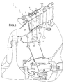
figure 1 représente une vue partielle en coupe d'une turbomachine selon un mode de réalisation préféré de la présente invention ; - la
figure 2 montre une vue partielle de face d'un assemblage de stator appartenant à la turbomachine montrée sur lafigure 1 , cet assemblage constituant une partie de stator ; - la
figure 2a représente une vue schématique partielle de dessus du premier ensemble annulaire appartenant à l'assemblage de stator montré sur lafigure 2 ; - la
figure 3 montre une vue en coupe selon la ligne III-III de lafigure 2 , sur laquelle il est représenté un dispositif d'assemblage selon un premier mode de réalisation préféré de la présente invention ; et - la
figure 4 montre une vue similaire à celle de lafigure 3 , sur laquelle le dispositif d'assemblage se présente sous la forme d'un second mode de réalisation préféré de la présente invention.
- the
figure 1 is a partial sectional view of a turbomachine according to a preferred embodiment of the present invention; - the
figure 2 shows a partial front view of a stator assembly belonging to the turbomachine shown on thefigure 1 this assembly constituting a part of a stator; - the
figure 2a represents a partial schematic view from above of the first annular assembly belonging to the stator assembly shown in FIG.figure 2 ; - the
figure 3 shows a sectional view along line III-III of thefigure 2 , on which there is shown an assembly device according to a first preferred embodiment of the present invention; and - the
figure 4 shows a view similar to that of thefigure 3 , on which the assembly device is in the form of a second preferred embodiment of the present invention.
En référence à la
Le module 2 comprend un stator partiellement composé par un assemblage 4 également objet de la présente invention, cet assemblage 4 comprenant globalement un premier ensemble 6 et un second ensemble 8 annulaires et concentriques selon un axe de turbomachine (non représenté), correspondant également à l'axe de ces ensembles 6, 8. Comme cela sera détaillé ci-après, les ensembles 6, 8 sont raccordés fixement l'un à l'autre par une pluralité de dispositifs d'assemblage 10 espacés circonférentiellement les uns des autres, de façon régulière, également dénommée « cyclique ».The module 2 comprises a stator partially composed by an
Comme visible sur la
Plus spécifiquement en référence à la
Il est noté que l'une des particularités des dispositifs d'assemblage 10 qui seront détaillés ultérieurement consiste à prévoir pour chacun d'eux une chape 22 disposant d'un angle de calage non nul par rapport à l'axe 20, cet angle de calage étant identique pour chacune des chapes 22 réalisées. En d'autres termes et en référence à la
Comme cela sera détaillé ultérieurement, la chape 22 d'un dispositif d'assemblage 10 est prévu pour recevoir entre ses deux oreilles l'extrémité radiale interne d'un organe de raccordement 28 prenant la forme d'un bras traversant l'espace annulaire 12, cet organe 28 disposant d'une extrémité radiale externe rapportée fixement sur le second ensemble 8, par exemple à l'aide de ferrures vissées.As will be detailed later, the
L'une des particularités de la présente invention consiste à offrir une conception autorisant une introduction simultanée de chacun des organes de raccordement 28 dans leur chape associée 22, par mise en regard des premier et second ensembles suivie de l'application d'un simple mouvement relatif de type hélicoïdal ou vissage selon l'axe 10. Pour ce faire, il est notamment prévu un fort écartement entre les oreilles 26a, 26b de la chape, comme cela va maintenant être décrit en référence à la
Sur cette figure montrant un dispositif 10 dans sa position assemblée, on peut apercevoir que l'organe de raccordement percé d'un orifice de passage 30 en extrémité radiale interne est logé entre une première oreille de chape 26a et une seconde oreille de chape 26b, disposant respectivement d'un premier orifice de chape 32a et d'un second orifice de chape 32b.In this figure showing a
De plus, le dispositif 10 comprend un système d'axe de cisaillement 34 traversant successivement le premier orifice de chape 32a, l'orifice de passage 30 et le second orifice de chape 32b. Globalement, ce système 34 comprend une vis 36 disposant d'une tête 38 munie de préférence d'un système de reprise de couple procurant une fonction anti-rotation pour le serrage du système d'écrou associé, et d'un fût 40 fileté à son extrémité libre. Le système 34 comprend également une douille de serrage 42 emmanchée dans le fût 40 et en appui contre la tête de vis 38. Enfin, le dispositif comprend également un système d'écrou 44 pouvant prendre la forme d'un simple écrou, vissé sur l'extrémité filetée 46 du fût de vis et en appui contre la face extérieure de la seconde oreille de chape 26b.In addition, the
Dans cette configuration, à l'opposé de l'extrémité filetée 46, la douille de serrage 42 du système d'axe 36 constitue une portion élargie traversant de part en part le premier orifice de chape 32a, impliquant notamment que la tête de vis 38 se situe extérieurement et à distance de la chape 22 contre laquelle elle ne vient pas en butée. A cet égard, on prévoit de préférence que le diamètre de la tête de vis 38 soit inférieur ou égal au diamètre extérieur de la douille, qui correspond quant à lui sensiblement au diamètre du premier orifice de chape 32a.In this configuration, opposite the threaded
Ainsi, la douille 42 formant portion élargie s'étend donc jusqu'à l'intérieur de l'espace inter-oreilles 48, pour constituer à son extrémité située dans cet espace 48 un épaulement 50 qui est donc lui aussi situé entre les première et seconde oreilles de chape 26a, 26b.Thus, the
Cet épaulement 50 vient en butée contre l'une des faces de l'organe de raccordement 28, l'autre de ses faces opposée à la première étant en appui contre une face intérieure de la seconde oreille 26b.This
Par conséquent, l'organe de raccordement 28 est maintenu fixement par pincement/frottement à distance de la première oreille 26a, grâce au plaquage réalisé par l'épaulement 50.Consequently, the connecting
A titre indicatif, il est préférentiellement prévu un diamètre sensiblement identique pour le fût de vis 40, le second orifice de chape 32b, et la surface intérieure de la douille de serrage 42, la diamètre de l'orifice de passage 30 pouvant quant à lui être légèrement supérieur afin de tolérer une incertitude de positionnement avant l'introduction du système d'axe 36 à travers l'orifice 30. Néanmoins, il est noté que le système d'axe 36 est de préférence prévu pour fonctionner essentiellement en cisaillement en coopération avec l'orifice de passage 30, et de façon secondaire en frottement par le contact entre les faces opposées de l'organe 28 et la face intérieure de l'oreille 26b ainsi que l'épaulement 50, respectivement.As an indication, it is preferentially provided a substantially identical diameter for the
Dans le cas représenté sur la
Naturellement, pour permettre l'assemblage par simple mouvement relatif hélicoïdal entre le premier ensemble 6 et le second ensemble 8 selon l'axe 20, l'homme du métier pourra adapter le rapport E/e entre l'écartement E entre les première et seconde oreilles de chape 26a, 26b selon une direction du système d'axe de cisaillement 36 confondue avec l'axe 52 des orifices de chape, et l'épaisseur e de l'organe de raccordement 28 selon la même direction 52. A titre d'exemple indicatif, ce rapport peut être tel qu'il remplisse la condition 1,3 < E/e < 2,5.Naturally, to allow the assembly by simple relative helical movement between the
En référence à présent à la
Ainsi, on peut s'apercevoir que la seule différence réside dans le fait de prévoir un système d'axe 36 d'un seul tenant, dont la tête 38 portant le fût de vis 40 est confondue avec la portion élargie 42 formant épaulement 50 et traversant le premier orifice de chape 32a. Ici encore, à l'état assemblé tel que représenté, il n'existe aucune butée entre la première oreille 26a et la tête de vis 38 la traversant.Thus, it can be seen that the only difference lies in the fact of providing an
Bien entendu, diverses modifications peuvent être apportées par l'homme du métier à l'invention qui vient d'être décrite, uniquement à titre d'exemples non limitatifs. A cet égard, il serait possible d'envisager d'implanter les chapes sur le second ensemble et les organes de raccordement sur le premier ensemble, sans sortir du cadre de l'invention.Of course, various modifications may be made by those skilled in the art to the invention which has just been described, solely by way of non-limiting examples. In this regard, it would be possible to consider placing the yokes on the second set and the connecting members on the first set, without departing from the scope of the invention.
Claims (14)
caractérisé en ce que ledit système d'axe (36) comprend, à l'opposé de l'extrémité filetée (46), une portion élargie (42) traversant ledit premier orifice de chape (32a) et formant un épaulement (50) situé entre lesdites première et seconde oreilles de chape (26a, 26b), ledit organe de raccordement (28) situé à distance de ladite première oreille de chape (26a) étant plaqué de part et d'autre respectivement contre ledit épaulement (50) et contre ladite seconde oreille de chape (26b).Assembly device (10) for two assemblies comprising a yoke (22) intended to be attached to a first assembly (6) and a connection member (28) intended to be attached to a second assembly (8), said member connection (28) pierced with a passage opening (30) being housed between a first and a second lug (26a, 26b) of said yoke respectively having a first clevis hole (32a) and a second orifice of clevis (32b), said apparatus further comprising a shear axis system (36) extending through each of said first clevis hole (32a), second clevis hole (32b) and through hole (30), and having one end threaded (46) cooperating with a nut system (44) bearing against said second clevis lug (26b),
characterized in that said spindle system (36) comprises, opposite the threaded end (46), an enlarged portion (42) extending through said first clevis hole (32a) and forming a shoulder (50) located between said first and second clevis ears (26a, 26b), said connecting member (28) spaced from said first clevis lug (26a) being pressed against said shoulder (50) on each side and against said second clevis ear (26b).
Applications Claiming Priority (1)
| Application Number | Priority Date | Filing Date | Title |
|---|---|---|---|
| FR0752894A FR2911933B1 (en) | 2007-01-26 | 2007-01-26 | DEVICE FOR ASSEMBLING TWO ASSEMBLIES, FOR EXAMPLE FOR TURBOMACHINE STATOR |
Publications (2)
| Publication Number | Publication Date |
|---|---|
| EP1950392A1 true EP1950392A1 (en) | 2008-07-30 |
| EP1950392B1 EP1950392B1 (en) | 2013-10-16 |
Family
ID=38456486
Family Applications (1)
| Application Number | Title | Priority Date | Filing Date |
|---|---|---|---|
| EP08100605.8A Active EP1950392B1 (en) | 2007-01-26 | 2008-01-17 | Device for assembling two units, for example for a turbomachine stator |
Country Status (7)
| Country | Link |
|---|---|
| US (1) | US7794203B2 (en) |
| EP (1) | EP1950392B1 (en) |
| JP (1) | JP5354915B2 (en) |
| CN (1) | CN101230874B (en) |
| CA (1) | CA2619416C (en) |
| FR (1) | FR2911933B1 (en) |
| RU (1) | RU2482304C2 (en) |
Cited By (2)
| Publication number | Priority date | Publication date | Assignee | Title |
|---|---|---|---|---|
| WO2016185361A1 (en) * | 2015-05-19 | 2016-11-24 | Turboden S.R.L. | Turbine for organic rankine cycles having improved centering between casing and shaft tube member |
| US9816387B2 (en) | 2014-09-09 | 2017-11-14 | United Technologies Corporation | Attachment faces for clamped turbine stator of a gas turbine engine |
Families Citing this family (15)
| Publication number | Priority date | Publication date | Assignee | Title |
|---|---|---|---|---|
| US8399618B2 (en) | 2004-10-21 | 2013-03-19 | Xencor, Inc. | Immunoglobulin insertions, deletions, and substitutions |
| US8883147B2 (en) | 2004-10-21 | 2014-11-11 | Xencor, Inc. | Immunoglobulins insertions, deletions, and substitutions |
| US20060134105A1 (en) * | 2004-10-21 | 2006-06-22 | Xencor, Inc. | IgG immunoglobulin variants with optimized effector function |
| FR2914017B1 (en) * | 2007-03-20 | 2011-07-08 | Snecma | SEALING DEVICE FOR A COOLING CIRCUIT, INTER-TURBINE HOUSING BEING EQUIPPED AND TURBOREACTOR COMPRISING THE SAME |
| US8757919B2 (en) * | 2008-08-29 | 2014-06-24 | Volvo Aero Corporation | Component and a gas turbine engine comprising the component |
| GB0905818D0 (en) | 2009-04-06 | 2009-05-20 | Airbus Uk Ltd | Coupling assembly |
| GB201120996D0 (en) * | 2011-12-07 | 2012-01-18 | Airbus Operations Ltd | Apparatus for attachment of wing panels |
| US9194296B2 (en) * | 2012-05-18 | 2015-11-24 | Pratt & Whitney Canada Corp. | Inner bypass duct wall attachment |
| US20140030069A1 (en) * | 2012-07-26 | 2014-01-30 | Jonathan D. Little | Top hat bearing retainer for variable vane actuator |
| US11000942B1 (en) * | 2017-02-02 | 2021-05-11 | Kraft Tool Company | Adjustable clamping tool clevis |
| CN106988794B (en) * | 2017-06-02 | 2018-12-14 | 中国航发南方工业有限公司 | Stator sub-assembly clamping means and stator sub-assembly |
| CN108608195B (en) * | 2018-08-10 | 2024-01-19 | 无锡铭方科技有限公司 | Bush press-fitting device |
| WO2022107332A1 (en) * | 2020-11-20 | 2022-05-27 | 本田技研工業株式会社 | Welding gun |
| CN112676824A (en) * | 2020-12-11 | 2021-04-20 | 中国北方发动机研究所(天津) | Centering tool for engine gear case and engine body |
| CN114833556B (en) * | 2021-08-31 | 2023-04-11 | 苏州朗科智能制造有限公司 | Spinning assembly replacer |
Citations (1)
| Publication number | Priority date | Publication date | Assignee | Title |
|---|---|---|---|---|
| US5848874A (en) * | 1997-05-13 | 1998-12-15 | United Technologies Corporation | Gas turbine stator vane assembly |
Family Cites Families (13)
| Publication number | Priority date | Publication date | Assignee | Title |
|---|---|---|---|---|
| US3710674A (en) * | 1970-12-18 | 1973-01-16 | Meteor Res Ltd | Expandable fastener |
| US4688378A (en) * | 1983-12-12 | 1987-08-25 | United Technologies Corporation | One piece band seal |
| US4684280A (en) * | 1986-04-14 | 1987-08-04 | Pneumo Abex Corporation | Clevis connection |
| US5024283A (en) * | 1990-02-06 | 1991-06-18 | Komatsu Dresser Company | Pivotable, resilient mounting |
| US5211536A (en) * | 1991-05-13 | 1993-05-18 | General Electric Company | Boltless turbine nozzle/stationary seal mounting |
| US5839878A (en) * | 1996-09-30 | 1998-11-24 | United Technologies Corporation | Gas turbine stator vane |
| JP4432137B2 (en) * | 1999-01-13 | 2010-03-17 | 株式会社Ihi | Turbine nozzle support device for gas turbine for jet engine |
| US6708482B2 (en) * | 2001-11-29 | 2004-03-23 | General Electric Company | Aircraft engine with inter-turbine engine frame |
| US6742987B2 (en) * | 2002-07-16 | 2004-06-01 | General Electric Company | Cradle mounted turbine nozzle |
| US7063505B2 (en) * | 2003-02-07 | 2006-06-20 | General Electric Company | Gas turbine engine frame having struts connected to rings with morse pins |
| FR2856755B1 (en) * | 2003-06-26 | 2007-03-23 | Snecma Moteurs | DEVICE FOR FASTENING BY SCREWS AND NUTS |
| US7101150B2 (en) * | 2004-05-11 | 2006-09-05 | Power Systems Mfg, Llc | Fastened vane assembly |
| US7951003B2 (en) * | 2004-06-14 | 2011-05-31 | Igt | Wireless identification and tracking in gaming systems |
-
2007
- 2007-01-26 FR FR0752894A patent/FR2911933B1/en active Active
-
2008
- 2008-01-17 EP EP08100605.8A patent/EP1950392B1/en active Active
- 2008-01-22 US US12/017,486 patent/US7794203B2/en active Active
- 2008-01-23 CA CA2619416A patent/CA2619416C/en active Active
- 2008-01-24 JP JP2008013417A patent/JP5354915B2/en active Active
- 2008-01-25 CN CN200810007046.0A patent/CN101230874B/en active Active
- 2008-01-25 RU RU2008103001/06A patent/RU2482304C2/en active
Patent Citations (1)
| Publication number | Priority date | Publication date | Assignee | Title |
|---|---|---|---|---|
| US5848874A (en) * | 1997-05-13 | 1998-12-15 | United Technologies Corporation | Gas turbine stator vane assembly |
Cited By (3)
| Publication number | Priority date | Publication date | Assignee | Title |
|---|---|---|---|---|
| US9816387B2 (en) | 2014-09-09 | 2017-11-14 | United Technologies Corporation | Attachment faces for clamped turbine stator of a gas turbine engine |
| US11041392B2 (en) | 2014-09-09 | 2021-06-22 | Raytheon Technologies Corporation | Attachment faces for clamped turbine stator of a gas turbine engine |
| WO2016185361A1 (en) * | 2015-05-19 | 2016-11-24 | Turboden S.R.L. | Turbine for organic rankine cycles having improved centering between casing and shaft tube member |
Also Published As
| Publication number | Publication date |
|---|---|
| JP2008215617A (en) | 2008-09-18 |
| CN101230874A (en) | 2008-07-30 |
| JP5354915B2 (en) | 2013-11-27 |
| EP1950392B1 (en) | 2013-10-16 |
| CA2619416C (en) | 2014-10-14 |
| FR2911933A1 (en) | 2008-08-01 |
| RU2482304C2 (en) | 2013-05-20 |
| CN101230874B (en) | 2014-11-19 |
| CA2619416A1 (en) | 2008-07-26 |
| RU2008103001A (en) | 2009-07-27 |
| US7794203B2 (en) | 2010-09-14 |
| US20080240845A1 (en) | 2008-10-02 |
| FR2911933B1 (en) | 2009-05-01 |
Similar Documents
| Publication | Publication Date | Title |
|---|---|---|
| EP1950392B1 (en) | Device for assembling two units, for example for a turbomachine stator | |
| EP1918512B1 (en) | Balancing system for a turbomachine rotor | |
| FR3014970A1 (en) | ASSEMBLY COMPRISING A JOINT AXLE SUPPORTED BY A CAP AND IMMOBILIZED IN TRANSLATION BY A BLOCKING DEVICE INCORPORATING A DOUBLE ANTI-ROTATION SYSTEM | |
| EP1342927B1 (en) | Device for attaching a component to an aircraft structure | |
| EP3146218B1 (en) | Ball-joint device for turbomachine | |
| EP2185826A2 (en) | Riveting screw tack and use thereof for temporarily fixing a boring grid to elements to be assembled | |
| EP1918511A2 (en) | Balancing system for a turbomachine rotor | |
| FR2970235A1 (en) | REMOVABLE DEVICE FOR PASSING CABLE IN CYCLE FRAME | |
| EP2978668A1 (en) | Ball-jointed device for suspending a turbomachine from a pylon or for suspending equipment from the body of the turbomachine | |
| FR3052828A1 (en) | ROD OF ADJUSTABLE LENGTH FOR TURBOMACHINE | |
| EP2003384A1 (en) | Connection system comprising safety attachment means | |
| EP3623647A1 (en) | Linking device with double shearing provided with an off-centre axis and off-centre sleeves, mechanical assembly comprising such a device and assembly method | |
| FR2949138A1 (en) | Turbomachine e.g. turbopropeller, for airplane, has snap ring cooperating with anti-rotation collar by axial abutment, where collar has grooves co-operating with complementary grooves of nut and ring to immobilize rotation of collar | |
| FR2944332A1 (en) | Sealing joint assembly for use on support in aeronautical industry for fixing sealing joints of e.g. aerofoil, on aircraft, has intermediate part comprising through hole and blocking unit for blocking rotation of head of screw | |
| FR2665741A1 (en) | DELIVERY AND / OR SUCTION VALVE, ESPECIALLY FOR PISTON COMPRESSOR (S). | |
| FR2799515A1 (en) | GAME RETRIEVAL SYSTEM FOR ATTACHING TWO PIECES TO EACH OTHER USING A SCREW TYPE FASTENER | |
| BE1012055A3 (en) | Device for fixing nut. | |
| FR3091911A1 (en) | Device for pivoting connection between at least two parts, aircraft comprising a cover equipped with said pivoting connection device | |
| FR2903466A1 (en) | Floating nut system for aircraft, has locking effort taking ring that traverses screw passage hole for projecting face of main plate opposite to another face of main plate, and floating nut supported against ring | |
| FR3026151A1 (en) | BARROW NUT ASSEMBLY, AIRCRAFT STRUCTURAL ASSEMBLY COMPRISING SUCH A DEVICE, AND CORRESPONDING ASSEMBLY METHOD | |
| FR2991113A1 (en) | Support device assembly for supporting electric strands on fuselage panel of plane, has concave surface, where one support device is arranged at distance equal to or higher than predetermined minimal distance of strands | |
| FR2958265A1 (en) | Connection assembly for engine pylon under aerofoil of aircraft, has locking assembly assembled around lag bolt at free end of crossing axle system to block axle system in translation, and secondary axle assembled in external axle | |
| FR2900705A1 (en) | CLUTCH THRUST BEARING | |
| FR2981139A1 (en) | Fixation device for fixing actuator on mirror through interface for deforming part for correction of wave surface of e.g. laser beam, has locking unit ensuring maintenance of male and female elements or release of elements for separation | |
| FR2958263A1 (en) | Connection assembly for engine nacelle stub utilized to fix engine under aerofoil of aircraft, has pin sliding inside interior secondary axle along L-shaped cross-piece for driving displacement of L-shaped foot before fitting aerofoil |
Legal Events
| Date | Code | Title | Description |
|---|---|---|---|
| PUAI | Public reference made under article 153(3) epc to a published international application that has entered the european phase |
Free format text: ORIGINAL CODE: 0009012 |
|
| AK | Designated contracting states |
Kind code of ref document: A1 Designated state(s): AT BE BG CH CY CZ DE DK EE ES FI FR GB GR HR HU IE IS IT LI LT LU LV MC MT NL NO PL PT RO SE SI SK TR |
|
| AX | Request for extension of the european patent |
Extension state: AL BA MK RS |
|
| 17P | Request for examination filed |
Effective date: 20080929 |
|
| AKX | Designation fees paid |
Designated state(s): DE FR GB IT |
|
| 17Q | First examination report despatched |
Effective date: 20090630 |
|
| GRAP | Despatch of communication of intention to grant a patent |
Free format text: ORIGINAL CODE: EPIDOSNIGR1 |
|
| INTG | Intention to grant announced |
Effective date: 20130523 |
|
| GRAS | Grant fee paid |
Free format text: ORIGINAL CODE: EPIDOSNIGR3 |
|
| GRAA | (expected) grant |
Free format text: ORIGINAL CODE: 0009210 |
|
| AK | Designated contracting states |
Kind code of ref document: B1 Designated state(s): DE FR GB IT |
|
| REG | Reference to a national code |
Ref country code: GB Ref legal event code: FG4D Free format text: NOT ENGLISH |
|
| REG | Reference to a national code |
Ref country code: DE Ref legal event code: R096 Ref document number: 602008028079 Country of ref document: DE Effective date: 20131212 |
|
| REG | Reference to a national code |
Ref country code: DE Ref legal event code: R097 Ref document number: 602008028079 Country of ref document: DE |
|
| PLBE | No opposition filed within time limit |
Free format text: ORIGINAL CODE: 0009261 |
|
| STAA | Information on the status of an ep patent application or granted ep patent |
Free format text: STATUS: NO OPPOSITION FILED WITHIN TIME LIMIT |
|
| 26N | No opposition filed |
Effective date: 20140717 |
|
| REG | Reference to a national code |
Ref country code: DE Ref legal event code: R097 Ref document number: 602008028079 Country of ref document: DE Effective date: 20140717 |
|
| REG | Reference to a national code |
Ref country code: FR Ref legal event code: PLFP Year of fee payment: 9 |
|
| REG | Reference to a national code |
Ref country code: FR Ref legal event code: PLFP Year of fee payment: 10 |
|
| REG | Reference to a national code |
Ref country code: FR Ref legal event code: PLFP Year of fee payment: 11 |
|
| REG | Reference to a national code |
Ref country code: FR Ref legal event code: CD Owner name: SAFRAN AIRCRAFT ENGINES, FR Effective date: 20170717 |
|
| PGFP | Annual fee paid to national office [announced via postgrant information from national office to epo] |
Ref country code: IT Payment date: 20230103 Year of fee payment: 16 Ref country code: DE Payment date: 20221220 Year of fee payment: 16 |
|
| PGFP | Annual fee paid to national office [announced via postgrant information from national office to epo] |
Ref country code: GB Payment date: 20231219 Year of fee payment: 17 |
|
| PGFP | Annual fee paid to national office [announced via postgrant information from national office to epo] |
Ref country code: FR Payment date: 20231219 Year of fee payment: 17 |