EP1950366B1 - Türgriff mit Sicherheitsvorrichtung für eine Kraftfahrzeugtür - Google Patents
Türgriff mit Sicherheitsvorrichtung für eine Kraftfahrzeugtür Download PDFInfo
- Publication number
- EP1950366B1 EP1950366B1 EP07116051A EP07116051A EP1950366B1 EP 1950366 B1 EP1950366 B1 EP 1950366B1 EP 07116051 A EP07116051 A EP 07116051A EP 07116051 A EP07116051 A EP 07116051A EP 1950366 B1 EP1950366 B1 EP 1950366B1
- Authority
- EP
- European Patent Office
- Prior art keywords
- grip
- lever
- configuration
- handle group
- control lever
- Prior art date
- Legal status (The legal status is an assumption and is not a legal conclusion. Google has not performed a legal analysis and makes no representation as to the accuracy of the status listed.)
- Active
Links
- 230000008878 coupling Effects 0.000 claims abstract description 25
- 238000010168 coupling process Methods 0.000 claims abstract description 25
- 238000005859 coupling reaction Methods 0.000 claims abstract description 25
- 238000010276 construction Methods 0.000 description 2
- 238000004519 manufacturing process Methods 0.000 description 2
- 230000001419 dependent effect Effects 0.000 description 1
- 230000000694 effects Effects 0.000 description 1
Images


Classifications
-
- E—FIXED CONSTRUCTIONS
- E05—LOCKS; KEYS; WINDOW OR DOOR FITTINGS; SAFES
- E05B—LOCKS; ACCESSORIES THEREFOR; HANDCUFFS
- E05B85/00—Details of vehicle locks not provided for in groups E05B77/00 - E05B83/00
- E05B85/10—Handles
- E05B85/14—Handles pivoted about an axis parallel to the wing
- E05B85/16—Handles pivoted about an axis parallel to the wing a longitudinal grip part being pivoted at one end about an axis perpendicular to the longitudinal axis of the grip part
-
- E—FIXED CONSTRUCTIONS
- E05—LOCKS; KEYS; WINDOW OR DOOR FITTINGS; SAFES
- E05B—LOCKS; ACCESSORIES THEREFOR; HANDCUFFS
- E05B77/00—Vehicle locks characterised by special functions or purposes
- E05B77/02—Vehicle locks characterised by special functions or purposes for accident situations
- E05B77/04—Preventing unwanted lock actuation, e.g. unlatching, at the moment of collision
-
- E—FIXED CONSTRUCTIONS
- E05—LOCKS; KEYS; WINDOW OR DOOR FITTINGS; SAFES
- E05B—LOCKS; ACCESSORIES THEREFOR; HANDCUFFS
- E05B13/00—Devices preventing the key or the handle or both from being used
- E05B13/005—Disconnecting the handle
Definitions
- the present invention relates to a handle group for a motor vehicle door provided with a safety device suitable for preventing the door opening in a collision.
- the object of the present invention is to make a handle group for a motor vehicle door provided with a safety device which should overcome the disadvantages mentioned above with reference to the prior art.
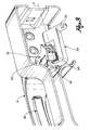
- FIG. 1 shows a view of the handle group according to the present invention, in a rest configuration.
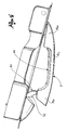
- figure 2 shows a safety device of the handle group of figure 1 in the rest configuration
- figure 3 shows the safety device of figure 2 in an engaged configuration and with handle at rest;
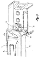
- FIG. 4 shows the handle group in a configuration with pulled handle
- - figure 5 shows the safety device in the engaged configuration and with pulled handle.
- reference numeral 1 globally denotes a handle group for a motor vehicle door.
- the handle group 1 is associable to a closing mechanism suitable for switching from a closed configuration, wherein it constrains the door to the frame of the motor vehicle for preventing the opening thereof, to an open configuration, wherein the door opening is allowed.
- the handle group comprises a grip 2 suitable for being grasped by a user and being moved from a rest configuration to a pulled configuration for allowing the door opening.
- grip 2 comprises a hinging portion 4, usually arranged into the door, suitable for hinging the grip to a fixed bar 6, inside the door as well.
- grip 2 comprises a handle 8, arranged on the outer surface of the door and connected to the hinging portion 2.
- handle 8 comprises a first enlargement 8a, on the end of the hinging portion 4, a second enlargement 8b, on the opposite side, and a thinned portion 8c, which connects enlargements 8a, 8b and with the outer surface of the door forms a gripping space 10 suitable for the introduction of a hand of the user.
- grip 2 exhibits a window 8d, for example obtained on the back surface of grip 2, in particular on the back surface of the thinned portion 8c, facing the door surface.
- the handle group 1 comprises a control lever 20 associable to the closing mechanism for controlling it from the closed configuration to the open configuration.
- control lever 20 is connectable to the closing mechanism by a cable (not shown), known in the field as "Bowden cable", or by a tie rod.
- the control lever 20 is hinged to a support along an axis of rotation Z, so as to be moved and in particular rotated from a rest position, wherein it does not influence the closing mechanism, to an active position wherein it influences the closing mechanism in opening.
- the handle group comprises elastic means suitable for constantly influencing the control lever 20 so as to oppose the passage of the control lever from the rest position to the active position.
- the elastic means comprise a spring 22, arranged about the axis of rotation Z of the control lever 20.
- control lever 20 comprises a hook portion 24 for the engagement with grip 2 and a pulling portion 26 for the connection to the closing mechanism.
- the pulling portion 26 is associated to the Bowden cable or the tie rod.
- the hook portion 24 is angularly spaced relative to the pulling portion 26, for facilitating the connection of the Bowden cable to the closing mechanism and not undergoing structural interferences between the Bowden cable and the control lever, especially ion the active position thereof.
- the hook portion 24 is proximal to the axis of rotation Z and the pulling portion 26 is distal to the axis of rotation Z, for obtaining a lever effect that facilitates the actuation of the closing mechanism in opening also in case of a weak action on the grip.
- the handle group 1 comprises a coupling lever 30 integral with grip 2, suitable for switching from a disengaged configuration to an engaged configuration wherein it engages the control lever 20, thus allowing the control of the closing mechanism in opening moving grip 2.
- Said lever normally in the disengaged configuration, is influenced to stay in said configuration by elastic means (not shown).
- the coupling lever 30 comprises a lever body 32, partly seated in grip 2, for example in the second enlargement 8b thereof, and a projection 34, protruding from the lever body 32, suitable for engaging the coupling portion 24 of the control lever 20.
- the coupling lever 30 exhibits a hammer shape.
- the coupling lever 30 is actuable by the user from outside the motor vehicle, preferably at the same time as the grasping of the grip, for switching from the disengaged configuration to the engaged configuration wherein it engages the control lever 20.
- the handle group 1 comprises a safety lever 40, arranged inside grip 2 and accessible by the user through window 8d obtained in grip 2.
- the safety lever 40 is operatively engageable with the coupling lever 30 so that moving the safety lever 40, the coupling lever 30 switches from the disengaged configuration to the engaged configuration with the control lever 20.
- the safety lever 40 protrudes from window 8d of grip 2, to be pressed by the user's hand that grasps grip 2, at the same time as grasping grip 2.
- the handle group comprises a multiplier device (not shown) arranged along the kinematic chain between the safety lever 40 and the coupling lever 30, suitable for multiplying the movement of the safety lever 40, that is, such as to match a slight movement of the safety lever with a movement of the coupling lever 30 sufficiently wide to engage the control lever 20.
- a multiplier device (not shown) arranged along the kinematic chain between the safety lever 40 and the coupling lever 30, suitable for multiplying the movement of the safety lever 40, that is, such as to match a slight movement of the safety lever with a movement of the coupling lever 30 sufficiently wide to engage the control lever 20.
- the grip is in the rest configuration, that is, is not pulled by the user
- the safety lever 40 is not pressed by the user, widely protrudes from window 8d of grip 2 and does not influence the coupling lever 30 towards the engagement configuration thereof;
- the coupling lever 30 is in the disengaged configuration, that is, it does not engage the control lever 20;
- control lever 20 is in the rest position, that is, it does not influence the closing mechanism to open;
- the closing mechanism is in the closed configuration, that is, it engages the vehicle frame, so as to prevent the door opening.
- the grip is in the rest configuration, that is, is not pulled by the user
- the safety lever 40 is pressed by the user and influences the coupling lever 30 towards the engagement configuration thereof with the control lever 20;
- the coupling lever 30 is in the engaged configuration, that is, it engages the control lever 20;
- control lever 20 is in the rest position, that is, it does not influence the closing mechanism to open;
- the closing mechanism is in the closed configuration, that is, it engages the vehicle frame, so as to prevent the door opening.
- the grip is in the pulled configuration, that is, is pulled by the user;
- the safety lever 40 is pressed by the user and influences the coupling lever 30 towards the engagement configuration thereof with the control lever 20;
- the coupling lever 30 is in the engaged configuration, that is, it engages the control lever 20;
- control lever 20 is in the active position, that is, it influences the closing mechanism to open;
- the closing mechanism is in the open configuration, that is, it does not engage the vehicle frame, so as to allow the door opening.
- the closing mechanism disengages the vehicle frame and the door opening is allowed.
- control lever is hinged to the support body so as to be turnable about the axis of rotation Z, that the axils of rotation lays on a horizontal plane and that the movement of the grip from the rest configuration to the pulled configuration takes place on a plane coplanar to said horizontal plane.
- the handle group according to the present invention allows preventing undesired door opening subsequent to collisions, overcoming the disadvantages mentioned with reference to the prior art, since it does not exhibit inertial masses and is structurally simple in the construction and assembly thereof.
- the handle group is convenient to use since the actuation of the safety lever occurs at the same time as the grip grasping.
- the construction is optimised to reduce the user's effort required to actuate the safety lever and to release the closing mechanism.
Landscapes
- Lock And Its Accessories (AREA)
- Steering Devices For Bicycles And Motorcycles (AREA)
Claims (10)
- Griff- bzw. Türgriffgruppe bzw. -anordnung (1) für eine Kraftfahrzeugtür, die mit einem Schließmechanismus verbindbar ist, der geeignet ist, aus einer geschlossenen Konfiguration, in der er die Tür an den Rahmen des Kraftfahr-zeugs drängt, um deren Öffnen zu verhindern, in eine geöffnete Konfiguration zu wechseln,
wobei die Türgriffanordnung umfasst- einen Griff bzw. Handgriff (2), der geeignet ist, von einer Bedienperson ge-griffen und aus einer Ruhekonfiguration in eine gezogene Konfiguration bewegt zu werden, um das Öffnen der Tür zu erlauben;- einen Kontroll- bzw. Bedienhebel (20), der mit dem Schließmechanismus verbindbar ist, um ihn aus der geschlossenen Konfiguration in die geöffnete Konfiguration zu bringen;wobei die Türgriffanordnung dadurch gekennzeichnet ist, dass der Handgriff in der Ruhekonfiguration von dem Kontrollhebel außer Eingriff gebracht ist, und wobei die Türgriffanordnung einen Kopplungshebel (30) einstückig bzw. integ-ral mit dem Handgriff umfasst, der von der Bedienperson betätigbar ist und geeignet ist, bei Betätigung aus einer Außereingriffskonfiguration in eine Ein-griffskonfiguration zu wechseln, in der er mit dem Kontrollhebel (20) in Eingriff kommt, was die Kontrolle des Schließmechanismus beim Öffnen auf Grund der Bewegung des Handgriffs erlaubt. - Türgriffanordnung nach Anspruch 1, umfassend einen Sicherheitshebel (40), der in dem Handgriff angeordnet und von der Bedienperson durch ein in dem Handgriff enthaltenes Fenster (8d) zugänglich ist, der wirkungsmäßig bzw. be-triebsmäßig mit dem Kopplungshebel in Eingriff ist, so dass beim Bewegen des Sicherheitshebels der Kopplungshebel aus der Außereingriffskonfiguration in die Eingriffskonfiguration mit dem Kontrollhebel wechselt.
- Türgriffanordnung nach Anspruch 2, wobei der Sicherheitshebel von bzw. aus dem Fenster des Handgriffs vorsteht, um von der Hand der Bedienperson ge-drückt zu werden, die den Handgriff greift.
- Türgriffanordnung nach Anspruch 3, wobei das Fenster an der hinteren Fläche bzw. Oberfläche des Handgriffs der Türfläche bzw. -oberfläche zugewandt enthalten ist.
- Türgriffanordnung nach einem der vorhergehenden Ansprüche, wobei
der Kontrollhebel geeignet ist, gelenkig mit einem Stütz- bzw. Trägerkörper verbunden zu sein, um um eine Drehachse (Z) drehbar zu sein, und wobei
die Drehachse auf einer Ebene liegt, und wobei
die Handgriffbewegung aus der Ruhekonfiguration in die gezogene Konfigura-tion auf einer Ebene stattfindet, die koplanar zu der Ebene der Drehachse ist. - Türgriffanordnung nach Anspruch 5, umfassend elastische Mittel (22), die ge-eignet sind, den Kontrollhebel konstant bzw. dauerhaft zu beeinflussen, um der Wirkung bzw. Aktion entgegenzuwirken, die von der Bedienperson auf den Handgriff in der Eingriffskonfiguration mit dem Kopplungshebel und mit gezo-genem Türgriff zum Öffnen der Tür ausgeübt wird.
- Türgriffanordnung nach Anspruch 5 oder 6, wobei der Kontrollhebel einen Ha-kenabschnitt (24) zum Eingriff mit dem Kopplungshebel (30) und einen Zieh-abschnitt (26) zur Verbindung mit dem Schließmechanismus umfasst.
- Türgriffanordnung nach Anspruch 7, wobei der Hakenabschnitt winkelig relativ zu dem Ziehabschnitt beabstandet ist.
- Türgriffanordnung nach Anspruch 7 oder 8, wobei der Hakenabschnitt proxi-mal zu der Drehachse ist und der Ziehabschnitt distal zu der Drehachse ist.
- Türgriffanordnung nach einem der vorhergehenden Ansprüche, wobei der Kopplungshebel (30) einen Hebelkörper (32), der teilweise in dem Handgriff (2) platziert ist, und einen Vorsprung (34) umfasst, der von bzw. aus dem He-belkörper (32) vorsteht und geeignet ist, in den Kontrollhebel (20) einzugrei-fen.
Applications Claiming Priority (1)
| Application Number | Priority Date | Filing Date | Title |
|---|---|---|---|
| IT000009A ITBS20070009A1 (it) | 2007-01-29 | 2007-01-29 | Gruppo maniglia per sportello di autoveicolo munito di dispositivo di sicurezza |
Publications (3)
| Publication Number | Publication Date |
|---|---|
| EP1950366A2 EP1950366A2 (de) | 2008-07-30 |
| EP1950366A3 EP1950366A3 (de) | 2009-05-06 |
| EP1950366B1 true EP1950366B1 (de) | 2010-01-13 |
Family
ID=38566900
Family Applications (1)
| Application Number | Title | Priority Date | Filing Date |
|---|---|---|---|
| EP07116051A Active EP1950366B1 (de) | 2007-01-29 | 2007-09-10 | Türgriff mit Sicherheitsvorrichtung für eine Kraftfahrzeugtür |
Country Status (4)
| Country | Link |
|---|---|
| EP (1) | EP1950366B1 (de) |
| AT (1) | ATE455222T1 (de) |
| DE (1) | DE602007004294D1 (de) |
| IT (1) | ITBS20070009A1 (de) |
Cited By (3)
| Publication number | Priority date | Publication date | Assignee | Title |
|---|---|---|---|---|
| US20140015263A1 (en) * | 2012-07-11 | 2014-01-16 | Huf North America Automotive Parts Mfg. Corp. | Vehicular Door Handle Assembly With Electrically Deployable Latch Connection |
| US9341005B2 (en) | 2009-10-20 | 2016-05-17 | Huf Hulsbeck & Furst Gmbh & Co. | Handle device |
| US9404292B2 (en) | 2012-07-11 | 2016-08-02 | Huf North America Automotive Parts Mfg. Corp. | Vehicular door handle assembly with deployable latch connection |
Families Citing this family (6)
| Publication number | Priority date | Publication date | Assignee | Title |
|---|---|---|---|---|
| DE202009010681U1 (de) * | 2009-08-07 | 2009-12-17 | Huf Hülsbeck & Fürst Gmbh & Co. Kg | Öffnungs- und/oder Schließmechanismus an Türen, Klappen odg., insbesondere an Fahrzeugen |
| DE102009056921A1 (de) | 2009-12-03 | 2011-06-09 | GM Global Technology Operations LLC, ( n. d. Ges. d. Staates Delaware ), Detroit | Griffmodul für eine Kraftfahrzeugtür |
| IT1397430B1 (it) | 2009-12-11 | 2013-01-10 | Illinois Tool Works | Gruppo maniglia per una porta di veicolo. |
| WO2011077222A2 (en) | 2009-12-21 | 2011-06-30 | Illinois Tool Works Inc. | Vehicle door safety lock handle assembly |
| IT1399688B1 (it) * | 2010-03-30 | 2013-04-26 | Illinois Tool Works | Gruppo maniglia con bloccaggio di sicurezza per una porta di veicolo |
| ITMI20100723A1 (it) | 2010-04-27 | 2011-10-27 | Valeo Spa | Maniglia per sportello di veicolo comprendente un dispositivo di sicurezza |
Family Cites Families (4)
| Publication number | Priority date | Publication date | Assignee | Title |
|---|---|---|---|---|
| DE3500550A1 (de) * | 1985-01-10 | 1985-10-31 | Daimler-Benz Ag, 7000 Stuttgart | Schlosssystem in einem kraftfahrzeug-tuerverschluss |
| EP1658411B1 (de) * | 2003-08-27 | 2007-11-21 | Key Plastics LLC | Griffanordnung mit doppelverriegelungsmerkmal |
| FR2869059B1 (fr) * | 2004-04-14 | 2006-06-30 | Fabi Automobile Soc Par Action | Mecanisme d'ouverture/fermeture de portiere de vehicule automobile |
| WO2006112916A1 (en) * | 2005-02-08 | 2006-10-26 | Adac Plastics, Inc. | Vehicular door handle including secondary latch |
-
2007
- 2007-01-29 IT IT000009A patent/ITBS20070009A1/it unknown
- 2007-09-10 DE DE602007004294T patent/DE602007004294D1/de active Active
- 2007-09-10 EP EP07116051A patent/EP1950366B1/de active Active
- 2007-09-10 AT AT07116051T patent/ATE455222T1/de not_active IP Right Cessation
Cited By (4)
| Publication number | Priority date | Publication date | Assignee | Title |
|---|---|---|---|---|
| US9341005B2 (en) | 2009-10-20 | 2016-05-17 | Huf Hulsbeck & Furst Gmbh & Co. | Handle device |
| US20140015263A1 (en) * | 2012-07-11 | 2014-01-16 | Huf North America Automotive Parts Mfg. Corp. | Vehicular Door Handle Assembly With Electrically Deployable Latch Connection |
| US9394729B2 (en) | 2012-07-11 | 2016-07-19 | Huf North America Automotive Parts Mfg. Corp. | Vehicular door handle assembly with electrically deployable latch connection |
| US9404292B2 (en) | 2012-07-11 | 2016-08-02 | Huf North America Automotive Parts Mfg. Corp. | Vehicular door handle assembly with deployable latch connection |
Also Published As
| Publication number | Publication date |
|---|---|
| EP1950366A3 (de) | 2009-05-06 |
| ITBS20070009A1 (it) | 2008-07-30 |
| DE602007004294D1 (de) | 2010-03-04 |
| EP1950366A2 (de) | 2008-07-30 |
| ATE455222T1 (de) | 2010-01-15 |
Similar Documents
| Publication | Publication Date | Title |
|---|---|---|
| EP1950366B1 (de) | Türgriff mit Sicherheitsvorrichtung für eine Kraftfahrzeugtür | |
| CN106489015B (zh) | 机动车锁装置 | |
| US8342583B2 (en) | Vehicle panel control system | |
| JP5852113B2 (ja) | 車両における把持部を備える開閉式ハンドル | |
| EP3274532B1 (de) | Einziehbare griffanordnung | |
| US5232253A (en) | Power-closing lock device for vehicle door | |
| KR101673685B1 (ko) | 자동차용 도어 래치 어셈블리 | |
| US12129691B2 (en) | Emergency access device for a vehicle opening panel with rotary deployment arm | |
| CN113574241B (zh) | 用于机动车门元件的开启设备 | |
| KR20180118772A (ko) | 자동차의 도어 또는 플랩을 열기 위한 장치 | |
| CN111356817A (zh) | 用于机动车门的开启设备 | |
| JP2019078160A (ja) | 自動車のためのアウタードアハンドル機構 | |
| US9638299B2 (en) | Actuating device | |
| KR20130006348A (ko) | 안전 도어 핸들 유닛 | |
| CN110741129A (zh) | 用于机动车的门把手设备 | |
| US11572721B2 (en) | Latch assembly | |
| JPH07501769A (ja) | 可動式グローブコンパートメント | |
| RU2015113726A (ru) | Дверной замок транспортного средства | |
| CN113195858B (zh) | 用于机动车门元件的开启设备 | |
| EP3587715B1 (de) | Verfahren und system zum entriegeln einer fahrzeughaube | |
| DE502006004027D1 (de) | Bowdenzuganbindung mit integrierter massensperre | |
| KR20140075371A (ko) | 슬라이딩 도어용 아웃사이드 핸들 | |
| US12110718B2 (en) | Motor vehicle lock | |
| CA2471315A1 (en) | Lock for lever-handled door latch | |
| JP4042954B2 (ja) | 車両における開閉リッドロック装置 |
Legal Events
| Date | Code | Title | Description |
|---|---|---|---|
| PUAI | Public reference made under article 153(3) epc to a published international application that has entered the european phase |
Free format text: ORIGINAL CODE: 0009012 |
|
| AK | Designated contracting states |
Kind code of ref document: A2 Designated state(s): AT BE BG CH CY CZ DE DK EE ES FI FR GB GR HU IE IS IT LI LT LU LV MC MT NL PL PT RO SE SI SK TR |
|
| AX | Request for extension of the european patent |
Extension state: AL BA HR MK RS |
|
| PUAL | Search report despatched |
Free format text: ORIGINAL CODE: 0009013 |
|
| AK | Designated contracting states |
Kind code of ref document: A3 Designated state(s): AT BE BG CH CY CZ DE DK EE ES FI FR GB GR HU IE IS IT LI LT LU LV MC MT NL PL PT RO SE SI SK TR |
|
| AX | Request for extension of the european patent |
Extension state: AL BA HR MK RS |
|
| 17P | Request for examination filed |
Effective date: 20090508 |
|
| 17Q | First examination report despatched |
Effective date: 20090605 |
|
| GRAP | Despatch of communication of intention to grant a patent |
Free format text: ORIGINAL CODE: EPIDOSNIGR1 |
|
| GRAS | Grant fee paid |
Free format text: ORIGINAL CODE: EPIDOSNIGR3 |
|
| GRAA | (expected) grant |
Free format text: ORIGINAL CODE: 0009210 |
|
| AK | Designated contracting states |
Kind code of ref document: B1 Designated state(s): AT BE BG CH CY CZ DE DK EE ES FI FR GB GR HU IE IS IT LI LT LU LV MC MT NL PL PT RO SE SI SK TR |
|
| AX | Request for extension of the european patent |
Extension state: AL BA HR MK RS |
|
| REG | Reference to a national code |
Ref country code: GB Ref legal event code: FG4D |
|
| REG | Reference to a national code |
Ref country code: CH Ref legal event code: EP |
|
| REG | Reference to a national code |
Ref country code: IE Ref legal event code: FG4D |
|
| REF | Corresponds to: |
Ref document number: 602007004294 Country of ref document: DE Date of ref document: 20100304 Kind code of ref document: P |
|
| REG | Reference to a national code |
Ref country code: NL Ref legal event code: VDEP Effective date: 20100113 |
|
| LTIE | Lt: invalidation of european patent or patent extension |
Effective date: 20100113 |
|
| PG25 | Lapsed in a contracting state [announced via postgrant information from national office to epo] |
Ref country code: AT Free format text: LAPSE BECAUSE OF FAILURE TO SUBMIT A TRANSLATION OF THE DESCRIPTION OR TO PAY THE FEE WITHIN THE PRESCRIBED TIME-LIMIT Effective date: 20100113 |
|
| PG25 | Lapsed in a contracting state [announced via postgrant information from national office to epo] |
Ref country code: PT Free format text: LAPSE BECAUSE OF FAILURE TO SUBMIT A TRANSLATION OF THE DESCRIPTION OR TO PAY THE FEE WITHIN THE PRESCRIBED TIME-LIMIT Effective date: 20100513 Ref country code: LT Free format text: LAPSE BECAUSE OF FAILURE TO SUBMIT A TRANSLATION OF THE DESCRIPTION OR TO PAY THE FEE WITHIN THE PRESCRIBED TIME-LIMIT Effective date: 20100113 Ref country code: NL Free format text: LAPSE BECAUSE OF FAILURE TO SUBMIT A TRANSLATION OF THE DESCRIPTION OR TO PAY THE FEE WITHIN THE PRESCRIBED TIME-LIMIT Effective date: 20100113 Ref country code: ES Free format text: LAPSE BECAUSE OF FAILURE TO SUBMIT A TRANSLATION OF THE DESCRIPTION OR TO PAY THE FEE WITHIN THE PRESCRIBED TIME-LIMIT Effective date: 20100424 Ref country code: IS Free format text: LAPSE BECAUSE OF FAILURE TO SUBMIT A TRANSLATION OF THE DESCRIPTION OR TO PAY THE FEE WITHIN THE PRESCRIBED TIME-LIMIT Effective date: 20100513 |
|
| PG25 | Lapsed in a contracting state [announced via postgrant information from national office to epo] |
Ref country code: LV Free format text: LAPSE BECAUSE OF FAILURE TO SUBMIT A TRANSLATION OF THE DESCRIPTION OR TO PAY THE FEE WITHIN THE PRESCRIBED TIME-LIMIT Effective date: 20100113 Ref country code: SI Free format text: LAPSE BECAUSE OF FAILURE TO SUBMIT A TRANSLATION OF THE DESCRIPTION OR TO PAY THE FEE WITHIN THE PRESCRIBED TIME-LIMIT Effective date: 20100113 Ref country code: PL Free format text: LAPSE BECAUSE OF FAILURE TO SUBMIT A TRANSLATION OF THE DESCRIPTION OR TO PAY THE FEE WITHIN THE PRESCRIBED TIME-LIMIT Effective date: 20100113 Ref country code: FI Free format text: LAPSE BECAUSE OF FAILURE TO SUBMIT A TRANSLATION OF THE DESCRIPTION OR TO PAY THE FEE WITHIN THE PRESCRIBED TIME-LIMIT Effective date: 20100113 |
|
| PG25 | Lapsed in a contracting state [announced via postgrant information from national office to epo] |
Ref country code: CY Free format text: LAPSE BECAUSE OF FAILURE TO SUBMIT A TRANSLATION OF THE DESCRIPTION OR TO PAY THE FEE WITHIN THE PRESCRIBED TIME-LIMIT Effective date: 20100113 Ref country code: SE Free format text: LAPSE BECAUSE OF FAILURE TO SUBMIT A TRANSLATION OF THE DESCRIPTION OR TO PAY THE FEE WITHIN THE PRESCRIBED TIME-LIMIT Effective date: 20100113 Ref country code: RO Free format text: LAPSE BECAUSE OF FAILURE TO SUBMIT A TRANSLATION OF THE DESCRIPTION OR TO PAY THE FEE WITHIN THE PRESCRIBED TIME-LIMIT Effective date: 20100113 Ref country code: GR Free format text: LAPSE BECAUSE OF FAILURE TO SUBMIT A TRANSLATION OF THE DESCRIPTION OR TO PAY THE FEE WITHIN THE PRESCRIBED TIME-LIMIT Effective date: 20100414 Ref country code: EE Free format text: LAPSE BECAUSE OF FAILURE TO SUBMIT A TRANSLATION OF THE DESCRIPTION OR TO PAY THE FEE WITHIN THE PRESCRIBED TIME-LIMIT Effective date: 20100113 Ref country code: BE Free format text: LAPSE BECAUSE OF FAILURE TO SUBMIT A TRANSLATION OF THE DESCRIPTION OR TO PAY THE FEE WITHIN THE PRESCRIBED TIME-LIMIT Effective date: 20100113 |
|
| PLBE | No opposition filed within time limit |
Free format text: ORIGINAL CODE: 0009261 |
|
| STAA | Information on the status of an ep patent application or granted ep patent |
Free format text: STATUS: NO OPPOSITION FILED WITHIN TIME LIMIT |
|
| PG25 | Lapsed in a contracting state [announced via postgrant information from national office to epo] |
Ref country code: SK Free format text: LAPSE BECAUSE OF FAILURE TO SUBMIT A TRANSLATION OF THE DESCRIPTION OR TO PAY THE FEE WITHIN THE PRESCRIBED TIME-LIMIT Effective date: 20100113 Ref country code: CZ Free format text: LAPSE BECAUSE OF FAILURE TO SUBMIT A TRANSLATION OF THE DESCRIPTION OR TO PAY THE FEE WITHIN THE PRESCRIBED TIME-LIMIT Effective date: 20100113 Ref country code: BG Free format text: LAPSE BECAUSE OF FAILURE TO SUBMIT A TRANSLATION OF THE DESCRIPTION OR TO PAY THE FEE WITHIN THE PRESCRIBED TIME-LIMIT Effective date: 20100413 |
|
| 26N | No opposition filed |
Effective date: 20101014 |
|
| PG25 | Lapsed in a contracting state [announced via postgrant information from national office to epo] |
Ref country code: DK Free format text: LAPSE BECAUSE OF FAILURE TO SUBMIT A TRANSLATION OF THE DESCRIPTION OR TO PAY THE FEE WITHIN THE PRESCRIBED TIME-LIMIT Effective date: 20100113 |
|
| PG25 | Lapsed in a contracting state [announced via postgrant information from national office to epo] |
Ref country code: MC Free format text: LAPSE BECAUSE OF NON-PAYMENT OF DUE FEES Effective date: 20100930 |
|
| PG25 | Lapsed in a contracting state [announced via postgrant information from national office to epo] |
Ref country code: IE Free format text: LAPSE BECAUSE OF NON-PAYMENT OF DUE FEES Effective date: 20100910 |
|
| PG25 | Lapsed in a contracting state [announced via postgrant information from national office to epo] |
Ref country code: MT Free format text: LAPSE BECAUSE OF FAILURE TO SUBMIT A TRANSLATION OF THE DESCRIPTION OR TO PAY THE FEE WITHIN THE PRESCRIBED TIME-LIMIT Effective date: 20100113 |
|
| REG | Reference to a national code |
Ref country code: CH Ref legal event code: PL |
|
| PG25 | Lapsed in a contracting state [announced via postgrant information from national office to epo] |
Ref country code: CH Free format text: LAPSE BECAUSE OF NON-PAYMENT OF DUE FEES Effective date: 20110930 Ref country code: LI Free format text: LAPSE BECAUSE OF NON-PAYMENT OF DUE FEES Effective date: 20110930 |
|
| PG25 | Lapsed in a contracting state [announced via postgrant information from national office to epo] |
Ref country code: HU Free format text: LAPSE BECAUSE OF FAILURE TO SUBMIT A TRANSLATION OF THE DESCRIPTION OR TO PAY THE FEE WITHIN THE PRESCRIBED TIME-LIMIT Effective date: 20100714 Ref country code: LU Free format text: LAPSE BECAUSE OF NON-PAYMENT OF DUE FEES Effective date: 20100910 |
|
| PG25 | Lapsed in a contracting state [announced via postgrant information from national office to epo] |
Ref country code: TR Free format text: LAPSE BECAUSE OF FAILURE TO SUBMIT A TRANSLATION OF THE DESCRIPTION OR TO PAY THE FEE WITHIN THE PRESCRIBED TIME-LIMIT Effective date: 20100113 |
|
| PGFP | Annual fee paid to national office [announced via postgrant information from national office to epo] |
Ref country code: GB Payment date: 20120920 Year of fee payment: 6 |
|
| PGFP | Annual fee paid to national office [announced via postgrant information from national office to epo] |
Ref country code: FR Payment date: 20121012 Year of fee payment: 6 |
|
| PGFP | Annual fee paid to national office [announced via postgrant information from national office to epo] |
Ref country code: DE Payment date: 20131129 Year of fee payment: 7 |
|
| GBPC | Gb: european patent ceased through non-payment of renewal fee |
Effective date: 20130910 |
|
| REG | Reference to a national code |
Ref country code: FR Ref legal event code: ST Effective date: 20140530 |
|
| PG25 | Lapsed in a contracting state [announced via postgrant information from national office to epo] |
Ref country code: GB Free format text: LAPSE BECAUSE OF NON-PAYMENT OF DUE FEES Effective date: 20130910 |
|
| PG25 | Lapsed in a contracting state [announced via postgrant information from national office to epo] |
Ref country code: FR Free format text: LAPSE BECAUSE OF NON-PAYMENT OF DUE FEES Effective date: 20130930 |
|
| PGFP | Annual fee paid to national office [announced via postgrant information from national office to epo] |
Ref country code: IT Payment date: 20140915 Year of fee payment: 8 |
|
| REG | Reference to a national code |
Ref country code: DE Ref legal event code: R119 Ref document number: 602007004294 Country of ref document: DE |
|
| REG | Reference to a national code |
Ref country code: DE Ref legal event code: R119 Ref document number: 602007004294 Country of ref document: DE Effective date: 20150401 |
|
| PG25 | Lapsed in a contracting state [announced via postgrant information from national office to epo] |
Ref country code: DE Free format text: LAPSE BECAUSE OF NON-PAYMENT OF DUE FEES Effective date: 20150401 |
|
| PG25 | Lapsed in a contracting state [announced via postgrant information from national office to epo] |
Ref country code: IT Free format text: LAPSE BECAUSE OF NON-PAYMENT OF DUE FEES Effective date: 20150910 |