EP1949708B9 - Crimped center conductor - Google Patents
Crimped center conductor Download PDFInfo
- Publication number
- EP1949708B9 EP1949708B9 EP06816358A EP06816358A EP1949708B9 EP 1949708 B9 EP1949708 B9 EP 1949708B9 EP 06816358 A EP06816358 A EP 06816358A EP 06816358 A EP06816358 A EP 06816358A EP 1949708 B9 EP1949708 B9 EP 1949708B9
- Authority
- EP
- European Patent Office
- Prior art keywords
- conductive body
- center conductor
- slots
- region
- contact portion
- Prior art date
- Legal status (The legal status is an assumption and is not a legal conclusion. Google has not performed a legal analysis and makes no representation as to the accuracy of the status listed.)
- Not-in-force
Links
- 239000004020 conductor Substances 0.000 title claims abstract description 92
- 238000000034 method Methods 0.000 claims description 9
- 238000002788 crimping Methods 0.000 claims description 6
- 238000004519 manufacturing process Methods 0.000 claims description 3
- 238000005520 cutting process Methods 0.000 claims 2
- 230000000712 assembly Effects 0.000 description 7
- 238000000429 assembly Methods 0.000 description 7
- 238000012544 monitoring process Methods 0.000 description 7
- 238000010276 construction Methods 0.000 description 4
- 239000000463 material Substances 0.000 description 3
- 238000013461 design Methods 0.000 description 2
- 230000002028 premature Effects 0.000 description 2
- 230000015572 biosynthetic process Effects 0.000 description 1
- 238000006073 displacement reaction Methods 0.000 description 1
- 238000003780 insertion Methods 0.000 description 1
- 230000037431 insertion Effects 0.000 description 1
- 238000004080 punching Methods 0.000 description 1
- 238000012360 testing method Methods 0.000 description 1
Images


Classifications
-
- H—ELECTRICITY
- H01—ELECTRIC ELEMENTS
- H01R—ELECTRICALLY-CONDUCTIVE CONNECTIONS; STRUCTURAL ASSOCIATIONS OF A PLURALITY OF MUTUALLY-INSULATED ELECTRICAL CONNECTING ELEMENTS; COUPLING DEVICES; CURRENT COLLECTORS
- H01R11/00—Individual connecting elements providing two or more spaced connecting locations for conductive members which are, or may be, thereby interconnected, e.g. end pieces for wires or cables supported by the wire or cable and having means for facilitating electrical connection to some other wire, terminal, or conductive member, blocks of binding posts
- H01R11/11—End pieces or tapping pieces for wires, supported by the wire and for facilitating electrical connection to some other wire, terminal or conductive member
- H01R11/12—End pieces terminating in an eye, hook, or fork
-
- H—ELECTRICITY
- H04—ELECTRIC COMMUNICATION TECHNIQUE
- H04Q—SELECTING
- H04Q1/00—Details of selecting apparatus or arrangements
- H04Q1/02—Constructional details
- H04Q1/14—Distribution frames
- H04Q1/142—Terminal blocks for distribution frames
-
- H—ELECTRICITY
- H01—ELECTRIC ELEMENTS
- H01R—ELECTRICALLY-CONDUCTIVE CONNECTIONS; STRUCTURAL ASSOCIATIONS OF A PLURALITY OF MUTUALLY-INSULATED ELECTRICAL CONNECTING ELEMENTS; COUPLING DEVICES; CURRENT COLLECTORS
- H01R13/00—Details of coupling devices of the kinds covered by groups H01R12/70 or H01R24/00 - H01R33/00
- H01R13/02—Contact members
- H01R13/10—Sockets for co-operation with pins or blades
- H01R13/11—Resilient sockets
- H01R13/111—Resilient sockets co-operating with pins having a circular transverse section
-
- H—ELECTRICITY
- H01—ELECTRIC ELEMENTS
- H01R—ELECTRICALLY-CONDUCTIVE CONNECTIONS; STRUCTURAL ASSOCIATIONS OF A PLURALITY OF MUTUALLY-INSULATED ELECTRICAL CONNECTING ELEMENTS; COUPLING DEVICES; CURRENT COLLECTORS
- H01R4/00—Electrically-conductive connections between two or more conductive members in direct contact, i.e. touching one another; Means for effecting or maintaining such contact; Electrically-conductive connections having two or more spaced connecting locations for conductors and using contact members penetrating insulation
- H01R4/10—Electrically-conductive connections between two or more conductive members in direct contact, i.e. touching one another; Means for effecting or maintaining such contact; Electrically-conductive connections having two or more spaced connecting locations for conductors and using contact members penetrating insulation effected solely by twisting, wrapping, bending, crimping, or other permanent deformation
-
- H—ELECTRICITY
- H04—ELECTRIC COMMUNICATION TECHNIQUE
- H04Q—SELECTING
- H04Q2201/00—Constructional details of selecting arrangements
- H04Q2201/16—Coaxial cable connectors
Definitions
- This disclosure relates generally to devices used in the telecommunications industry, and associated methods of making such devices.
- this disclosure relates to center conductors used in coax jack modules.
- the telecommunications industry has central offices or locations that utilize a substantial number of coax jack modules.
- the coax jack modules are used to provide cross-connect functions, line monitoring, and line access of high-speed signals carried over coaxial cables.
- a coax jack module generally includes a housing that carries one or more internal switching assemblies. Each of the switching assemblies receives a jack plug through a jack port formed in a housing.
- the internal switch assemblies are interconnected to coax connectors located on the housing opposite the jack ports.
- the coax connectors are in turn attached to coaxial cables carrying the high-speed signals.
- jack plugs are inserted into the jack ports to provide cross-connect, line monitoring, and line access functions.
- the jack plugs each include a pin element that is received by a center conductor of the switching assemblies. Further details of an example coax jack module are provided in U.S. Patent No. 5,467,062 , the disclosure of which is incorporated herein by reference.
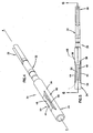
- FIGS. 1-3 illustrate one conventional center conductor 10 that can be used in a switching assembly of a coax jack module.
- a jack plug 12 (partially shown in FIG. 3 ) is inserted into a jack port of the coax jack module such that a pin element 14 of the jack plug 12 is received within an end 16 of the center conductor 10.
- the end 16 of the center conductor 10 has a generally tubular construction 18 that receives the pin element 14 of the jack plug 12.
- the tubular construction 18 includes a crimped contact portion 20 ( FIG. 3 ) that ensures proper contact between the center conductor 10 and the pin element 14 of the jack plug 12.
- FIGS. 1 and 2 illustrate the center conductor 10 prior to formation of the crimped contact portion 20.
- the crimped contact portion 20 is located in a region 22 at which two opposing slots 24, 26 are located.
- the opposing slots 24, 26 are positioned 180 degrees from one another.
- the slots 24, 26 accommodate crimping of the tubular construction 18 (i.e. the inward displacement of material), and permit the crimped contact portion 20 to expand when a pin element is inserted into the center conductor. That is, the crimped contact portion 20 functions as a spring beam for mechanical connection to the pin element 14 of the jack plug 12.
- the contact portion 20 is crimped about the entire circumference (360 degrees) of the tubular construction 18.
- a center conductor according to the preamble of claim 1 is disclosed in GB993316A .
- One aspect of the present invention is a center conductor according to claim 1.
- Another aspect of the present invention is a method of manufacturing a center conductor according to claim 8.
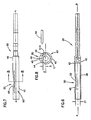
- FIG. 4 illustrates one embodiment of center conductor 30 with a crimped region 50 having features that are examples of how inventive aspects in accordance with the principles of the present disclosure may be practiced. Preferred features are adapted for improving structural reliability and life cycle use of the center conductor, while ensuring proper electrical contact with pin elements of jack plugs.
- the center conductor 30 includes a conductive body 32 having a first end 34 and a second end 36.
- the conductive body 32 includes a tubular structure 38 located at the first end 34.
- the tubular structure 38 defines an inner diameter D1 ( FIG. 6 ) sized for receipt of a pin element (e.g. 14 in FIG. 3 ) of a jack plug.
- the inner diameter D1 of the tubular structure 38 is generally between about 0.762 millimeters (0.030 inches) and 0.864 millimeters (0.034 inches); more preferably about 0.813 millimeters (0.032 inches).
- the conductive body 32 of the center conductor 30 defines a central, longitudinal axis A-A.
- the longitudinal axis A-A is generally concentric with the inner diameter D1 of the tubular structure 38.
- the longitudinal axis A-A defines a plane P that bisects the conductive body 32 to define a first body half 40 and a second body half 42.
- the crimped region 50 of the center conductor 30 is located in only one of the either the first body half 40 or the second body half 42. What is meant by crimped region is the region at which material is radially displaced, generally toward the center or longitudinal axis A-A of the center conductor. In the illustrated embodiment, the crimped region 50 is located only within the first body half 40 of the center conductor 30.
- the crimped region includes first and second elongated slots 44, 46 formed in the tubular structure 38 of the center conductor 30.
- Other numbers of slots 44, 46 can be provided in accordance with the principle disclosed.
- the elongated slots 44, 46 extend parallel with the longitudinal axis A-A of the center conductor 30.
- the elongated slots 44, 46 are provided only in the first half 40 of the center conductor 30.
- the elongated slots 44, 46 are located a distance S ( FIG. 8 ) from the plane P that bisects the center conductor 30.
- the slots 44, 46 are located to provide an uninterrupted tubular region 90 of approximately 270 degrees (a region equal to approximately 75% of the diameter of the tubular structure 38).
- the uninterrupted tubular region 90 increases the structural stability and strength of the tubular structure 38 and thereby improves the mechanical reliability of the center conductor 30.
- the first and second elongated slots 44, 46 define a contact member or contact portion 48.
- the contact member 48 is the portion of the conductive body 38 that lies between the first and second slots 44, 46 formed in the first half 40 of the conductive body 38.
- the contact member 48 is crimped so that at least a central portion 52 of the contact member 48 radially projects into the inner diameter D1 of the tubular structure 38 of the center conductor 30.
- the crimped contact member 48 functions as a spring member that ensures proper electrical connection between a pin element of a jack plug and the center conductor.
- the contact member 48 at the crimped region 50 of the center conductor includes first and second ends 54, 56 integrally connected to the conductive body 32 of the center conductor 30.
- the first and second ends 54, 56 are wider than the central portion 52 of the contact member 48.
- the first and second ends narrow or taper toward the center portion 52 of the contact member 48.
- the wider first and second ends 54, 56 increase the structural strength of the contact member 48 at the ends 54, 56 to prevent the contact member 48 from crushing or tearing during insertion of a pin element.
- the hourglass shape or tapered configuration of the contact member 48 is provided via the manufacturing of the first and second elongated slots 44, 46.
- the first and second elongated slots 44, 46 are formes by saw cuts.
- the saw cuts are provided by a saw blade 58 oriented at an angle parallel to the plane P that bisects the conductive body 32.
- the saw cuts or slots 44, 46 are formed at an angle parallel to the plane P, as opposed to being radially formed or formed perpendicular to the longitudinal axis A-A of the center conductor.
- orienting the saw blade 58 parallel to the plane P provides the tapered or narrowing configuration of the contact member 48.
- the contact member 48 is crimped such that the central portion 52 projects into the inner diameter D1 of the center conductor, as previously described. In the illustrated embodiment, only the contact member 48 is crimped. Crimping only the contact member 48 contributes to the un-interruption of the tubular region 90.
- the tubular region 90 and the crimped region 50 of the center conductor 30 define a circumference C of the conductive body 32.
- the crimped region 50 is located about a portion of the circumference C of the conducive body 32; a remaining portion (i.e. 90) of the circumference C is the uninterrupted portion.
- the uninterrupted region 90 is non-slotted and un-crimped.
- the center conductor 130 includes a crimped region 150 located at the first end 134.
- the crimped region 150 includes first and second elongated slots 144, 146 formed only in a first body half 140 of a conductive body 132.
- the second end 136 of the illustrated center conductor 130 is configured to use in a different module application than that of the first embodiment, as will be described in greater detail hereinafter.
- the center conductor 230 includes a crimped region 250 located at the first end 234.
- the crimped region 250 includes first and second elongated slots 244, 246 formed only in a first body half 240 ( FIG. 11 ) of a conductive body 232.
- the second end 236 of the illustrated center conductor 230 is configured to use in a different module application than that of the previous embodiments, as will be described in greater detail hereinafter.
- the first end 234 of the center conductor 230 is a flared end 235.
- the flared end 235 aids a user in guiding a pin element of a jack plug into the inner diameter (e.g., D1 in FIG. 6 ) of the center conductor 230.
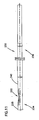
- the center conductor 330 includes a crimped region 350 located at the first end 334 of the center conductor 330.
- the crimped region 350 does not include elongated slots formed in a conductive body 332. Rather, the crimped region 350 is formed by a lancing or punching operation that essentially displaces an amount of material of the conductive body 332 toward the longitudinal axis of the center conductor 330.
- the crimped region 350 defines a contact member 348 formed by the lancing operation. Similar to the previous embodiment, the contact member 348 is formed only in a first body half 340 ( FIG. 18 ) of a conductive body 332.
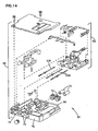
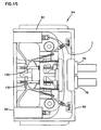
- the center conductors of the present disclosure can be used in a variety of applications, including a coax jack module assembly 60.
- the illustrated coax jack module assembly 60 includes at least one front module component 62 (two are shown) and a rear module component 64.
- the front and rear module components 62, 64 are interconnect to one another by an intermediate connection module 66 having intermediate coaxial cables 76 (shown in part adjacent to each of the front and rear module components 62, 64).
- the front and rear module components 62, 64 and the intermediate connection module 66 can be configured such that the coax jack module assembly 60 provides cross-connect functions, line monitoring, and line access of high speed signals, as desired.
- the front module component 62 of the coax jack module assembly 60 includes a housing 68 that carries a number of switching assemblies 92 ( FIG. 14 ).
- the housing 68 has a front 70 and a rear 80.
- the front 70 of the housing defines ports 72.
- Jack plugs are inserted within the ports 72 such that the pin elements (e.g. 14 in FIG. 3 ) of the jack plugs 12 are received within the center conductors 230 ( FIG. 13 ) of the front module component 62.
- the front module component 62 includes three center conductors 230, each associated with a switching assembly and each located within a port 72 of the housing 68.
- the center conductors 230 used in the illustrated front module component 62 are similar to those shown in FIGS. 10 and 11 .
- the center conductors 230 interconnect to coaxial connectors 74 located at the rear 80 of the housing 68.
- the coaxial connectors 74 are in turn are coupled to the intermediate coaxial cables 76 of the intermediate connection module 66 ( FIG. 12 ).
- the intermediate coaxial cables 76 of the intermediate connection module 66 at least partially interconnect the front module component 62 and the rear module component 64.
- the intermediate coaxial cables 76 of the intermediate connection module 66 provide an interconnection between the coaxial connectors 76 of the front module component 62 and coaxial connectors 78 of the rear module component 64.
- the intermediate connection module 66 also includes coaxial connectors 96 that interconnect to the pieces of equipment.
- the coaxial connectors 96 also preferably include center conductors in accordance with the principles disclosed.
- the rear module component 64 also includes a housing 82 that carries a number of switching assemblies 94 ( FIG. 16 ).
- the housing has a front 84 and a rear 86.
- the coaxial connectors 78 are located at the front 84 of the housing 82 of the rear module component 64.
- the rear 86 of the housing 82 defines ports 88 ( FIG. 16 ).
- Jack plugs are inserted within the ports 88 such that the pin elements (e.g. 14 in FIG. 3 ) of the jack plugs 12 are received within center conductors 130 of the rear module component 64. As shown in FIG.
- the rear module component 64 includes two center conductors 130, each associated with a switching assembly and each located within a port 88 of the housing 82.
- the center conductors 130 used in the illustrated rear module component 64 are similar to those shown in FIG. 9 .
- the center conductors 230 interconnect to coaxial connectors 78 located at the front 84 of the housing 82.
- the front and rear module components 62, 64 can be used in a number of a coax jack module assembly configurations.
- the coax jack module assembly 60 of FIG. 12 is configured to function as a 4-port module assembly.
- a 4-port module assembly provides direct monitoring access to incoming and outgoing signals.
- the front and rear module components 62, 64 can be used in other types or differently configured coax jack modules assemblies, such as a 6-port module assembly, or an interconnect module assembly, and further, a looping module assembly, a non-looping module assembly, or a 75-ohm auto-termination module assembly, for example.
- a 6-port module assembly provides the direct monitoring of signals as provided in the 4-port module, and also provides monitoring of auxiliary incoming cross-connect signals and auxiliary outgoing cross-connect signals.
- An interconnect module assembly is used to directly interconnect two pieces of equipment, as opposed to using more than one module component for cross-connection between the two pieces of equipment.
- the various looping, non-looping and termination configurations relate to options concerning the disposition of alarm signals generated by, and associated feedback to, the pieces of equipment.
- each of the front and rear modules (e.g., 62, 64) of the coax jack module assembly 60 includes a center conductor having a crimped region, as described herein.
- the disclosed crimped region of the center conductor embodiments improve the structural reliability and life cycle of the center conductor, as compared to conventional center conductor arrangements that experienced problematic mechanical failure and premature fatigue.
Landscapes
- Engineering & Computer Science (AREA)
- Computer Networks & Wireless Communication (AREA)
- Coupling Device And Connection With Printed Circuit (AREA)
- Manufacturing Of Electrical Connectors (AREA)
- Insulated Conductors (AREA)
- Superconductors And Manufacturing Methods Therefor (AREA)
- Ropes Or Cables (AREA)
- Burglar Alarm Systems (AREA)
- Slot Machines And Peripheral Devices (AREA)
- Glass Compositions (AREA)
Priority Applications (1)
| Application Number | Priority Date | Filing Date | Title |
|---|---|---|---|
| PL06816358T PL1949708T3 (pl) | 2005-10-27 | 2006-10-11 | Obciskany przewód centralny |
Applications Claiming Priority (2)
| Application Number | Priority Date | Filing Date | Title |
|---|---|---|---|
| US11/260,502 US7252560B2 (en) | 2005-10-27 | 2005-10-27 | Crimped center conductor |
| PCT/US2006/039042 WO2007050260A1 (en) | 2005-10-27 | 2006-10-11 | Crimped center conductor |
Publications (3)
| Publication Number | Publication Date |
|---|---|
| EP1949708A1 EP1949708A1 (en) | 2008-07-30 |
| EP1949708B1 EP1949708B1 (en) | 2010-06-02 |
| EP1949708B9 true EP1949708B9 (en) | 2010-10-06 |
Family
ID=37670880
Family Applications (1)
| Application Number | Title | Priority Date | Filing Date |
|---|---|---|---|
| EP06816358A Not-in-force EP1949708B9 (en) | 2005-10-27 | 2006-10-11 | Crimped center conductor |
Country Status (10)
| Country | Link |
|---|---|
| US (1) | US7252560B2 (ja) |
| EP (1) | EP1949708B9 (ja) |
| JP (1) | JP5044729B2 (ja) |
| KR (1) | KR20080067684A (ja) |
| CN (1) | CN101347004B (ja) |
| AT (1) | ATE470314T1 (ja) |
| BR (1) | BRPI0617958A2 (ja) |
| DE (1) | DE602006014719D1 (ja) |
| PL (1) | PL1949708T3 (ja) |
| WO (1) | WO2007050260A1 (ja) |
Families Citing this family (5)
| Publication number | Priority date | Publication date | Assignee | Title |
|---|---|---|---|---|
| US7377809B2 (en) * | 2006-04-14 | 2008-05-27 | Extreme Broadband Engineering, Llc | Coaxial connector with maximized surface contact and method |
| GB0913863D0 (en) * | 2009-08-08 | 2009-09-16 | Jones David J | Animal collar-guard |
| US7931509B2 (en) * | 2009-09-25 | 2011-04-26 | Glen David Shaw | Coaxial fitting contact tube construction |
| US8888527B2 (en) | 2011-10-25 | 2014-11-18 | Perfectvision Manufacturing, Inc. | Coaxial barrel fittings and couplings with ground establishing traveling sleeves |
| JP5897625B2 (ja) | 2014-03-14 | 2016-03-30 | 大同メタル工業株式会社 | すべり軸受 |
Family Cites Families (17)
| Publication number | Priority date | Publication date | Assignee | Title |
|---|---|---|---|---|
| US3040288A (en) | 1958-02-27 | 1962-06-19 | Phelps Dodge Copper Prod | Means for connecting metal jacketed coaxial cable |
| US3099510A (en) * | 1960-04-25 | 1963-07-30 | Gorn Electric Company Inc | Connector |
| FR1274578A (fr) | 1960-09-12 | 1961-10-27 | Perfectionnements apportés aux systèmes connecteurs du type broche et douille | |
| GB1113923A (en) * | 1964-09-03 | 1968-05-15 | Sealectro Corp | Improvements in or relating to electrical socket contacts |
| US3786558A (en) * | 1971-11-16 | 1974-01-22 | L Mccarthy | Method of making a hollow electrical contact |
| US4304457A (en) * | 1977-12-27 | 1981-12-08 | Sloan Valve Company | Electrical connector |
| GB2054281B (en) | 1979-07-23 | 1983-03-02 | Smiths Industries Ltd | Resilient sockets |
| EP0061587B1 (en) * | 1981-03-16 | 1985-10-30 | CONNEI S.p.A. | A socket member for an electrical connector and a method for making same |
| US4550972A (en) * | 1984-04-09 | 1985-11-05 | Amp Incorporated | Cylindrical socket contact |
| US5116266A (en) * | 1987-10-19 | 1992-05-26 | Gte Products Corporation | Electrical connector |
| US5254022A (en) * | 1989-07-28 | 1993-10-19 | Edward W. Burger | Electrical connector device and method of manufacturer thereof |
| SK283352B6 (sk) | 1992-04-02 | 2003-06-03 | Adc Telecommunications, Inc. | Spojovací modul koaxiálnych káblov |
| WO1994008429A1 (en) * | 1992-10-05 | 1994-04-14 | Adc Telecommunications, Inc. | Jack module assembly |
| US5417588A (en) | 1993-11-15 | 1995-05-23 | Adc Telecommunications, Inc. | Coax connector with center pin locking |
| DE19734524C2 (de) | 1997-08-08 | 1999-07-29 | Framatome Connectors Int | Zylinderförmiger Buchsenkontakt |
| CN1141761C (zh) * | 2001-03-30 | 2004-03-10 | 翁胜嘉 | 同轴微电缆的免焊接连接器 |
| US6551136B2 (en) | 2001-09-20 | 2003-04-22 | Adc Telecommunications, Inc. | Closed end coaxial connector |
-
2005
- 2005-10-27 US US11/260,502 patent/US7252560B2/en not_active Expired - Lifetime
-
2006
- 2006-10-11 JP JP2008537729A patent/JP5044729B2/ja not_active Expired - Fee Related
- 2006-10-11 BR BRPI0617958-4A patent/BRPI0617958A2/pt not_active IP Right Cessation
- 2006-10-11 DE DE602006014719T patent/DE602006014719D1/de active Active
- 2006-10-11 EP EP06816358A patent/EP1949708B9/en not_active Not-in-force
- 2006-10-11 KR KR1020087012593A patent/KR20080067684A/ko not_active Ceased
- 2006-10-11 AT AT06816358T patent/ATE470314T1/de not_active IP Right Cessation
- 2006-10-11 PL PL06816358T patent/PL1949708T3/pl unknown
- 2006-10-11 WO PCT/US2006/039042 patent/WO2007050260A1/en not_active Ceased
- 2006-10-11 CN CN2006800493286A patent/CN101347004B/zh not_active Expired - Fee Related
Also Published As
| Publication number | Publication date |
|---|---|
| JP5044729B2 (ja) | 2012-10-10 |
| JP2009514168A (ja) | 2009-04-02 |
| US20070099521A1 (en) | 2007-05-03 |
| CN101347004B (zh) | 2012-02-29 |
| BRPI0617958A2 (pt) | 2011-08-09 |
| PL1949708T3 (pl) | 2010-10-29 |
| ATE470314T1 (de) | 2010-06-15 |
| WO2007050260A1 (en) | 2007-05-03 |
| KR20080067684A (ko) | 2008-07-21 |
| DE602006014719D1 (de) | 2010-07-15 |
| EP1949708B1 (en) | 2010-06-02 |
| EP1949708A1 (en) | 2008-07-30 |
| CN101347004A (zh) | 2009-01-14 |
| US7252560B2 (en) | 2007-08-07 |
Similar Documents
| Publication | Publication Date | Title |
|---|---|---|
| CN105723571B (zh) | 减少对的以太网接插线以及连接器化线缆的方法 | |
| EP2417673B1 (de) | Elektrischer steckverbinder | |
| US6050842A (en) | Electrical connector with paired terminals | |
| US7871285B1 (en) | Methods and apparatus for terminating electrical connectors to cables | |
| US4054350A (en) | Modular plug for terminating cord having non-planar array of conductors | |
| US8460024B2 (en) | Contact assembly for electrical connector | |
| US9583885B2 (en) | Connector assembly with grounding spring | |
| US6238246B1 (en) | Grounding bracket for a shielded cable connector | |
| JP2006513543A (ja) | ケーブル差込み接続器 | |
| US6080018A (en) | Grounding arrangement for a shielded cable connector | |
| US7568937B2 (en) | Devices for connecting conductors of twisted pair cable to insulation displacement contacts | |
| US4795356A (en) | Electrical tap connector assembly | |
| EP1949708B1 (en) | Crimped center conductor | |
| US4744774A (en) | Electrical connector having conductive sheath-clamping means | |
| US6821142B1 (en) | Electrical connector with crosstalk reduction and control | |
| WO2006036961A1 (en) | High density mount for a co-axial connector | |
| EP2135463A1 (en) | Dsx module with board mounted baluns | |
| US6704992B2 (en) | Cable punch assembly | |
| JPS61224278A (ja) | 電気接続器及び接続方法 | |
| WO2008070558A2 (en) | Multi-position coaxial connector system | |
| US20100330836A1 (en) | Devices for Connecting Conductors of Twisted Pair Cable to Insulation Displacement Contacts | |
| US12470008B2 (en) | Structure of communication connector with cushion | |
| CN219874151U (zh) | 具有靠垫的通讯接头改良结构 | |
| EP1414272B1 (de) | Hörgerät mit einer externen Elektronikkomponente | |
| US20030017751A1 (en) | Quick connect/disconnect terminal block |
Legal Events
| Date | Code | Title | Description |
|---|---|---|---|
| PUAI | Public reference made under article 153(3) epc to a published international application that has entered the european phase |
Free format text: ORIGINAL CODE: 0009012 |
|
| 17P | Request for examination filed |
Effective date: 20080527 |
|
| AK | Designated contracting states |
Kind code of ref document: A1 Designated state(s): AT BE BG CH CY CZ DE DK EE ES FI FR GB GR HU IE IS IT LI LT LU LV MC NL PL PT RO SE SI SK TR |
|
| GRAP | Despatch of communication of intention to grant a patent |
Free format text: ORIGINAL CODE: EPIDOSNIGR1 |
|
| DAX | Request for extension of the european patent (deleted) | ||
| GRAS | Grant fee paid |
Free format text: ORIGINAL CODE: EPIDOSNIGR3 |
|
| GRAA | (expected) grant |
Free format text: ORIGINAL CODE: 0009210 |
|
| RIN1 | Information on inventor provided before grant (corrected) |
Inventor name: KES, JEFFREY Inventor name: WENDLAND, RANDALL |
|
| AK | Designated contracting states |
Kind code of ref document: B1 Designated state(s): AT BE BG CH CY CZ DE DK EE ES FI FR GB GR HU IE IS IT LI LT LU LV MC NL PL PT RO SE SI SK TR |
|
| REG | Reference to a national code |
Ref country code: GB Ref legal event code: FG4D |
|
| REG | Reference to a national code |
Ref country code: CH Ref legal event code: EP Ref country code: CH Ref legal event code: NV Representative=s name: MICHELI & CIE SA |
|
| REG | Reference to a national code |
Ref country code: IE Ref legal event code: FG4D |
|
| REF | Corresponds to: |
Ref document number: 602006014719 Country of ref document: DE Date of ref document: 20100715 Kind code of ref document: P |
|
| REG | Reference to a national code |
Ref country code: NL Ref legal event code: VDEP Effective date: 20100602 |
|
| PG25 | Lapsed in a contracting state [announced via postgrant information from national office to epo] |
Ref country code: LT Free format text: LAPSE BECAUSE OF FAILURE TO SUBMIT A TRANSLATION OF THE DESCRIPTION OR TO PAY THE FEE WITHIN THE PRESCRIBED TIME-LIMIT Effective date: 20100602 Ref country code: SE Free format text: LAPSE BECAUSE OF FAILURE TO SUBMIT A TRANSLATION OF THE DESCRIPTION OR TO PAY THE FEE WITHIN THE PRESCRIBED TIME-LIMIT Effective date: 20100602 |
|
| REG | Reference to a national code |
Ref country code: PL Ref legal event code: T3 |
|
| LTIE | Lt: invalidation of european patent or patent extension |
Effective date: 20100602 |
|
| PG25 | Lapsed in a contracting state [announced via postgrant information from national office to epo] |
Ref country code: AT Free format text: LAPSE BECAUSE OF FAILURE TO SUBMIT A TRANSLATION OF THE DESCRIPTION OR TO PAY THE FEE WITHIN THE PRESCRIBED TIME-LIMIT Effective date: 20100602 Ref country code: FI Free format text: LAPSE BECAUSE OF FAILURE TO SUBMIT A TRANSLATION OF THE DESCRIPTION OR TO PAY THE FEE WITHIN THE PRESCRIBED TIME-LIMIT Effective date: 20100602 Ref country code: LV Free format text: LAPSE BECAUSE OF FAILURE TO SUBMIT A TRANSLATION OF THE DESCRIPTION OR TO PAY THE FEE WITHIN THE PRESCRIBED TIME-LIMIT Effective date: 20100602 Ref country code: SI Free format text: LAPSE BECAUSE OF FAILURE TO SUBMIT A TRANSLATION OF THE DESCRIPTION OR TO PAY THE FEE WITHIN THE PRESCRIBED TIME-LIMIT Effective date: 20100602 |
|
| PG25 | Lapsed in a contracting state [announced via postgrant information from national office to epo] |
Ref country code: CY Free format text: LAPSE BECAUSE OF FAILURE TO SUBMIT A TRANSLATION OF THE DESCRIPTION OR TO PAY THE FEE WITHIN THE PRESCRIBED TIME-LIMIT Effective date: 20100602 Ref country code: GR Free format text: LAPSE BECAUSE OF FAILURE TO SUBMIT A TRANSLATION OF THE DESCRIPTION OR TO PAY THE FEE WITHIN THE PRESCRIBED TIME-LIMIT Effective date: 20100903 |
|
| PG25 | Lapsed in a contracting state [announced via postgrant information from national office to epo] |
Ref country code: EE Free format text: LAPSE BECAUSE OF FAILURE TO SUBMIT A TRANSLATION OF THE DESCRIPTION OR TO PAY THE FEE WITHIN THE PRESCRIBED TIME-LIMIT Effective date: 20100602 Ref country code: NL Free format text: LAPSE BECAUSE OF FAILURE TO SUBMIT A TRANSLATION OF THE DESCRIPTION OR TO PAY THE FEE WITHIN THE PRESCRIBED TIME-LIMIT Effective date: 20100602 |
|
| PG25 | Lapsed in a contracting state [announced via postgrant information from national office to epo] |
Ref country code: IS Free format text: LAPSE BECAUSE OF FAILURE TO SUBMIT A TRANSLATION OF THE DESCRIPTION OR TO PAY THE FEE WITHIN THE PRESCRIBED TIME-LIMIT Effective date: 20101002 Ref country code: BE Free format text: LAPSE BECAUSE OF FAILURE TO SUBMIT A TRANSLATION OF THE DESCRIPTION OR TO PAY THE FEE WITHIN THE PRESCRIBED TIME-LIMIT Effective date: 20100602 Ref country code: SK Free format text: LAPSE BECAUSE OF FAILURE TO SUBMIT A TRANSLATION OF THE DESCRIPTION OR TO PAY THE FEE WITHIN THE PRESCRIBED TIME-LIMIT Effective date: 20100602 Ref country code: PT Free format text: LAPSE BECAUSE OF FAILURE TO SUBMIT A TRANSLATION OF THE DESCRIPTION OR TO PAY THE FEE WITHIN THE PRESCRIBED TIME-LIMIT Effective date: 20101004 Ref country code: RO Free format text: LAPSE BECAUSE OF FAILURE TO SUBMIT A TRANSLATION OF THE DESCRIPTION OR TO PAY THE FEE WITHIN THE PRESCRIBED TIME-LIMIT Effective date: 20100602 |
|
| PGFP | Annual fee paid to national office [announced via postgrant information from national office to epo] |
Ref country code: DE Payment date: 20101027 Year of fee payment: 5 |
|
| PG25 | Lapsed in a contracting state [announced via postgrant information from national office to epo] |
Ref country code: IT Free format text: LAPSE BECAUSE OF FAILURE TO SUBMIT A TRANSLATION OF THE DESCRIPTION OR TO PAY THE FEE WITHIN THE PRESCRIBED TIME-LIMIT Effective date: 20100602 |
|
| PGFP | Annual fee paid to national office [announced via postgrant information from national office to epo] |
Ref country code: GB Payment date: 20101025 Year of fee payment: 5 |
|
| PLBE | No opposition filed within time limit |
Free format text: ORIGINAL CODE: 0009261 |
|
| STAA | Information on the status of an ep patent application or granted ep patent |
Free format text: STATUS: NO OPPOSITION FILED WITHIN TIME LIMIT |
|
| PG25 | Lapsed in a contracting state [announced via postgrant information from national office to epo] |
Ref country code: DK Free format text: LAPSE BECAUSE OF FAILURE TO SUBMIT A TRANSLATION OF THE DESCRIPTION OR TO PAY THE FEE WITHIN THE PRESCRIBED TIME-LIMIT Effective date: 20100602 |
|
| 26N | No opposition filed |
Effective date: 20110303 |
|
| PG25 | Lapsed in a contracting state [announced via postgrant information from national office to epo] |
Ref country code: MC Free format text: LAPSE BECAUSE OF NON-PAYMENT OF DUE FEES Effective date: 20101031 |
|
| REG | Reference to a national code |
Ref country code: DE Ref legal event code: R097 Ref document number: 602006014719 Country of ref document: DE Effective date: 20110302 |
|
| PG25 | Lapsed in a contracting state [announced via postgrant information from national office to epo] |
Ref country code: FR Free format text: LAPSE BECAUSE OF NON-PAYMENT OF DUE FEES Effective date: 20101102 |
|
| REG | Reference to a national code |
Ref country code: FR Ref legal event code: ST Effective date: 20110630 |
|
| PG25 | Lapsed in a contracting state [announced via postgrant information from national office to epo] |
Ref country code: IE Free format text: LAPSE BECAUSE OF NON-PAYMENT OF DUE FEES Effective date: 20101011 |
|
| PGFP | Annual fee paid to national office [announced via postgrant information from national office to epo] |
Ref country code: PL Payment date: 20110922 Year of fee payment: 6 |
|
| PGFP | Annual fee paid to national office [announced via postgrant information from national office to epo] |
Ref country code: CZ Payment date: 20111004 Year of fee payment: 6 Ref country code: CH Payment date: 20111025 Year of fee payment: 6 |
|
| PG25 | Lapsed in a contracting state [announced via postgrant information from national office to epo] |
Ref country code: BG Free format text: LAPSE BECAUSE OF FAILURE TO SUBMIT A TRANSLATION OF THE DESCRIPTION OR TO PAY THE FEE WITHIN THE PRESCRIBED TIME-LIMIT Effective date: 20100602 Ref country code: HU Free format text: LAPSE BECAUSE OF FAILURE TO SUBMIT A TRANSLATION OF THE DESCRIPTION OR TO PAY THE FEE WITHIN THE PRESCRIBED TIME-LIMIT Effective date: 20101203 Ref country code: LU Free format text: LAPSE BECAUSE OF NON-PAYMENT OF DUE FEES Effective date: 20101011 |
|
| PG25 | Lapsed in a contracting state [announced via postgrant information from national office to epo] |
Ref country code: TR Free format text: LAPSE BECAUSE OF FAILURE TO SUBMIT A TRANSLATION OF THE DESCRIPTION OR TO PAY THE FEE WITHIN THE PRESCRIBED TIME-LIMIT Effective date: 20100602 |
|
| REG | Reference to a national code |
Ref country code: CH Ref legal event code: PL |
|
| GBPC | Gb: european patent ceased through non-payment of renewal fee |
Effective date: 20121011 |
|
| PG25 | Lapsed in a contracting state [announced via postgrant information from national office to epo] |
Ref country code: GB Free format text: LAPSE BECAUSE OF NON-PAYMENT OF DUE FEES Effective date: 20121011 Ref country code: CZ Free format text: LAPSE BECAUSE OF NON-PAYMENT OF DUE FEES Effective date: 20121011 Ref country code: DE Free format text: LAPSE BECAUSE OF NON-PAYMENT OF DUE FEES Effective date: 20130501 Ref country code: LI Free format text: LAPSE BECAUSE OF NON-PAYMENT OF DUE FEES Effective date: 20121031 Ref country code: CH Free format text: LAPSE BECAUSE OF NON-PAYMENT OF DUE FEES Effective date: 20121031 |
|
| REG | Reference to a national code |
Ref country code: DE Ref legal event code: R119 Ref document number: 602006014719 Country of ref document: DE Effective date: 20130501 |
|
| PG25 | Lapsed in a contracting state [announced via postgrant information from national office to epo] |
Ref country code: BG Free format text: LAPSE BECAUSE OF FAILURE TO SUBMIT A TRANSLATION OF THE DESCRIPTION OR TO PAY THE FEE WITHIN THE PRESCRIBED TIME-LIMIT Effective date: 20100902 |
|
| PG25 | Lapsed in a contracting state [announced via postgrant information from national office to epo] |
Ref country code: ES Free format text: LAPSE BECAUSE OF FAILURE TO SUBMIT A TRANSLATION OF THE DESCRIPTION OR TO PAY THE FEE WITHIN THE PRESCRIBED TIME-LIMIT Effective date: 20100913 |
|
| PG25 | Lapsed in a contracting state [announced via postgrant information from national office to epo] |
Ref country code: PL Free format text: LAPSE BECAUSE OF NON-PAYMENT OF DUE FEES Effective date: 20121011 |