EP1949670B1 - Electronic camera - Google Patents
Electronic camera Download PDFInfo
- Publication number
- EP1949670B1 EP1949670B1 EP06822543A EP06822543A EP1949670B1 EP 1949670 B1 EP1949670 B1 EP 1949670B1 EP 06822543 A EP06822543 A EP 06822543A EP 06822543 A EP06822543 A EP 06822543A EP 1949670 B1 EP1949670 B1 EP 1949670B1
- Authority
- EP
- European Patent Office
- Prior art keywords
- image
- interest
- regions
- display
- face
- Prior art date
- Legal status (The legal status is an assumption and is not a legal conclusion. Google has not performed a legal analysis and makes no representation as to the accuracy of the status listed.)
- Expired - Fee Related
Links
Images


Classifications
-
- H—ELECTRICITY
- H04—ELECTRIC COMMUNICATION TECHNIQUE
- H04N—PICTORIAL COMMUNICATION, e.g. TELEVISION
- H04N23/00—Cameras or camera modules comprising electronic image sensors; Control thereof
- H04N23/60—Control of cameras or camera modules
- H04N23/61—Control of cameras or camera modules based on recognised objects
- H04N23/611—Control of cameras or camera modules based on recognised objects where the recognised objects include parts of the human body
-
- H—ELECTRICITY
- H04—ELECTRIC COMMUNICATION TECHNIQUE
- H04N—PICTORIAL COMMUNICATION, e.g. TELEVISION
- H04N23/00—Cameras or camera modules comprising electronic image sensors; Control thereof
- H04N23/60—Control of cameras or camera modules
- H04N23/63—Control of cameras or camera modules by using electronic viewfinders
- H04N23/633—Control of cameras or camera modules by using electronic viewfinders for displaying additional information relating to control or operation of the camera
- H04N23/635—Region indicators; Field of view indicators
-
- H—ELECTRICITY
- H04—ELECTRIC COMMUNICATION TECHNIQUE
- H04N—PICTORIAL COMMUNICATION, e.g. TELEVISION
- H04N23/00—Cameras or camera modules comprising electronic image sensors; Control thereof
- H04N23/60—Control of cameras or camera modules
- H04N23/67—Focus control based on electronic image sensor signals
- H04N23/675—Focus control based on electronic image sensor signals comprising setting of focusing regions
Definitions
- the present invention relates to an electronic camera , an image processing apparatus, an image processing method and a computer program product . More specifically, the invention relates to a technique for recognizing a photographed face image of an object.
- photographed images of objects can be checked on screens such as liquid crystal monitors provided on the rear surfaces of the cameras.
- screens such as liquid crystal monitors provided on the rear surfaces of the cameras.
- Jpn. Pat. Appln. KOKAI Publication No. 8-63597 discloses a method of determining a face candidate region corresponding to a shape of a person's face and determining a face region from the feature quantity in the face candidate region so as to extract the person's face from a color original image.
- Jpn. Pat. Appln. KOKAI Publication No. 2004-240829 discloses a technique for detecting an edge from face portrait image data developed in a memory, extracting a pair of edges as candidates of both eyes, narrowing the candidates according to the feature of the person's face, estimating a face region in the facial portrait image data from the narrowed position of both eyes, obtaining a correcting amount from an average value of luminance in the estimated face region, and correcting the facial portrait image data according to the correcting amount so as to adjust brightness of the facial portrait image data.
- Jpn. Pat. Appln. KOKAI Publication No. 6-217187 discloses a technique for adjusting a zoom so that the size of a face portion of an image becomes uniform so as to obtain a stable image even when an object moves.
- Jpn. Pat. Appln. KOKAI Publication No. 2003-323615 discloses a technique for accepting a person's face image as a sample image, detecting a region in the vicinity of the face on the image input using a feature of the input sample image, displaying candidates of the detected region in the vicinity of the face on the image, and inputting a narrowing condition for the displayed candidate of the area in the vicinity of the face as to whether the displayed image is a face image so as to execute a face detecting process.
- Jpn. Pat. Appln. KOKAI Publication Nos. 5-268513 , 9-233384 and 11-84481 disclose techniques for, when a person's face image displayed on a screen is small, enlarging the face image by means of cropping so as to display it on the monitor screen.
- JP 2005-269563 A relates to an image processor and an image reproducing apparatus, wherein the face of a person is detected from a photographed image, and the face of the person is segmented into a predetermined size to create the face thumbnail of a predetermined size. Then, the image data of the face thumbnail is recorded into an image file together with image data of a photographed image (main image).
- WO 2005/006072 A1 refers to an object decision device and an imaging device, wherein face detection is executed only for an image imaged according to predetermined arbitrary focal information.
- face detection a personal face is detected according to a relative value of a statistical amount in a plurality of characteristic regions generated by convexes/concaves and organs of the personal face. Accordingly, even when the face of the image used for face detection is unclear, it is possible to obtain a statistical amount in a certain region and to detect such a face. Consequently, it is possible to rapidly detect a main object as a focusing object without performing focal control in the stage of preliminary imaging in the image device.
- EP 1 589 478 A2 relates to an apparatus for magnifying an image, which is capable of easily displaying a magnified image of a subject intended for by the user.
- An intended subject such as the face of a man is detected from the image displayed on the screen, and in accordance with position and size of the intended subject detected, the display area and the magnification rate for magnified display of the intended subject are determined.
- the magnified display is conducted on the screen.
- the intended subjects are classified into a plurality of masses and the magnified display may be conducted for each mass.
- an electronic camera comprising an image processing section which, when a plurality of people are present in an object image, recognizes face images from the object image; an image operating section which accepts an instruction for sequentially switching the face images to be displayed on a display section; and a control section which controls the face images so that they are enlarged and sequentially switched to be displayed on the display section according to the instruction accepted by the image operating section.
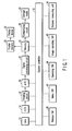
- FIG. 1 is a block diagram illustrating a schematic constitution of an electronic camera according to a first embodiment of the present invention.
- a system controller 10 is control means for controlling a control operation of the entire electronic camera, and is composed of a CPU or the like.
- the system controller 10 is connected to a photographing lens 12 which is built into a lens barrel, not shown, a CCD 14 as an imaging element which images an optical image of an object via the photographing lens 12, an imaging circuit 16 which converts the optical image captured by the CCD 14 into an electrical signal, an analog-to-digital converter 18, a signal processing circuit 20 and a memory 22.
- the system controller 10 is connected to a distance measuring unit 34, a release switch (SW) 38, a menu switch (SW) 40, an image operating switch (SW) 42 and an operating switch (SW) 44.
- the memory 22 is connected to a storage media 30 via a compressing circuit 28 and to a display device 32 via a display memory 26.
- the distance measuring unit 34 is for obtaining a focussing position of an object (not shown) according to automatic measurement of distance.
- the release switch 38 corresponds to a release button 52, mentioned later, for starting a photographing operation, and has a two-tiered constitution including a first release switch and a second release switch.
- the first release switch is in an ON state so that photographing preparing operations such as a photometry process and a distance measuring process are performed.
- the second release switch is turned on, so that an exposing operation is executed.
- the menu switch 40 is for operating various functions of the electronic camera.
- the image operating switch 42 is for switching an image to be displayed on the display device 32.
- the image operating switch 42 is composed of a face image browsing mode switch 58, an image switching button 60, an object switching button 62 and the like, mentioned later. When these buttons are operated, an image to be displayed on the display surface of the display device 32 is switched.
- the operating switch 44 corresponds to an operating button such as a power switch necessary for operating the camera.
- the photographing lens 12, the CCD 14, the imaging circuit 16, the analog-to-digital converter 18, the signal processing circuit 20, the memory 22, the display memory 26, the compressing circuit 28, the storage media 30, the display device 32, the distance measuring unit 34 are well known. For this reason, their details are omitted.
- an optical image of an object which passes through the photographing lens 12 is converted into an electric signal by the CCD 14, and the electric signal is converted into an analog image signal by the imaging circuit 16.
- the analog image signal is converted into a digital image signal (hereinafter, "image information") by the analog-to-digital converter 18, and a process for converting color information of the image information, a pixel count converting process, a process for recognizing a face image and the like are executed in the signal processing circuit 20.
- image information which is subject to various image processes by the signal processing circuit 20 is stored in the nonvolatile memory 22.
- the memory 22 is composed of a high-speed storage unit, for example, SDRAM, and is used also as a work area for an image process, mentioned later.
- the image information which is once stored in the memory 22 is compressed into JPEG format, for example, by the compressing circuit 28, and is stored in the storage media 30 such as smart media (registered trademark).
- the image signal which is subject to the signal process is transferred from the memory 22 to the display memory 26, and is displayed on the display device 32 via a driving circuit, not shown.
- the stored image is decompressed by an expanding circuit, not shown, and after the image is subject to a predetermined image process by the signal processing circuit 20, the image is displayed on the display device 32 similarly to the photographing case.
- FIG. 3 is a rear view viewed from a rear side of the electronic camera illustrating a constitution of the electronic camera according to the first embodiment of the present invention.
- the release button 52 corresponding to the release switch 38, and a photographing mode switch 54 for selecting a photographing mode are provided above a camera main body 50a.
- a liquid crystal display 60 as the display device 32 is provided to an approximately center of a rear side of the camera main body 50a.
- a face image browsing mode switch 62 for operating a face image browsing mode whose details are mentioned later is provided to the left side of the liquid crystal display 60.
- the right side of the liquid crystal display 60 is provided with an image switching button 64 for switching one frame of image currently displayed on the liquid crystal display 60, and an object switching button 66 for switching to select an object displayed on the liquid crystal display 60.
- the image switching button 64 is composed of a switching button 64a for switching an image into an image one frame after the currently displayed image so as to display it, and a switching button 64b for switching an image into an image one frame before the current displayed image so as to display it.
- step S1 When a power switch, not shown, is turned on, an object is photographed in step S1.
- a plurality (in this case, five) of people 70a to 70e are present in an object image obtained by photographing objects.
- the image is transmitted from the CCD 14 via the imaging circuit 16 and the analog-to-digital converter 18 to the signal processing circuit 20 as mentioned above.
- the signal processing circuit 20 then executes a color information converting process, a pixel count changing process, a face image recognizing process and the like in step S2.
- the face image recognizing process is well known, and since its detail is described in, for example, Jpn. Pat. Appln. KOKAI Publication No. 2004-240829 , its explanation is omitted.
- the signal processing circuit 20 determines regions of interest (ROI) as regions according to the face images in step S3.
- an image shown in FIG. 5 is displayed on the liquid crystal display 50.
- the region of interest for the face image includes five regions designated by 72a to 72e correspondingly to people 70a to 70e.
- the sizes of the region of interest, coordinate start positions and the like of these regions are stored in the memory 22.
- image information about results of the color information converting process and the image count converting process are stored in the memory 22.
- the face image browsing mode switch 62 is pressed down in step S4, and the face image browsing mode is executed according to the following steps.
- the face image in the region of interest positioned on the upper left portion of the screen is enlarged to be displayed in the raster order based on the contents in the memory 22 in step S5.
- "1" is set as the face image N.
- the region of interest 72b having the higher order in the raster order, namely, the face image of the person 70b is displayed as an enlarged image 74b on the liquid crystal display 60 as shown in FIG. 6A .
- a position on the screen of FIG. 5 which corresponds to the region of interest 72b to be displayed as the enlarged image 74b, is displayed on the liquid crystal display 60 in a superimposing manner. That is to say, a screen frame 76 displayed in the superimposing manner shows the entire screen of the liquid crystal display 60. A display region 78a in the screen frame 76 corresponds to the region of interest 72b in FIG. 5 . A user, therefore, can check the enlarged image 74b shown in FIG. 6A and simultaneously the position on the screen where the enlarged image 74b is present on the liquid crystal display 60.
- step S6 A state of the object switching button 66 is detected in step S7.
- step S8 When the object switching button 66 is pressed down, the sequence goes to step S8, but when it is not pressed down, the sequence goes to step S6. That is to say, steps S6 and S7 are repeated until the object switching button 66 is pressed down.
- step S7 when the detection is made in step S7 that the object switching button 66 is pressed down, the sequence goes to step S8, so that a determination is made whether the face image N set in step S5 is N1. In this case, since "1" is set as N in step S5 and "5" is set as the number of the object's faces N1 in step S3, the sequence goes to step S9 so that N is incremented.
- the region of interest related to the face image of the N-numbered object is enlarged to be displayed on the liquid crystal display 60 in step S11.
- a display region 78c in the screen frame 76 corresponding to the region of interest 72c in FIG. 5 is displayed on the liquid crystal display 60 in the superimposing manner. Thereafter, the sequence goes to step S6 so that the camera is in the input standby state.
- step S8 N1 is established in step S8. That is to say, in the first embodiment, the enlarged image 74b, the screen frame 76 and the display region 78a (see FIG. 6A ) are displayed on the liquid crystal display 60 firstly. Thereafter, every time when the object switching button 66 is pressed down, the enlarged image 74c, the screen frame 76 and a display region 78c (see FIG. 6B ) are displayed, an enlarged image 74a, the screen frame 76 and a display region 78a (see FIG. 6C ) are displayed, an enlarged image 74e, the screen frame 76 and a display region 78e (see FIG. 6D ) are displayed, and an enlarged image 74d, the screen frame 76 and a display region 78d (see FIG. 6E ) are displayed sequentially on the liquid crystal display 60.
- the enlarged images 74a to 74e are displayed with the approximately same size on the liquid crystal display 60.
- the object switching button 66 is operated, and a plurality of face images are selectively switched so as to be capable of being displayed in the approximately same size. Therefore, the respective faces and a good photographed state are easily checked.
- a position on the photographed image, in which the enlarged image currently displayed on the liquid crystal display 60 is present, can be easily checked by the screen frame 76 and the display regions 78a to 78e to be displayed on the liquid crystal display 60.
- the sizes of the region of interest and the coordinate start positions are stored, but the present invention is not limited to this, and thus the center point of the region of interest may be stored.
- the raster order is different from the display order in FIG. 6 .
- step S2 the processes after step S2 can be executed under the condition that the face image browsing mode is specified by the user.
- a detection when a detection is made that the face image browsing mode switch 62 is operated, a detection may be made that the face image browsing mode is specified by the user.
- Step S4 is omitted.
- an object image can be selected from a plurality of images saved in the storage media 30 at a reproducing mode for user's browsing of a photographed object image. That is to say, the object image is selected by the user at the reproducing mode, and the signal processing circuit 46 executes the processes after step S2 on the object image selected instead of the object image from the analog-to-digital converter 18 under the condition that the face image browsing mode is specified by the user.
- step S4 is omitted, and the user's selection of the object image is accepted by the operation of the image switching button 64, and the specifying of the face image browsing mode can be accepted by the operation of the face image browsing mode switch 62.
- the electronic camera can be constituted like the modified example shown in FIG. 2B .
- the signal processing circuit 20 executes the color information converting process, the pixel count converting process and the like on the image information (object image) from the analog-to-digital converter 18, the image information is stored in the memory 22.
- the image information stored in the memory 22 is transmitted to the compressing circuit 28 so as to be compressed as mentioned above and is transmitted to the signal processing circuit 46 for recognizing the face images.
- the processes after step S2 are executed on the image information. In this case, step S4 is omitted.
- step S6 When the face image browsing mode switch 36 is pressed down in step S6, the photographing mode or the reproducing mode is selected.
- only one object switching button 66 is provided to the camera main body 50a, and every time when the object switching button 66 is pressed down, the enlarged images are switched to be displayed sequentially according to the raster order.
- four object switching buttons are provided, and desired enlarged images can be switched to be displayed according to the user's selection.
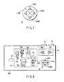
- FIG. 7 is a diagram illustrating a constitutional example of the object switching button according to the first modified example of the first embodiment.
- the object switching button 80 is composed of a switching button (R) 80a for switching an image into an image one frame after so as to display it, a switching button (L) 80b for switching an image into an image one frame before so as to display it, a switching button (U) 80c for enlarging an image, and a switching button (D) 80d for reducing an image.
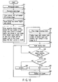
- the camera main body 50b provided with the object switching button 80 is constituted as shown in FIG. 8 .
- the part of the constitution other than the object switching buttons 80 is the same as that in the first embodiment, like members are designated by like reference numerals and the explanation thereof is omitted.
- FIG. 9 is a flowchart explaining the operation for checking a face image in the electronic camera according to the first modified example in the first embodiment.
- the processing operations in steps S21 to S25 are similar to those in the explanation related to steps S1 to S5 in the flowchart of FIG. 4 .
- step S21 When the power switch, not shown,'is turned on, objects are photographed in step S21.
- the well-known face image recognizing process is executed in step S22.
- the regions of interest (ROI) of face images and the number of objects' faces N1 on the screen are stored in the memory 22 in step S23.
- the face image browsing mode switch 36 is pressed down in step S24, so that the face image browsing mode is executed.
- the face image in an upper left part of the screen is enlarged and displayed in the raster order in step S25, so that.the face image N is set to "1".
- the camera is in the input standby state in step S26, and a button of the object switching buttons 80 which is pressed down is detected. That is to say, when the object switching button (L) 80b is pressed down, the sequence goes to step S27, and when the object switching button (R) 80a is pressed down, the sequence goes to step S31.
- the object switching button (U) 80c is pressed down, the sequence goes to step S36, and when the object switching button (D) 80d is pressed down, the sequence goes to step S90.
- step S28 determines whether the face image N set in step S25 is N1.
- N is "1”
- step S28 when N is not "1" in step S28, the sequence goes to step S29, and N is decremented. As mentioned later, this is executed in order to display an face image of the last object in the case where the face images of the second and after objects are displayed by the object switching button (R) 80a. As a result, for example, the enlarged image 74c shown in FIG. 6B is switched into the enlarged image 74b shown in FIG. 6A .
- step S32 determines whether the face image N is equal to the number N1 of the objects' faces on the screen set in step S25.
- N is not equal to N1
- the sequence goes to step S33, so that N is incremented.
- the incremented face image of the N-th object is enlarged to be displayed on the liquid crystal display 60 in step S35.
- step S32 N1 is established in step S32, the sequence goes to step S34, N is again set to "1".
- N N1
- the display reaches the number of the face images of the objects set in steps S23, the display returns to the face image of the first object. Therefore, at next step S35, the face image of the N-th, namely, the first object is enlarged to be displayed on the liquid crystal display 60.
- step S35 After the enlarged display in step S35, the sequence goes to step S26 so that the camera is in the input standby state.
- step S37 so that a current enlargement scale X is compared with a predetermined maximum threshold value of the enlargement scale Thr_1.
- the sequence goes to step S38 so that the current enlargement scale X is set to a predetermined scale A (for example, ⁇ 1.1).
- the sequence then goes to step S44, and the face image displayed in step S25 or S35 is displayed at the enlargement scale X set in step S38 on the liquid crystal display 35.
- step S37 when the enlargement scale X exceeds the predetermined maximum threshold value Thr_1 of the enlargement scale in step S37, the sequence goes to step S39, so that the maximum threshold value of the predetermined enlargement Thr_1 is set as the current enlargement scale X. The sequence then goes to step S44, and the face image displayed in step S25 or S35 is displayed at the enlargement scale X set in step S38 on the liquid crystal display 60.
- step S41 so that the current enlargement scale X is compared with a predetermined minimum threshold value of the enlargement scale Thr_2.
- step S44 the face image displayed in step S25 or S35 is displayed at the enlargement scale X set in step S42 on the liquid crystal display 60.
- step S41 when the enlargement scale X is less than the predetermined minimum threshold value of the enlargement scale Thr_2 in step S41, the sequence goes to step S43, and the predetermined minimum threshold value of the enlargement scale Thr_2 is set as the current enlargement scale X.
- step S44 the face image to be displayed in step S25 or S35 is displayed at the enlargement scale X set in step S43 on the liquid crystal display 60.
- step S44 After the enlarged display in step S44, the sequence goes to step S26, and the camera is in the input standby state.
- the object switching buttons 80a to 80d are operated so that the plural face images can be selectively switched so as to be displayed with the approximately same size, and the face images can be changed into desired sizes so as to be displayed.
- the screen frames and the display regions can be displayed on the liquid crystal display in the superimposing manner.
- a position on the photographed image where the enlarged image displayed on the liquid crystal display 60 is present can be easily checked by the display regions 78a to 78e.
- the size of the region of interest and the coordinate start position are stored, but the center point of the range of interest, a point on the upper left of the region of interest or the like may be stored as the raster order.
- the raster order is different from the display order shown in FIG. 6 .
- the face images on the left part of the screen are sequentially enlarged to be displayed in the raster order.
- the face images are tried to be displayed precisely according to the raster order, this makes a difference between the raster order and the user's perception of the order from upper left to lower right.
- an image on the monitor screen is divided into a plurality of divided regions, and the images on the regions are displayed according to the divided order.
- step S51 When the power switch, not shown, is turned on, objects are photographed in step S51.
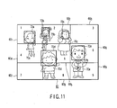
- a plurality of people (in this case, five) 70a to 70e are present as the objects as shown in FIG. 11 .
- the face image recognizing process is executed in step S52.
- the processes after step S52 may be executed after specifying of the face image browsing mode is accepted.
- an image shown in FIG. 11 is displayed on the liquid crystal display 60.
- the five regions of interest for the face images are designated by 72a to 72e for respective people 70a to 70e. Information about them are stored.
- the object image is divided into divided regions with indexes in step S54. In this case, the object image is divided into nine divided regions (1) 60 1 to (9) 60 9 as shown in FIG. 11 .
- the divided regions (1) to (9) indicate the numbers 1 to 9 given to the respective regions in FIG. 11 .
- the indexes of the divided regions and the indexes of the face images are stored in step S55.
- one divided region includes two or more face images
- a face image where the start position of the region of interest is smaller has small index.
- the center points of the regions of interest are expressed by the raster order
- the face images of two people 70b and 70c are present in the divided region (2) 60 2 .
- the region of interest 72b whose start position is smaller has an index smaller than that of the region of interest 72c.
- step S56 The face image browsing mode switch 62 is pressed down in step S56, so that the face image browsing mode is executed.
- step S57 an image, where the index number of its divided region and the index number of its face image are the smallest, is enlarged to be displayed, and the face image N is set to "1".
- step S58 the sequence goes to step S58, and the camera is in the input standby state. Since the respective processing operations in steps S58 to S63 are similar to steps S6 to S11 in the flowchart of FIG. 4 , corresponding step numbers are referred to and the explanation thereof is omitted.
- the enlarged images in the regions of interest 72a, 72b, 72c, 72d and 72e are displayed sequentially in this order.
- a difference between the order of actually displaying the enlarged images and the user's perception can be prevented.
- the screen frame and the display region can be displayed on the liquid crystal display in the superimposing manner.
- the center point of the region of interest is used, but an upper left point of the region of interest or the like may be used.
- the object switching button 66 is operated to switch the image of the object's face to another, as explained above.
- four object switching buttons 80a to 80d may of course be used to switch the image, as in the fist modified example described above.
- the enlarged images are displayed in the raster order, but in the second embodiment, evaluated values of recognition of the objects' face images are calculated, so that the display of the enlarged images is switched according to the order of the evaluated values.
- step S71 When the power switch, not shown, is turned on, the objects are photographed in step S71, and face images are recognized in step S72.
- the evaluated values of the face image recognition are calculated in step S73.
- the processes after step S72 may be executed after the specifying of the face image browsing mode is accepted.
- the evaluated values are determined by the degree of similarity which is also called a matching degree with respect to templates having predetermined facial shape in the recognizing method for recognizing a person's face from an image.
- the face image recognizing method utilizing the matching degree, plural types of face-shaped templates are prepared, the matching degree between the templates and an image is calculated according to normalization intercorrelation, and a template having the highest matching degree is selected.
- a region in the selected template is determined as a face candidate region.
- an eye region may be extracted so that a face region is recognized in the face candidate region, or a mouth, hair, a neck and the like are extracted from eye position information so that a face region may be recognized.
- the regions of interest for the face image include the five regions of interest 72a to 72e for respective people 70a to 70e.
- the face image browsing mode switch 62 is pressed down, the face image browsing mode is executed in step S75.
- the face image with the highest evaluated value of the face image recognition calculated in step S73 is enlarged to be displayed in step S76, and the face image N is set to 1.
- the face images N having the higher evaluated values calculated in step S73 are set to "1", "2", ... in this order.
- step S77 Thereafter, the camera is in the input standby state in step S77.
- the state of the object switching button 66 is detected in step S78.
- steps S77 and S78 are repeated until the object switching button 66 is pressed down.
- the sequence goes to step S79 so that a determination is made whether the set face image N set in step S76 is N1.
- step S80 The sequence goes to step S80 and the N is incremented until face image N is equal to N1.
- the region of interest relating to the object's face image with N-th evaluated value is enlarged to be displayed on the liquid crystal display 60 in step S82.
- step S81 the sequence goes to step S81, and the face image N is set to "1" so that the first face image is displayed.
- the camera is again in the input standby state in step S77.
- the high-precision face image can be checked for the faces and a good photographed state.
- the screen frame and the display region can be displayed on the liquid crystal display in the superimposing manner.
- the face images are displayed on the liquid crystal display sequentially in decreasing order of the evaluated values of the face image recognition, but the present invention is not limited to this, and thus they may be displayed in increasing order of the evaluated values.
- the face images are switched by the object switching button 66, but the present invention is not limited to this, and thus the four object switching buttons 80a to 80d may be used like the first modified example of the first embodiment.
- the evaluated value of the face image recognition for example, an attention is paid to eye portions of objects, and eye shutting states are evaluated by the method disclosed in Jpn. Pat. Appln. KOKAI Publication No. 2003-287784 so that the images may be displayed in decreasing order or increasing order of the evaluated values.
- the enlarged face images are displayed in such a manner that focus estimated positions are switched in order of being closer to the camera in cooperation with focus detection.
- step S91 When the power switch, not shown, is turned on, the well-known face image recognizing process is executed in step S91.
- the regions of interest and the number of regions of interest N1 on the face images are stored in step S92.
- the distance measuring unit 34 executes a focus detecting process according to a well-known contrast method in step S93.
- the contrast method is disclosed in, for example, Japanese Patent Publication No. 2507144 .
- An estimated lens position (step number) of the photographing lens 12 where the focus is the best, namely, the evaluated value is the largest in the regions of interest on the images is stored in the memory 22 in step S94.
- the focus position is controlled as the lens position to be the best focus in step S95, and photographing is carried out in step S96.
- step S97 After photographing, when the face image browsing mode switch 62 is pressed down in step S97, the face image browsing mode is executed.
- the region of interest on the object's face image whose focus estimated position obtained in step S94 is the closest to the camera is enlarged to be displayed in step S98, and the face image N is set to "1". In this case, as the distance from the camera is greater, the face images N are "1", "2", ... according to the focus detecting process in step S93.
- step S99 The state of the object switching button 38 is detected in step S100.
- steps S99 and S100 are repeated until the object switching button 38 is pressed down.
- step S101 the sequence goes to step S101, and a determination is made whether the face image N sent in step S98 is N1.
- step S102 The sequence goes to step S102 and N is incremented until the face image N is equal to N1.
- the face image of the object which is the N-th closest to the camera is enlarged to be displayed on the liquid crystal display 60 in step S104.
- step S103 the sequence goes to step S103, and the face image N is set to "1" so that the first face image is displayed.
- the camera is again in the input standby state of step S99.
- the faces and a good photographed state of the faces can be checked easily from the face image.
- the screen frame and the display region can be displayed on the liquid crystal display in the superimposing manner.
- the face images are displayed in the order such that the focus estimated positions are closer to the camera, but on the contrary the face images may be displayed according to the order such that the objects are farther from the camera.
- the face images are switched by the object switching button 66, but the present invention is not limited to this, and thus the four object switching buttons 80a to 80d may be used like the first modified example of the first embodiment.
- the order of the face images of the objects is determined according to their distances from the camera, but in the modified example of the third embodiment, the order of the face images of objects is determined according to the order such that object is closer to their best focus positions of the camera.
- step S118 The region of interest relating to the object's face image whose focus estimated position obtained in step S114 is the closest to the best focus is enlarged to be displayed in step S118, and the face image N is set to "1".
- the face images N are set to "1", "2", ... in this order such that the objects are farther from the best focus position according to the focus detecting process in step S93.
- step S119 The state of the object switching button 66 is detected in step S120.
- steps S119 and S120 are repeated until the object switching button 66 is pressed down.
- step S121 the sequence goes to step S121 so that a determination is made whether the face image N set in step S118 is N1.
- step S122 The sequence goes to step S122 and N is incremented until the face image N is equal to N1.
- the face image of the object in the focus position which is the N-th closest from the best focus position is enlarged to be displayed on the liquid crystal display 60 in step S124.
- the sequence goes to step S123, and the face image N is set to "1" so that the first face image is displayed. Thereafter, when the original image is displayed in step S124, the camera is again in input standby state of step S119.
- the faces and the good photographed state can be checked easily on the face images.
- the screen frame and the display region can be displayed on the liquid crystal display in the superimposing manner.
- the face images are displayed in the order such that the focus estimated positions are separated from the best focus position of the camera, but on the contrary the face images of the objects may be displayed in the order such that the focus estimated positions approach the best focus position.
- the face images are switched by the object switching button 66, but the present invention is not limited to this, and the four object switching buttons 80a to 80d may be used similarly to the first modified example of the first embodiment.
- the electronic camera which has a simple interface for checking faces and a good photographed state when a plurality of faces are photographed as objects, can be provided.
Description
- The present invention relates to an electronic camera , an image processing apparatus, an image processing method and a computer program product . More specifically, the invention relates to a technique for recognizing a photographed face image of an object.
- In electronic cameras, photographed images of objects can be checked on screens such as liquid crystal monitors provided on the rear surfaces of the cameras. As a result, in the case where an object is a person, a facial expression at the time of photographing can be checked.
- As a technique for extracting a person's face, for example, Jpn. Pat. Appln. KOKAI Publication No.
8-63597 - As a unit that checks face images, for example, Jpn. Pat. Appln. KOKAI Publication No.
2004-240829 - Jpn. Pat. Appln. KOKAI Publication No.
6-217187 - Jpn. Pat. Appln. KOKAI Publication No.
2003-323615 - On the other hand, Jpn. Pat. Appln. KOKAI Publication Nos.
5-268513 9-233384 11-84481 -
JP 2005-269563 A -
WO 2005/006072 A1 refers to an object decision device and an imaging device, wherein face detection is executed only for an image imaged according to predetermined arbitrary focal information. In this face detection, a personal face is detected according to a relative value of a statistical amount in a plurality of characteristic regions generated by convexes/concaves and organs of the personal face. Accordingly, even when the face of the image used for face detection is unclear, it is possible to obtain a statistical amount in a certain region and to detect such a face. Consequently, it is possible to rapidly detect a main object as a focusing object without performing focal control in the stage of preliminary imaging in the image device. -
EP 1 589 478 A2 - It is, therefore, an object of the present invention to provide an electronic camera as set out in
independent claim 1. - Therefore, according to the present invention, there is provided an electronic camera comprising an image processing section which, when a plurality of people are present in an object image, recognizes face images from the object image; an image operating section which accepts an instruction for sequentially switching the face images to be displayed on a display section; and a control section which controls the face images so that they are enlarged and sequentially switched to be displayed on the display section according to the instruction accepted by the image operating section.
- The accompanying drawings, which are incorporated in and constitute a part of the specification, illustrate embodiments of the invention, and together with the general description given above and the detailed description of the embodiments given below, serve to explain the principles of the invention.
-
FIG. 1 is a block diagram illustrating a schematic constitution of an electronic camera according to a first embodiment of the present invention; -
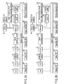
FIG. 2A is a block diagram illustrating a schematic constitution of the electronic camera according to a modified example 1 of a modification of the present invention; -
FIG. 2B is a block diagram illustrating a schematic constitution of the electronic camera according to a modified example 2 of a modification of the present invention; -
FIG. 3 is a rear view viewed from a rear side of the electronic camera illustrating the constitution of the electronic camera according to a first embodiment of the present invention; -
FIG. 4 is a flowchart explaining an operation for checking a face image in the electronic camera according to the first embodiment of the present invention; -
FIG. 5 is a diagram illustrating examples of object images and regions of interest to be displayed on aliquid crystal display 60 in a display device ofFIG. 1 ; -
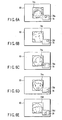
FIG. 6A is a diagram illustrating an example of superimposed display of the enlarged image in a region ofinterest 72b ofFIG. 5 , an image frame and a display region; -
FIG. 6B is a diagram illustrating an example of a superimposed display of the enlarged image in a region ofinterest 72c ofFIG. 5 , an image frame and a display region; -
FIG. 6C is a diagram illustrating an example of superimposed display of the enlarged image in a region ofinterest 72a ofFIG. 5 , an image frame and a display region; -
FIG. 6D is a diagram illustrating an example of superimposed display of the enlarged image in a region ofinterest 72e ofFIG. 5 , an image frame and a display region; -
FIG. 6E is a diagram illustrating an example of superimposed display of the enlarged image in a region ofinterest 72d ofFIG. 5 , an image frame and a display region; -
FIG. 7 is a diagram illustrating a constitutional example of an object switching button according to a first modified example in the first embodiment of the present invention; -
FIG. 8 is a rear view viewed from the rear side of the electronic camera illustrating a constitution of the electronic camera according to the first modified example in the first embodiment of the present invention; -
FIG. 9 is a flowchart explaining an operation for checking a face image in the electronic camera according to the first modified example in the first embodiment of the present invention; -
FIG. 10 is a flowchart explaining the operation for checking a face image in the electronic camera according to a second modified example in the first embodiment of the present invention; -
FIG. 11 is a diagram illustrating an example where an object image obtained by the electronic camera is divided into small regions according to the second modified example in the first embodiment of the present invention; -
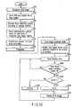
FIG. 12 is a flowchart explaining the operation for checking a face image in the electronic camera according to a second embodiment of the present invention; -
FIG. 13 is a flowchart explaining the operation for checking the face image in the electronic camera according to a third embodiment of the present invention; and -
FIG. 14 is a flowchart explaining the operation for checking the face image in the electronic camera according to a modified example in the third embodiment of the present invention. - Best Mode for Carrying Out the Invention Embodiments of the present invention will be explained below with reference to the drawings.
-
FIG. 1 is a block diagram illustrating a schematic constitution of an electronic camera according to a first embodiment of the present invention. - In
FIG. 1 , asystem controller 10 is control means for controlling a control operation of the entire electronic camera, and is composed of a CPU or the like. Thesystem controller 10 is connected to a photographinglens 12 which is built into a lens barrel, not shown, aCCD 14 as an imaging element which images an optical image of an object via the photographinglens 12, animaging circuit 16 which converts the optical image captured by theCCD 14 into an electrical signal, an analog-to-digital converter 18, asignal processing circuit 20 and amemory 22. Further, thesystem controller 10 is connected to adistance measuring unit 34, a release switch (SW) 38, a menu switch (SW) 40, an image operating switch (SW) 42 and an operating switch (SW) 44. Thememory 22 is connected to astorage media 30 via a compressingcircuit 28 and to adisplay device 32 via adisplay memory 26. - The
distance measuring unit 34 is for obtaining a focussing position of an object (not shown) according to automatic measurement of distance. Therelease switch 38 corresponds to arelease button 52, mentioned later, for starting a photographing operation, and has a two-tiered constitution including a first release switch and a second release switch. When therelease button 52 is half-pressed down, the first release switch is in an ON state so that photographing preparing operations such as a photometry process and a distance measuring process are performed. When therelease button 52 is fully pressed down, the second release switch is turned on, so that an exposing operation is executed. - The
menu switch 40 is for operating various functions of the electronic camera. Theimage operating switch 42 is for switching an image to be displayed on thedisplay device 32. Theimage operating switch 42 is composed of a face imagebrowsing mode switch 58, animage switching button 60, anobject switching button 62 and the like, mentioned later. When these buttons are operated, an image to be displayed on the display surface of thedisplay device 32 is switched. The operatingswitch 44 corresponds to an operating button such as a power switch necessary for operating the camera. - The photographing
lens 12, theCCD 14, theimaging circuit 16, the analog-to-digital converter 18, thesignal processing circuit 20, thememory 22, thedisplay memory 26, the compressingcircuit 28, thestorage media 30, thedisplay device 32, thedistance measuring unit 34 are well known. For this reason, their details are omitted. - In such a constitution, an optical image of an object which passes through the photographing
lens 12 is converted into an electric signal by theCCD 14, and the electric signal is converted into an analog image signal by theimaging circuit 16. The analog image signal is converted into a digital image signal (hereinafter, "image information") by the analog-to-digital converter 18, and a process for converting color information of the image information, a pixel count converting process, a process for recognizing a face image and the like are executed in thesignal processing circuit 20. The image information which is subject to various image processes by thesignal processing circuit 20 is stored in thenonvolatile memory 22. Thememory 22 is composed of a high-speed storage unit, for example, SDRAM, and is used also as a work area for an image process, mentioned later. - The image information which is once stored in the
memory 22 is compressed into JPEG format, for example, by the compressingcircuit 28, and is stored in thestorage media 30 such as smart media (registered trademark). The image signal which is subject to the signal process is transferred from thememory 22 to thedisplay memory 26, and is displayed on thedisplay device 32 via a driving circuit, not shown. - When the image stored in the
storage media 30 is displayed, the stored image is decompressed by an expanding circuit, not shown, and after the image is subject to a predetermined image process by thesignal processing circuit 20, the image is displayed on thedisplay device 32 similarly to the photographing case. -
FIG. 3 is a rear view viewed from a rear side of the electronic camera illustrating a constitution of the electronic camera according to the first embodiment of the present invention. - In
FIG. 3 , therelease button 52 corresponding to therelease switch 38, and a photographingmode switch 54 for selecting a photographing mode are provided above a cameramain body 50a. Aliquid crystal display 60 as thedisplay device 32 is provided to an approximately center of a rear side of the cameramain body 50a. - A face image
browsing mode switch 62 for operating a face image browsing mode whose details are mentioned later is provided to the left side of theliquid crystal display 60. On the other hand, the right side of theliquid crystal display 60 is provided with animage switching button 64 for switching one frame of image currently displayed on theliquid crystal display 60, and anobject switching button 66 for switching to select an object displayed on theliquid crystal display 60. In this case, theimage switching button 64 is composed of aswitching button 64a for switching an image into an image one frame after the currently displayed image so as to display it, and aswitching button 64b for switching an image into an image one frame before the current displayed image so as to display it. - With reference to the flowchart in
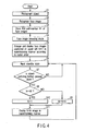
FIG. 4 , an operation for checking a face image in the electronic camera according to the first embodiment is explained below. - When a power switch, not shown, is turned on, an object is photographed in step S1. In this case, as shown in
FIG. 5 , a plurality (in this case, five) ofpeople 70a to 70e are present in an object image obtained by photographing objects. When the objects are photographed in step S1, the image is transmitted from theCCD 14 via theimaging circuit 16 and the analog-to-digital converter 18 to thesignal processing circuit 20 as mentioned above. Thesignal processing circuit 20 then executes a color information converting process, a pixel count changing process, a face image recognizing process and the like in step S2. The face image recognizing process is well known, and since its detail is described in, for example, Jpn. Pat. Appln. KOKAI Publication No.2004-240829 - The
signal processing circuit 20 determines regions of interest (ROI) as regions according to the face images in step S3. The regions of interest and the number of the objects' faces N1 (=5) are stored in thememory 22. For example, an image shown inFIG. 5 is displayed on the liquid crystal display 50. In this case, the region of interest for the face image includes five regions designated by 72a to 72e correspondingly topeople 70a to 70e. The sizes of the region of interest, coordinate start positions and the like of these regions are stored in thememory 22. Also image information about results of the color information converting process and the image count converting process are stored in thememory 22. - The face image
browsing mode switch 62 is pressed down in step S4, and the face image browsing mode is executed according to the following steps. The face image in the region of interest positioned on the upper left portion of the screen is enlarged to be displayed in the raster order based on the contents in thememory 22 in step S5. "1" is set as the face image N. In this case, as shown inFIG. 5 , the region ofinterest 72b having the higher order in the raster order, namely, the face image of theperson 70b is displayed as anenlarged image 74b on theliquid crystal display 60 as shown inFIG. 6A . - At this time, a position on the screen of
FIG. 5 , which corresponds to the region ofinterest 72b to be displayed as theenlarged image 74b, is displayed on theliquid crystal display 60 in a superimposing manner. That is to say, ascreen frame 76 displayed in the superimposing manner shows the entire screen of theliquid crystal display 60. Adisplay region 78a in thescreen frame 76 corresponds to the region ofinterest 72b inFIG. 5 . A user, therefore, can check theenlarged image 74b shown inFIG. 6A and simultaneously the position on the screen where theenlarged image 74b is present on theliquid crystal display 60. - Thereafter, the camera is in an input standby state in step S6. A state of the
object switching button 66 is detected in step S7. When theobject switching button 66 is pressed down, the sequence goes to step S8, but when it is not pressed down, the sequence goes to step S6. That is to say, steps S6 and S7 are repeated until theobject switching button 66 is pressed down. - On the other hand, when the detection is made in step S7 that the
object switching button 66 is pressed down, the sequence goes to step S8, so that a determination is made whether the face image N set in step S5 is N1. In this case, since "1" is set as N in step S5 and "5" is set as the number of the object's faces N1 in step S3, the sequence goes to step S9 so that N is incremented. - The region of interest related to the face image of the N-numbered object is enlarged to be displayed on the
liquid crystal display 60 in step S11. In this case, since incrementing is carried out in step S9, the face image of N=2 is displayed. That is to say, as shown inFIG. 5 , the region ofinterest 72c on the second-highest order of the raster order, namely, the face image of theperson 70c is displayed as anenlarged image 74c on theliquid crystal display 60 as shown inFIG. 6B . At the same time, adisplay region 78c in thescreen frame 76 corresponding to the region ofinterest 72c inFIG. 5 is displayed on theliquid crystal display 60 in the superimposing manner. Thereafter, the sequence goes to step S6 so that the camera is in the input standby state. - The processing operations in steps S6 to S9 and S11 are repeated until N = N1 is established in step S8. That is to say, in the first embodiment, the
enlarged image 74b, thescreen frame 76 and thedisplay region 78a (seeFIG. 6A ) are displayed on theliquid crystal display 60 firstly. Thereafter, every time when theobject switching button 66 is pressed down, theenlarged image 74c, thescreen frame 76 and adisplay region 78c (seeFIG. 6B ) are displayed, anenlarged image 74a, thescreen frame 76 and adisplay region 78a (seeFIG. 6C ) are displayed, anenlarged image 74e, thescreen frame 76 and adisplay region 78e (seeFIG. 6D ) are displayed, and anenlarged image 74d, thescreen frame 76 and adisplay region 78d (seeFIG. 6E ) are displayed sequentially on theliquid crystal display 60. - When N = N1 is established in step S8, the sequence goes to step S10, and "1" is set as N is again. This is because the number of the face images of the objects (people) is five in this embodiment, and when the
object switching button 66 is pressed down four times, the face image of the fifth person is enlarged to be displayed. Therefore, when theobject switching button 66 is pressed down five times, the firstenlarged screen 74b is displayed next, and the face image N is again set to "1" in step S10. As a result, theenlarged image 74b of the N-th object, namely, the first object, thescreen frame 76 and thedisplay region 78a are displayed on theliquid crystal display 60 at next step S11. - Since reducing and enlarging processes are executed on image information in the respective regions of interest, the
enlarged images 74a to 74e are displayed with the approximately same size on theliquid crystal display 60. - According to the first embodiment, even in the case where a plurality of faces are photographed as objects, the
object switching button 66 is operated, and a plurality of face images are selectively switched so as to be capable of being displayed in the approximately same size. Therefore, the respective faces and a good photographed state are easily checked. - A position on the photographed image, in which the enlarged image currently displayed on the
liquid crystal display 60 is present, can be easily checked by thescreen frame 76 and thedisplay regions 78a to 78e to be displayed on theliquid crystal display 60. - In the first embodiment, the sizes of the region of interest and the coordinate start positions are stored, but the present invention is not limited to this, and thus the center point of the region of interest may be stored. In this case, the raster order is different from the display order in
FIG. 6 . - In the case where the photographing mode for user's photographing and the face image browsing mode for browsing the face images in the
display device 32 are provided, the processes after step S2 can be executed under the condition that the face image browsing mode is specified by the user. In this case, when a detection is made that the face imagebrowsing mode switch 62 is operated, a detection may be made that the face image browsing mode is specified by the user. Step S4 is omitted. - As shown in
FIG. 2A , in the case of a modified example where thesignal processing circuit 46 is added to the constitution, an object image can be selected from a plurality of images saved in thestorage media 30 at a reproducing mode for user's browsing of a photographed object image. That is to say, the object image is selected by the user at the reproducing mode, and thesignal processing circuit 46 executes the processes after step S2 on the object image selected instead of the object image from the analog-to-digital converter 18 under the condition that the face image browsing mode is specified by the user. In this case, step S4 is omitted, and the user's selection of the object image is accepted by the operation of theimage switching button 64, and the specifying of the face image browsing mode can be accepted by the operation of the face imagebrowsing mode switch 62. - The electronic camera can be constituted like the modified example shown in
FIG. 2B . In the example ofFIG. 2B , after thesignal processing circuit 20 executes the color information converting process, the pixel count converting process and the like on the image information (object image) from the analog-to-digital converter 18, the image information is stored in thememory 22. In the example ofFIG. 2B , the image information stored in thememory 22 is transmitted to the compressingcircuit 28 so as to be compressed as mentioned above and is transmitted to thesignal processing circuit 46 for recognizing the face images. The processes after step S2 are executed on the image information. In this case, step S4 is omitted. - When the face image browsing mode switch 36 is pressed down in step S6, the photographing mode or the reproducing mode is selected.
- A first modified example in the first embodiment of the present invention is explained below.
- In the first embodiment described above, only one
object switching button 66 is provided to the cameramain body 50a, and every time when theobject switching button 66 is pressed down, the enlarged images are switched to be displayed sequentially according to the raster order. In the first modified example of the first embodiment, four object switching buttons are provided, and desired enlarged images can be switched to be displayed according to the user's selection. - The first modified example of the first embodiment is explained below.
-
FIG. 7 is a diagram illustrating a constitutional example of the object switching button according to the first modified example of the first embodiment. - In
FIG. 7 , theobject switching button 80 is composed of a switching button (R) 80a for switching an image into an image one frame after so as to display it, a switching button (L) 80b for switching an image into an image one frame before so as to display it, a switching button (U) 80c for enlarging an image, and a switching button (D) 80d for reducing an image. - The camera
main body 50b provided with theobject switching button 80 is constituted as shown inFIG. 8 . In the first modified example, since the part of the constitution other than theobject switching buttons 80 is the same as that in the first embodiment, like members are designated by like reference numerals and the explanation thereof is omitted. -
FIG. 9 is a flowchart explaining the operation for checking a face image in the electronic camera according to the first modified example in the first embodiment. The processing operations in steps S21 to S25 are similar to those in the explanation related to steps S1 to S5 in the flowchart ofFIG. 4 . - When the power switch, not shown,'is turned on, objects are photographed in step S21. The well-known face image recognizing process is executed in step S22. The regions of interest (ROI) of face images and the number of objects' faces N1 on the screen are stored in the
memory 22 in step S23. The face image browsing mode switch 36 is pressed down in step S24, so that the face image browsing mode is executed. The face image in an upper left part of the screen is enlarged and displayed in the raster order in step S25, so that.the face image N is set to "1". - The camera is in the input standby state in step S26, and a button of the
object switching buttons 80 which is pressed down is detected. That is to say, when the object switching button (L) 80b is pressed down, the sequence goes to step S27, and when the object switching button (R) 80a is pressed down, the sequence goes to step S31. When the object switching button (U) 80c is pressed down, the sequence goes to step S36, and when the object switching button (D) 80d is pressed down, the sequence goes to step S90. - In the case where the object switching button (L) 80b is pressed down in step S27, a determination is made in step S28 whether the face image N set in step S25 is N1. When N is "1", the sequence goes to step S30, and the face image N = 1 is set. Further, the sequence goes to step S35, and the region of interest relating to the image face of the first object is enlarged to be displayed on the
liquid crystal display 60. - On the other hand, when N is not "1" in step S28, the sequence goes to step S29, and N is decremented. As mentioned later, this is executed in order to display an face image of the last object in the case where the face images of the second and after objects are displayed by the object switching button (R) 80a. As a result, for example, the
enlarged image 74c shown inFIG. 6B is switched into theenlarged image 74b shown inFIG. 6A . - In the case where the object switching button (R) 80a is pressed down in step S31, a determination is made in step S32 whether the face image N is equal to the number N1 of the objects' faces on the screen set in step S25. When N is not equal to N1, the sequence goes to step S33, so that N is incremented. The incremented face image of the N-th object is enlarged to be displayed on the
liquid crystal display 60 in step S35. - On the other hand, when N = N1 is established in step S32, the sequence goes to step S34, N is again set to "1". This is because similarly to the first embodiment, when the display reaches the number of the face images of the objects set in steps S23, the display returns to the face image of the first object. Therefore, at next step S35, the face image of the N-th, namely, the first object is enlarged to be displayed on the
liquid crystal display 60. - After the enlarged display in step S35, the sequence goes to step S26 so that the camera is in the input standby state.
- In the case where the object switching button (U) 80c is pressed down in step S36 in the input standby state in step S26, the sequence goes to step S37 so that a current enlargement scale X is compared with a predetermined maximum threshold value of the enlargement scale Thr_1. When the enlargement scale X is not more than the predetermined maximum threshold value Thr_1 of the enlargement scale X, the sequence goes to step S38 so that the current enlargement scale X is set to a predetermined scale A (for example, × 1.1). The sequence then goes to step S44, and the face image displayed in step S25 or S35 is displayed at the enlargement scale X set in step S38 on the
liquid crystal display 35. - On the other hand, when the enlargement scale X exceeds the predetermined maximum threshold value Thr_1 of the enlargement scale in step S37, the sequence goes to step S39, so that the maximum threshold value of the predetermined enlargement Thr_1 is set as the current enlargement scale X. The sequence then goes to step S44, and the face image displayed in step S25 or S35 is displayed at the enlargement scale X set in step S38 on the
liquid crystal display 60. - In the case where the object switching button (D) 80d is pressed down in step S40 in the input standby state in step S26, the sequence goes to step S41 so that the current enlargement scale X is compared with a predetermined minimum threshold value of the enlargement scale Thr_2. When the enlargement scale X is not less than the predetermined minimum threshold value of the enlargement scale Thr_2, the sequence goes to step S42 so that the current enlargement scale X is reduced to a predetermined scale B (for example, B = × 1/A). The sequence then goes to step S44, and the face image displayed in step S25 or S35 is displayed at the enlargement scale X set in step S42 on the
liquid crystal display 60. - On the other hand, when the enlargement scale X is less than the predetermined minimum threshold value of the enlargement scale Thr_2 in step S41, the sequence goes to step S43, and the predetermined minimum threshold value of the enlargement scale Thr_2 is set as the current enlargement scale X. The sequence goes to step S44, and the face image to be displayed in step S25 or S35 is displayed at the enlargement scale X set in step S43 on the
liquid crystal display 60. - After the enlarged display in step S44, the sequence goes to step S26, and the camera is in the input standby state.
- According to the first modified example in the first embodiment, similarly to the first embodiment described above, even in the case where a plurality of faces are photographed as objects, the
object switching buttons 80a to 80d are operated so that the plural face images can be selectively switched so as to be displayed with the approximately same size, and the face images can be changed into desired sizes so as to be displayed. - In the first modified example, it goes without saying that the screen frames and the display regions can be displayed on the liquid crystal display in the superimposing manner. A position on the photographed image where the enlarged image displayed on the
liquid crystal display 60 is present can be easily checked by thedisplay regions 78a to 78e. - In the first modified example, the size of the region of interest and the coordinate start position are stored, but the center point of the range of interest, a point on the upper left of the region of interest or the like may be stored as the raster order. In this case, the raster order is different from the display order shown in
FIG. 6 . - A second modified example in the first embodiment of the present invention is explained below.
- In the first embodiment and the first modified example, the face images on the left part of the screen are sequentially enlarged to be displayed in the raster order. When, however, the face images are tried to be displayed precisely according to the raster order, this makes a difference between the raster order and the user's perception of the order from upper left to lower right. For this reason, in the second modified example, an image on the monitor screen is divided into a plurality of divided regions, and the images on the regions are displayed according to the divided order.
- The operation for checking face images in the electronic camera according to the second modified example in the first embodiment of the present invention is explained with reference to the flowchart in
FIG. 10 . - In the second modified example in the first embodiment, since the constitution and the basic operation of the electronic camera are the same as those in the first embodiment, like members are designated by like numbers and the explanation thereof is omitted.
- When the power switch, not shown, is turned on, objects are photographed in step S51. In this case, a plurality of people (in this case, five) 70a to 70e are present as the objects as shown in
FIG. 11 . When the objects are photographed in step S51, the face image recognizing process is executed in step S52. Similarly to step S2, the processes after step S52 may be executed after specifying of the face image browsing mode is accepted. - Indexes of the face images, the region of interest (ROI) and the number N1 (=5) of the objects' faces on the screen are stored in the
memory 22 in step S53. For example, an image shown inFIG. 11 is displayed on theliquid crystal display 60. In this case, the five regions of interest for the face images are designated by 72a to 72e forrespective people 70a to 70e. Information about them are stored. Further, the object image is divided into divided regions with indexes in step S54. In this case, the object image is divided into nine divided regions (1) 601 to (9) 609 as shown inFIG. 11 . The divided regions (1) to (9) indicate thenumbers 1 to 9 given to the respective regions inFIG. 11 . - In the case where the respective regions divided in step S54 include start positions of the regions of interest for the face images, respectively, the indexes of the divided regions and the indexes of the face images are stored in step S55. In the case where one divided region includes two or more face images, a face image where the start position of the region of interest is smaller has small index. For example, when the center points of the regions of interest are expressed by the raster order, in the case of the object image shown in
FIG. 11 , the face images of twopeople interest 72b whose start position is smaller has an index smaller than that of the region ofinterest 72c. - The face image
browsing mode switch 62 is pressed down in step S56, so that the face image browsing mode is executed. At next step S57, an image, where the index number of its divided region and the index number of its face image are the smallest, is enlarged to be displayed, and the face image N is set to "1". Thereafter, the sequence goes to step S58, and the camera is in the input standby state. Since the respective processing operations in steps S58 to S63 are similar to steps S6 to S11 in the flowchart ofFIG. 4 , corresponding step numbers are referred to and the explanation thereof is omitted. - According to the second modified example, in the case where, for example, the
people 70a to 70e are present in the positions as shown inFIG. 11 , the enlarged images in the regions ofinterest - Also in the second modified example, the screen frame and the display region can be displayed on the liquid crystal display in the superimposing manner. Further, in the second modified example, as to the raster order, the center point of the region of interest is used, but an upper left point of the region of interest or the like may be used.
- In the second modified example, the
object switching button 66 is operated to switch the image of the object's face to another, as explained above. Instead, fourobject switching buttons 80a to 80d may of course be used to switch the image, as in the fist modified example described above. - A second embodiment of the present invention is explained below.
- In the first embodiment, the enlarged images are displayed in the raster order, but in the second embodiment, evaluated values of recognition of the objects' face images are calculated, so that the display of the enlarged images is switched according to the order of the evaluated values.
- In the second embodiment described below, since the constitution and the basic operation of the electronic camera are the same as those in the first embodiment described above, like members are designate by like reference numerals and the explanation thereof is omitted.
- The operation for checking face images in the electronic camera according to the second embodiment of the present invention is explained below with reference to the flowchart in
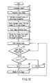
FIG. 12 . - When the power switch, not shown, is turned on, the objects are photographed in step S71, and face images are recognized in step S72. The evaluated values of the face image recognition are calculated in step S73. Similarly to the case in step S2, the processes after step S72 may be executed after the specifying of the face image browsing mode is accepted.
- The evaluated values are determined by the degree of similarity which is also called a matching degree with respect to templates having predetermined facial shape in the recognizing method for recognizing a person's face from an image. In the face image recognizing method utilizing the matching degree, plural types of face-shaped templates are prepared, the matching degree between the templates and an image is calculated according to normalization intercorrelation, and a template having the highest matching degree is selected. When the highest matching degree is not less than a predetermined threshold value, a region in the selected template is determined as a face candidate region. Such a recognizing method is disclosed in Jpn. Pat. Appln. KOKAI Publication No.
2004-240829 - In addition to the method of calculating the matching degree between face shape and a template, for example, an eye region may be extracted so that a face region is recognized in the face candidate region, or a mouth, hair, a neck and the like are extracted from eye position information so that a face region may be recognized.
- The evaluated values of the face image, the regions of interest and the number N1 (=5) of the regions of interest are stored in the
memory 22 in step S74. For example, in the case where the image shown inFIG. 5 is displayed on theliquid crystal display 60, the regions of interest for the face image include the five regions ofinterest 72a to 72e forrespective people 70a to 70e. When the face imagebrowsing mode switch 62 is pressed down, the face image browsing mode is executed in step S75. The face image with the highest evaluated value of the face image recognition calculated in step S73 is enlarged to be displayed in step S76, and the face image N is set to 1. In this case, the face images N having the higher evaluated values calculated in step S73 are set to "1", "2", ... in this order. - Thereafter, the camera is in the input standby state in step S77. The state of the
object switching button 66 is detected in step S78. The processes in steps S77 and S78 are repeated until theobject switching button 66 is pressed down. In the case where the pressing-down of theobject switching button 66 is detected in step S78, the sequence goes to step S79 so that a determination is made whether the set face image N set in step S76 is N1. - The sequence goes to step S80 and the N is incremented until face image N is equal to N1. The region of interest relating to the object's face image with N-th evaluated value is enlarged to be displayed on the
liquid crystal display 60 in step S82. On the other hand, when the face image N is equal to N1 in step S79, the sequence goes to step S81, and the face image N is set to "1" so that the first face image is displayed. Thereafter, when the original image is display in step S82, the camera is again in the input standby state in step S77. - According to the second embodiment, since the face images are switched to be displayed sequentially in decreasing order of the evaluated values of the face image recognition, the high-precision face image can be checked for the faces and a good photographed state.
- Also in the second embodiment, it goes without saying that the screen frame and the display region can be displayed on the liquid crystal display in the superimposing manner.
- In the second embodiment, the face images are displayed on the liquid crystal display sequentially in decreasing order of the evaluated values of the face image recognition, but the present invention is not limited to this, and thus they may be displayed in increasing order of the evaluated values.
- In the second embodiment, the face images are switched by the
object switching button 66, but the present invention is not limited to this, and thus the fourobject switching buttons 80a to 80d may be used like the first modified example of the first embodiment. - As to the evaluated value of the face image recognition, for example, an attention is paid to eye portions of objects, and eye shutting states are evaluated by the method disclosed in Jpn. Pat. Appln. KOKAI Publication No.
2003-287784 - A third embodiment of the present invention is explained below.
- In the third embodiment, the enlarged face images are displayed in such a manner that focus estimated positions are switched in order of being closer to the camera in cooperation with focus detection.
- In the third embodiment, since the constitution and the basic operation of the electronic camera are the same as those in the first and the second embodiments, like members are designated by like reference numerals and the explanation thereof is omitted.
- The operation for checking face images in the electronic camera according to the third embodiment of the present invention is explained below with reference to a flowchart in
FIG. 13 . - When the power switch, not shown, is turned on, the well-known face image recognizing process is executed in step S91. The regions of interest and the number of regions of interest N1 on the face images are stored in step S92. The
distance measuring unit 34 executes a focus detecting process according to a well-known contrast method in step S93. The contrast method is disclosed in, for example, Japanese Patent Publication No.2507144 - An estimated lens position (step number) of the photographing
lens 12 where the focus is the best, namely, the evaluated value is the largest in the regions of interest on the images is stored in thememory 22 in step S94. The focus position is controlled as the lens position to be the best focus in step S95, and photographing is carried out in step S96. - After photographing, when the face image
browsing mode switch 62 is pressed down in step S97, the face image browsing mode is executed. The region of interest on the object's face image whose focus estimated position obtained in step S94 is the closest to the camera is enlarged to be displayed in step S98, and the face image N is set to "1". In this case, as the distance from the camera is greater, the face images N are "1", "2", ... according to the focus detecting process in step S93. - Thereafter, the camera is in the input standby state in step S99. The state of the
object switching button 38 is detected in step S100. The processes in steps S99 and S100 are repeated until theobject switching button 38 is pressed down. When the pressing-down of theobject switching button 66 is detected in step S100, the sequence goes to step S101, and a determination is made whether the face image N sent in step S98 is N1. - The sequence goes to step S102 and N is incremented until the face image N is equal to N1. The face image of the object which is the N-th closest to the camera is enlarged to be displayed on the
liquid crystal display 60 in step S104. On the other hand, when the face image N is equal to N1 in step S101, the sequence goes to step S103, and the face image N is set to "1" so that the first face image is displayed. Thereafter, when the original image is displayed in step S104, the camera is again in the input standby state of step S99. - According to the third embodiment, since the objects are switched to be displayed sequentially in order such that the focus estimated positions are closer to the camera, the faces and a good photographed state of the faces can be checked easily from the face image.
- Also in the third embodiment, it goes without saying that the screen frame and the display region can be displayed on the liquid crystal display in the superimposing manner.
- In the third embodiment, the face images are displayed in the order such that the focus estimated positions are closer to the camera, but on the contrary the face images may be displayed according to the order such that the objects are farther from the camera.
- Also in the third embodiment, the face images are switched by the
object switching button 66, but the present invention is not limited to this, and thus the fourobject switching buttons 80a to 80d may be used like the first modified example of the first embodiment. - A modified example of the third embodiment is explained below.
- In the third embodiment, the order of the face images of the objects is determined according to their distances from the camera, but in the modified example of the third embodiment, the order of the face images of objects is determined according to the order such that object is closer to their best focus positions of the camera.
- In the modified example of the third embodiment described above, since the constitution and the basic operation of the electric camera are the same as those in the first to the third embodiments, like members are designated by like reference numerals and the explanation thereof is omitted.
- The operation for checking the face images in the electronic camera according to the modified example in the third embodiment of the present invention is explained below with reference to a flowchart in
FIG. 14 . Since the processing operations in steps S111 to S117 in the flowchart ofFIG. 14 are the same as those in steps S91 to S97 in the flowchart ofFIG. 13 , only corresponding step numbers are referred to and the explanation thereof is omitted. - The region of interest relating to the object's face image whose focus estimated position obtained in step S114 is the closest to the best focus is enlarged to be displayed in step S118, and the face image N is set to "1". In this case, the face images N are set to "1", "2", ... in this order such that the objects are farther from the best focus position according to the focus detecting process in step S93.
- Thereafter, the camera is in the input standby state in step S119. The state of the
object switching button 66 is detected in step S120. The processes in steps S119 and S120 are repeated until theobject switching button 66 is pressed down. When the pressing-down of theobject switching button 66 is detected in step S120, the sequence goes to step S121 so that a determination is made whether the face image N set in step S118 is N1. - The sequence goes to step S122 and N is incremented until the face image N is equal to N1. The face image of the object in the focus position which is the N-th closest from the best focus position is enlarged to be displayed on the
liquid crystal display 60 in step S124. On the other hand, when the face image N is equal to N1 in step S121, the sequence goes to step S123, and the face image N is set to "1" so that the first face image is displayed. Thereafter, when the original image is displayed in step S124, the camera is again in input standby state of step S119. - According to the modified example of the third embodiment, since the face images are switched to be displayed sequentially in the order such that the focus estimated positions are farther from the best focus position of the camera, the faces and the good photographed state can be checked easily on the face images.
- Also in the modified example of the third embodiment, it goes without saying that the screen frame and the display region can be displayed on the liquid crystal display in the superimposing manner.
- In the modified example of the third embodiment, the face images are displayed in the order such that the focus estimated positions are separated from the best focus position of the camera, but on the contrary the face images of the objects may be displayed in the order such that the focus estimated positions approach the best focus position.
- Also in the modified example of the third embodiment, the face images are switched by the
object switching button 66, but the present invention is not limited to this, and the fourobject switching buttons 80a to 80d may be used similarly to the first modified example of the first embodiment. - The embodiments of the present invention have been explained above, but in addition to the above embodiments, the present invention can be variously modified without departing from the scope of the present invention.
- According to the present invention, the electronic camera, which has a simple interface for checking faces and a good photographed state when a plurality of faces are photographed as objects, can be provided.
- Additional advantages and modifications will readily occur to those skilled in the art. Therefore, the invention in its broader aspects is not limited to the specific details and representative embodiments shown and described herein. Accordingly, various modifications may be made without departing from the scope of the general inventive concept as defined by the appended claims and their equivalents.
Claims (9)
- An electronic camera comprising:an extracting section which is adapted to extract a plurality of regions of interest including face images from an object image to be shot;a distance estimating section which is adapted to obtain a plurality of focus estimated lens positions corresponding to in focus conditions of the plurality of the regions of interest extracted by the extracting section prior to shooting;a display order determining section which is adapted to determine an order of displaying the plurality of the regions of interest based on the plurality of the focus estimated lens positions obtained by the distance estimating section; anda display section which is adapted to display the regions of interest based on the order of displaying, wherein the regions of interest are enlarged.
- The electronic camera according to claim 1, wherein:the distance estimating section is adapted to obtain a best focus lens position of the electronic camera for shooting; andthe display order determining section is adapted to determine the order of displaying the plurality of the regions of interest on the display section based on a relationship between the best focus lens position and the focus estimated lens position of the plurality of the regions of interest.
- The electronic camera according to claim 2, wherein the display order determining section is adapted to determine the order of displaying to display first a region of interest of which focus estimated lens position is closest to the best focus lens position on the display section from the plurality of the regions of interest.
- The electronic camera according to claim 2, wherein the display order determining section is adapted to determine the order of displaying to display the plurality of the regions of interest in increasing order of differences between the best focus lens position and the focus estimated lens position of the regions of interest on the display section.
- The electronic camera according to claim 1, wherein the display order determining section is adapted to determine the order of displaying to display the plurality of the regions of interest in an order the closer distances estimated by the distance estimating section of the regions of interest are closer to the electronic camera the earlier displayed on the display section.
- The electronic camera according to claim 1, further comprising
a changing section which is adapted to change a size of the region of interest including the face images to be displayed on the display section into a desired size. - The electronic camera according to claim 1, wherein the display section is adapted to display the images of the region of interest including the face images positioned by superimposing them on the display section.
- An image processing method comprising:extracting a plurality of regions of interest including face images from objected images to be shot;obtaining a plurality of focus estimated lens positions corresponding to each of the plurality of the extracted regions of interest; anddetermining an order of displaying the plurality of the regions of interest based on the plurality of the obtained focus estimated lens positions.
- An image processing program run on a computer comprising:extracting a plurality of regions of interest including face images from objected images to be shot;obtaining a plurality of focus estimated lens positions corresponding to each of the plurality of the extracted regions of interest; anddetermining an order of displaying the plurality of the regions of interest based on the plurality of the obtained focus estimated lens positions.
Priority Applications (1)
| Application Number | Priority Date | Filing Date | Title |
|---|---|---|---|
| EP11009851A EP2448247A1 (en) | 2005-11-02 | 2006-10-23 | An image processor for electronic camera |
Applications Claiming Priority (2)
| Application Number | Priority Date | Filing Date | Title |
|---|---|---|---|
| JP2005319868 | 2005-11-02 | ||
| PCT/JP2006/321582 WO2007052572A1 (en) | 2005-11-02 | 2006-10-23 | Electronic camera |
Related Child Applications (1)
| Application Number | Title | Priority Date | Filing Date |
|---|---|---|---|
| EP11009851A Division-Into EP2448247A1 (en) | 2005-11-02 | 2006-10-23 | An image processor for electronic camera |
Publications (3)
| Publication Number | Publication Date |
|---|---|
| EP1949670A1 EP1949670A1 (en) | 2008-07-30 |
| EP1949670A4 EP1949670A4 (en) | 2009-11-04 |
| EP1949670B1 true EP1949670B1 (en) | 2012-09-12 |
Family
ID=37996432
Family Applications (2)
| Application Number | Title | Priority Date | Filing Date |
|---|---|---|---|
| EP06822543A Expired - Fee Related EP1949670B1 (en) | 2005-11-02 | 2006-10-23 | Electronic camera |
| EP11009851A Withdrawn EP2448247A1 (en) | 2005-11-02 | 2006-10-23 | An image processor for electronic camera |
Family Applications After (1)
| Application Number | Title | Priority Date | Filing Date |
|---|---|---|---|
| EP11009851A Withdrawn EP2448247A1 (en) | 2005-11-02 | 2006-10-23 | An image processor for electronic camera |
Country Status (5)
| Country | Link |
|---|---|
| US (2) | US7643742B2 (en) |
| EP (2) | EP1949670B1 (en) |
| JP (1) | JP4832518B2 (en) |
| CN (2) | CN101300826A (en) |
| WO (1) | WO2007052572A1 (en) |
Families Citing this family (51)
| Publication number | Priority date | Publication date | Assignee | Title |
|---|---|---|---|---|
| CN101300826A (en) * | 2005-11-02 | 2008-11-05 | 奥林巴斯株式会社 | Electric camera |
| JP2007299339A (en) * | 2006-05-08 | 2007-11-15 | Fujifilm Corp | Image reproducing device, method and program |
| US8615112B2 (en) * | 2007-03-30 | 2013-12-24 | Casio Computer Co., Ltd. | Image pickup apparatus equipped with face-recognition function |
| JP4958659B2 (en) * | 2007-07-03 | 2012-06-20 | キヤノン株式会社 | Image display control device, image display control method, program, and recording medium |
| JP4961282B2 (en) * | 2007-07-03 | 2012-06-27 | キヤノン株式会社 | Display control apparatus and control method thereof |
| JP5053731B2 (en) * | 2007-07-03 | 2012-10-17 | キヤノン株式会社 | Image display control device, image display control method, program, and recording medium |
| US20100283843A1 (en) * | 2007-07-17 | 2010-11-11 | Yang Cai | Multiple resolution video network with eye tracking based control |
| US8497928B2 (en) * | 2007-07-31 | 2013-07-30 | Palm, Inc. | Techniques to automatically focus a digital camera |
| JP2009044463A (en) * | 2007-08-08 | 2009-02-26 | Sanyo Electric Co Ltd | Electronic camera and field image reproduction device |
| KR101431535B1 (en) * | 2007-08-30 | 2014-08-19 | 삼성전자주식회사 | Apparatus and method for picturing image using function of face drecognition |
| KR20090083108A (en) * | 2008-01-29 | 2009-08-03 | 삼성전자주식회사 | A method of capturing image to add enlarged image of certain region to the captured image and an image capturing apparatus thereof |
| JP2009192949A (en) * | 2008-02-15 | 2009-08-27 | Sony Corp | Image processing apparatus, image processing method, and image processing system |
| JP5217505B2 (en) * | 2008-02-29 | 2013-06-19 | 富士通株式会社 | Image display processing apparatus, image display processing method, and image display processing program |
| JP5036612B2 (en) * | 2008-03-28 | 2012-09-26 | 三洋電機株式会社 | Imaging device |
| JP5429445B2 (en) * | 2008-04-08 | 2014-02-26 | 富士フイルム株式会社 | Image processing system, image processing method, and program |
| US20090303338A1 (en) * | 2008-06-06 | 2009-12-10 | Texas Instruments Incorporated | Detailed display of portion of interest of areas represented by image frames of a video signal |
| JP5067884B2 (en) * | 2008-08-07 | 2012-11-07 | キヤノン株式会社 | Imaging apparatus, control method thereof, and program |
| JP4702418B2 (en) * | 2008-09-09 | 2011-06-15 | カシオ計算機株式会社 | Imaging apparatus, image region existence determination method and program |
| KR101622599B1 (en) | 2009-01-07 | 2016-05-19 | 엘지전자 주식회사 | Mobile terminal and zoom image controlling method thereof |
| JP5267149B2 (en) * | 2009-01-19 | 2013-08-21 | ソニー株式会社 | Display control apparatus, display control method, and program |
| US20100214445A1 (en) * | 2009-02-20 | 2010-08-26 | Sony Ericsson Mobile Communications Ab | Image capturing method, image capturing apparatus, and computer program |
| CN101873426B (en) | 2009-04-25 | 2012-01-25 | 鸿富锦精密工业(深圳)有限公司 | Image preview system and image preview method thereof |
| JP5657235B2 (en) * | 2009-11-10 | 2015-01-21 | オリンパスイメージング株式会社 | Image capturing apparatus and image capturing method |
| TWI487370B (en) * | 2010-02-24 | 2015-06-01 | Ability Entpr Co Ltd | Method of zooming in on an image and a method of using a gui |
| EP2442550B1 (en) | 2010-10-14 | 2015-06-17 | Sony Corporation | Image capturing device, system and method |
| EP2442549B1 (en) | 2010-10-14 | 2015-10-14 | Sony Corporation | Image capturing device, system and method |
| JP2012186670A (en) * | 2011-03-07 | 2012-09-27 | Ricoh Co Ltd | Imaging device, imaging method, and imaging program |
| US8306267B1 (en) * | 2011-05-09 | 2012-11-06 | Google Inc. | Object tracking |
| US9715751B2 (en) | 2011-07-13 | 2017-07-25 | Apple Inc. | Zooming to faces depicted in images |
| JP5879831B2 (en) * | 2011-09-02 | 2016-03-08 | 株式会社ニコン | Electronic camera and image processing program |
| JP2013134574A (en) * | 2011-12-26 | 2013-07-08 | Canon Inc | Image data generation device, image data display system, and image data generation method |
| KR101231469B1 (en) | 2012-02-23 | 2013-02-07 | 인텔 코오퍼레이션 | Method, apparatusfor supporting image processing, and computer-readable recording medium for executing the method |
| KR102084582B1 (en) * | 2012-02-24 | 2020-03-04 | 삼성전자 주식회사 | Method and apparatus for adjusting the size of displayed object |
| CN102629140A (en) * | 2012-03-22 | 2012-08-08 | 圆展科技股份有限公司 | Camera positioning system and control method thereof |
| JP5941736B2 (en) * | 2012-04-10 | 2016-06-29 | オリンパス株式会社 | Photography equipment |
| US8854481B2 (en) * | 2012-05-17 | 2014-10-07 | Honeywell International Inc. | Image stabilization devices, methods, and systems |
| US20130314558A1 (en) | 2012-05-24 | 2013-11-28 | Mediatek Inc. | Image capture device for starting specific action in advance when determining that specific action is about to be triggered and related image capture method thereof |
| JP2012235487A (en) * | 2012-06-28 | 2012-11-29 | Sanyo Electric Co Ltd | Imaging apparatus |
| KR20140007529A (en) * | 2012-07-09 | 2014-01-20 | 삼성전자주식회사 | Apparatus and method for taking a picture in camera device and wireless terminal having a camera device |
| JP6204660B2 (en) | 2012-12-21 | 2017-09-27 | キヤノン株式会社 | Imaging apparatus and control method thereof |
| US9990373B2 (en) * | 2013-02-06 | 2018-06-05 | John A. Fortkort | Creation and geospatial placement of avatars based on real-world interactions |
| JP6375607B2 (en) | 2013-09-30 | 2018-08-22 | 株式会社ニコン | Electronic device, electronic device control method, and control program |
| JP6642420B2 (en) | 2014-02-26 | 2020-02-05 | 株式会社ニコン | Imaging device |
| JP6396171B2 (en) | 2014-10-27 | 2018-09-26 | 株式会社ソニー・インタラクティブエンタテインメント | Information processing device |
| CN105491284B (en) | 2015-11-30 | 2018-12-18 | 小米科技有限责任公司 | The display methods and device of preview image |
| SE541141C2 (en) * | 2016-04-18 | 2019-04-16 | Moonlightning Ind Ab | Focus pulling with a stereo vision camera system |
| CN112519678B (en) * | 2016-12-22 | 2023-11-17 | 康奈可关精株式会社 | Image display control device |
| CN107368775A (en) | 2017-04-21 | 2017-11-21 | 阿里巴巴集团控股有限公司 | Method for previewing and device during a kind of iris recognition |
| CN107547797A (en) * | 2017-07-27 | 2018-01-05 | 努比亚技术有限公司 | A kind of image pickup method, terminal and computer-readable recording medium |
| JP7040043B2 (en) * | 2018-01-25 | 2022-03-23 | セイコーエプソン株式会社 | Photo processing equipment, photo data production method and photo processing program |
| KR20210101653A (en) * | 2020-02-10 | 2021-08-19 | 삼성전자주식회사 | Methods for provide guide maps and the electronic device supporting the same |
Family Cites Families (22)
| Publication number | Priority date | Publication date | Assignee | Title |
|---|---|---|---|---|
| US5229589A (en) * | 1991-11-21 | 1993-07-20 | Optimum Solutions Corp., Inc. | Questionnaire scanning system employing expandable answer mark areas for efficient scanning and mark detection |
| JP3643988B2 (en) | 1992-01-22 | 2005-04-27 | コニカミノルタホールディングス株式会社 | Video camera for photographing of person's face |
| JP3168492B2 (en) | 1992-10-14 | 2001-05-21 | 三菱電機株式会社 | Imaging device |
| JP3557659B2 (en) | 1994-08-22 | 2004-08-25 | コニカミノルタホールディングス株式会社 | Face extraction method |
| JPH08263250A (en) * | 1995-03-23 | 1996-10-11 | Fuji Photo Film Co Ltd | Method and device for displaying image |
| JP3585625B2 (en) | 1996-02-27 | 2004-11-04 | シャープ株式会社 | Image input device and image transmission device using the same |
| JP3688863B2 (en) | 1997-09-03 | 2005-08-31 | 株式会社東芝 | Face image photographing apparatus and face image photographing method |
| US6813395B1 (en) * | 1999-07-14 | 2004-11-02 | Fuji Photo Film Co., Ltd. | Image searching method and image processing method |
| JP2002354299A (en) * | 2001-05-22 | 2002-12-06 | Nikon Corp | Digital still camera |
| JP4778158B2 (en) * | 2001-05-31 | 2011-09-21 | オリンパス株式会社 | Image selection support device |
| US7298412B2 (en) | 2001-09-18 | 2007-11-20 | Ricoh Company, Limited | Image pickup device, automatic focusing method, automatic exposure method, electronic flash control method and computer program |
| JP2003150617A (en) * | 2001-11-12 | 2003-05-23 | Olympus Optical Co Ltd | Image processor and program |
| JP2003323615A (en) | 2002-04-30 | 2003-11-14 | Olympus Optical Co Ltd | Face image detecting device and method and its program |
| JP2004240829A (en) | 2003-02-07 | 2004-08-26 | Olympus Corp | Facial portrait image adjustment system |
| EP1653279B1 (en) * | 2003-07-15 | 2019-02-06 | Omron Corporation | Object decision device and imaging device |
| JP4746295B2 (en) * | 2003-08-25 | 2011-08-10 | 富士フイルム株式会社 | Digital camera and photographing method |
| JP4279181B2 (en) * | 2004-03-22 | 2009-06-17 | 三菱電機株式会社 | Monitoring system |
| JP4340806B2 (en) * | 2004-03-22 | 2009-10-07 | 富士フイルム株式会社 | Image processing apparatus, method, and program |
| JP4489608B2 (en) * | 2004-03-31 | 2010-06-23 | 富士フイルム株式会社 | DIGITAL STILL CAMERA, IMAGE REPRODUCTION DEVICE, FACE IMAGE DISPLAY DEVICE, AND CONTROL METHOD THEREOF |
| JP4352980B2 (en) * | 2004-04-23 | 2009-10-28 | オムロン株式会社 | Enlarged display device and enlarged image control device |
| JP2007041866A (en) | 2005-08-03 | 2007-02-15 | Canon Inc | Information processing device, information processing method, and program |
| CN101300826A (en) * | 2005-11-02 | 2008-11-05 | 奥林巴斯株式会社 | Electric camera |
-
2006
- 2006-10-23 CN CNA2006800408724A patent/CN101300826A/en active Pending
- 2006-10-23 JP JP2008521458A patent/JP4832518B2/en not_active Expired - Fee Related
- 2006-10-23 EP EP06822543A patent/EP1949670B1/en not_active Expired - Fee Related
- 2006-10-23 WO PCT/JP2006/321582 patent/WO2007052572A1/en active Application Filing
- 2006-10-23 EP EP11009851A patent/EP2448247A1/en not_active Withdrawn
- 2006-10-23 CN CN2010102434581A patent/CN101909156B/en not_active Expired - Fee Related
- 2006-11-01 US US11/591,251 patent/US7643742B2/en not_active Expired - Fee Related
-
2009
- 2009-12-10 US US12/635,495 patent/US7865075B2/en not_active Expired - Fee Related
Also Published As
| Publication number | Publication date |
|---|---|
| JP4832518B2 (en) | 2011-12-07 |
| CN101300826A (en) | 2008-11-05 |
| EP1949670A1 (en) | 2008-07-30 |
| CN101909156B (en) | 2013-01-16 |
| EP1949670A4 (en) | 2009-11-04 |
| EP2448247A1 (en) | 2012-05-02 |
| JP2009514266A (en) | 2009-04-02 |
| WO2007052572A1 (en) | 2007-05-10 |
| US20100091105A1 (en) | 2010-04-15 |
| US7865075B2 (en) | 2011-01-04 |
| CN101909156A (en) | 2010-12-08 |
| US20070098396A1 (en) | 2007-05-03 |
| US7643742B2 (en) | 2010-01-05 |
Similar Documents
| Publication | Publication Date | Title |
|---|---|---|
| EP1949670B1 (en) | Electronic camera | |
| JP4910462B2 (en) | camera | |
| US8786760B2 (en) | Digital photographing apparatus and method using face recognition function | |
| EP2563006B1 (en) | Method for displaying character information, and image-taking device | |
| US8462223B2 (en) | Image pickup apparatus, control method for the same, and program thereof | |
| US7756408B2 (en) | Focus control amount determination apparatus, method, and imaging apparatus | |
| US7564486B2 (en) | Image sensing apparatus with feature extraction mechanism and its control method | |
| US7725019B2 (en) | Apparatus and method for deciding in-focus position of imaging lens | |
| JP4582212B2 (en) | Imaging apparatus and program | |
| JP4460560B2 (en) | Imaging apparatus and imaging method | |
| JP4852652B2 (en) | Electronic zoom device, electronic zoom method, and program | |
| US7614559B2 (en) | Apparatus and method for deciding in-focus position of imaging lens | |
| US9398222B2 (en) | Image display device that displays image and display bodies specifying image's particular regions, control method and storage medium therefor, and image pickup apparatus | |
| JP2005223658A (en) | Digital camera | |
| JP6768449B2 (en) | Imaging control device, control method and program of imaging device | |
| JP3628648B2 (en) | Optical system controller | |
| JP2010016693A (en) | Electronic camera | |
| JP2009059048A (en) | Image processor, imaging device, image processing method, and program | |
| JP6512938B2 (en) | Imaging apparatus and image processing method | |
| JP2005223657A (en) | Digital camera |
Legal Events
| Date | Code | Title | Description |
|---|---|---|---|
| PUAI | Public reference made under article 153(3) epc to a published international application that has entered the european phase |
Free format text: ORIGINAL CODE: 0009012 |
|
| 17P | Request for examination filed |
Effective date: 20080502 |
|
| AK | Designated contracting states |
Kind code of ref document: A1 Designated state(s): DE FR GB |
|
| RIN1 | Information on inventor provided before grant (corrected) |
Inventor name: MATSUZAKI, HIROSHI,C/O OLYMPUS IP SERVICES CO., LT Inventor name: SHIRATANI, FUMIYUKI,C/O OLYMPUS IP PROP. SERVICES Inventor name: YACHI, AKIKAZU,C/O OLYMPUS IP SERVICES CO., LTD. Inventor name: MATSUZAWA, TORU,C/O OLYMPUS IP SERVICES CO., LTD. Inventor name: FURUKI, SATOKO Inventor name: NAGATA, HIDEKI,C/O OLYMPUS IP SERVICES CO., LTD. Inventor name: WATANABE, NOBUYUKI,C/O OLYMPUS INTELLECTUAL PROP. |
|
| DAX | Request for extension of the european patent (deleted) | ||
| RBV | Designated contracting states (corrected) |
Designated state(s): DE FR GB |
|
| A4 | Supplementary search report drawn up and despatched |
Effective date: 20091006 |
|
| 17Q | First examination report despatched |
Effective date: 20091214 |
|
| REG | Reference to a national code |
Ref country code: DE Ref legal event code: R079 Ref document number: 602006031988 Country of ref document: DE Free format text: PREVIOUS MAIN CLASS: H04N0005225000 Ipc: H04N0005232000 |
|
| GRAP | Despatch of communication of intention to grant a patent |
Free format text: ORIGINAL CODE: EPIDOSNIGR1 |
|
| RIC1 | Information provided on ipc code assigned before grant |
Ipc: H04N 5/232 20060101AFI20120217BHEP |
|
| GRAS | Grant fee paid |
Free format text: ORIGINAL CODE: EPIDOSNIGR3 |
|
| GRAA | (expected) grant |
Free format text: ORIGINAL CODE: 0009210 |
|
| AK | Designated contracting states |
Kind code of ref document: B1 Designated state(s): DE FR GB |
|
| REG | Reference to a national code |
Ref country code: GB Ref legal event code: FG4D |
|
| REG | Reference to a national code |
Ref country code: DE Ref legal event code: R096 Ref document number: 602006031988 Country of ref document: DE Effective date: 20121108 |
|
| PLBE | No opposition filed within time limit |
Free format text: ORIGINAL CODE: 0009261 |
|
| STAA | Information on the status of an ep patent application or granted ep patent |
Free format text: STATUS: NO OPPOSITION FILED WITHIN TIME LIMIT |
|
| REG | Reference to a national code |
Ref country code: FR Ref legal event code: ST Effective date: 20130628 |
|
| 26N | No opposition filed |
Effective date: 20130613 |
|
| GBPC | Gb: european patent ceased through non-payment of renewal fee |
Effective date: 20121212 |
|
| PG25 | Lapsed in a contracting state [announced via postgrant information from national office to epo] |
Ref country code: FR Free format text: LAPSE BECAUSE OF NON-PAYMENT OF DUE FEES Effective date: 20121112 |
|
| REG | Reference to a national code |
Ref country code: DE Ref legal event code: R097 Ref document number: 602006031988 Country of ref document: DE Effective date: 20130613 |
|
| PG25 | Lapsed in a contracting state [announced via postgrant information from national office to epo] |
Ref country code: GB Free format text: LAPSE BECAUSE OF NON-PAYMENT OF DUE FEES Effective date: 20121212 |
|
| PGFP | Annual fee paid to national office [announced via postgrant information from national office to epo] |
Ref country code: DE Payment date: 20161018 Year of fee payment: 11 |
|
| REG | Reference to a national code |
Ref country code: DE Ref legal event code: R119 Ref document number: 602006031988 Country of ref document: DE |
|
| PG25 | Lapsed in a contracting state [announced via postgrant information from national office to epo] |
Ref country code: DE Free format text: LAPSE BECAUSE OF NON-PAYMENT OF DUE FEES Effective date: 20180501 |