JP6512938B2 - Imaging apparatus and image processing method - Google Patents
Imaging apparatus and image processing method Download PDFInfo
- Publication number
- JP6512938B2 JP6512938B2 JP2015105797A JP2015105797A JP6512938B2 JP 6512938 B2 JP6512938 B2 JP 6512938B2 JP 2015105797 A JP2015105797 A JP 2015105797A JP 2015105797 A JP2015105797 A JP 2015105797A JP 6512938 B2 JP6512938 B2 JP 6512938B2
- Authority
- JP
- Japan
- Prior art keywords
- processing
- frame
- search
- size
- image
- Prior art date
- Legal status (The legal status is an assumption and is not a legal conclusion. Google has not performed a legal analysis and makes no representation as to the accuracy of the status listed.)
- Active
Links
Images


Classifications
-
- G—PHYSICS
- G06—COMPUTING; CALCULATING OR COUNTING
- G06T—IMAGE DATA PROCESSING OR GENERATION, IN GENERAL
- G06T7/00—Image analysis
- G06T7/70—Determining position or orientation of objects or cameras
- G06T7/73—Determining position or orientation of objects or cameras using feature-based methods
- G06T7/74—Determining position or orientation of objects or cameras using feature-based methods involving reference images or patches
-
- G—PHYSICS
- G06—COMPUTING; CALCULATING OR COUNTING
- G06V—IMAGE OR VIDEO RECOGNITION OR UNDERSTANDING
- G06V10/00—Arrangements for image or video recognition or understanding
- G06V10/20—Image preprocessing
- G06V10/255—Detecting or recognising potential candidate objects based on visual cues, e.g. shapes
-
- G—PHYSICS
- G06—COMPUTING; CALCULATING OR COUNTING
- G06V—IMAGE OR VIDEO RECOGNITION OR UNDERSTANDING
- G06V40/00—Recognition of biometric, human-related or animal-related patterns in image or video data
- G06V40/10—Human or animal bodies, e.g. vehicle occupants or pedestrians; Body parts, e.g. hands
- G06V40/16—Human faces, e.g. facial parts, sketches or expressions
- G06V40/161—Detection; Localisation; Normalisation
- G06V40/167—Detection; Localisation; Normalisation using comparisons between temporally consecutive images
-
- G—PHYSICS
- G06—COMPUTING; CALCULATING OR COUNTING
- G06T—IMAGE DATA PROCESSING OR GENERATION, IN GENERAL
- G06T2207/00—Indexing scheme for image analysis or image enhancement
- G06T2207/30—Subject of image; Context of image processing
- G06T2207/30196—Human being; Person
- G06T2207/30201—Face
Landscapes
- Engineering & Computer Science (AREA)
- Physics & Mathematics (AREA)
- General Physics & Mathematics (AREA)
- Theoretical Computer Science (AREA)
- Multimedia (AREA)
- Computer Vision & Pattern Recognition (AREA)
- Human Computer Interaction (AREA)
- Health & Medical Sciences (AREA)
- Oral & Maxillofacial Surgery (AREA)
- General Health & Medical Sciences (AREA)
- Studio Devices (AREA)
- Exposure Control For Cameras (AREA)
- Focusing (AREA)
- Indication In Cameras, And Counting Of Exposures (AREA)
- Automatic Focus Adjustment (AREA)
- Image Analysis (AREA)
- Geometry (AREA)
Description
本発明は、撮像装置及び画像処理方法に関する。 The present invention relates to an imaging device and an image processing method.
デジタルカメラなどの撮像装置による撮影では、オートフォーカスなどの撮影制御を行うために被写体の追尾処理が行われている。例えば、特許文献1では、被写体追尾用の動きベクトルの検出手法として、複数の検出ブロックを設け被写体の動きベクトルを検出する動きベクトル検出回路の技術が開示されている。また、例えば、特許文献2では、2つのフレーム画像間の動き検出にともなうメモリアクセスを効率的に行うための技術が開示されている。
In photographing by an imaging device such as a digital camera, tracking processing of an object is performed in order to perform photographing control such as auto focus. For example,
しかしながら、特許文献1に開示された従来技術では、限られた検出領域の間引きされた画素値から相関処理を行っており、検出される動きベクトルの精度に問題があった。また、特許文献2に開示された従来技術では、効率の良いメモリアクセスを実現するために一旦フレーム画像の一部を記憶する2次メモリを必要とするため、回路規模及びコストが増大する問題があった。本発明の目的は、回路規模の増大を抑えつつ、処理効率の良い被写体追尾機能を含む探索評価処理を実現することを可能とした撮像装置を提供することである。
However, in the prior art disclosed in
本発明に係る撮像装置は、画像に係る探索評価処理を並列に行える複数の第1の処理手段と、撮像部によって得られ入力される画像から、前記複数の第1の処理手段に入力する部分画像を指定された処理枠に従ってそれぞれ切り出す第2の処理手段と、垂直方向における前記処理枠の間隔と前記第1の処理手段の個数との積が前記処理枠の垂直方向のサイズ以上となるように、前記処理枠の垂直方向のサイズ及び垂直方向における前記処理枠の間隔の少なくとも一方を決定する決定手段と、前記撮像部によって得られた画像に対する前記複数の第1の処理手段による探索評価処理で得られた評価値に基づいて、探索対象である被写体が存在する位置を決定する制御手段とを有することを特徴とする。 An imaging apparatus according to the present invention includes a plurality of first processing means capable of performing a search and evaluation process related to an image in parallel, and a portion for inputting to the plurality of first processing means from an image obtained and inputted by an imaging unit. and second processing means to cut out respectively in accordance with the processing frame to the specified image, the product of the number of intervals between the first processing means of the processing frame in the vertical direction than the size in the vertical direction of the process frame as it will be, by determining means and said plurality of first processing means for an image obtained by the imaging unit for determining at least one of spacing of the processing frame in the size and the vertical direction in the vertical direction of the process frame And controlling means for determining the position where the subject to be searched is present based on the evaluation value obtained by the search evaluation process.
本発明によれば、探索評価処理に係る処理枠の垂直方向のサイズ又は配置を適切に設定することができ、回路規模の増大を抑えつつ、処理効率の良い被写体追尾機能を含む探索評価処理を実現することを可能とした撮像装置を提供することができる。 According to the present invention, the size or arrangement in the vertical direction of the processing frame related to the search evaluation process can be appropriately set, and the search evaluation process including the subject tracking function with high processing efficiency can be performed while suppressing the increase in circuit scale. An imaging device that can be realized can be provided.
以下、本発明の実施形態を図面に基づいて説明する。以下に説明する実施形態では、撮像装置としてデジタルカメラに適用した例について説明する。 Hereinafter, embodiments of the present invention will be described based on the drawings. In the embodiment described below, an example applied to a digital camera as an imaging device will be described.
(第1の実施形態)
本発明の第1の実施形態について説明する。
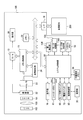
図1は、本発明の実施形態における撮像装置としてのデジタルカメラ100の構成例を示すブロック図である。図1において、103はフォーカスレンズを含む撮影レンズであり、101は絞り機能を備えるシャッターであり、22は光学像を電気信号に変換するCCDやCMOS素子等で構成される撮像部である。A/D変換器23は、撮像部22から出力されるアナログ信号をデジタル信号に変換する。バリア102は、撮影レンズ103、シャッター101、及び撮像部22を含む撮像系の汚れや破損を防止する。
First Embodiment
A first embodiment of the present invention will be described.
FIG. 1 is a block diagram showing a configuration example of a
画像処理部24は、A/D変換器23からのデータ及びメモリ制御部15からのデータに対し、所定の画素補間や縮小といったリサイズ処理や色変換処理を行う。また、画像処理部24では、撮像した画像データを用いて所定の演算処理が行われ、得られた演算結果に基づいてシステム制御部50が露光制御や測距制御を行う。これにより、TTL(スルー・ザ・レンズ)方式のAF(オートフォーカス)処理、AE(自動露出)処理、EF(フラッシュプリ発光)処理等が行われる。更に、画像処理部24によって得られた演算結果に基づいてTTL方式のAWB(オートホワイトバランス)処理も行っている。
The
A/D変換器23からの出力データは、画像処理部24及びメモリ制御部15、又はメモリ制御部15を介してメモリ32に書き込まれる。メモリ32は、撮像部22によって得られA/D変換器23でデジタルデータに変換された画像データや、表示部28に表示するための表示用の画像データを格納する。D/A変換器13は、メモリ32に格納されている表示用のデータをアナログ信号に変換する。表示部28は、LCD等の表示器上にD/A変換器13からのアナログ信号に応じた表示を行う。こうして、メモリ32に書き込まれた表示用の画像データは表示部28により表示される。
Output data from the A /
不揮発性メモリ56は、電気的に消去・記録可能なメモリである。不揮発性メモリ56は、例えばEEPROMである。不揮発性メモリ56には、システム制御部50の動作用の定数、プログラム等が記憶される。ここでいう、プログラムとは、例えば後述する各種フローチャートに示す本実施形態における処理を実行するためのプログラムである。
The
システム制御部50は、デジタルカメラ100全体を制御する。システム制御部50は、例えば不揮発性メモリ56に記録されたプログラムを実行することで、本実施形態における各処理を実現する。また、システム制御部50は、メモリ32、D/A変換器13、及び表示部28等を制御することにより表示制御も行う。システムメモリ52は、例えばRAMである。システムメモリ52には、システム制御部50の動作用の定数、変数、不揮発性メモリ56から読み出したプログラム等が展開される。
The
シャッターボタン61は、撮影指示を行うための操作部である。シャッターボタン61の操作途中、いわゆる半押し(撮影準備指示)でシャッタースイッチ信号SW1が出力される。シャッタースイッチ信号SW1の出力により、AF処理、AE処理、AWB処理、EF処理等の動作を開始する。また、シャッターボタン61の操作完了、いわゆる全押し(撮影指示)でシャッタースイッチ信号SW2が出力される。システム制御部50は、シャッタースイッチ信号SW2の出力により、撮像部22からの信号読み出しから記録媒体200への画像データ書き込みまでの一連の撮影処理の動作を開始する。
The
モード切替スイッチ60は、システム制御部50の動作モードを静止画記録モード、動画記録モード、再生モード等のいずれかに切り替える。操作部70は、システム制御部50に各種の動作指示を入力する。操作部70の各操作部材は、表示部28に表示される種々の機能アイコンを選択操作することなどにより、場面ごとに適宜機能が割り当てられ、各種機能ボタンとして作用する。また、表示部28上にタッチパネルを設け、表示パネル上を触れることで画面に表示された仮想的な操作部材を通して操作部70に対する操作を行えるようにしても良い。
The
電源制御部80は、電池の装着の有無、電池の種類、電池残量等の検出を行う。また、電源制御部80は、その検出結果及びシステム制御部50の指示に基づいて、必要な電圧を必要な期間、記録媒体200を含む各部へ供給する。電源部30は、デジタルカメラ100に対して電力を供給する。インターフェース部18は、半導体メモリや磁気ディスク等から構成される記録媒体200とのインターフェースである。電源スイッチ72は、電源オン、電源オフを切り替える。
The
顔検出部104は、メモリ32からのデータに対し被写体の顔情報の検出を行う。デジタルカメラ100では、撮影画面内の中央位置1点に対してAF制御を行う中央1点AFや顔検出機能によって検出された撮影画面内の顔に対してAF制御を行う顔AFを用いた撮影が可能である。
The
ここで、顔検出部104による顔検出機能について説明する。以下の顔検出に係る処理は、システム制御部50の制御下で顔検出部104が実行する。顔検出部104は、画像データに水平方向バンドパスフィルタを作用させ、更に処理された画像データに垂直方向バンドパスフィルタを作用させる。これら水平方向及び垂直方向のバンドパスフィルタにより、画像データからエッジ成分が検出される。その後、顔検出部104は、検出されたエッジ成分に関してパターンマッチングを行い、目及び鼻、口、耳の候補群を抽出する。
Here, the face detection function by the
そして、顔検出部104は、抽出された目の候補群の中から、予め設定された条件(例えば2つの目の距離、傾き等)を満たすものを目の対と判断し、目の対があるもののみ目の候補群として絞り込む。顔検出部104は、絞り込まれた目の候補群とそれに対応する顔を形成する他のパーツ(鼻、口、耳)を対応付け、また、予め設定した非顔条件フィルタを通すことで顔を検出する。顔検出部104は、顔の検出結果に応じて顔情報を出力して処理を終了する。このとき、顔情報をシステムメモリ52に記憶する。検出された顔情報とは、例えば、顔の大きさ、位置、傾き、また目、口などの器官部の位置情報である。
Then, the
サーチ処理部105は、撮像された画像に係る探索評価処理を行う。サーチ処理部105は、メモリ32に記憶されている被写体の画像データと現在のフレームの画像データに対しある領域毎に比較領域を変えながら各領域での相関処理を行う。サーチ処理部105は、例えば下記のような式(1)に従って、メモリ32に記憶されている探索対象である被写体の画像データと現在のフレームの画像データとの相関値を算出する。
The

ここで、Yi、Ui、Viは、現在のフレームにおけるある領域内(i=0〜M)の画素値を示しており、Yti、Uti、Vtiは、比較対象のターゲット画像の画素値を示している。ターゲット画像は、追尾したい被写体の画像データであり、事前にメモリ32に記憶されている。被写体の画像データは、表示部28に表示された画像と操作部70を用いてユーザによって指定された領域を切り出した画像データでもよいし、顔検出部104によって検出された顔情報から求められた顔領域を切り出した画像データでもよい。この式(1)は、相関が高いほど小さな値となる。
Here, Yi, Ui, and Vi indicate pixel values in an area (i = 0 to M) in the current frame, and Yti, Uti, and Vti indicate pixel values of the target image to be compared. There is. The target image is image data of an object to be tracked, and is stored in the
ここでは、式(1)により相関値を求めるようにしているが、記憶されている被写体の画像データと現在のフレームの画像データとの相関を求める方法は、これに限らない。例えば、ある領域のヒストグラムに基づく相関を求めてもよいし、形状の特徴点の類似状況から相関を求めてもよい。 Here, although the correlation value is determined by Equation (1), the method of determining the correlation between the stored image data of the subject and the image data of the current frame is not limited to this. For example, the correlation may be determined based on the histogram of a certain area, or the correlation may be determined from the similarity of feature points of the shape.
また、サーチ処理部105は、相関処理を行う1つの画像データ内において対象領域の位置をあるサーチステップ毎に移動しながら、すなわちサーチステップの間隔で比較する領域をずらしていくようにして処理を行う。これについては、後述詳しく説明する。
In addition, the
サーチ枠決定部106は、サーチ処理部105が探索評価処理(相関処理)を行う画像データの対象領域を指定する処理枠(以下、サーチ枠と称す)を決定する。サーチ処理部105で相関処理を行うにあたってサーチ枠決定部106は、サーチ枠の水平方向のサイズ(水平サイズ)WH及び垂直方向のサイズ(垂直サイズ)WVを決定する。また、サーチ枠決定部106は、相関処理を行う対象領域をどれだけの水平サーチステップHS及び垂直サーチステップVSの間隔で水平方向及び垂直方向にそれぞれ移動しながら処理していくかを決定する。
The search frame determination unit 106 determines a processing frame (hereinafter referred to as a search frame) for specifying a target area of image data for which the
次に、デジタルカメラ100において表示される被写体の表示枠について、図2を用いて説明する。図2は、表示部28に表示したライブ画像と被写体とともに表示した表示枠の例を示す図である。図2(a)には、被写体が人物である場合の表示画像の例を示しており、人物の顔の位置に表示枠201が表示されている。初期状態では、顔検出部104で検出された顔情報である顔位置や顔サイズ等から図2(a)に示すように表示枠201を表示することができる。
Next, the display frame of the subject displayed in the
図2(b)には、被写体が人物でない場合の表示画像の例を示しており、ここでは車という被写体に表示枠202が配置され表示されている。被写体が人物でない場合、例えばユーザが表示部28に表示された画像を見ながら被写体を操作部70のひとつであるタッチパネルを操作することによって被写体位置を指定することができる。このように初期状態において、ユーザによって指定された被写体位置に従って表示部28にて表示枠202を表示することを可能にしても良い。
FIG. 2B shows an example of a display image when the subject is not a person. Here, the
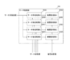
図3は、本実施形態におけるサーチ処理部105の構成例を示すブロック図である。図3に示すサーチ処理部301は、サーチ枠処理部302A、302B、302C、302D及び相関処理部303A、303B、303C、303Dを有する。サーチ枠処理部302A〜302Dは、サーチ枠情報に基づいて、入力されたサーチ対象画像からサーチ枠領域内の画像データに切り出す。すなわち、サーチ枠処理部302A〜302Dは、入力されたサーチ対象画像から、サーチ枠情報によって指定されるサーチ枠領域に対応する部分の画像データを選択して部分画像として切り出す。
FIG. 3 is a block diagram showing a configuration example of the
相関処理部303A〜303Dは、各サーチ枠処理部302A〜302Dで切り出された部分画像の画像データと被写体画像データとの相関値を求める相関値処理を行う。なお、サーチ枠処理部302A〜302Dにはそれぞれ入力画像に対して別のサーチ枠位置及びサイズを指定することができ、サーチ枠決定部106よりそれぞれ個別のサーチ枠位置及びサイズ情報をサーチ枠情報により指定する。
The
このように、本実施形態におけるサーチ処理部105は、並列に配置された複数の相関処理部303A〜303Dとそれに対応するサーチ枠処理部302A〜302Dとを有する。これにより、本実施形態におけるサーチ処理部105は、入力されたサーチ対象画像からのサーチ枠領域に対応する部分画像の切り出し並びに切り出した部分画像と被写体画像との相関処理を含む探索評価処理を並列に行うことが可能となっている。なお、図3には、サーチ枠処理部と相関処理部との組を4つ設けた例を示しているが、サーチ枠処理部及び相関処理部の個数はこれに限定されるものではなく、任意である。
As described above, the
次に、図4及び図5を用いて、サーチ処理部105によるサーチ処理について説明する。図4(a)〜図4(h)は、本実施形態における垂直方向のサーチ処理を説明するための図であり、左端の垂直サーチ領域における垂直方向のサーチ処理の例を示している。
Next, search processing by the
401はサーチ対象の画像全体であり、サーチ処理によって被写体画像との相関値を求める対象画像である。402は1つの垂直サーチ領域における垂直方向のサーチ処理の領域を示している。図4(a)〜図4(h)に示す垂直サーチ処理領域402は、画像401の左端の場合の例である。垂直サーチ処理領域402の幅は、水平方向でのサーチ位置によらず、サーチ枠の幅(サーチ枠の水平サイズ)WHである。
403は垂直方向のサーチ処理における画像401の処理領域402内での画像データの読み出し走査順を示している。本実施形態におけるサーチ処理では、領域402内を左上から左下の順に読み出し走査するものとする。404〜411はサーチ枠を示しており、水平サイズWH及び垂直サイズWVである。サーチ枠404〜411を垂直サーチステップVS(412〜418)毎に垂直方向に移動することによって、垂直方向に処理対象領域を移動させながら相関処理が行われていく。
図4(a)では、サーチ対象の画像における一番左上の領域とターゲット画像(被写体画像)との比較を行うため、図示のようにサーチ枠A1(404)を配置し、サーチ枠処理部A(302A)で画像切り出しを行い、相関処理部A(303A)で相関処理する。図4(b)では、サーチ枠A1(404)より垂直サーチステップVS(412)だけ下に移動した位置にサーチ枠B1(405)を配置し、サーチ枠処理部B(302B)で画像切り出しを行い、相関処理部B(303C)で相関処理する。 In FIG. 4A, a search frame A1 (404) is arranged as shown in FIG. 4 in order to compare the top left region of the image to be searched with the target image (subject image). The image is cut out in (302A), and correlation processing is performed in the correlation processing unit A (303A). In FIG. 4B, the search frame B1 (405) is disposed at a position moved downward by the vertical search step VS (412) from the search frame A1 (404), and the image cutting is performed by the search frame processing unit B (302B). The correlation processing unit B (303C) performs correlation processing.
図4(c)では、サーチ枠B1(405)より垂直サーチステップVS(413)だけ下に移動した位置にサーチ枠C1(406)を配置し、サーチ枠処理部C(302C)で画像切り出しを行い、相関処理部C(303C)で相関処理する。図4(d)では、サーチ枠C1(406)より垂直サーチステップVS(414)だけ下に移動した位置にサーチ枠D1(407)を配置し、サーチ枠処理部D(302D)で画像切り出しを行い、相関処理部D(303D)で相関処理する。 In FIG. 4C, the search frame C1 (406) is disposed at a position moved downward by the vertical search step VS (413) from the search frame B1 (405), and the image cutting is performed by the search frame processing unit C (302C). The correlation processing unit C (303C) performs correlation processing. In FIG. 4D, the search frame D1 (407) is arranged at the position moved downward by the vertical search step VS (414) from the search frame C1 (406), and the image cutting is performed by the search frame processing unit D (302D). The correlation processing unit D (303D) performs correlation processing.
図4(e)では、サーチ枠D1(407)より垂直サーチステップVS(415)だけ下に移動した位置にサーチ枠A2(408)を配置し、サーチ枠処理部A(302A)で画像切り出しを行い、相関処理部A(303A)で相関処理する。図4(f)では、サーチ枠A2(408)より垂直サーチステップVS(416)だけ下に移動した位置にサーチ枠B2(409)を配置し、サーチ枠処理部B(302B)で画像切り出しを行い、相関処理部B(303B)で相関処理する。 In FIG. 4E, the search frame A2 (408) is arranged at a position moved downward by the vertical search step VS (415) from the search frame D1 (407), and the image cutting is performed by the search frame processing unit A (302A). The correlation processing unit A (303A) performs correlation processing. In FIG. 4F, the search frame B2 (409) is disposed at a position moved downward by the vertical search step VS (416) from the search frame A2 (408), and the image cutting is performed by the search frame processing unit B (302B). The correlation processing unit B (303B) performs correlation processing.
図4(g)では、サーチ枠B2(409)より垂直サーチステップVS(417)だけ下に移動した位置にサーチ枠C2(410)を配置し、サーチ枠処理部C(302C)で画像切り出しを行い、相関処理部C(303C)で相関処理する。図4(h)では、サーチ枠C2(410)より垂直サーチステップVS(418)だけ下に移動した位置にサーチ枠D2(411)を配置し、サーチ枠処理部D(302D)で画像切り出しを行い、相関処理部D(303D)で相関処理する。以上のように垂直方向に繰り返し処理しながら垂直サーチ領域402の下端まで相関処理を繰り返し行う。
In FIG. 4 (g), the search frame C2 (410) is arranged at the position moved downward by the vertical search step VS (417) from the search frame B2 (409), and the image cutting is performed by the search frame processing unit C (302C). The correlation processing unit C (303C) performs correlation processing. In FIG. 4 (h), the search frame D2 (411) is disposed at a position moved downward by the vertical search step VS (418) from the search frame C2 (410), and the image cutting is performed by the search frame processing unit D (302D). The correlation processing unit D (303D) performs correlation processing. As described above, the correlation processing is repeatedly performed to the lower end of the
ここで、図3に示したような4並列処理ができるサーチ処理部105で、4つの並列回路を使いまわしながら繰り返して処理を効率良く行うためには、図4(e)に示すようにサーチ枠の配置位置の間519に条件式(VS×N)≧WVが成り立つ必要がある。すなわち、ある回路に対応するサーチ枠の配置位置の間隔、例えばサーチ枠A1(404)とサーチ枠A2(408)との配置位置の間隔は条件式(VS×N)≧WVが成り立つ必要がある。ここで、VSは垂直サーチステップであり、Nはサーチ処理の並列回路数であり、WVはサーチ枠の垂直サイズである。本実施形態におけるサーチ処理部105の例では、並列回路数は4でN=4である。
Here, in order to perform processing repeatedly and efficiently while using four parallel circuits in the
前述した条件式(VS×N)≧WVは、サーチ枠B1(405)とサーチ枠B2(409)との間、サーチ枠C1(406)とサーチ枠C2(410)との間、サーチ枠D1(407)とサーチ枠D2(411)との間でも成り立つ必要がある。また、繰り返し処理を行う中で再配置されるサーチ枠との間でも同様の条件が成り立つ必要がある。なお、本例では、サーチ処理部105での並列動作できる処理回路の個数が4つの場合を示しているが、他のN個の並列回路である場合も同様の条件を満たすことが必要である。
The conditional expression (VS × N) ≧ WV described above is between the search frame B1 (405) and the search frame B2 (409), between the search frame C1 (406) and the search frame C2 (410), the search frame D1 It is necessary to hold between (407) and the search frame D2 (411). In addition, the same condition needs to be satisfied between the search frame to be rearranged during the repetitive processing. In this example, although the case where the number of processing circuits capable of parallel operation in the
図5(a)〜図5(f)は、本実施形態における水平方向のサーチ処理を説明するための図である。図5(a)に示す画像データの読み出し走査601で、図4(a)〜図4(h)で説明した垂直方向のサーチ処理が一通り行われることを示している。これと同様の垂直サーチ処理を水平方向にサーチ領域を水平サーチステップHS(507〜511)毎に移動しながらサーチ処理を行うことを示している。 FIG. 5A to FIG. 5F are diagrams for explaining search processing in the horizontal direction in the present embodiment. In the image data read scan 601 shown in FIG. 5A, it is shown that the search process in the vertical direction described with reference to FIGS. 4A to 4H is performed. The same vertical search processing is shown to be performed while moving the search region in the horizontal direction in each horizontal search step HS (507 to 511).
図5(b)に示す画像データの読み出し走査502では、図5(a)に示した画像データの読み出し走査501から水平サーチステップHS(507)だけ右の領域を読み出し走査して垂直サーチ処理することを示している。図5(c)に示す画像データの読み出し走査503では、図5(b)に示した画像データの読み出し走査502から水平サーチステップHS(508)だけ右の領域を読み出し走査して垂直サーチ処理することを示している。
In the image
図5(d)に示す画像データの読み出し走査504では、図5(c)に示した画像データの読み出し走査503から水平サーチステップHS(509)だけ右の領域を読み出し走査して垂直サーチ処理することを示している。図5(e)に示す画像データの読み出し走査505では、図5(d)に示した画像データの読み出し走査504から水平サーチステップHS(510)だけ右の領域を読み出し走査して垂直サーチ処理することを示している。
In the image data read scan 504 shown in FIG. 5D, the area on the right is read and scanned by the horizontal search step HS (509) from the image data read scan 503 shown in FIG. It is shown that. In the image
以上のように水平方向に垂直サーチ処理を行う領域を移動しながら繰り返し垂直サーチ処理を行い、図5(f)に示す画像データの読み出し走査506のようにサーチ処理対象画像401の右端の領域を読み出し走査して垂直サーチ処理するところまで処理を行う。
As described above, the vertical search processing is repeatedly performed while moving the region to be subjected to the vertical search processing in the horizontal direction, and the region at the right end of the search
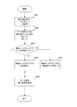
図6は、本実施形態におけるサーチ枠決定部106及びサーチ処理部105での処理例を示すフローチャートである。ステップS601にて、サーチ枠決定部106は、被写体の位置と、被写体の水平サイズH及び垂直サイズVとを取得する。被写体が人物であり、かつ顔検出部104で顔が検出された場合には、これらの情報を検出されている顔情報から取得すれば良い。被写体が人物でない場合には、これらの情報を、例えば表示部28及び操作部70のひとつであるタッチパネルによるユーザ指定により被写体情報から得るようにしても良い。
FIG. 6 is a flowchart showing a process example of the search frame determination unit 106 and the
ステップS602にて、サーチ枠決定部106は、サーチ枠の水平サイズWH及び垂直サイズWVを、それぞれステップS601において取得した被写体の水平サイズH及び垂直サイズVに決定する。ステップS603にて、サーチ枠決定部106は、ステップS602において決定したサーチ枠の垂直サイズWV(=V)が、式VS≧(WV/N)を満たすか否かを判別する。ここで、VSは垂直サーチステップであり、WVはサーチ枠の垂直サイズであり、Nはサーチ処理部105で使用する並列回路数である。言い換えれば、垂直サーチステップとサーチ処理部105で使用する並列回路数との積がサーチ枠の垂直サイズ以上であるか否かを判別する。第1の実施形態では、初期の垂直サーチステップVSは、水平サーチステップHSとともに現在のフレームの被写体の位置を求める際の処理時間や被写体位置の精度などから予め決められている。
In step S602, the search frame determination unit 106 determines the horizontal size WH and the vertical size WV of the search frame as the horizontal size H and the vertical size V of the subject acquired in step S601, respectively. In step S603, the search frame determination unit 106 determines whether the vertical size WV (= V) of the search frame determined in step S602 satisfies the equation VS ((WV / N). Here, VS is the vertical search step, WV is the vertical size of the search frame, and N is the number of parallel circuits used in the
ステップS602において決定したサーチ枠の垂直サイズWV(=V)が、式VS≧(WV/N)を満たす場合には(ステップS603のYes)、ステップS604へ進む。ステップS604にて、サーチ枠決定部106は、予め決められている垂直サーチステップVSを変更せずに、次のステップS606へ進む。 If the vertical size WV (= V) of the search frame determined in step S602 satisfies the equation VS ((WV / N) (Yes in step S603), the process proceeds to step S604. In step S604, the search frame determination unit 106 proceeds to the next step S606 without changing the predetermined vertical search step VS.
ステップS602において決定したサーチ枠の垂直サイズWV(=V)が、式VS≧(WV/N)を満たさない場合には(ステップS603のYes)、ステップS605へ進む。ステップS605にて、サーチ枠決定部106は、ステップS602において決定したサーチ枠の垂直サイズWVとサーチ処理部105で使用する並列回路数Nとに基づいて、垂直サーチステップVSを変更する。サーチ枠決定部106は、サーチ枠の垂直サイズWVとサーチ処理部105の並列回路数Nとから式VS=(WV/N)で求められた値に垂直サーチステップVSを変更し、次のステップS606へ進む。
If the vertical size WV (= V) of the search frame determined in step S602 does not satisfy the equation VS ((WV / N) (Yes in step S603), the process proceeds to step S605. In step S605, the search frame determination unit 106 changes the vertical search step VS based on the vertical size WV of the search frame determined in step S602 and the number N of parallel circuits used in the
ステップS606にて、サーチ処理部105は、サーチ枠決定部106で決定したサーチ枠の水平サイズWH及び垂直サイズWVと、水平サーチステップHS及び垂直サーチステップVSに従ってサーチ処理を行い、被写体位置を取得する。サーチ処理については、指定されたサーチ枠に従ってサーチ対象の画像から部分画像を切り出し、切り出した部分画像と被写体画像との相関処理を、図4及び図5を用いて説明したとおりに比較する領域を変えながら行う。
In step S606, the
第1の実施形態によれば、垂直サーチステップとサーチ処理部の並列回路数との積がサーチ枠の垂直サイズ以上でない場合には、垂直サーチステップを、サーチ枠の垂直サイズをサーチ処理部の並列回路数で分けた値に変更する。これにより、垂直サーチステップとサーチ処理部の並列回路数との積がサーチ枠の垂直サイズ以上となる。したがって、サーチ対象の画像データの2度読みやサーチ対象の画像データを一時記憶する余分なメモリなどを必要とせず、回路規模やコストの増大を抑えつつ、処理効率の良い被写体追尾機能等の探索評価処理を実現可能な撮像装置を提供することができる。 According to the first embodiment, when the product of the vertical search step and the number of parallel circuits in the search processing unit is not equal to or larger than the vertical size of the search frame, the vertical search step Change the value divided by the number of parallel circuits. As a result, the product of the vertical search step and the number of parallel circuits in the search processing unit becomes equal to or larger than the vertical size of the search frame. Therefore, it is not necessary to read twice the image data to be searched or an extra memory for temporarily storing the image data to be searched, etc., while suppressing increase in circuit size and cost, and searching for an object tracking function with high processing efficiency. It is possible to provide an imaging device capable of realizing the evaluation process.
(第2の実施形態)
次に、本発明の第2の実施形態について説明する。なお、第2の実施形態における撮像装置の一例であるデジタルカメラの構成は、第1の実施形態において図1、図2、図3を用いて説明したデジタルカメラの構成と同様である。また、サーチ処理部105の動作は、図4及び図5を用いて説明したサーチ処理の動作と同様である。
Second Embodiment
Next, a second embodiment of the present invention will be described. The configuration of a digital camera, which is an example of the imaging apparatus according to the second embodiment, is the same as the configuration of the digital camera described with reference to FIGS. 1, 2 and 3 in the first embodiment. Further, the operation of the
図7は、第2の実施形態におけるサーチ枠決定部106及びサーチ処理部105での処理例を示すフローチャートである。ステップS701にて、サーチ枠決定部106は、第1の実施形態におけるステップS601と同様に、被写体の位置と、被写体の水平サイズH及び垂直サイズVとを取得する。
FIG. 7 is a flowchart showing a process example of the search frame determination unit 106 and the
ステップS702にて、サーチ枠決定部106は、ステップS701において取得された被写体の垂直サイズVが、式V≦(VS×N)を満たすか否かを判別する。ここで、Vは被写体の垂直サイズであり、VSは垂直サーチステップであり、Nはサーチ処理部105で使用する並列回路数である。つまり、第1の実施形態と同様に、垂直サーチステップとサーチ処理部の並列回路数との積がサーチ枠の垂直サイズ以上であるか否かを判別する。第2の実施形態では、垂直サーチステップVSは、水平サーチステップHSとともに現在のフレームの被写体の位置を求める際の処理時間や被写体位置の精度などから予め決められている。
In step S702, the search frame determination unit 106 determines whether the vertical size V of the subject acquired in step S701 satisfies the formula V ≦ (VS × N). Here, V is the vertical size of the subject, VS is the vertical search step, and N is the number of parallel circuits used in the
被写体の垂直サイズVが式V≦(VS×N)を満たす場合には(ステップS702のYes)、ステップS703へ進む。ステップS703にて、サーチ枠決定部106は、サーチ枠の水平サイズWH及び垂直サイズWVを、それぞれステップS701において取得した被写体の水平サイズH及び垂直サイズVに決定し、ステップS705へ進む。 If the vertical size V of the subject satisfies the equation V ≦ (VS × N) (Yes in step S702), the process advances to step S703. In step S703, the search frame determination unit 106 determines the horizontal size WH and the vertical size WV of the search frame as the horizontal size H and the vertical size V of the subject acquired in step S701, respectively, and the process proceeds to step S705.
他方、被写体の垂直サイズVが式V≦(VS×N)を満たさない場合には(ステップS702のNo)、ステップS704へ進む。ステップS704にて、サーチ枠決定部106は、垂直サーチステップVSとサーチ処理部105で使用する並列回路数Nとから式WV=(VS×N)で求められる値をサーチ枠の垂直サイズWVとして、ステップS705へ進む。なお、ステップS704においても、サーチ枠決定部106は、サーチ枠の水平サイズWHを、ステップS701において取得した被写体の水平サイズHに決定する。
On the other hand, when the vertical size V of the subject does not satisfy the equation V ≦ (VS × N) (No in step S702), the process proceeds to step S704. In step S704, search frame determination unit 106 sets a value obtained by the formula WV = (VS × N) from vertical search step VS and the number N of parallel circuits used by
ステップS705にて、サーチ処理部105は、サーチ枠決定部106で決定したサーチ枠の水平サイズWH及び垂直サイズWVと、水平サーチステップHS及び垂直サーチステップVSに従ってサーチ処理を行い、被写体位置を取得する。サーチ処理については、指定されたサーチ枠に従ってサーチ対象の画像から部分画像を切り出し、切り出した部分画像と被写体画像との相関処理を、図4及び図5を用いて説明したように比較する領域を変えながら行う。
In step S705, the
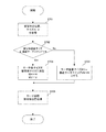
次に、第2の実施形態での表示枠の表示処理について説明する。図8は、第2の実施形態における表示枠の表示処理の例を示すフローチャートである。被写体の位置を示す表示枠の初期サイズや位置は、図2(a)及び図2(b)を用いて説明したように顔検出の結果やユーザ指定によって決まる。その後、ライブビュー表示や動画表示といった連続したフレーム画像を表示している中で被写体に追従して表示枠もサーチ処理結果に従って表示位置を移動する。 Next, display processing of the display frame in the second embodiment will be described. FIG. 8 is a flowchart showing an example of display processing of a display frame in the second embodiment. The initial size and position of the display frame indicating the position of the subject are determined by the result of face detection and user specification as described with reference to FIGS. 2 (a) and 2 (b). After that, while displaying continuous frame images such as live view display and moving image display, the display frame also moves the display position according to the search processing result following the subject.
ステップS801にて、サーチ枠決定部106においてサーチ枠のサイズを被写体サイズと同じとしたか否かを判別する。同じである場合には(ステップS801のYes)、ステップS802へ進む。ステップS802では、サーチ処理結果より得られた最も被写体と相関のあるサーチ枠の位置及びサイズを表示画像とともに表示する表示枠の位置及びサイズとして、表示部28にて表示させる。なお、相関が高いほど上述した式(1)で得られる値は小さくなるため、相関値をそのまま評価値とするならば、評価値が最も小さいサーチ枠の位置およびサイズを、表示枠の位置及びサイズとして選択する。これに対し、相関値の逆数を評価値とするならば、評価値が最も大きいサーチ枠の位置およびサイズを、表示枠の位置及びサイズとして選択する。
In step S801, the search frame determination unit 106 determines whether the size of the search frame is equal to the subject size. If they are the same (Yes at step S801), the process proceeds to step S802. In step S802, the
一方、同じでない場合には(ステップS801のNo)、ステップS803へ進む。ステップS803では、表示画像とともに表示する表示枠のサイズは前回表示した表示枠のサイズとする。また、ステップS804にて、サーチ処理結果より得られた最も被写体と相関のあるサーチ枠の位置及びサイズからサーチ枠の重心位置を求め、求めた重心位置に表示枠の重心位置を移動して表示部28にて表示させる。
On the other hand, if they are not the same (No at step S801), the process proceeds to step S803. In step S 803, the size of the display frame displayed together with the display image is the size of the display frame displayed last time. Also, in step S804, the barycentric position of the search frame is obtained from the position and size of the search frame that is most correlated with the subject obtained from the search processing result, and the barycentric position of the display frame is moved to the obtained barycentric position for display It is displayed in
なお、ここではサーチ処理結果に基づいて表示枠の位置を決定する例について説明したが、新たに顔検出結果、及びユーザ指定などがあった場合には、これに従い表示枠の位置やサイズを決定するようにしても良い。 Although the example of determining the position of the display frame based on the search processing result has been described here, if there is a new face detection result and user designation, the position and size of the display frame are determined accordingly. You may do it.
第2の実施形態によれば、垂直サーチステップとサーチ処理部の並列回路数との積がサーチ枠の垂直サイズ以上でない場合には、サーチ枠の垂直サイズを、垂直サーチステップとサーチ処理部の並列回路数との積に変更する。これにより、垂直サーチステップとサーチ処理部の並列回路数との積がサーチ枠の垂直サイズ以上となる。したがって、サーチ対象の画像データの2度読みやサーチ対象の画像データを一時記憶する余分なメモリなどを必要とせず、回路規模やコストの増大を抑えつつ、処理効率の良い被写体追尾機能等の探索評価処理を実現可能な撮像装置を提供することができる。 According to the second embodiment, when the product of the vertical search step and the number of parallel circuits in the search processing unit is not more than the vertical size of the search frame, the vertical size of the search frame Change to the product of the number of parallel circuits. As a result, the product of the vertical search step and the number of parallel circuits in the search processing unit becomes equal to or larger than the vertical size of the search frame. Therefore, it is not necessary to read twice the image data to be searched or an extra memory for temporarily storing the image data to be searched, etc., while suppressing increase in circuit size and cost, and searching for an object tracking function with high processing efficiency. It is possible to provide an imaging device capable of realizing the evaluation process.
(第3の実施形態)
次に、本発明の第3の実施形態について説明する。なお、第3の実施形態における撮像装置の一例であるデジタルカメラの構成は、第1の実施形態において図1、図2、図3を用いて説明したデジタルカメラの構成と同様である。また、サーチ処理部105の動作は、図4及び図5を用いて説明したサーチ処理の動作と同様である。
Third Embodiment
Next, a third embodiment of the present invention will be described. The configuration of a digital camera, which is an example of the imaging apparatus according to the third embodiment, is the same as the configuration of the digital camera described with reference to FIGS. 1, 2 and 3 in the first embodiment. Further, the operation of the
図9は、第3の実施形態におけるサーチ枠決定部106及びサーチ処理部105での処理例を示すフローチャートである。ステップS901にて、サーチ枠決定部106は、第1の実施形態におけるステップS601と同様に、被写体の位置と、被写体の水平サイズH及び垂直サイズVとを取得する。
FIG. 9 is a flowchart showing a process example of the search frame determination unit 106 and the
ステップS902にて、サーチ枠決定部106は、ステップS901において取得された被写体の垂直サイズVが、式V≦(VS×N)を満たすか否かを判別する。ここで、Vは被写体の垂直サイズであり、VSは垂直サーチステップであり、Nはサーチ処理部105で使用する並列回路数である。第3の実施形態では、垂直サーチステップVSは、水平サーチステップHSとともに現在のフレームの被写体の位置を求める際の処理時間や被写体位置の精度などから予め決められている。
In step S902, the search frame determination unit 106 determines whether the vertical size V of the subject acquired in step S901 satisfies the formula V ≦ (VS × N). Here, V is the vertical size of the subject, VS is the vertical search step, and N is the number of parallel circuits used in the
被写体の垂直サイズVが式V≦(VS×N)を満たす場合には(ステップS902のYes)、ステップS903へ進む。ステップS903にて、サーチ枠決定部106は、サーチ枠の水平サイズWH及び垂直サイズWVを、それぞれステップS901において取得した被写体の水平サイズH及び垂直サイズVに決定し、ステップS906へ進む。 If the vertical size V of the subject satisfies the equation V ≦ (VS × N) (Yes in step S902), the process advances to step S903. In step S903, the search frame determination unit 106 determines the horizontal size WH and the vertical size WV of the search frame as the horizontal size H and the vertical size V of the subject acquired in step S901, respectively, and the process proceeds to step S906.
被写体の垂直サイズVが式V≦(VS×N)を満たさない場合には(ステップS902のNo)、ステップS904へ進む。ステップS904にて、サーチ枠決定部106は、垂直サーチステップVSとサーチ処理部105で使用する並列回路数Nとから式WV=(VS×N)で求められる値をサーチ枠の垂直サイズWVとして、ステップS905へ進む。続く、ステップS905にて、サーチ枠決定部106は、被写体の水平サイズH及び垂直サイズVとサーチ枠の垂直サイズWVとから式WH=(H×V/WV)で求められる値をサーチ枠の水平サイズWHとして、ステップS906へ進む。なお、ここでは一例として前記の式にて求める方法を説明したがこれに限らない。
If the vertical size V of the subject does not satisfy the equation V ≦ (VS × N) (No in step S902), the process advances to step S904. In step S904, search frame determination unit 106 sets a value obtained by the formula WV = (VS × N) from vertical search step VS and the number N of parallel circuits used by
ステップS906にて、サーチ処理部105は、サーチ枠決定部106で決定したサーチ枠の水平サイズWH及び垂直サイズWVと、水平サーチステップHS及び垂直サーチステップVSに従ってサーチ処理を行い、被写体位置を取得する。サーチ処理については、指定されたサーチ枠に従ってサーチ対象の画像から部分画像を切り出し、切り出した部分画像と被写体画像との相関処理を、図4及び図5を用いて説明したように比較する領域を変えながら行う。
In step S906, the
ここで、被写体の位置を示す表示枠については、第2の実施形態と同様に、ライブビュー表示や動画表示といった連続したフレーム画像を表示している中で被写体に追従してサーチ処理結果に従って表示位置を移動する。この表示枠のサイズや位置についての処理も第2の実施形態と同様であり、前述した図8に示したフローチャートと同様の処理を行えば良い。 Here, the display frame indicating the position of the subject is displayed according to the search processing result following the subject while displaying the continuous frame images such as live view display and moving image display as in the second embodiment. Move the position. The processing for the size and position of the display frame is the same as that of the second embodiment, and the same processing as the flowchart shown in FIG. 8 described above may be performed.
第3の実施形態によれば、第2の実施形態と同様に、回路規模やコストの増大を抑えつつ、処理効率の良い被写体追尾機能等の探索評価処理を実現可能な撮像装置を提供することができる。なお、第1乃至第3の実施形態では、探索評価処理の結果を用いて被写体の表示枠を表示する例をあげて説明を行ったが、これに限られるものではない。探索評価処理の結果を、オートフォーカス、測光、あるいは、ホワイトバランス処理における処理対象の領域の選択や、領域に対する重み付け係数の演算に利用してもよい。あるいは、画像データを記録する際に、被写体が存在する領域を示す情報としてメタデータに含めるようにしてもよい。 According to the third embodiment, as in the second embodiment, it is possible to provide an imaging device capable of realizing a search evaluation process such as a subject tracking function with high processing efficiency while suppressing increases in circuit size and cost. Can. In the first to third embodiments, although the example in which the display frame of the subject is displayed using the result of the search evaluation process is described, the present invention is not limited to this. The result of the search evaluation process may be used for selecting an area to be processed in auto focus, photometry, or white balance process, or for calculating a weighting factor for the area. Alternatively, when image data is recorded, the metadata may include information indicating an area where a subject is present.
(本発明の他の実施形態)
また、本発明は、以下の処理を実行することによっても実現される。即ち、前述した実施形態の機能を実現するソフトウェア(プログラム)を、ネットワーク又は各種記憶媒体を介してシステム或いは装置に供給し、そのシステム或いは装置のコンピュータ(またはCPUやMPU等)がプログラムを読み出して実行する処理である。
(Other embodiments of the present invention)
The present invention is also realized by executing the following processing. That is, software (program) for realizing the functions of the above-described embodiments is supplied to a system or apparatus via a network or various storage media, and a computer (or CPU or MPU or the like) of the system or apparatus reads the program. It is a process to execute.
なお、前記実施形態は、何れも本発明を実施するにあたっての具体化のほんの一例を示したものに過ぎず、これらによって本発明の技術的範囲が限定的に解釈されてはならないものである。すなわち、本発明はその技術思想、又はその主要な特徴から逸脱することなく、様々な形で実施することができる。 In addition, the said embodiment shows only an example of implementation in all in implementing this invention, and the technical scope of this invention should not be limitedly interpreted by these. That is, the present invention can be implemented in various forms without departing from the technical concept or the main features thereof.
100:撮像装置 22:撮像部 28:表示部 32:メモリ 50:システム制御部 52:システムメモリ 70:操作部 104:顔検出部 105:サーチ処理部 106:サーチ枠決定部 301:サーチ処理部 302A〜302D:サーチ枠処理部 303A〜303D:相関処理部
100: imaging device 22: imaging unit 28: display unit 32: memory 50: system control unit 52: system memory 70: operation unit 104: face detection unit 105: search processing unit 106: search frame determination unit 301:
Claims (9)
撮像部によって得られ入力される画像から、前記複数の第1の処理手段に入力する部分画像を指定された処理枠に従ってそれぞれ切り出す第2の処理手段と、
垂直方向における前記処理枠の間隔と前記第1の処理手段の個数との積が前記処理枠の垂直方向のサイズ以上となるように、前記処理枠の垂直方向のサイズ及び垂直方向における前記処理枠の間隔の少なくとも一方を決定する決定手段と、
前記撮像部によって得られた画像に対する前記複数の第1の処理手段による探索評価処理で得られた評価値に基づいて、探索対象である被写体が存在する位置を決定する制御手段とを有することを特徴とする撮像装置。 A plurality of first processing means capable of performing a search and evaluation process related to an image in parallel;
From an image input obtained by the imaging unit, a second processing means to cut out respectively in accordance with the processing frame to the specified partial image to be input to the plurality of first processing means,
As the product of the number of intervals between the first processing means of the processing frame in the vertical direction is equal to or greater than the size in the vertical direction of the processing frame, the processing in the size and the vertical direction in the vertical direction of the process frame Determining means for determining at least one of the intervals of the frame;
Controlling means for determining the position where the subject to be searched for is present based on the evaluation value obtained by the search evaluation process by the plurality of first processing means for the image obtained by the imaging unit. An imaging device characterized by
前記顔検出手段により検出された顔を前記被写体画像とすることを特徴とする請求項2記載の撮像装置。 A face detection unit that detects the face of the subject from the input image;
3. The image pickup apparatus according to claim 2, wherein the face detected by the face detection unit is used as the subject image.
被写体のサイズ又は前回表示した表示枠のサイズに基づいて決定したサイズの前記表示枠を表示することを特徴とする請求項1〜6の何れか1項に記載の撮像装置。 A display unit configured to display a display frame based on the processing frame determined by the control unit together with the image obtained by the imaging unit;
The imaging apparatus according to any one of claims 1 to 6, wherein the display frame having a size determined based on the size of the subject or the size of the display frame displayed last time is displayed.
前記複数の第1の処理手段による探索評価処理の結果から求まる位置に基づいて前記表示枠を表示する位置を決定することを特徴とする請求項1〜7の何れか1項に記載の撮像装置。 A display unit configured to display a display frame based on the processing frame determined by the control unit together with the image obtained by the imaging unit;
The image pickup apparatus according to any one of claims 1 to 7, wherein the position to display the display frame is determined based on the position obtained from the result of the search evaluation process by the plurality of first processing means. .
前記複数の第1の処理手段に入力する部分画像を指定するための処理枠の垂直方向における間隔と前記第1の処理手段の個数との積が前記処理枠の垂直方向のサイズ以上となるように、前記処理枠の垂直方向のサイズ及び垂直方向における前記処理枠の間隔の少なくとも一方を決定する工程と、
撮像部によって得られ入力される画像から、前記複数の第1の処理手段に入力する部分画像を決定された処理枠に従ってそれぞれ切り出す工程と、
切り出された画像に係る探索評価処理を前記複数の第1の処理手段にて行う工程と、
前記撮像部によって得られた画像に対する前記複数の第1の処理手段による探索評価処理で得られた評価値に基づいて、探索対象である被写体が存在する位置を決定する工程とを有することを特徴とする画像処理方法。 It is an image processing method in an imaging apparatus having a plurality of first processing means capable of performing search evaluation processing relating to an image in parallel,
The product of the interval in the vertical direction of the processing frame for specifying the partial image to be input to the plurality of first processing means and the number of the first processing means is equal to or larger than the size in the vertical direction of the processing frame in the step of determining at least one of spacing of the processing frame in the size and the vertical direction in the vertical direction of the processing frame,
Cutting out partial images to be input to the plurality of first processing units from the images obtained and input by the imaging unit according to the determined processing frame;
Performing a search and evaluation process on the clipped image by the plurality of first processing means;
Determining the position where the subject to be searched for is present, based on the evaluation values obtained by the search evaluation processing by the plurality of first processing means on the image obtained by the imaging unit. Image processing method.
Priority Applications (2)
| Application Number | Priority Date | Filing Date | Title |
|---|---|---|---|
| JP2015105797A JP6512938B2 (en) | 2015-05-25 | 2015-05-25 | Imaging apparatus and image processing method |
| US15/161,099 US10089519B2 (en) | 2015-05-25 | 2016-05-20 | Image capturing apparatus and image processing method |
Applications Claiming Priority (1)
| Application Number | Priority Date | Filing Date | Title |
|---|---|---|---|
| JP2015105797A JP6512938B2 (en) | 2015-05-25 | 2015-05-25 | Imaging apparatus and image processing method |
Publications (3)
| Publication Number | Publication Date |
|---|---|
| JP2016220144A JP2016220144A (en) | 2016-12-22 |
| JP2016220144A5 JP2016220144A5 (en) | 2018-06-14 |
| JP6512938B2 true JP6512938B2 (en) | 2019-05-15 |
Family
ID=57398958
Family Applications (1)
| Application Number | Title | Priority Date | Filing Date |
|---|---|---|---|
| JP2015105797A Active JP6512938B2 (en) | 2015-05-25 | 2015-05-25 | Imaging apparatus and image processing method |
Country Status (2)
| Country | Link |
|---|---|
| US (1) | US10089519B2 (en) |
| JP (1) | JP6512938B2 (en) |
Families Citing this family (1)
| Publication number | Priority date | Publication date | Assignee | Title |
|---|---|---|---|---|
| DE102017208718A1 (en) * | 2017-05-23 | 2018-11-29 | Conti Temic Microelectronic Gmbh | Method of detecting objects in an image of a camera |
Family Cites Families (8)
| Publication number | Priority date | Publication date | Assignee | Title |
|---|---|---|---|---|
| JP3192872B2 (en) | 1994-05-30 | 2001-07-30 | 三洋電機株式会社 | Motion vector detection circuit and subject tracking camera device using the same |
| JP3539788B2 (en) * | 1995-04-21 | 2004-07-07 | パナソニック モバイルコミュニケーションズ株式会社 | Image matching method |
| JP3803150B2 (en) * | 1996-10-29 | 2006-08-02 | 株式会社日立製作所 | Image processing device |
| JP2009223527A (en) * | 2008-03-14 | 2009-10-01 | Seiko Epson Corp | Image processor, image processing method, and computer program for image processing |
| JP5067282B2 (en) * | 2008-06-27 | 2012-11-07 | ソニー株式会社 | Object detection control device, object detection system, object detection control method, and program |
| FR2939547B1 (en) * | 2008-12-09 | 2011-06-10 | Commissariat Energie Atomique | DEVICE AND METHOD FOR RECOGNIZING AND LOCATING OBJECTS IN A SCAN IMAGE OF SENSOR WINDOWS |
| JP5390363B2 (en) * | 2009-12-10 | 2014-01-15 | 国立大学法人広島大学 | Feature detection device, program for causing computer to execute feature detection, and computer-readable recording medium recording the program |
| JP2012142865A (en) | 2011-01-05 | 2012-07-26 | Sony Corp | Image processing apparatus and image processing method |
-
2015
- 2015-05-25 JP JP2015105797A patent/JP6512938B2/en active Active
-
2016
- 2016-05-20 US US15/161,099 patent/US10089519B2/en active Active
Also Published As
| Publication number | Publication date |
|---|---|
| JP2016220144A (en) | 2016-12-22 |
| US20160350924A1 (en) | 2016-12-01 |
| US10089519B2 (en) | 2018-10-02 |
Similar Documents
| Publication | Publication Date | Title |
|---|---|---|
| JP4735742B2 (en) | Imaging apparatus, strobe image generation method, and program | |
| US9607240B2 (en) | Image processing apparatus, image capturing apparatus, image processing method, image capturing method, and non-transitory computer-readable medium for focus bracketing | |
| US7725019B2 (en) | Apparatus and method for deciding in-focus position of imaging lens | |
| EP2547089A1 (en) | Electronic zoom device, electronic zoom method, and program | |
| US7614559B2 (en) | Apparatus and method for deciding in-focus position of imaging lens | |
| JP7223079B2 (en) | IMAGE PROCESSING APPARATUS, CONTROL METHOD THEREOF, AND IMAGING APPARATUS | |
| US9070008B2 (en) | Object recognition apparatus and dictionary data registration method | |
| US20190149719A1 (en) | Image capturing apparatus, image capturing method, and storage medium | |
| JP2014077994A (en) | Image display device, control method and control program for the same, and imaging device | |
| JP6525809B2 (en) | Focus detection apparatus and control method thereof | |
| JP7158841B2 (en) | Imaging device, imaging method, program, recording medium, and image processing device | |
| JP2014186580A (en) | Authentication device, imaging device, registration method of authentication data, program, and storage medium | |
| US11323689B2 (en) | Image processing device, imaging device, image processing method, and recording medium | |
| JP4771536B2 (en) | Imaging device and method of selecting face as main subject | |
| JP6512938B2 (en) | Imaging apparatus and image processing method | |
| JP4807623B2 (en) | Imaging apparatus, imaging method, and imaging program | |
| JP5509621B2 (en) | Image processing apparatus, camera, and program | |
| JP5278483B2 (en) | Imaging apparatus, imaging method, and imaging program | |
| JP2023165555A (en) | Image processing apparatus, imaging apparatus, control method, and program | |
| JP2019191661A (en) | Image processing apparatus, imaging device, image processing method, and program | |
| JP5743729B2 (en) | Image synthesizer | |
| JP6033044B2 (en) | Image display apparatus, control method thereof, control program, and imaging apparatus | |
| JP6157238B2 (en) | Image processing apparatus, image processing method, and image processing program | |
| JP2006039254A (en) | Camera | |
| JP7458723B2 (en) | Image processing device, imaging device, control method, and program |
Legal Events
| Date | Code | Title | Description |
|---|---|---|---|
| A521 | Request for written amendment filed |
Free format text: JAPANESE INTERMEDIATE CODE: A523 Effective date: 20180426 |
|
| A621 | Written request for application examination |
Free format text: JAPANESE INTERMEDIATE CODE: A621 Effective date: 20180426 |
|
| TRDD | Decision of grant or rejection written | ||
| A01 | Written decision to grant a patent or to grant a registration (utility model) |
Free format text: JAPANESE INTERMEDIATE CODE: A01 Effective date: 20190312 |
|
| A61 | First payment of annual fees (during grant procedure) |
Free format text: JAPANESE INTERMEDIATE CODE: A61 Effective date: 20190409 |
|
| R151 | Written notification of patent or utility model registration |
Ref document number: 6512938 Country of ref document: JP Free format text: JAPANESE INTERMEDIATE CODE: R151 |