JP2009044463A - Electronic camera and field image reproduction device - Google Patents
Electronic camera and field image reproduction device Download PDFInfo
- Publication number
- JP2009044463A JP2009044463A JP2007207281A JP2007207281A JP2009044463A JP 2009044463 A JP2009044463 A JP 2009044463A JP 2007207281 A JP2007207281 A JP 2007207281A JP 2007207281 A JP2007207281 A JP 2007207281A JP 2009044463 A JP2009044463 A JP 2009044463A
- Authority
- JP
- Japan
- Prior art keywords
- image
- face
- area
- scene image
- reproducing
- Prior art date
- Legal status (The legal status is an assumption and is not a legal conclusion. Google has not performed a legal analysis and makes no representation as to the accuracy of the status listed.)
- Pending
Links
Images


Classifications
-
- G—PHYSICS
- G06—COMPUTING; CALCULATING OR COUNTING
- G06V—IMAGE OR VIDEO RECOGNITION OR UNDERSTANDING
- G06V40/00—Recognition of biometric, human-related or animal-related patterns in image or video data
- G06V40/10—Human or animal bodies, e.g. vehicle occupants or pedestrians; Body parts, e.g. hands
- G06V40/16—Human faces, e.g. facial parts, sketches or expressions
- G06V40/161—Detection; Localisation; Normalisation
- G06V40/166—Detection; Localisation; Normalisation using acquisition arrangements
-
- G—PHYSICS
- G06—COMPUTING; CALCULATING OR COUNTING
- G06V—IMAGE OR VIDEO RECOGNITION OR UNDERSTANDING
- G06V10/00—Arrangements for image or video recognition or understanding
- G06V10/10—Image acquisition
- G06V10/12—Details of acquisition arrangements; Constructional details thereof
- G06V10/14—Optical characteristics of the device performing the acquisition or on the illumination arrangements
- G06V10/147—Details of sensors, e.g. sensor lenses
-
- H—ELECTRICITY
- H04—ELECTRIC COMMUNICATION TECHNIQUE
- H04N—PICTORIAL COMMUNICATION, e.g. TELEVISION
- H04N23/00—Cameras or camera modules comprising electronic image sensors; Control thereof
- H04N23/60—Control of cameras or camera modules
- H04N23/61—Control of cameras or camera modules based on recognised objects
- H04N23/611—Control of cameras or camera modules based on recognised objects where the recognised objects include parts of the human body
-
- H—ELECTRICITY
- H04—ELECTRIC COMMUNICATION TECHNIQUE
- H04N—PICTORIAL COMMUNICATION, e.g. TELEVISION
- H04N23/00—Cameras or camera modules comprising electronic image sensors; Control thereof
- H04N23/60—Control of cameras or camera modules
- H04N23/63—Control of cameras or camera modules by using electronic viewfinders
- H04N23/633—Control of cameras or camera modules by using electronic viewfinders for displaying additional information relating to control or operation of the camera
- H04N23/635—Region indicators; Field of view indicators
-
- H—ELECTRICITY
- H04—ELECTRIC COMMUNICATION TECHNIQUE
- H04N—PICTORIAL COMMUNICATION, e.g. TELEVISION
- H04N23/00—Cameras or camera modules comprising electronic image sensors; Control thereof
- H04N23/60—Control of cameras or camera modules
- H04N23/69—Control of means for changing angle of the field of view, e.g. optical zoom objectives or electronic zooming
-
- H—ELECTRICITY
- H04—ELECTRIC COMMUNICATION TECHNIQUE
- H04N—PICTORIAL COMMUNICATION, e.g. TELEVISION
- H04N23/00—Cameras or camera modules comprising electronic image sensors; Control thereof
- H04N23/70—Circuitry for compensating brightness variation in the scene
- H04N23/72—Combination of two or more compensation controls
-
- H—ELECTRICITY
- H04—ELECTRIC COMMUNICATION TECHNIQUE
- H04N—PICTORIAL COMMUNICATION, e.g. TELEVISION
- H04N23/00—Cameras or camera modules comprising electronic image sensors; Control thereof
- H04N23/60—Control of cameras or camera modules
- H04N23/67—Focus control based on electronic image sensor signals
- H04N23/673—Focus control based on electronic image sensor signals based on contrast or high frequency components of image signals, e.g. hill climbing method
Landscapes
- Engineering & Computer Science (AREA)
- Multimedia (AREA)
- Signal Processing (AREA)
- Theoretical Computer Science (AREA)
- General Health & Medical Sciences (AREA)
- Physics & Mathematics (AREA)
- General Physics & Mathematics (AREA)
- Health & Medical Sciences (AREA)
- Oral & Maxillofacial Surgery (AREA)
- Human Computer Interaction (AREA)
- Vascular Medicine (AREA)
- Studio Devices (AREA)
- Television Signal Processing For Recording (AREA)
Abstract
Description
この発明は、電子カメラ及び被写界像再生装置に関し、特にたとえば被写界像内の特定位置に注目して再生する、電子カメラ及び被写界像再生装置に関する。 The present invention relates to an electronic camera and an object scene image reproducing device, and more particularly to an electronic camera and an object image image reproducing device that reproduces paying attention to a specific position in an object image, for example.
電子カメラであるデジタルスチルカメラを用いて撮影して得られた画像データを再生する際、当該画像データによって表される被写体像に含まれる顔画像を検出し、検出された顔画像を拡大し表示する画像再生装置が特許文献1に開示されている。
しかし、特許文献1では、画像データによって表される被写体像に含まれる顔画像を、再生時に検出し拡大表示する部分を決めているため、拡大表示される部分が撮影時に指定した部分、すなわちピントをあわせようとした部分と一致しない可能性がある。また、特許文献1に開示された技術を応用し、撮影時にピントをあわせようとした部分を顔に限ることなく、例えば建物や背景でも可能にする場合、再生時に当該部分を再生装置が検出し拡大表示するようにするには、再生装置が具備する当該部分を検出する検出手段の構成が複雑になるという課題がある。
However, in
それゆえに、この発明の主たる目的は、簡単な構成で撮影時に指定した位置に応じて被写界像を再生することができる、電子カメラや被写界像再生装置を提供することである。 SUMMARY OF THE INVENTION Therefore, a main object of the present invention is to provide an electronic camera and a field image reproducing apparatus that can reproduce a field image according to a position designated at the time of shooting with a simple configuration.
第1の発明は、被写界を捉える撮像面を有し、被写界像を生成する撮像手段、撮像手段によって生成される被写界像内の特定位置を指定する指定手段、撮像手段によって生成された被写界像を、指定手段によって指定された特定位置の位置情報と共に記録する記録手段、および記録手段によって記録された被写界像を記録手段によって記録された位置情報を用いて再生を行う再生手段を具える、電子カメラである。 According to a first aspect of the present invention, there is provided an imaging unit that has an imaging surface for capturing an object scene, generates an object scene image, a designation unit that specifies a specific position in the object scene image generated by the imaging unit, and an imaging unit Recording means for recording the generated scene image together with position information at a specific position designated by the designation means, and reproducing the object scene image recorded by the recording means using the position information recorded by the recording means An electronic camera comprising a reproducing means for performing
さらに、撮像手段によって生成された被写界像に含まれる特徴画像を探索する探索手段を具え、指定手段は探索手段によって検知された特徴画像の位置に基づいて特定位置を指定することを特徴とする。 Further, the image processing apparatus includes a search unit that searches for a feature image included in the object scene image generated by the imaging unit, and the specifying unit specifies a specific position based on the position of the feature image detected by the search unit. To do.
さらに、指定手段によって指定された特定位置の被写界像に基づいて前記撮像手段の撮影条件を調整する調整手段を具え、記録手段は調整手段によって調整された撮像条件で作成された被写界像を記録することを特徴とし、撮影条件は撮像手段の焦点距離であることを特徴とする。 Further, the image processing apparatus further includes an adjusting unit that adjusts a shooting condition of the imaging unit based on an object scene image at a specific position specified by the specifying unit, and the recording unit is a scene created under the imaging condition adjusted by the adjusting unit. It is characterized in that an image is recorded, and the photographing condition is a focal length of the imaging means.
さらに、再生手段は、記録手段によって記録された位置情報を用いて特定される位置を中心に被写界像を拡大再生することを特徴とする。 Further, the reproducing means is characterized in that the object scene image is enlarged and reproduced around the position specified by using the position information recorded by the recording means.
第2の発明は、被写界像内の特定位置を示す位置情報と当該被写界像と共に記録された記録媒体から被写界像を再生する被写界像再生装置であって、被写界像を前記位置情報を用いて再生を行う再生手段を具える、被写界像再生装置である。 A second invention is a scene image reproducing apparatus for reproducing a scene image from a position information indicating a specific position in the scene image and a recording medium recorded together with the scene image. An object scene image reproducing apparatus comprising a reproducing means for reproducing a field image using the position information.
さらに、再生手段は、当該位置情報を用いて特定される位置を中心に被写界像を拡大再生することを特徴とする。 Further, the reproducing means is characterized in that the object scene image is enlarged and reproduced around the position specified by using the position information.
第1及び第2の発明によれば、撮影時に指定した被写界像内の特定位置が再生時の再生機能に簡単且つ確実に反映される電子カメラや被写界像再生装置を提供することができる。 According to the first and second inventions, it is possible to provide an electronic camera and an object scene image reproducing device in which a specific position in an object scene image designated at the time of shooting is reflected easily and reliably on the reproducing function at the time of reproduction. Can do.
本願発明の目的、特徴および利点は、図面を参照して行う以下の実施例の詳細な説明から一層明らかとなろう。 The objects, features and advantages of the present invention will become more apparent from the following detailed description of embodiments with reference to the drawings.
図1を参照して、本発明の第1実施例であるディジタルカメラ10は、光学レンズ12を含む。被写界の光学像は、光学レンズ12を通してイメージセンサ14の撮像面14fに照射され、光電変換を施される。これによって、被写界を表す電荷つまり生画像信号が生成される。
Referring to FIG. 1, a
電源が投入されると、CPU42は、スルー画像処理を実行するべく、プリ露光および間引き読み出しの繰り返しをTG/SG18に命令する。TG/SG18は、イメージセンサ14の撮像面14fのプリ露光と、これによって得られた電荷の間引き読み出しとを実行するべく、複数のタイミング信号をイメージセンサ14に与える。撮像面14fで生成された生画像信号は、1/30秒に1回の割合で発生する垂直同期信号Vsyncに応答して、ラスタ走査に従う順序で読み出される。
When the power is turned on, the
イメージセンサ14から出力された生画像信号は、CDS/AGC/AD回路16によって相関二重サンプリング、自動ゲイン調整およびA/D変換の一連の処理を施される。信号処理回路20は、CDS/AGC/AD回路16から出力された生画像データに白バランス調整,色分離,YUV変換などの処理を施し、YUV形式の画像データをメモリ制御回路26を通してSDRAM28の表示画像領域28aに書き込む。
The raw image signal output from the
ビデオエンコーダ30は、表示画像領域28aに格納された画像データをメモリ制御回路26を通して1/30秒毎に読み出し、読み出された画像データをコンポジットビデオ信号に変換する。この結果、被写界を表すリアルタイム動画像(スルー画像)がLCDモニタ32に表示される。
The
AE/AF評価回路24は、信号処理回路20から出力された画像データに基づいて、被写界の明るさを示す輝度評価値と被写界の合焦度を示すフォーカス評価値とを作成する。作成された輝度評価値およびフォーカス評価値は、CPU42に与えられる。
Based on the image data output from the
キー入力装置46に設けられたシャッタボタン46Sが操作されていないとき、CPU42は、スルー画像用AE処理とAF処理を実行する。TG/SG18に設定されたプリ露光時間は、AE/AF評価回路24からの輝度評価値に基づいて制御される。これによって、スルー画像の明るさが適度に調整される。AE/AF評価回路24からのフォーカス評価値に基づいたAF処理、所謂画像信号の高周波成分が最大となるように光学レンズ12を設定する山登りオートフォーカス処理に基づき、光学レンズ12はドライバ44によって駆動される。
When the
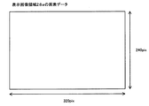
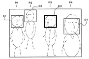
図2を参照して、表示画像領域28aは、縦240画素、横320画素の画像データからなり、顔検出を行う探索領域として設定される。そして、図3(A)に示す最大サイズの顔判別領域が探索領域の左上に配置される。顔判別領域の左上座標は、探索領域の左上座標と一致する。
Referring to FIG. 2, the
顔判別領域に属する部分画像の特徴量は、フラッシュメモリ48に記憶された辞書の特徴量と照合される。照合処理の結果、注目する部分画像が顔画像と判別されると、現時点の顔判別領域のサイズ、顔判別領域の中心位置および信頼度が記述された顔情報が作成され、SDRAM28の顔情報領域28dに格納される。信頼度とは、顔判別領域に属する部分画像の特徴量と、フラッシュメモリ48に記憶された辞書の特徴量との照合処理において両者が一致する割合を示すのもであり、一致する割合が高いと、顔と判別した信頼度が大きくなる。顔判別領域は、ラスタ方向に既定量(=1画素)ずつ移動される。顔判別領域は、図4に示す要領で探索領域を移動する。
The feature amount of the partial image belonging to the face discrimination area is collated with the feature amount of the dictionary stored in the
なお、当該信頼度は、フラッシュメモリ48に記憶された辞書によって左右されるが、一般的に、正面を向いた顔の方が、斜めや下を向いた顔よりも高い信頼度で顔を検出することができる。
The reliability depends on the dictionary stored in the
顔判別領域が探索領域の右下に到達すると、つまり顔判別領域の右下座標が探索領域の右下座標と一致すると、図3(A)に示す顔判別領域に代えて図3(B)に示すミドルサイズの顔判別領域が探索領域の左上に配置され、上述と同様の処理が再度実行される。ミドルサイズの顔判別領域が探索領域の右下に到達すると、図3(C)に示す最小サイズの顔判別領域が探索領域の左上に配置され、上述と同様の処理が繰り返される。 When the face discrimination area reaches the lower right corner of the search area, that is, when the lower right coordinates of the face discrimination area coincide with the lower right coordinates of the search area, the face discrimination area shown in FIG. The middle size face discrimination area shown in FIG. 5 is arranged at the upper left of the search area, and the same processing as described above is executed again. When the middle size face discrimination area reaches the lower right of the search area, the minimum size face discrimination area shown in FIG. 3C is arranged at the upper left of the search area, and the same processing as described above is repeated.
このように、特徴量の照合処理および顔判別領域の移動処理は、サイズの大きい順に最大サイズ、ミドルサイズ、最小サイズの3つの顔判別領域を順次用いることによって3回実行される。処理の途中で顔画像が発見されると、その時点の顔判別領域の中心の位置、サイズおよび信頼度が記述された顔情報が作成され、顔情報領域28dに格納された顔情報が更新される。
In this manner, the feature amount matching process and the face discrimination area moving process are executed three times by sequentially using the three face discrimination areas of the maximum size, middle size, and minimum size in order of size. When a face image is found during the process, face information describing the position, size and reliability of the center of the face discrimination area at that time is created, and the face information stored in the
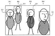
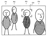
顔情報が得られると、CPU42は、この顔情報によって定義されるキャラクタC1のOSD表示をキャラクタジェネレータ34に命令する。キャラクタジェネレータ34は、顔情報に記述されたサイズを有するキャラクタC1を顔情報に記述された位置に表示するべく、キャラクタデータをLCDモニタ32に与える。キャラクタC1は、図5に示すように4人の人物P1、P2、P3、P4が入った被写界像であれば、顔検出の結果、図6に示す要領でスルー画像に多重表示される。
When the face information is obtained, the
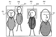
そして、得られた顔情報が1つであれば当該顔が検出された顔の位置に、複数の顔が検出されている場合は、画角中心位置から最も近い顔の位置に、フォーカス評価値を得る領域を設定し、当該設定が行われたことを表示するべく、キャラクタデータをLCDモニタ32に与える。キャラクタC2は、図5に示すように4人の人物P1、P2、P3、P4が入った被写界像であれば、画角中心位置から最も近い顔の位置は人物P3の顔の位置となり、図7に示す要領でスルー画像に多重表示される。
Then, if the obtained face information is one, the focus evaluation value is set at the position of the face where the face is detected, and when a plurality of faces are detected, the focus evaluation value is set at the position of the face closest to the view angle center position. The character data is given to the
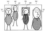
シャッタボタン46Sが半押しされると、CPU42は、顔情報の検出結果によって異なる態様でAF処理およびAE処理を実行する。顔情報が検出されなかったとき、CPU42は、撮像面の中央領域を基準としてAE処理およびAF処理を実行する。撮像面の中央領域とは、撮影しようとする被写体が含まれている可能性が高い領域として撮像面の中央に設けられたものであり、詳細な説明は割愛する。これに対して、顔情報が検出されたとき、CPU42は、この顔情報を用いて撮像面上に指定される指定領域を決定し、指定領域を表示するべく、キャラクタデータをLCDモニタ32に与える。キャラクタC3は、図5に示すように4人の人物P1、P2、P3、P4が写った被写界像であれば、たとえば図8に示す要領で、後述するAF処理によって光学レンズ12の合焦位置設定が完了した時点でスルー画像に多重表示される。キャラクタC3が表示されることによって、使用者はAF処理が完了したことを知ることができる。指定領域は、検出された顔情報が1つであれば顔判別処理において当該顔が検出された時の顔判別領域の位置に、複数の顔が検出されている場合は、顔判別処理において画角中心位置から最も近い顔が検出された時の顔判別領域の位置に設定する。そして、指定領域を重視してAE処理を実行し、指定領域を基準として、すなわち、指定領域から得られる画像信号を用いてAF処理を実行する。AE処理の結果、TG/SG18に設定された露光時間は最適値に設定される。また、AF処理の結果、光学レンズ12はドライバ44によって合焦位置に設定される。
When the
図5に示すように4人の人物P1、P2、P3、P4が入った被写界像であれば、図6に示すように4つの顔判別領域で顔情報が検出される。画角中心位置から最も近い顔が検出された顔判別領域の位置は人物P3の顔を検出した判別領域であるため、図9に示すように、人物P1の顔を検出した判別領域に相当する領域を領域E1、人物P2の顔を検出した判別領域に相当する領域を領域E2、人物P3の顔を検出した判別領域に相当する領域を領域E3、人物P4の顔を検出した判別領域に相当する領域を領域E4とすると、指定領域は、人物P3の顔を検出した判別領域に相当する領域E3となる。AE処理は、指定領域となった領域E3から得られる輝度評価値を重視し、他の領域である領域E1、E2、E4から得られる輝度評価値と共に用いて行う。本実施例では、領域E3から得られる輝度評価値の寄与度を50%、領域E1、E2、E3から得られる輝度評価値全体の寄与度を50%として算出した輝度評価値を用いてAE処理を行う。 If the object scene image includes four persons P1, P2, P3, and P4 as shown in FIG. 5, the face information is detected in the four face discrimination areas as shown in FIG. Since the position of the face discrimination area where the face closest to the view angle center position is detected is the discrimination area where the face of the person P3 is detected, it corresponds to the discrimination area where the face of the person P1 is detected as shown in FIG. The region is the region E1, the region corresponding to the discrimination region where the face of the person P2 is detected is the region E2, the region corresponding to the discrimination region where the face of the person P3 is detected is the region E3, and the discrimination region where the face of the person P4 is detected If the area to be performed is an area E4, the designated area is an area E3 corresponding to the discrimination area in which the face of the person P3 is detected. In the AE process, the luminance evaluation value obtained from the area E3 that is the designated area is regarded as important, and is used together with the luminance evaluation values obtained from the areas E1, E2, and E4 which are other areas. In this embodiment, the AE process is performed using the luminance evaluation values calculated with the contribution of the luminance evaluation value obtained from the region E3 as 50% and the contribution of the entire luminance evaluation value obtained from the regions E1, E2, and E3 as 50%. I do.
シャッタボタン46Sが全押しされると、CPU42は、記録処理を実行するべく、本露光および全画素読み出しをTG/SG18に命令し、JPEG圧縮をJPEGエンコーダ36に命令する。
When the
なお、領域E1、E2、E3、E4の位置と大きさは、人物P1、P2、P3、P4の顔を検出した判別領域の位置と大きさに基づいて設定するが、両者は厳密に同じである必要はない。領域E1、E2、E3、E4の位置と大きさは、例えば撮像面14fに設定された縦16個、横16個、全256個の部分領域を組み合わせて設定される。
Note that the positions and sizes of the areas E1, E2, E3, and E4 are set based on the positions and sizes of the discrimination areas in which the faces of the persons P1, P2, P3, and P4 are detected. There is no need. The positions and sizes of the regions E1, E2, E3, and E4 are set by combining, for example, 16 vertical regions, 16 horizontal regions, and a total of 256 partial regions set on the
TG/SG18は、イメージセンサ14の撮像面14fの本露光と、これによって得られた全ての電荷の読み出しとを実行するべく、複数のタイミング信号をイメージセンサ14に与える。撮像面14fで生成された生画像信号は、ラスタ走査に従う順序で読み出される。イメージセンサ14から出力された生画像信号は、CDS/AGC/AD回路16によって相関二重サンプリング、自動ゲイン調整およびA/D変換の一連の処理を施される。信号処理回路20は、CDS/AGC/AD回路16から出力された生画像データに白バランス調整,色分離,YUV変換などの処理を施し、表示画像領域28aに格納される画像データよりも解像度の高いYUV形式の画像データ、ずなわち、イメージセンサ14の全画素で構成される画像データ、全画素の数は約500万個であり、縦1944画素、横2592画素の画像データに変換される。変換された画像データは、メモリ制御回路26を通してSDRAM28の非圧縮画像領域28bに書き込まれる。
The TG /
JPEGエンコーダ36は、非圧縮画像領域28bに格納された画像データをメモリ制御回路26を通して読み出し、読み出された画像データをJPEG方式で圧縮し、そして圧縮画像データつまりJPEGデータをメモリ制御回路26を通して圧縮画像領域28cに書き込む。こうして得られたJPEGデータはその後、CPU42によって読み出され、顔情報が検出されたことによって決定された指定領域の位置を示す位置情報があれば、当該位置情報と共にI/F38を経てファイル形式で記録媒体40に記録される。記録媒体40には複数の画像ファイルが記録可能である。
The
次に再生動作について説明する。I/F38を介してファイル形式で記録媒体40に記録されているファイルの1つを選択してJPEGデータを読み出し、SDRAM28の圧縮画像領域28cに書き込む。JPEGデコーダ37は、圧縮画像領域28cに格納されたJPEGデータをメモリ制御回路26を通して読み出し、読み出されたJPEGデータを伸張し、得られた画像データをメモリ制御回路26を通して非圧縮画像領域28bに書き込む。非圧縮画像領域28bに書き込まれた画像データをメモリ制御回路26を通して読み出し、読み出された画像データから、当該画像データよりも解像度が低い表示用の画像データを作成し、SDRAM28の表示画像領域28aに書き込む。
Next, the reproduction operation will be described. One of the files recorded on the
ビデオエンコーダ30は、表示画像領域28aに格納された画像データをメモリ制御回路26を通して1/30秒毎に読み出し、読み出された画像データをコンポジットビデオ信号に変換する。この結果、再生画像がLCDモニタ32に表示される。
The
記録媒体40にJPEGデータと共に上述の位置情報が記録されており読み出し可能であれば、当該位置情報を基に再生ズーム処理の中心位置に設定し、ズーム表示を行う。当該位置情報が得られないJPEGデータであれば画像の中心を再生ズーム処理の中心位置に設定し、ズーム表示を行う。
If the above-mentioned position information is recorded together with JPEG data on the
ズーム表示は、非圧縮画像領域28bに書き込まれた画像データを、ズーム倍率とズーム中心位置に基づいてズーム処理することによって得られた画像データを表示画像領域28aに格納することによって行う。
Zoom display is performed by storing, in the
なお、記録媒体40に記録されている当該位置情報は、表示画像領域28aに格納された画像データ上の画素数で表わした位置情報であるため、再生の際は、SDRAM28の非圧縮画像領域28bに書き込まれた画像データ上の画素数で表わす位置情報に換算して再生ズーム処理に用いられる。表示画像領域28aは、縦240画素、横320画素の画像データからなっている。JPEGデータを再生することによってSDRAM28の非圧縮画像領域28bに書き込まれた画像データが、縦1944画素、横2592画素であれば、1944を240で除算した値である「8.1」を表示画像領域28aに書き込まれた画像データの縦位置を表わす値に乗算し、2592を320で除算した値である「8.1」を表示画像領域28aに書き込まれた画像データの横位置を表わす値に乗算しすることによって、記録媒体40に記録されている当該位置情報を、JPEGデータを再生することによってSDRAM28の非圧縮画像領域28bに書き込まれた画像データ上での位置を示す位置情報に換算して再生ズーム処理に用いる。
Since the position information recorded on the
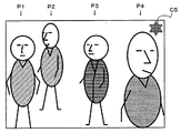
なお、当該位置情報を再生ズーム処理の中心位置に設定した場合、当該中心位置を表示するべく、キャラクタデータをLCDモニタ32に与える。キャラクタC4は、たとえば図10に示す要領で再生画像に多重表示される。キャラクタC4は設定された中心位置を示すものであるが、JPEGデータに対応した位置情報を基に再生ズーム処理の中心位置が設定されたことを示すキャラクタデータをLCDモニタ32に与え、キャラクタC5を図11に示す要領で再生画像に多重表示してもよく、さらに、このようなキャラクタC4やキャラクタC5の表示はしなくてもよい。
When the position information is set as the center position of the reproduction zoom process, character data is given to the
仮に、記録媒体40から読み出したJPEGデータに付随した位置情報によって再生ズーム処理の中心が設定されなければ、図12の(A)から(B)(C)に示すように、画像の中心がズーム処理の中心位置となり拡大表示されるので、拡大表示操作の後に中心位置を変更する必要が生じるが、同じ再生画像であっても、当該位置情報によって再生ズーム処理の中心が設定されると、図13の(A)から(B)(C)に示すように、当該位置情報に対応した位置が中心位置となり拡大表示されるので、より簡単に撮影時にディジタルカメラ10が注目した位置に応じて拡大再生することができる。
If the center of the reproduction zoom process is not set by the position information attached to the JPEG data read from the
CPU42は、撮影動作時、図14、図15に示す撮影メインタスクと図16、図17に示す顔検出タスクとを含む複数のタスクを並列的に実行する。なお、これらのタスクに対応する制御プログラムは、フラッシュメモリ48に記憶されている。
During the shooting operation, the
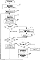
まず図14を参照して、ステップS1では顔検出タスクを起動し、ステップS3ではスルー画像処理を実行する。ステップS1の処理によって図16、図17に示す顔検出タスクの処理が開始される。ステップS3の処理によって、スルー画像がLCDモニタ32に表示される。
First, referring to FIG. 14, a face detection task is activated in step S1, and through image processing is executed in step S3. The processing of the face detection task shown in FIGS. 16 and 17 is started by the processing of step S1. The through image is displayed on the
ステップS5では、キー入力装置46からキー状態信号を取り込む。ステップS7ではシャッタボタン46Sが半押しされたか否かを判別し、NOであれば、ステップS9でスルー画像用AE/AF処理を実行してからステップS5に戻る。
In step S5, a key state signal is taken from the
ステップS9で示したスルー画像用AE/AF処理は図15に示すフローチャートに従って行われる。ステップS911で後で述べる顔探索処理によって顔が検出されたことを示す顔検出フラグの値が1であるか否かを判別し、YESであれば、ステップS913で顔情報を用いて指定領域の決定を行う。指定領域は、検出された顔情報が1つであれば顔判別処理において当該顔が検出された時の顔判別領域の中心位置に、複数の顔が検出されている場合は、画角中心位置から最も近い顔が検出された時の顔判別領域の中心位置に設定する。 The through image AE / AF process shown in step S9 is performed according to the flowchart shown in FIG. In step S911, it is determined whether or not the value of the face detection flag indicating that a face has been detected by the face search process described later is 1, and if YES, the face information is used to identify the designated area in step S913. Make a decision. The designated area is the center position of the angle of view when a plurality of faces are detected at the center position of the face discrimination area when the face is detected in the face discrimination process if the detected face information is one. Is set to the center position of the face discrimination area when the closest face is detected.
そして、ステップS915で指定領域を示すキャラクタ表示(キャラクタC2の表示)を行い、ステップS917で指定領域を重視するAE処理を行い、ステップS919で指定領域を基準とするAF処理を行い、上階層のルーチンに復帰する。 In step S915, a character display indicating the designated area (display of the character C2) is performed. In step S917, AE processing that places importance on the designated area is performed. In step S919, AF processing based on the designated area is performed. Return to routine.
AE処理は、指定領域から得られる輝度評価値を重視し、他の顔判別領域に相当する領域から得られる輝度評価値を共に用いて行う。 In the AE process, the luminance evaluation value obtained from the designated area is emphasized, and the luminance evaluation value obtained from an area corresponding to another face discrimination area is used together.
一方、ステップS911でNOであれば、ステップS923で被写界像の中央領域を重視するAE処理を行い、ステップS925で被写界像の中央領域を基準とするAF処理を行い、上階層のルーチンに復帰する。 On the other hand, if “NO” in the step S911, an AE process that emphasizes the center area of the object scene image is performed in a step S923, and an AF process that uses the center area of the object scene image as a reference is performed in a step S925, Return to routine.
なお、ステップS9で示したスルー画像用AE/AF処理としては、顔探索処理によって顔が検出されたか否かに係らず、簡易なAE/AF処理として、被写界像の中央領域を重視するAE処理と、被写界像の中央領域を基準とするAF処理を行うようにしてもよい。 Note that the through-image AE / AF process shown in step S9 places importance on the center area of the object scene image as a simple AE / AF process regardless of whether or not a face is detected by the face search process. AE processing and AF processing based on the center area of the object scene image may be performed.
図14に戻って説明を続ける。ステップS7でYESであれば、ステップS11で顔探索処理によって顔が検出されたことを示す顔検出フラグの値が1であるか否かを判別し、YESであれば、ステップS13で顔情報を用いて指定領域の決定を行う。指定領域は、検出された顔情報が1つであれば顔判別処理において当該顔が検出された時の顔判別領域の位置に、複数の顔が検出されている場合は、顔判別処理において画角中心位置から最も近い顔が検出された時の顔判別領域の位置に設定する。 Returning to FIG. 14, the description will be continued. If “YES” in the step S7, it is determined whether or not the value of a face detection flag indicating that a face is detected by the face search process in a step S11 is 1. If “YES”, the face information is determined in a step S13. Use to determine the designated area. The designated area has one face information detected in the face discrimination process if a plurality of faces are detected at the position of the face discrimination area when the face is detected in the face discrimination process if the detected face information is one. It is set to the position of the face discrimination area when the face closest to the corner center position is detected.
そして、ステップS15で指定領域を示すキャラクタ表示(キャラクタC3の表示)を行い、ステップS17で指定領域を重視するAE処理を行い、ステップS19で指定領域を基準とするAF処理を行い、ステップS21に進む。 In step S15, the character display indicating the designated area (display of the character C3) is performed, in step S17, AE processing that places importance on the designated area is performed, in step S19, AF processing is performed with reference to the designated area, and in step S21. move on.
AE処理は、指定領域となった顔判別領域から得られる輝度評価値を重視し、他の顔判別領域から得られる輝度評価値と共に用いて行う。例えば、図5に示すように4人の人物P1、P2、P3、P4が入った被写界像であれば、図6に示すように4つの顔判別領域で顔情報が検出される。画角中心位置から最も近い顔が検出された顔判別領域の位置は人物P3の顔を検出した判別領域であるため、図9に示すように、人物P1の顔を検出した判別領域に相当する領域を領域E1、人物P2の顔を検出した判別領域に相当する領域を領域E2、人物P3の顔を検出した判別領域に相当する領域を領域E3、人物P4の顔を検出した判別領域に相当する領域を領域E4とすると、指定領域は、人物P3の顔を検出した判別領域に相当する領域E3となる。そして、領域E3から得られる輝度評価値の寄与度を50%、領域E1、E2、E3から得られる輝度評価値全体の寄与度を50%として算出した輝度評価値を用いてAE処理を行う。 In the AE process, the luminance evaluation value obtained from the face discrimination area that is the designated area is regarded as important, and is used together with the luminance evaluation value obtained from other face discrimination areas. For example, in the case of an object scene image including four persons P1, P2, P3, and P4 as shown in FIG. 5, face information is detected in four face discrimination areas as shown in FIG. Since the position of the face discrimination area where the face closest to the view angle center position is detected is the discrimination area where the face of the person P3 is detected, it corresponds to the discrimination area where the face of the person P1 is detected as shown in FIG. The region is the region E1, the region corresponding to the discrimination region where the face of the person P2 is detected is the region E2, the region corresponding to the discrimination region where the face of the person P3 is detected is the region E3, and the discrimination region where the face of the person P4 is detected If the area to be performed is an area E4, the designated area is an area E3 corresponding to the discrimination area in which the face of the person P3 is detected. Then, the AE process is performed using the luminance evaluation value calculated with the contribution of the luminance evaluation value obtained from the region E3 as 50% and the contribution of the entire luminance evaluation value obtained from the regions E1, E2, and E3 as 50%.
一方、ステップS11でNOであれば、ステップS23で被写界像の中央領域を重視するAE処理を行い、ステップS25で被写界像の中央領域を基準とするAF処理を行い、ステップS21に進む。 On the other hand, if “NO” in the step S11, an AE process in which the center area of the object scene image is emphasized is performed in a step S23, and an AF process using the center area of the object scene image as a reference is performed in a step S25. move on.
ステップS21では、ステップS5と同様にキー入力装置46からキー状態信号を取り込む。
In step S21, a key state signal is taken from the
ステップS27ではシャッタボタン46Sが半押しされた状態か否かを判別し、YESであれば、ステップS21に戻る。よって、シャッタボタン46Sの半押しが継続された状態では、ステップS15によるキャラクタ表示やステップS17、S19、又はステップS23、S25による撮影条件の調整値が固定される。
In step S27, it is determined whether or not the
ステップS27でNOであれば、ステップS29でシャッタボタン46Sが全押しされたか否かを判別し、YESであれば、ステップS31で記録処理を実行し、終了する。ステップS29でNOであれば、シャッタボタン46sが全押しされることなく半押し状態が解除されたと判断し、ステップS15で表示した指定領域を示すキャラクタを消去するステップS33を実行しステップS9に進む。
If “NO” in the step S27, it is determined whether or not the
ステップS31の処理によって、シャッタボタン46sが操作された時点の被写界像を表すJPEGデータがファイル形式で記録媒体40に記録される。詳細は後で説明する。
By the processing in step S31, JPEG data representing the object scene image at the time when the shutter button 46s is operated is recorded on the
次に顔検出タスクについて説明する。図16を参照して、ステップS41では顔情報を初期化し、顔情報が全く得られていない状態に設定する。垂直同期信号Vsyncが発生するとステップS43でYESと判断し、ステップS45で顔探索処理を実行し、ステップS47では顔探索処理によって顔が検出されたことを示す顔検出フラグの値が1であるか否かを判別する。YESすなわち値が1で顔検出フラグの値が顔探索処理によって顔が検出された値を示していれば、顔情報に応じてキャラクタC1を表示し、NOであれば当該キャラクタC1を非表示とし、ステップS43に戻る。キャラクタC1は、図5に示すような4人の人物P1、P2、P3、P4が写った被写界像であれば、図6に示す要領でスルー画像に多重表示される。 Next, the face detection task will be described. Referring to FIG. 16, in step S41, face information is initialized and set to a state in which no face information is obtained. When the vertical synchronization signal Vsync is generated, YES is determined in step S43, face search processing is executed in step S45, and whether the value of the face detection flag indicating that a face has been detected by face search processing is 1 in step S47. Determine whether or not. If YES, that is, if the value is 1 and the value of the face detection flag indicates that the face is detected by the face search process, the character C1 is displayed according to the face information, and if NO, the character C1 is not displayed. Return to step S43. If the character C1 is an object scene image in which four persons P1, P2, P3, and P4 as shown in FIG. 5 are captured, the character C1 is displayed in multiple on the through image as shown in FIG.
ステップS45として示した顔探索処理は、図17に示すサブルーチンに従って実行される。まずステップS61で顔判別領域の設定を初期化する。これによって、最大サイズの顔判別領域が表示画像領域28aに設定された探索領域の左上に配置される。顔判別領域は、顔判別領域の左上座標が探索領域の左上座標と一致するように、図2に示す表示画像エリア28a上に設定される。
ステップS63では、顔探索処理において、顔が検出されたことを示す顔検出フラグの値を、顔が検出されていないことを示す値である「0」に初期化する。
The face search process shown as step S45 is executed according to a subroutine shown in FIG. First, in step S61, the face discrimination area setting is initialized. Thus, the maximum size face discrimination area is arranged at the upper left of the search area set in the
In step S63, in the face search process, the value of the face detection flag indicating that a face has been detected is initialized to “0”, which is a value indicating that no face has been detected.
ステップS65では設定された顔判別領域の特徴量を検出し、ステップS67では検出された特徴量を辞書の特徴量と比較する。ステップS69では、顔判別領域に属する部分画像が顔画像であるか否かをステップS67の照合結果に基づいて判別する。 In step S65, the feature amount of the set face discrimination area is detected, and in step S67, the detected feature amount is compared with the feature amount of the dictionary. In step S69, it is determined based on the collation result in step S67 whether or not the partial image belonging to the face determination area is a face image.
ステップS69でYESであれば、ステップS71で顔情報を更新する。顔情報には、図18に示すように、顔画像であると判別された際の顔判別領域の中心の位置、サイズ、及び信頼度が含まれている。そして、ステップS73で顔検出フラッグの値を1に設定し、ステップS75に進む。信頼度とは、顔判別領域に属する部分画像の特徴量と、フラッシュメモリ48に記憶された辞書の特徴量との照合処理において両者が一致する割合を示すのもであり、一致する割合が高いと、顔と判別した信頼度が大きくなる。
If “YES” in the step S69, the face information is updated in a step S71. As shown in FIG. 18, the face information includes the position, size, and reliability of the center of the face discrimination area when the face image is discriminated. In step S73, the value of the face detection flag is set to 1, and the process proceeds to step S75. The reliability indicates a ratio of matching between the feature amount of the partial image belonging to the face discrimination area and the feature amount of the dictionary stored in the
ステップS69でNOであればステップS71、S73は行わずステップS75に進む。ステップS75では、顔判別領域の右下座標が探索領域の右下座標と一致するか否かを判別する。ここでNOであれば、ステップS77で顔判別領域をラスタ方向に既定量だけ移動させ、ステップS65に戻る。 If NO in step S69, the process proceeds to step S75 without performing steps S71 and S73. In step S75, it is determined whether or not the lower right coordinate of the face determination area matches the lower right coordinate of the search area. If “NO” here, the face discrimination area is moved in the raster direction by a predetermined amount in a step S77, and the process returns to the step S65.
ステップS75でYESであれば、顔判別領域のサイズが“最小”であるか否かをステップS79で判別する。顔判別領域のサイズが“最小”であれば、探索領域からの顔画像の探索が終了したとして上階層のルーチンに復帰する。顔判別領域のサイズが“最大”または“ミドル”であれば、ステップS81で顔判別領域のサイズを1ステップ縮小し、ステップS83で顔判別領域を探索領域の左上に配置し、その後にステップS65に戻る。 If YES in step S75, it is determined in step S79 whether or not the size of the face determination area is “minimum”. If the size of the face discrimination area is “minimum”, it is determined that the search for the face image from the search area is completed, and the process returns to the upper hierarchy routine. If the size of the face discrimination area is “maximum” or “middle”, the size of the face discrimination area is reduced by one step in step S81, the face discrimination area is arranged at the upper left of the search area in step S83, and then step S65. Return to.
図14に戻り、ステップS31について説明する。ステップS31の処理によって、シャッタボタン46sが操作された時点の被写界像を表すJPEGデータが図19に示すファイル形式で記録媒体40に記録される。即ち、ヘッダーデータとしてJPEGデータの画素数と、ステップS13で設定された指定領域の位置を示す位置情報があれば、当該位置情報を付加し、1つのファイルとして記録媒体40に記録される。
Returning to FIG. 14, step S31 will be described. Through the processing in step S31, JPEG data representing the object scene image at the time when the shutter button 46s is operated is recorded on the
なお、図6〜図7に示されたキャラクタC1、C2、C3は一例であって、色、柄、太さ、厳密な大きさ、枠内の透過度、等は自由に設定可能である。また、キャラクタC3の表示を、キャラクタC2の色、柄、太さ、枠内の透過度の何れか1つを変更することによって代用することも可能である。 The characters C1, C2, and C3 shown in FIGS. 6 to 7 are examples, and the color, pattern, thickness, exact size, transparency within the frame, and the like can be freely set. In addition, the display of the character C3 can be substituted by changing any one of the color, design, thickness, and transparency within the frame of the character C2.
CPU42は、再生動作時、図20に示す再生タスクを実行する。なお、再生タスクに対応する制御プログラムは、撮影動作時に実行されるタスクに対応する制御プログラムと同様に、フラッシュメモリ48に記憶されている。
The
ステップS101では、再生するファイルを選択する。ステップS103では、選択されたファイル内のJPEGデータを用いて表示画像を作成しLCDモニタ32に表示する。具体的には、I/F38を介してファイル形式で記録媒体40に記録されているJPEGデータの1つを選択して読み出し、SDRAM28の圧縮画像領域28cに書き込む。JPEGデコーダ37は、圧縮画像領域28cに格納されたJPEGデータをメモリ制御回路26を通して読み出し、読み出されたJPEGデータを伸張し、得られた画像データをメモリ制御回路26を通して非圧縮画像領域28bに書き込む。非圧縮画像領域28bに書き込まれた画像データをメモリ制御回路26を通して読み出し、読み出された画像データより、当該画像データよりも解像度が低い表示用として用いる画像データを作成し、SDRAM28の表示画像領域28aに書き込む。 ビデオエンコーダ30は、表示画像領域28aに格納された画像データをメモリ制御回路26を通して1/30秒毎に読み出し、読み出された画像データをコンポジットビデオ信号に変換する。この結果、再生画像がLCDモニタ32に表示される。
In step S101, a file to be reproduced is selected. In step S103, a display image is created using the JPEG data in the selected file and displayed on the
ステップS104では、CPU42が保持しているズーム倍率の値を初期値である1に設定する。
In step S104, the zoom magnification value held by the
ステップS105によってJPEGデータと共に位置情報が記録媒体40に記録されていることが検出されれば、ステップS107で追って行われるズーム処理のズーム中心を当該位置情報を用いて設定し、ステップS109で当該ズーム中心として設定された位置を示すキャラクタを表示し、ステップS113に進む。
If it is detected in step S105 that the positional information is recorded on the
なお、記録媒体40に記録されている当該位置情報は、表示画像領域28aに格納された画像データ上の画素数で表わした位置情報であるため、再生の際は、SDRAM28の非圧縮画像領域28bに書き込まれた画像データ上の画素数で表わす位置情報に換算して再生ズーム処理に用いられる。表示画像領域28aは、縦240画素、横320画素の画像データからなっている。JPEGデータを再生することによってSDRAM28の非圧縮画像領域28bに書き込まれた画像データが、縦1944画素、横2592画素であれば、1944を240で除算した値である8.1を表示画像領域28aに書き込まれた画像データの縦位置を表わす値に乗算し、2592を320で除算した値である8.1を表示画像領域28aに書き込まれた画像データの横位置を表わす値に乗算しすることによって、記録媒体40に記録されている当該位置情報を、JPEGデータを再生することによってSDRAM28の非圧縮画像領域28bに書き込まれた画像データ上での位置を示す位置情報に換算して用いる。
Since the position information recorded on the
また、ステップS109によるキャラクタ表示はしなくてもよく、又、表示されるキャラクタは所定時間表示後、又はその後に何らかの操作が行われた時点で非表示としてもよい。 Further, the character display in step S109 may not be performed, and the displayed character may be hidden after a predetermined time display or when some operation is performed thereafter.
一方、ステップS105でNOであれば、ステップS111で追って行われるズーム処理のズーム中心を非圧縮画像領域28bに書き込まれた画像データの中央に設定し、ステップS113に進む。
On the other hand, if NO in step S105, the zoom center of the zoom process performed in step S111 is set to the center of the image data written in the
ステップS113では、キー入力装置46からキー状態信号を取り込み、ステップS115でテレボタン46Tが押され拡大操作が行われたか否か、ステップS117でワイドボタン46Wが押され縮小操作が行われたか否か、ステップS119で位置変更ボタン46Sが押されズーム中心位置の変更操作が行われたか否か、ステップS121で送りボタン46F、又は戻りボタン46Bが押されファイルの選択操作が行われたか否かを判別する。
In step S113, a key state signal is fetched from the
ステップS115でYESであれば、ステップS123でズーム倍率の値が最大値であるか否かを検出し、YESであれば何もせずS113に戻るが、NOであればステップS125でズーム倍率の値を所定量増加させ、ステップS127で、更新されたズーム倍率とズーム中心位置を基に非圧縮画像領域28bに書き込まれた画像データの拡大処理を行い、表示画像領域28aに格納されている画像データを更新することによってLCDモニタ32に表示される画像を拡大し、ステップS113に戻る。
If “YES” in the step S115, it is detected whether or not the zoom magnification value is the maximum value in a step S123, and if “YES”, nothing is performed and the process returns to the step S113, but if “NO”, the zoom magnification value is determined in a step S125. The image data written in the
ステップS117でYESであれば、ステップS129でズーム倍率の値が初期値である1であるか否かを検出し、YESであればステップS135でマルチ画面表示を行いS113に戻る。ステップS129でNOであればステップS131でズーム倍率の値を所定量減少させ、ステップS131で、更新されたズーム倍率とズーム中心位置を基に非圧縮画像領域28bに書き込まれた画像データの縮小処理を行い、表示画像領域28aに格納されている画像データを更新することによってLCDモニタ32に表示される画像を縮小し、ステップS113に戻る。
If “YES” in the step S117, it is detected whether or not the zoom magnification value is an initial value “1” in a step S129, and if “YES”, a multi-screen display is performed in a step S135, and the process returns to the step S113. If “NO” in the step S129, the zoom magnification value is decreased by a predetermined amount in a step S131, and the reduction process of the image data written in the
ステップS135で示したマルチ画面表示は、図21に示すフローチャートに従って行われる。ステップS1351によってJPEGデータと共に位置情報が記録媒体40に記録されていることが検出されれば、ステップS1353によって、当該位置情報に応じて非圧縮画像領域28bに書き込まれた画像データのトリミング処理と縮小処理を行った画像データをマルチ画面の1つとして表示し、ステップS1351でNOであれば、非圧縮画像領域28bに書き込まれた画像データ全体の縮小処理を行った画像データをマルチ画面の1つとして表示し、上階層のルーチンに復帰する。
The multi-screen display shown in step S135 is performed according to the flowchart shown in FIG. If it is detected in step S1351 that the position information is recorded on the
たとえば、図5に示すように4人の人物P1、P2、P3、P4が写った画像であれば、ステップS1353を実行した結果得られるマルチ表示は図22に示すようになり、ステップS1355を実行した結果得られるマルチ画面表示は図23に示すようになる。ステップS1353を実行した結果得られるマルチ表示の方が、重要な部分を含む画像の一部のみがマルチ画面表示されるので、画像の選択がしやすくなる。なお、マルチ画面表示の分割数は4に限るものではなく、ステップS135によってマルチ画面表示に変更された際に、それまでに表示されていた画像と他の領域に表示される画像との相対位置は、デジタルカメラとして任意に設定される。他の領域に表示される画像は、記録媒体40に記録されている別ファイルより得られる。なお、説明は割愛したが、ファイルには本画像であるJPEGデータの他に、それよりも解像度(画素数)の小さいサムネイル画像データが含まれている。よって、当該サムネイル画像データをマルチ画面表示に使用する画像データとしてもよい。その際、ステップS1353で使用する位置情報は、サムネイル画像データの画素数に応じて適宜変換して用いることになる。
For example, as shown in FIG. 5, if the image includes four persons P1, P2, P3, and P4, the multi-display obtained as a result of executing step S1353 is as shown in FIG. 22, and step S1355 is executed. The resulting multi-screen display is as shown in FIG. In the multi-display obtained as a result of executing step S1353, only a part of the image including the important part is displayed on the multi-screen, so that the image can be easily selected. Note that the number of divisions of the multi-screen display is not limited to four, and when the display is changed to the multi-screen display in step S135, the relative position between the image displayed so far and the image displayed in the other area. Is arbitrarily set as a digital camera. The image displayed in the other area is obtained from another file recorded on the
図20に戻って説明を続ける。ステップS119でYESであれば、ステップS137で非圧縮画像領域28bに書き込まれた画像データを処理し表示画像領域28aに格納されている画像データをズーム中心位置を変更した画像データに更新することによってLCDモニタ32に表示される拡大画像の中心位置を更新しステップS113に戻る。
Returning to FIG. 20, the description will be continued. If “YES” in the step S119, the image data written in the
ステップS121でYESであれば、ステップS101に戻り再生の対象とするファイルを変更し、NOであればステップS113に戻る。 If “YES” in the step S121, the process returns to the step S101 to change the file to be reproduced, and if “NO”, the process returns to the step S113.
第1の実施例によれば、仮に、記録媒体40から読み出したJPEGデータに付随した位置情報によって再生ズーム処理の中心が設定されなければ、図12の(A)から(B)(C)に示すように、画像の中心がズーム処理の中心位置となり拡大表示されるので、拡大表示操作の後に中心位置を変更する必要が生じるが、同じ再生画像であっても、当該位置情報によって再生ズーム処理の中心が設定されると、図13の(A)から(B)(C)に示すように、当該位置情報に対応した位置が中心位置となり拡大表示されるので、より簡単に撮影時にディジタルカメラ10が注目した位置に応じて拡大再生することができる。
According to the first embodiment, if the center of the reproduction zoom process is not set by the position information attached to the JPEG data read from the
なお、第1の実施例における指定領域は、検出された顔情報が1つであれば顔判別処理において当該顔が検出された時の顔判別領域の中心位置に、複数の顔が検出されている場合は、画角中心位置から最も近い顔が検出された時の顔判別領域の中心位置に設定しているが、指定領域の指定、すなわち、撮像手段によって生成される被写界像内の特定位置を指定方法はこれに限らない。複数の顔が検出されている場合、例えば、最も大きな顔が検出された時の顔判別領域の中心位置に設定したり、信頼度が最も大きく顔が検出された時の顔判別領域の中心位置に設定したりするようにしてもよい。図5に示すように4人の人物P1、P2、P3、P4が入った被写界像であり、顔検出の結果、図6に示すように検出されたとすると、最も大きな顔が検出された時の顔判別領域の中心位置に設定すると、人物P4の顔の位置が設定され、信頼度が最も大きく顔が検出された時の顔判別領域の中心位置に設定すると、正面を向いている人物P1の顔の位置が設定される。 Note that if the specified area in the first embodiment is one face information detected, a plurality of faces are detected at the center position of the face discrimination area when the face is detected in the face discrimination process. Is set to the center position of the face discrimination area when the face closest to the view angle center position is detected, the designated area is designated, that is, in the object scene image generated by the imaging means. The method for specifying the specific position is not limited to this. When multiple faces are detected, for example, set to the center position of the face discrimination area when the largest face is detected, or the center position of the face discrimination area when the face is detected with the highest reliability Or may be set to As shown in FIG. 5, it is an object scene image including four persons P1, P2, P3, and P4. As a result of face detection, if it is detected as shown in FIG. 6, the largest face is detected. The face position of the person P4 is set when set to the center position of the face determination area at the time, and the person facing the front is set when set to the center position of the face determination area when the face is detected with the highest reliability. The face position of P1 is set.
また、第1の実施例における顔検出は複数個の顔を検出することを可能としているが、検出処理の途中で1つでも顔画像が発見されると顔検出処理を終了し、当該検出結果に基づいて指定領域を決定するようにしてもよい。この場合、特徴量の照合処理および顔判別領域の移動処理は、サイズの大きい順に最大サイズ、ミドルサイズ、最小サイズの3つの顔判別領域を順次用いて実行されるので、被写界の中で大きな顔を優先して検出することになる。 Further, the face detection in the first embodiment can detect a plurality of faces. However, when at least one face image is found during the detection process, the face detection process is terminated and the detection result is detected. The designated area may be determined based on the above. In this case, the feature amount matching process and the face discrimination area moving process are executed by sequentially using the three face discrimination areas of the largest size, the middle size, and the smallest size in descending order. A large face is preferentially detected.
次に、図24を参照して、本発明の第2実施例について説明する。本発明の第2実施例である画像再生装置は100は、本発明の第1実施例であるディジタルカメラ10によって得られるような、被写界像内の特定位置を示す位置情報と当該被写界像と共に記録された記録媒体から被写界像を再生するものである。
Next, a second embodiment of the present invention will be described with reference to FIG. The
I/F138を介してファイル形式で記録媒体140に記録されているJPEGデータの1つを選択して読み出し、SDRAM128の圧縮画像領域128cに書き込む。JPEGデコーダ137は、圧縮画像領域128cに格納されたJPEGデータをメモリ制御回路126を通して読み出し、読み出されたJPEGデータを伸張し、得られた画像データをメモリ制御回路126を通して非圧縮画像領域128bに書き込む。非圧縮画像領域128bに書き込まれた画像データをメモリ制御回路126を通して読み出し、読み出された画像データより、当該画像データよりも解像度が低い表示用画像データを作成し、SDRAM128の表示画像領域128aに書き込む。
One of the JPEG data recorded on the
ビデオエンコーダ130は、表示画像領域128aに格納された画像データをメモリ制御回路126を通して1/30秒毎に読み出し、読み出された画像データをコンポジットビデオ信号に変換する。この結果、再生画像がLCDモニタ132に表示される。
The
記録媒体140にJPEGデータに撮影時に指定した位置の位置情報が記録されており読み出し可能であれば、当該位置情報を基に再生ズーム処理の中心位置に設定し、ズーム表示を行う。当該位置情報が得られないJPEGデータであれば画像の中心を再生ズーム処理の中心位置に設定し、ズーム表示を行う。
なお、当該位置情報は、第1の実施例とは異なり、JPEGデータの画素数に応じた値を有する位置情報であり、第1の実施例のように、値を換算する必要はない。
If the position information of the position designated at the time of shooting is recorded in the JPEG data on the
Note that, unlike the first embodiment, the position information is position information having a value corresponding to the number of pixels of JPEG data, and there is no need to convert the value as in the first embodiment.
ズーム表示は非圧縮画像領域128bに書き込まれた画像データを、ズーム倍率とズーム中心位置に基づいてズーム処理することによって得られた画像データを表示画像領域28aに格納することによって行う。
Zoom display is performed by storing, in the
なお、当該位置情報を再生ズーム処理の中心位置に設定した場合、指定領域を表示するべく、キャラクタジェネレータ134はキャラクタデータをLCDモニタ32に与える。このようなキャラクタ表示を省略してもよい。
When the position information is set as the center position of the reproduction zoom process, the
CPU142は、再生動作時、図24に示す再生動作を実行する。なお、再生動作を実行する制御プログラムは、フラッシュメモリ148に記憶されている。 ステップS201では、再生するファイルを選択する。ステップS203では、選択されたファイル内のJPEGデータを用いて表示画像を作成しLCDモニタ132に表示する。具体的には、I/F138を介してファイル形式で記録媒体140に記録されているJPEGデータの1つを選択して読み出し、SDRAM128の圧縮画像領域128cに書き込む。JPEGデコーダ137は、圧縮画像領域128cに格納されたJPEGデータをメモリ制御回路126を通して読み出し、読み出されたJPEGデータを伸張し、得られた画像データをメモリ制御回路126を通して非圧縮画像領域128bに書き込む。非圧縮画像領域128bに書き込まれた画像データをメモリ制御回路26を通して読み出し、読み出された画像データより、当該画像データよりも解像度が低い表示用として用いる画像データを作成し、SDRAM128の表示画像領域28aに書き込む。 ビデオエンコーダ130は、表示画像領域128aに格納された画像データをメモリ制御回路126を通して1/30秒毎に読み出し、読み出された画像データをコンポジットビデオ信号に変換する。この結果、再生画像がLCDモニタ132に表示される。
The
ステップS204では、CPU142が保持しているズーム倍率の値を初期値である1に設定する。
In step S204, the zoom magnification value held by the
ステップS205によってJPEGデータと共に位置情報が記録媒体140に記録されていることが検出されれば、ステップS207で追って行われるズーム処理のズーム中心を当該位置情報を用いて設定し、ステップS209で当該ズーム中心として設定された位置を示すキャラクタを表示し、ステップS213に進む。
If it is detected in step S205 that the position information is recorded on the
なお、ステップS209によるキャラクタ表示は省略してもよく、又、表示されるキャラクタは所定時間表示後、又はその後に何らかの操作が行われた時点で非表示としてもよい。 It should be noted that the character display in step S209 may be omitted, and the displayed character may be hidden after some time of display or after some operation is performed.
一方、ステップS205でNOであれば、ステップS211で追って行われるズーム処理のズーム中心を非圧縮画像領域128bに書き込まれた画像データの中央に設定し、ステップS213に進む。 On the other hand, if NO in step S205, the zoom center of the zoom process performed in step S211 is set to the center of the image data written in the uncompressed image area 128b, and the process proceeds to step S213.
ステップS213では、キー入力装置146からキー状態信号を取り込み、ステップS215でテレボタン146Tが押され拡大操作が行われたか否か、ステップS217でワイドボタン146Wが押され縮小操作が行われたか否か、ステップS219で位置変更ボタン146Sが押されズーム中心位置の変更操作が行われたか否か、ステップS221で送りボタン146F、又は戻りボタン146Bが押されファイルの選択操作が行われたか否かを判別する。
In step S213, a key state signal is captured from the
ステップS215でYESであれば、ステップS223でズーム倍率の値が最大値であるか否かを検出し、YESであれば何もせずS213に戻るが、NOであればステップS225でズーム倍率の値を所定量増加させ、ステップS227で、更新されたズーム倍率とズーム中心位置を基に非圧縮画像領域128bに書き込まれた画像データの拡大処理を行い、表示画像領域128aに格納されている画像データを更新することによってLCDモニタ132に表示される画像を拡大し、ステップS213に戻る。
If “YES” in the step S215, it is detected whether or not the zoom magnification value is the maximum value in a step S223. If “YES”, nothing is performed and the process returns to the step S213. If “NO”, the zoom magnification value is determined in a step S225. The image data written in the uncompressed image area 128b is enlarged based on the updated zoom magnification and zoom center position in step S227, and the image data stored in the
ステップS217でYESであれば、ステップS229でズーム倍率の値が初期値である1であるか否かを検出し、YESであれば何もせずS213に戻るが、ステップS229でNOであればステップS231でズーム倍率の値を所定量減少させ、ステップS231で、更新されたズーム倍率とズーム中心位置を基に非圧縮画像領域128bに書き込まれた画像データの縮小処理を行い、表示画像領域128aに格納されている画像データを更新することによってLCDモニタ132に表示される画像を縮小し、ステップS213に戻る。
If “YES” in the step S217, it is detected whether or not the value of the zoom magnification is an initial value “1” in a step S229, and if “YES”, nothing is performed and the process returns to the step S213. In step S231, the zoom magnification value is decreased by a predetermined amount. In step S231, the image data written in the uncompressed image area 128b is reduced based on the updated zoom magnification and zoom center position, and the
ステップS219でYESであれば、ステップS237で、非圧縮画像領域128bに書き込まれた画像データを処理し表示画像領域128aに格納されている画像データをズーム中心位置を変更した画像データに更新することによって、LCDモニタ132に表示される拡大画像の中心位置を更新しステップS113に戻る。
If “YES” in the step S219, the image data written in the uncompressed image area 128b is processed in the step S237, and the image data stored in the
ステップS221でYESであれば、ステップS201に戻り再生の対象とするファイルを変更し、NOであればステップS213に戻る。 If “YES” in the step S221, the process returns to the step S201 to change the file to be reproduced, and if “NO”, the process returns to the step S213.
本実施例によれば、仮に、記録媒体140から読み出したJPEGデータに付随した位置情報によって再生ズーム処理の中心が設定されなければ、図12の(A)から(B)(C)に示すように、画像の中心がズーム処理の中心位置となり拡大表示されるので、拡大表示操作の後に中心位置を変更する必要が生じるが、同じ再生画像であっても、当該位置情報によって再生ズーム処理の中心が設定されると、図13の(A)から(B)(C)に示すように、当該位置情報に対応した位置が中心位置となり拡大表示されるので、より簡単に撮影時に注目した位置に応じて拡大再生することができる。
According to the present embodiment, if the center of the reproduction zoom process is not set by position information attached to the JPEG data read from the
以上、本願発明の実施例について説明したが、本願発明は上記実施例に限定されるものではない。 As mentioned above, although the Example of this invention was described, this invention is not limited to the said Example.
電子カメラとしては、図26に示すように、1つの被写界像に対し複数個の顔情報の位置、サイズ、信頼度を記録媒体に記録して利用するようにしてもよい。そして、再生時に、どの位置情報を用いて再生するかを選択するようにすればよい。選択に際し、サイズの値や信頼度の大きさに応じて選択する順位や優先度を決めるようにしてもよい。また、サイズの値を用いて、拡大表示のズーム倍率の初期値を決めるようにしてもよい。
特徴画像として顔画像を用いるのではなく、サッカーボールや小動物の画像を特徴画像として探索し、被写界像内の特定位置を指定するようにしてもよい。
特定位置の指定は顔検出等の画像認識処理を用いるのでなく、AF機能を用いて検出された最も近い被写体の位置、最も遠い被写体の位置、画角中央に最も近い被写体の位置や、撮影時にタッチパネル等のポインティングデバイスで使用者が直接指定した位置としてもよい。
As an electronic camera, as shown in FIG. 26, the position, size, and reliability of a plurality of pieces of face information for one object scene image may be recorded on a recording medium and used. Then, at the time of reproduction, what position information should be used for reproduction may be selected. At the time of selection, the order of selection and priority may be determined according to the size value and the reliability level. Further, the initial value of the zoom magnification of the enlarged display may be determined using the size value.
Instead of using a face image as a feature image, an image of a soccer ball or a small animal may be searched for as a feature image, and a specific position in the object scene image may be designated.
Specifying the specific position does not use image recognition processing such as face detection, but instead uses the AF function to locate the closest subject, the farthest subject, the subject closest to the center of the angle of view, The position may be directly designated by the user with a pointing device such as a touch panel.
電子カメラ、又は被写界像再生装置において、位置情報を用いた再生としては、拡大再生やトリミング再生に限らず、当該位置情報が示す位置から穴を広げるように被写界像を再生したり、当該位置情報が示す位置を中心に被写界像を回転させながら再生したりするようにしてもよい。
被写界像は圧縮して記録されている必要はなく、非圧縮で記録されていてもよい。
位置情報としては画素数を用いるのではなく、モニタ上での比率(縦方向にX%、横方向にY%の位置)で特定してもよい。
被写界像は静止画に限らず動画や動画の一部、例えばMPEG画像データ内のIピクチャ(フレーム内符号化画像)であってもよい。
図26に示すように、1つの被写界像に対し複数個の当該位置情報を、記録媒体に記録して利用するようにしてもよい。再生時に、どの位置情報を用いて再生するかを選択するようにすればよい。再生時に用いる位置情報は1つに限らず、複数の位置情報を用いての再生、例えば複数の位置情報によって囲まれた領域の拡大再生やトリミング再生をするようにしてもよい。
In an electronic camera or a scene image playback device, playback using position information is not limited to enlargement playback or trimming playback, but a scene image can be played back so as to widen a hole from the position indicated by the position information. The object scene image may be reproduced while being rotated around the position indicated by the position information.
The object scene image does not need to be recorded after being compressed, and may be recorded without being compressed.
Instead of using the number of pixels as the position information, it may be specified by a ratio on the monitor (position of X% in the vertical direction and Y% in the horizontal direction).
The object scene image is not limited to a still image, but may be a moving image or a part of the moving image, for example, an I picture (encoded image within a frame) in MPEG image data.
As shown in FIG. 26, a plurality of pieces of position information for one object scene image may be recorded on a recording medium and used. It is only necessary to select which position information is used for reproduction during reproduction. The position information used at the time of reproduction is not limited to one, and reproduction using a plurality of pieces of position information, for example, enlarged reproduction or trimming reproduction of an area surrounded by a plurality of pieces of position information may be performed.
10 ディジタルカメラ
12 光学レンズ
14 イメージセンサ
24 AE/AF評価回路
28 SDRAM
32 LCDモニタ
34 キャラクタジェネレータ
40 記録媒体
42 CPU
46 キー入力装置
48 フラッシュメモリ
100 画像再生装置
128 SDRAM
132 LCDモニタ
134 キャラクタジェネレータ
140 記録媒体
142 CPU
146 キー入力装置
148 フラッシュメモリ
DESCRIPTION OF
32 LCD monitor 34
46
132
146
Claims (7)
前記撮像手段によって生成される被写界像内の特定位置を指定する指定手段、
前記撮像手段によって生成された被写界像を、前記指定手段によって指定された特定位置の位置情報と共に記録する記録手段、および
前記記録手段によって記録された被写界像を前記記録手段によって記録された位置情報を用いて再生を行う再生手段を具える、電子カメラ。 An imaging means having an imaging surface for capturing an object scene and generating an object scene image;
Designation means for designating a specific position in the object scene image generated by the imaging means;
Recording means for recording the object scene image generated by the imaging means together with position information of the specific position designated by the designation means, and the object scene image recorded by the recording means is recorded by the recording means. An electronic camera comprising reproducing means for reproducing using the positional information.
Priority Applications (4)
| Application Number | Priority Date | Filing Date | Title |
|---|---|---|---|
| JP2007207281A JP2009044463A (en) | 2007-08-08 | 2007-08-08 | Electronic camera and field image reproduction device |
| US12/186,818 US8081804B2 (en) | 2007-08-08 | 2008-08-06 | Electronic camera and object scene image reproducing apparatus |
| CN2008101298046A CN101365063B (en) | 2007-08-08 | 2008-08-07 | Electronic camera and object scene image reproducing apparatus |
| US13/298,509 US20120133798A1 (en) | 2007-08-08 | 2011-11-17 | Electronic camera and object scene image reproducing apparatus |
Applications Claiming Priority (1)
| Application Number | Priority Date | Filing Date | Title |
|---|---|---|---|
| JP2007207281A JP2009044463A (en) | 2007-08-08 | 2007-08-08 | Electronic camera and field image reproduction device |
Publications (2)
| Publication Number | Publication Date |
|---|---|
| JP2009044463A true JP2009044463A (en) | 2009-02-26 |
| JP2009044463A5 JP2009044463A5 (en) | 2010-04-02 |
Family
ID=40346607
Family Applications (1)
| Application Number | Title | Priority Date | Filing Date |
|---|---|---|---|
| JP2007207281A Pending JP2009044463A (en) | 2007-08-08 | 2007-08-08 | Electronic camera and field image reproduction device |
Country Status (3)
| Country | Link |
|---|---|
| US (2) | US8081804B2 (en) |
| JP (1) | JP2009044463A (en) |
| CN (1) | CN101365063B (en) |
Cited By (1)
| Publication number | Priority date | Publication date | Assignee | Title |
|---|---|---|---|---|
| JP2012231415A (en) * | 2011-04-27 | 2012-11-22 | Ricoh Co Ltd | Imaging apparatus, image display device, and image display method |
Families Citing this family (8)
| Publication number | Priority date | Publication date | Assignee | Title |
|---|---|---|---|---|
| JP5187139B2 (en) * | 2008-10-30 | 2013-04-24 | セイコーエプソン株式会社 | Image processing apparatus and program |
| US8681236B2 (en) * | 2009-06-18 | 2014-03-25 | Samsung Electronics Co., Ltd. | Apparatus and method for reducing shutter lag of a digital camera |
| JP2012095236A (en) * | 2010-10-28 | 2012-05-17 | Sanyo Electric Co Ltd | Imaging device |
| EP2727078B1 (en) * | 2011-06-29 | 2022-09-07 | Koninklijke Philips N.V. | Zooming of medical images |
| JP6295534B2 (en) * | 2013-07-29 | 2018-03-20 | オムロン株式会社 | Programmable display, control method, and program |
| JP6512810B2 (en) * | 2014-12-11 | 2019-05-15 | キヤノン株式会社 | Image pickup apparatus, control method and program |
| US10049273B2 (en) * | 2015-02-24 | 2018-08-14 | Kabushiki Kaisha Toshiba | Image recognition apparatus, image recognition system, and image recognition method |
| KR20190094677A (en) * | 2018-02-05 | 2019-08-14 | 삼성전자주식회사 | Apparatus and method for recognizing voice and face based on changing of camara mode |
Citations (9)
| Publication number | Priority date | Publication date | Assignee | Title |
|---|---|---|---|---|
| JP2005318009A (en) * | 2004-04-26 | 2005-11-10 | Nikon Corp | Electronic camera and image processing program |
| JP2006109005A (en) * | 2004-10-04 | 2006-04-20 | Canon Inc | Image output device and imaging device |
| JP2006295888A (en) * | 2005-03-17 | 2006-10-26 | Canon Inc | Imaging apparatus and control method of display |
| JP2007020029A (en) * | 2005-07-11 | 2007-01-25 | Sony Corp | Image processor and method, program and recording medium |
| JP2007041866A (en) * | 2005-08-03 | 2007-02-15 | Canon Inc | Information processing device, information processing method, and program |
| JP2007067559A (en) * | 2005-08-29 | 2007-03-15 | Canon Inc | Image processing method, image processing apparatus, and control method of imaging apparatus |
| WO2007052572A1 (en) * | 2005-11-02 | 2007-05-10 | Olympus Corporation | Electronic camera |
| JP2007174589A (en) * | 2005-12-26 | 2007-07-05 | Hitachi Kokusai Electric Inc | Thumbnail creation program |
| JP2007195099A (en) * | 2006-01-23 | 2007-08-02 | Fujifilm Corp | Photographing apparatus |
Family Cites Families (8)
| Publication number | Priority date | Publication date | Assignee | Title |
|---|---|---|---|---|
| JP3649468B2 (en) | 1995-05-31 | 2005-05-18 | 株式会社日立製作所 | Electronic album system with shooting function |
| JP2000278578A (en) | 1999-03-24 | 2000-10-06 | Matsushita Electric Ind Co Ltd | Electronic still camera |
| KR100547992B1 (en) * | 2003-01-16 | 2006-02-01 | 삼성테크윈 주식회사 | Digital camera and control method thereof |
| JP4307301B2 (en) * | 2003-07-31 | 2009-08-05 | キヤノン株式会社 | Image processing apparatus and method |
| JP4489608B2 (en) | 2004-03-31 | 2010-06-23 | 富士フイルム株式会社 | DIGITAL STILL CAMERA, IMAGE REPRODUCTION DEVICE, FACE IMAGE DISPLAY DEVICE, AND CONTROL METHOD THEREOF |
| JP2005354333A (en) | 2004-06-10 | 2005-12-22 | Casio Comput Co Ltd | Image reproducer and program |
| US20070291104A1 (en) * | 2006-06-07 | 2007-12-20 | Wavetronex, Inc. | Systems and methods of capturing high-resolution images of objects |
| JP4943769B2 (en) * | 2006-08-15 | 2012-05-30 | 富士フイルム株式会社 | Imaging apparatus and in-focus position search method |
-
2007
- 2007-08-08 JP JP2007207281A patent/JP2009044463A/en active Pending
-
2008
- 2008-08-06 US US12/186,818 patent/US8081804B2/en not_active Expired - Fee Related
- 2008-08-07 CN CN2008101298046A patent/CN101365063B/en not_active Expired - Fee Related
-
2011
- 2011-11-17 US US13/298,509 patent/US20120133798A1/en not_active Abandoned
Patent Citations (9)
| Publication number | Priority date | Publication date | Assignee | Title |
|---|---|---|---|---|
| JP2005318009A (en) * | 2004-04-26 | 2005-11-10 | Nikon Corp | Electronic camera and image processing program |
| JP2006109005A (en) * | 2004-10-04 | 2006-04-20 | Canon Inc | Image output device and imaging device |
| JP2006295888A (en) * | 2005-03-17 | 2006-10-26 | Canon Inc | Imaging apparatus and control method of display |
| JP2007020029A (en) * | 2005-07-11 | 2007-01-25 | Sony Corp | Image processor and method, program and recording medium |
| JP2007041866A (en) * | 2005-08-03 | 2007-02-15 | Canon Inc | Information processing device, information processing method, and program |
| JP2007067559A (en) * | 2005-08-29 | 2007-03-15 | Canon Inc | Image processing method, image processing apparatus, and control method of imaging apparatus |
| WO2007052572A1 (en) * | 2005-11-02 | 2007-05-10 | Olympus Corporation | Electronic camera |
| JP2007174589A (en) * | 2005-12-26 | 2007-07-05 | Hitachi Kokusai Electric Inc | Thumbnail creation program |
| JP2007195099A (en) * | 2006-01-23 | 2007-08-02 | Fujifilm Corp | Photographing apparatus |
Cited By (2)
| Publication number | Priority date | Publication date | Assignee | Title |
|---|---|---|---|---|
| JP2012231415A (en) * | 2011-04-27 | 2012-11-22 | Ricoh Co Ltd | Imaging apparatus, image display device, and image display method |
| US9185294B2 (en) | 2011-04-27 | 2015-11-10 | Ricoh Company, Ltd. | Image apparatus, image display apparatus and image display method |
Also Published As
| Publication number | Publication date |
|---|---|
| US8081804B2 (en) | 2011-12-20 |
| US20120133798A1 (en) | 2012-05-31 |
| CN101365063B (en) | 2012-10-24 |
| US20090041355A1 (en) | 2009-02-12 |
| CN101365063A (en) | 2009-02-11 |
Similar Documents
| Publication | Publication Date | Title |
|---|---|---|
| US9013604B2 (en) | Video summary including a particular person | |
| JP2009044463A (en) | Electronic camera and field image reproduction device | |
| US8599316B2 (en) | Method for determining key video frames | |
| TWI375917B (en) | Image processing apparatus, imaging apparatus, image processing method, and computer program | |
| EP2710594B1 (en) | Video summary including a feature of interest | |
| JP4930302B2 (en) | Imaging apparatus, control method thereof, and program | |
| JP4618166B2 (en) | Image processing apparatus, image processing method, and program | |
| JP4413235B2 (en) | Electronic camera | |
| US8582891B2 (en) | Method and apparatus for guiding user with suitable composition, and digital photographing apparatus | |
| US20110293250A1 (en) | Determining key video snippets using selection criteria | |
| JP5821457B2 (en) | Image processing apparatus, image processing apparatus control method, and program for causing computer to execute the method | |
| CN106937051A (en) | Imaging device, imaging method and program | |
| US20120098946A1 (en) | Image processing apparatus and methods of associating audio data with image data therein | |
| JP5837922B2 (en) | Ranking key video frames based on camera position | |
| JP2007310813A (en) | Image retrieving device and camera | |
| JP2011164799A (en) | Image search apparatus, control method, program, and storage medium | |
| JP2008109338A (en) | Image management device, camera, image management method, and program | |
| US20120229678A1 (en) | Image reproducing control apparatus | |
| JP2011119936A (en) | Photographing device and reproducing method | |
| JP2009081502A (en) | Photographing device and image reproducing device | |
| JP2006039254A (en) | Camera | |
| JP2009077175A (en) | Electronic camera | |
| JP2007267308A (en) | Picture reproducer | |
| JP5356162B2 (en) | Object image search device | |
| JP2016071212A (en) | Photograph device, control method, and program |
Legal Events
| Date | Code | Title | Description |
|---|---|---|---|
| A521 | Request for written amendment filed |
Free format text: JAPANESE INTERMEDIATE CODE: A523 Effective date: 20100217 |
|
| A621 | Written request for application examination |
Free format text: JAPANESE INTERMEDIATE CODE: A621 Effective date: 20100217 |
|
| A977 | Report on retrieval |
Free format text: JAPANESE INTERMEDIATE CODE: A971007 Effective date: 20110720 |
|
| A131 | Notification of reasons for refusal |
Free format text: JAPANESE INTERMEDIATE CODE: A131 Effective date: 20110823 |
|
| A521 | Request for written amendment filed |
Free format text: JAPANESE INTERMEDIATE CODE: A523 Effective date: 20111024 |
|
| RD02 | Notification of acceptance of power of attorney |
Free format text: JAPANESE INTERMEDIATE CODE: A7422 Effective date: 20111116 |
|
| RD04 | Notification of resignation of power of attorney |
Free format text: JAPANESE INTERMEDIATE CODE: A7424 Effective date: 20111130 |
|
| A131 | Notification of reasons for refusal |
Free format text: JAPANESE INTERMEDIATE CODE: A131 Effective date: 20120403 |
|
| A521 | Request for written amendment filed |
Free format text: JAPANESE INTERMEDIATE CODE: A523 Effective date: 20120529 |
|
| A02 | Decision of refusal |
Free format text: JAPANESE INTERMEDIATE CODE: A02 Effective date: 20120828 |