EP1948472B1 - Fitting for a vehicle seat - Google Patents
Fitting for a vehicle seat Download PDFInfo
- Publication number
- EP1948472B1 EP1948472B1 EP06828916A EP06828916A EP1948472B1 EP 1948472 B1 EP1948472 B1 EP 1948472B1 EP 06828916 A EP06828916 A EP 06828916A EP 06828916 A EP06828916 A EP 06828916A EP 1948472 B1 EP1948472 B1 EP 1948472B1
- Authority
- EP
- European Patent Office
- Prior art keywords
- fitting
- fitting part
- eccentric
- component
- vehicle seat
- Prior art date
- Legal status (The legal status is an assumption and is not a legal conclusion. Google has not performed a legal analysis and makes no representation as to the accuracy of the status listed.)
- Expired - Fee Related
Links
Images
Classifications
-
- B—PERFORMING OPERATIONS; TRANSPORTING
- B60—VEHICLES IN GENERAL
- B60N—SEATS SPECIALLY ADAPTED FOR VEHICLES; VEHICLE PASSENGER ACCOMMODATION NOT OTHERWISE PROVIDED FOR
- B60N2/00—Seats specially adapted for vehicles; Arrangement or mounting of seats in vehicles
- B60N2/02—Seats specially adapted for vehicles; Arrangement or mounting of seats in vehicles the seat or part thereof being movable, e.g. adjustable
- B60N2/22—Seats specially adapted for vehicles; Arrangement or mounting of seats in vehicles the seat or part thereof being movable, e.g. adjustable the back-rest being adjustable
- B60N2/225—Seats specially adapted for vehicles; Arrangement or mounting of seats in vehicles the seat or part thereof being movable, e.g. adjustable the back-rest being adjustable by cycloidal or planetary mechanisms
- B60N2/2252—Seats specially adapted for vehicles; Arrangement or mounting of seats in vehicles the seat or part thereof being movable, e.g. adjustable the back-rest being adjustable by cycloidal or planetary mechanisms in which the central axis of the gearing lies inside the periphery of an orbital gear, e.g. one gear without sun gear
-
- B—PERFORMING OPERATIONS; TRANSPORTING
- B60—VEHICLES IN GENERAL
- B60N—SEATS SPECIALLY ADAPTED FOR VEHICLES; VEHICLE PASSENGER ACCOMMODATION NOT OTHERWISE PROVIDED FOR
- B60N2/00—Seats specially adapted for vehicles; Arrangement or mounting of seats in vehicles
- B60N2/02—Seats specially adapted for vehicles; Arrangement or mounting of seats in vehicles the seat or part thereof being movable, e.g. adjustable
- B60N2/22—Seats specially adapted for vehicles; Arrangement or mounting of seats in vehicles the seat or part thereof being movable, e.g. adjustable the back-rest being adjustable
- B60N2/225—Seats specially adapted for vehicles; Arrangement or mounting of seats in vehicles the seat or part thereof being movable, e.g. adjustable the back-rest being adjustable by cycloidal or planetary mechanisms
- B60N2/2254—Seats specially adapted for vehicles; Arrangement or mounting of seats in vehicles the seat or part thereof being movable, e.g. adjustable the back-rest being adjustable by cycloidal or planetary mechanisms provided with braking systems
-
- Y—GENERAL TAGGING OF NEW TECHNOLOGICAL DEVELOPMENTS; GENERAL TAGGING OF CROSS-SECTIONAL TECHNOLOGIES SPANNING OVER SEVERAL SECTIONS OF THE IPC; TECHNICAL SUBJECTS COVERED BY FORMER USPC CROSS-REFERENCE ART COLLECTIONS [XRACs] AND DIGESTS
- Y10—TECHNICAL SUBJECTS COVERED BY FORMER USPC
- Y10T—TECHNICAL SUBJECTS COVERED BY FORMER US CLASSIFICATION
- Y10T403/00—Joints and connections
- Y10T403/32—Articulated members
- Y10T403/32254—Lockable at fixed position
- Y10T403/32262—At selected angle
- Y10T403/32319—At selected angle including pivot stud
- Y10T403/32368—At selected angle including pivot stud including radial interengaging tongue and slot or serrations
Definitions
- the invention relates to a fitting for a vehicle seat, in particular for a motor vehicle seat, with a first fitting part, a first fitting in geared connection second fitting part, and a multi-part, rotatably mounted in the first fitting eccentric for driving a rolling movement of the first fitting part and second fitting part to each other, wherein the eccentric as constituents comprises at least one driver and wedge segments and for the storage of the eccentric, the components abut with their inner side and / or its outer side in each case at least one of the fitting parts at least indirectly.
- the wedge segments sit radially inwardly directly on a collar of the first fitting part, while they bear radially outward on a sliding bearing, which is formed as a pressed-in in the second fitting part plain bearing bush (eg a bronze PTFE plain bearing).
- a sliding bearing which is formed as a pressed-in in the second fitting part plain bearing bush (eg a bronze PTFE plain bearing).
- the static friction radially inward due to the material combination steel on steel contributes to the safety of the fitting.
- the wedge segments move with low sliding friction along the sliding bearing of the second fitting part.
- the DE 197 29 562 A1 having all the features of the preamble of claims 1 and 2, discloses a known fitting of the type mentioned, the wedge segments are also mounted on its outer side in a separately formed, sleeve-shaped sliding bearing, which in turn sits in the second fitting part.
- the wedge segments are coated with anti-friction varnish and advantageously also provided with lubrication and a PD additive, which means that even without the special bronze PTFE plain bearing, low sliding values are achieved.
- the use of a non-special plain bearing reduces manufacturing costs.
- the invention is based on the object to improve a fitting of the type mentioned. This object is achieved by a fitting with the features of claim 1 and by a fitting with the features of claim 2.
- Advantageous embodiments are the subject of the dependent claims.
- the coated or coated with the coated surface part of the eccentric may also be a (preferably metallic) driving ring of a multi-part carrier, which is arranged radially between the wedge segments and the associated fitting part.
- the wedge segments in the sense of the invention need not be geometrically genuine segments, but may also each be formed on a disk, in which case the two (eccentric) disks are arranged axially offset from one another.
- the design can be moved closer to the Adhemminho without affecting the safety of the self-locking fitting. If the fitting is prevented from draining by other blocking elements, the design can be laid over the self-locking limit.
- the layer is preferably an amorphous carbon layer, as for example from the US 2001/0031346 A1 is known.
- a diamond layer would ideally protect a stressed surface from wear due to its extremely high hardness, but it can not be made sufficiently smooth and under industrially meaningful process conditions.
- An amorphous carbon layer is preferably tetrahedrally crosslinked so that it exhibits substantially the superhard properties of the diamond, especially at hardnesses between 40 and 75% of the diamond hardness can be adjusted, whereby even against ceramic wear particles and wear particles a very high resistance against abrasive wear is ensured. Hardness up to 75 GPa (equivalent to 7500 HV) can be set. In the art, these amorphous carbon layers are also referred to as DLC (diamond like carbon) layers.
- the amorphous carbon layer can be produced industrially to a greater extent, for example by means of a (laser) pulsed vacuum arc discharge, it being possible to produce homogeneous coatings of ultrathin layers down to the micrometer range.
- the carbon particles partially penetrate into the surface layer of the substrate (subplantation), providing for a better, more resilient, bond between the amorphous carbon layer and the substrate than is possible with simple deposition (condensation), e.g. of Gleitlack, that would be the case.
- the support material has a load capacity adapted to the local load of the amorphous carbon layer in order to utilize its high hardness. Carbon is biocompatible and physiologically harmless.
- the amorphous carbon layer shows a low adhesion tendency to other materials, so that both a cold welding in any friction pairing is avoided and a very low coefficient of friction results, compared to steel, for example, about 10 to 15% of the value of a friction pair steel on steel. With special lubricants a further reduction of the friction is possible. Overall, thus, the desired coefficient of friction is adjustable.
- the wedge segments may also have a layer with very little friction on the outside and inside (on both sides), i. well below the self-locking limit, which reduces the friction losses when driving the fitting, i. reduced during the adjustment movement, which increases the efficiency of the fitting. With the same output power, a lower drive power is thus necessary.
- a brake for the said wedge segment is provided, which holds the wedge segment in the resting state of the fitting and which drive the rolling motion is released.
- a preferred brake is a wrap spring brake, which provides a high output-side locking torque, but rotates at a drive-side initiation of torque but with a low in comparison to the locking torque freewheeling torque.
- a wrap spring brake can also be provided a clamping roller freewheel. The freedom from play and the strength remain intact.
- the layer can also be a high-performance plastic sliding layer, in particular PEEK sliding layer (polyetheretherketone), which combines high wear resistance with very low coefficients of friction.
- PEEK sliding layer polyetheretherketone
- the highly wear-resistant, partially crystalline, high-performance plastic sliding layer for which a layer thickness in the range of fractions of a millimeter (eg 0.3 mm) is generally sufficient, is preferably provided on the outside of the wedge segments, for example in a known arrangement with a short collar of the second fitting part cooperate with the omission of the pressed-in plain bearing.
- a PTFE layer polytetrafluoroethylene, Teflon
- Any combinations of arrangements of the sliding layer or sliding layers with respect to the wedge segments and with the amorphous carbon layer are possible.
- the fitting according to the invention is preferably used in a vehicle seat for Lehnenne instructseingnagna, but can also be used elsewhere.
- a vehicle seat 1 for a motor vehicle has a seat part 3 and a backrest 4 that is adjustable in its inclination relative to the seat part 3.
- a manually for adjusting the inclination manual wheel 5 on one side of the vehicle seat 1 rotates a drive shaft, not shown, which is arranged horizontally in the transition region between seat part 3 and backrest 4 and on both sides of the vehicle seat 1 rotatably engages in each case a fitting 10.
- the backrest 4 is connected by means of the two fittings 10 with the seat part 3. Of the two embodiments of the fitting 10, the common features are described first.
- the fitting 10 is designed as a geared fitting, in which a first fitting part 11 and a second fitting part 12 via a (preferably at least one of the two fittings 10 of the vehicle seat 1shemmendes) eccentric gear formed gear for adjusting and locking are connected to each other.
- the two fitting parts 11 and 12 are made of steel and may be partially cured.
- the two fitting parts 11 and 12 have a substantially flat shape.
- the first fitting part 11 is firmly connected to the structure of the handwheel 5 and the drive shaft (in the present case, the structure of the backrest 4), which is why in the exemplary embodiment, the first component 11 is leaning and therefore shown in the drawing above.
- the second fitting part 12 in the embodiment is fixed to the seat part, i. connected to the structure of the seat part 3, and shown in the drawing below.
- the positions of the fitting parts 11 and 12 can be exchanged as required.
- the diameter of the top circle of the external toothing of the toothed wheel 16 is smaller by at least one tooth height than the diameter of the root circle of the internal toothing of the ring gear 17.
- the corresponding difference in the number of teeth of the toothed wheel 16 and Sprocket 17 allows a rolling movement of the ring gear 17 on the gear 16th
- the first fitting part 11 has on the gear 16 side facing concentric with the internal toothing of the ring gear 17 a collar 19.
- the collar 19 is an integrally formed part of the first fitting part 11, that is integrally formed therewith.
- a driver 21 is mounted by means of a sleeve portion 22 with game.
- the existing plastic driver 21, by the arrangement of the directional information used are defined, is centrally provided with a matching to a spline of the drive shaft, axially extending bore 23.
- the driver 21 has an integrally formed driver segment 25, which is arranged sickle-shaped around a part of the collar 19 around.
- Two metallic wedge segments 27 lie - for storage on the first fitting part 11 - with their curved inner sides 27a directly on the collar 19 of the first fitting part 11 and - for storage on the second fitting part 12 - with their curved outer sides 27b at least indirectly on the second fitting part 12, which for this purpose also a - albeit short - collar 12 'has.
- the collar 12 ' is a molded-on part of the second fitting part 12, that is integrally formed therewith.
- the second fitting part 12 stores directly with his collar 12 'the wedge segments 27, while in the art for this purpose in the collar 12' pressed bush-shaped sliding bearing 28 is provided.
- the driver segment 25 summarizes with play between the narrow sides of the wedge segments 27, while the facing broad sides of the wedge segments 27 respectively an angled end finger of a spring, hereinafter referred to as omega spring 30, supported.
- the Omega spring 30 pushes the wedge segments 27 apart in the circumferential direction and thus provides the fitting 10 at rest without play.
- the driver 21 is axially secured on the outside of the first fitting part 11 by a clip-on circlip 31.
- a sealing ring 33 preferably made of rubber, covers the area between the outside of the second fitting part 12 and designed as a cover plate region of the driver 21 from.
- To accommodate the axially acting forces is welded in a conventional manner to the two fitting parts 11 and 12 depending on a not shown in the drawing retaining plate which engages over the other fitting part, without hindering the adjustment movement.
- an eccentric which presses in extension of the direction of eccentricity, the gear 16 and the ring gear 17 at a so defined engagement point into one another.
- a torque is first transmitted to the driver 21 and then on the eccentric thus defined, which along the inside of the collar 12 'slides with displacement of the direction of eccentricity and thus under displacement of the engagement point of the gear 16 in Sprocket 17, which is a staggering rolling movement of the fitting parts 11 and 12 together.
- the inner side 27a of the wedge segments 27 is coated with a super hard, first amorphous carbon layer, in the present case with a layer thickness in the micrometer range.
- the amorphous carbon layer combines the hardness of diamond with low coefficients of friction, whereby the fluctuation range of the coefficient of friction is very small.
- the coefficient of friction of the thin amorphous carbon layer is less than the coefficient of friction of the material of the wedge segments 27, which consist essentially of hardened steel or a sintered material.
- the friction between the wedge segments 27 and the first fitting part 11, ie its collar 19, can thereby - are brought to close to the limit of self-locking, which ensures the locking of the fitting 10.
- the efficiency of the fitting 10 can be increased from about 0.3 to just under 0.5 with this reduced friction.
- the outer side 27b of the wedge segments 27 coated with a second amorphous carbon layer in this case with a layer thickness in the micrometer range, whose coefficient of friction is less than that of the first amorphous carbon layer and about as high as that of one
- the sliding bearing 28 is known from the prior art. There is therefore no need for a plain bearing 28, since the direct friction between the wedge segments 27 with the second amorphous carbon layer on the outside 27b and the second fitting part 12 assumes a very small value.
- no plastic deformation of the sliding bearing 28 as the only unhardened component in the power flow occur.
- the saved by the elimination of the sliding bearing 28 radial space can be added to the other components, preferably the wedge segments 27, and thus increases the strength of the fitting 10 with the same overall space.
- the first amorphous carbon layer may be applied to the collar 19 of the first fitting 11 instead of the wedge segments 27.
- the second amorphous carbon layer can be provided with a corresponding setting with very little friction directly on the second fitting part 12, also regardless of the presence of the first amorphous carbon layer, which in each case a sliding bearing 28 can be omitted.
- the collar trains 12 'and / or 19 may be hardened.
- the driver 21 is formed of several parts, ie a driving ring (preferably made of the same material as the wedge segments 27) and a driving bush made of plastic.
- the drive ring then has the driver segment 25 and is arranged in the radial direction between the wedge segments 27 and the collar 19 of the first fitting part 11 (or in kinematically reverse modification of the collar 12 'of the second fitting part 12), ie it is on the one hand to the wedge segments 27th and on the other hand to the associated fitting part 11 (or 12).
- the driving ring as a further component of the eccentric can likewise carry one or both amorphous carbon layers on the inside, on the outside or on both sides and cooperate with correspondingly coated regions of the wedge segments 27 or fitting parts 11 or 12.
Abstract
Description
Die Erfindung betrifft einen Beschlag für einen Fahrzeugsitz, insbesondere für einen Kraftfahrzeugsitz, mit einem ersten Beschlagteil, einem mit dem ersten Beschlagteil in Getriebeverbindung stehenden zweiten Beschlagteil, und einem mehrteiligen, im ersten Beschlagteil drehbar gelagerten Exzenter zum Antrieb einer Abwälzbewegung von erstem Beschlagteil und zweitem Beschlagteil aneinander, wobei der Exzenter als Bestandteile wenigstens einen Mitnehmer und Keilsegmente umfasst und zur Lagerung des Exzenters die Bestandteile mit ihrer Innenseite und/oder ihrer Außenseite jeweils an einem der Beschlagteile wenigstens indirekt anliegen.The invention relates to a fitting for a vehicle seat, in particular for a motor vehicle seat, with a first fitting part, a first fitting in geared connection second fitting part, and a multi-part, rotatably mounted in the first fitting eccentric for driving a rolling movement of the first fitting part and second fitting part to each other, wherein the eccentric as constituents comprises at least one driver and wedge segments and for the storage of the eccentric, the components abut with their inner side and / or its outer side in each case at least one of the fitting parts at least indirectly.
Bei einem aus der
Die
Der Erfindung liegt die Aufgabe zu Grunde, einen Beschlag der eingangs genannten Art zu verbessern. Diese Aufgabe wird erfindungsgemäß durch einen Beschlag mit den Merkmalen des Anspruches 1 und durch einen Beschlag mit den Merkmalen des Anspruches 2 gelöst. Vorteilhafte Ausgestaltungen sind Gegenstand der Unteransprüche.The invention is based on the object to improve a fitting of the type mentioned. This object is achieved by a fitting with the features of claim 1 and by a fitting with the features of claim 2. Advantageous embodiments are the subject of the dependent claims.
Dadurch, dass der direkt am Beschlagteil gelagerte Bestandteil des Exzenters auf seiner Innenseite und/oder seiner Außenseite oder das zugeordnete Beschlagteil in dem mit den Bestandteil durch direkte Anlage direkt zusammenwirkenden, angeformten Bereich, mit einer dünnen Schicht beschichtet ist, welche einen gegenüber dem Material des (metallischen) Bestandteils geringeren Reibwert aufweist, kann die Reibung an zwei zusammenwirkenden Flächen gezielt verringert werden, womit sich der Wirkungsgrad des Beschlags verbessert. Mit dieser (Gleit-)Schicht, die in den bekannten Ausführungen an den eingepressten Gleitlager (
Sofern die Schicht an einer andernfalls stark reibenden Stelle eingesetzt wird, beispielsweise an der einem Kragenzug zugewandten Innenseite des Keilsegmentes, kann aufgrund der geringeren Reibwertschwankungsbreite die Auslegung näher zur Selbsthemmgrenze verlegt werden, ohne die Ablaufsicherheit des selbsthemmenden Beschlags zu beeinträchtigen. Wenn der Beschlag durch anderweitige Sperrelemente am Ablaufen gehindert wird, kann die Auslegung über die Selbsthemmgrenze hinweg verlegt werden.If the layer is used at an otherwise strong rubbing point, for example, on the collar of a facing inner side of the wedge segment, due to the smaller Reibwertschwankungsbreite the design can be moved closer to the Selbsthemmgrenze without affecting the safety of the self-locking fitting. If the fitting is prevented from draining by other blocking elements, the design can be laid over the self-locking limit.
Die Schicht ist vorzugsweise eine amorphe Kohlenstoffschicht, wie sie beispielsweise aus der
Zugleich ist die amorphe Kohlenstoffschicht industriell in größerem Umfang herstellbar, beispielsweise mittels einer (laser-)gepulsten Vakkumbogenentladung, wobei homogene Beschichtungen von ultradünnen Schichten bis in den Mikrometerbereich herstellbar sind. Die Kohlenstoffteilchen dringen teilweise in die Oberflächenschicht des Trägermaterials ein (Subplantation), was für eine bessere, insbesondere belastbarere, Verbindung zwischen der amorphen Kohlenstoffschicht und dem Trägermaterial sorgt, als dies bei einer einfachen Ablagerung (Kondensation), z.B. von Gleitlack, der Fall wäre. Das Trägermaterial weist eine der lokalen Belastung der amorphen Kohlenstoffschicht angepasste Tragfähigkeit auf, um die hohe Härte derselben zu nutzen. Kohlenstoff ist biokompatibel und physiologisch unbedenklich.At the same time, the amorphous carbon layer can be produced industrially to a greater extent, for example by means of a (laser) pulsed vacuum arc discharge, it being possible to produce homogeneous coatings of ultrathin layers down to the micrometer range. The carbon particles partially penetrate into the surface layer of the substrate (subplantation), providing for a better, more resilient, bond between the amorphous carbon layer and the substrate than is possible with simple deposition (condensation), e.g. of Gleitlack, that would be the case. The support material has a load capacity adapted to the local load of the amorphous carbon layer in order to utilize its high hardness. Carbon is biocompatible and physiologically harmless.
Die amorphe Kohlenstoffschicht zeigt eine geringe Adhäsionsneigung zu anderen Werkstoffen, so dass sowohl eine Kaltaufschweißung in einer beliebigen Reibpaarung vermieden wird als auch ein sehr niedriger Reibwert resultiert, gegenüber Stahl beispielsweise etwa 10 bis 15 % des Wertes einer Reibpaarung Stahl auf Stahl. Mit speziellen Schmiermitteln ist eine weitere Reduzierung der Reibung möglich. Insgesamt ist somit der gewünschte Reibwert einstellbar.The amorphous carbon layer shows a low adhesion tendency to other materials, so that both a cold welding in any friction pairing is avoided and a very low coefficient of friction results, compared to steel, for example, about 10 to 15% of the value of a friction pair steel on steel. With special lubricants a further reduction of the friction is possible. Overall, thus, the desired coefficient of friction is adjustable.
Bei der für Getriebebeschläge bekannten Anordnung mit Beschlagteilen und Keilsegmenten dazwischen sollen die Keilsegmente zu einem Beschlagteil hin, beispielsweise zu einem Kragenzug des ersten Beschlagteils, einen höheren Reibwert und zum anderen Beschlagteil, welches herkömmlicherweise an einem Kragenzug mit einem Gleitlager versehen ist, einen niedrigeren Reibwert aufweisen. Aufgrund des einstellbaren Reibwertes sind beliebige Kombinationen von unbeschichteten Flächen und amorphen Kohlenstoffschichten möglich, welche jeweils auf den Keilsegmenten und/oder auf dem zusammenwirkenden Bereich des zugeordneten Beschlagteils ausgebildet sein können, womit das Gleitlager entfallen kann. Die entsprechenden Verhältnisse und Vorteile ergeben sich, wenn bei motorisch angetriebenen Getriebebeschlägen zusätzlich ein beweglicher Mitnehmerring zwischen den Keilsegmenten und einem der Beschlagteile als Bestandteil des Exzenters vorgesehen ist. Dann sind die amorphen Kohlenstoffschichten auf den voneinander abgewandten - und den Beschlagteilen zugewandten Seiten der Bestandteile des Exzenters und/oder auf den zusammenwirkenden Bereichen der zugeordneten Beschlagteile vorgesehen.In the known for gear fittings arrangement with fittings and wedge segments between the wedge segments to a fitting part, for example, to a collar of the first fitting part, a higher coefficient of friction and the other fitting part, which is conventionally provided on a collar with a sliding bearing, have a lower coefficient of friction , Due to the adjustable coefficient of friction, any combination of uncoated Surfaces and amorphous carbon layers possible, which may be formed in each case on the wedge segments and / or on the cooperating region of the associated fitting part, whereby the sliding bearing can be omitted. The corresponding conditions and advantages arise when motor-driven gear fittings additionally a movable driving ring between the wedge segments and one of the fitting parts is provided as part of the eccentric. The amorphous carbon layers are then provided on the sides of the components of the eccentric and on the cooperating regions of the associated fitting parts facing away from one another and facing the fitting parts.
Die Keilsegmente (bzw. zusammenwirkenden Bereiche der Beschlagteile oder auch nur ein einziges Keilsegment) können auch außen und innen (beidseitig) eine Schicht mit sehr geringer Reibung aufweisen, d.h. jeweils deutlich unterhalb der Selbsthemmgrenze, was die Reibungsverluste beim Antreiben des Beschlags, d.h. während der Einstellbewegung reduziert, womit sich der Wirkungsgrad des Beschlags erhöht. Bei gleicher Abtriebsleistung ist somit eine geringere Antriebsleistung nötig.The wedge segments (or cooperating regions of the fitting parts or even a single wedge segment) may also have a layer with very little friction on the outside and inside (on both sides), i. well below the self-locking limit, which reduces the friction losses when driving the fitting, i. reduced during the adjustment movement, which increases the efficiency of the fitting. With the same output power, a lower drive power is thus necessary.
Da ein beidseitig mittels geringer Reibung gelagertes Keilsegment nicht mehr selbsthemmend ist, und damit auch der Beschlag gegebenenfalls nicht mehr selbsthemmend wäre, ist wenigstens auf einer Fahrzeugsitzseite vorzugsweise eine Bremse für das besagte Keilsegment vorgesehen, welche im Ruhezustand des Beschlags das Keilsegment hält und welche beim Antrieb der Abwälzbewegung gelöst wird. Ein derartiger Beschlag ist sowohl ablaufsicher als auch günstig bezüglich des Wirkungsgrades. Auf der anderen Fahrzeugsitzseite braucht keine derartige Bremse im Beschlag vorgesehen zu sein. Eine bevorzugte Bremse ist eine Schlingfederbremse, welche ein hohes abtriebsseitiges Sperrmoment liefert, bei einer antriebsseitigen Einleitung eines Drehmomentes aber mit einem im Verhältnis zum Sperrmoment geringen Freilaufmoment mitdreht. Statt einer Schlingfederbremse kann auch ein Klemmrollenfreilauf vorgesehen sein. Die Spielfreiheit und die Festigkeit bleiben jeweils erhalten.Since a mounted on both sides by means of low friction wedge segment is no longer self-locking, and thus the fitting might not be self-locking, at least on a vehicle seat side preferably a brake for the said wedge segment is provided, which holds the wedge segment in the resting state of the fitting and which drive the rolling motion is released. Such a fitting is both safe to run and low in terms of efficiency. On the other vehicle seat side no such brake needs to be provided in the fitting. A preferred brake is a wrap spring brake, which provides a high output-side locking torque, but rotates at a drive-side initiation of torque but with a low in comparison to the locking torque freewheeling torque. Instead of a wrap spring brake can also be provided a clamping roller freewheel. The freedom from play and the strength remain intact.
Die Schicht kann aber auch eine Hochleistungskunststoff-Gleitschicht sein, insbesondere PEEK-Gleitschicht (Polyetheretherketon), welche eine hohe Verschleißfestigkeit mit sehr geringen Reibwerten kombiniert. Die hochverschleißfeste, teilkristallinenHochleistungskunststoff-Gleitschicht, für welche in der Regel eine Schichtdicke im Bereich von Bruchteilen eines Millimeters (z.B. 0,3 mm) ausreicht, ist vorzugsweise auf der Außenseite der Keilsegmente vorgesehen, welche beispielsweise in bekannter Anordnung mit einem kurzen Kragenzug des zweiten Beschlagteils unter Entfall des eingepressten Gleitlagers zusammenwirken. Die Verwendung einer PTFE-Schicht (Polytetrafluorethylen, Teflon) als Gleitschicht ist ebenfalls möglich. Es sind beliebige Kombinationen von Anordnungen der Gleitschicht oder Gleitschichten bezüglich der Keilsegmente und mit der amorphen Kohlenstoffschicht möglich.The layer can also be a high-performance plastic sliding layer, in particular PEEK sliding layer (polyetheretherketone), which combines high wear resistance with very low coefficients of friction. The highly wear-resistant, partially crystalline, high-performance plastic sliding layer, for which a layer thickness in the range of fractions of a millimeter (eg 0.3 mm) is generally sufficient, is preferably provided on the outside of the wedge segments, for example in a known arrangement with a short collar of the second fitting part cooperate with the omission of the pressed-in plain bearing. The use of a PTFE layer (polytetrafluoroethylene, Teflon) as a sliding layer is also possible. Any combinations of arrangements of the sliding layer or sliding layers with respect to the wedge segments and with the amorphous carbon layer are possible.
Der erfindungsgemäße Beschlag wird vorzugsweise in einem Fahrzeugsitz zur Lehnenneigungseinstellung eingesetzt, kann aber auch anderweitig verwendet werden.The fitting according to the invention is preferably used in a vehicle seat for Lehnenneigungseinstellung, but can also be used elsewhere.
Im folgenden ist die Erfindung anhand eines in der Zeichnung dargestellten Ausführungsbeispiels näher erläutert. Es zeigen
- Fig. 1
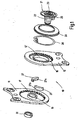
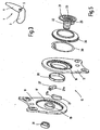
- eine Explosionsdarstellung des Ausführungsbeispiels,
- Fig. 2
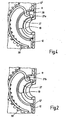
- teilweise geschnittene Teilansicht des Ausführungsbeispiels,
- Fig. 3
- eine schematische Darstellung eines Fahrzeugsitzes
- Fig. 4
- eine teilweise geschnittene Teilansicht eines bekannten Beschlags, und
- Fig. 5
- eine Explosionsdarstellung des bekannten Beschlags.
- Fig. 1
- an exploded view of the embodiment,
- Fig. 2
- partially sectioned partial view of the embodiment,
- Fig. 3
- a schematic representation of a vehicle seat
- Fig. 4
- a partially sectioned partial view of a known fitting, and
- Fig. 5
- an exploded view of the known fitting.
Ein Fahrzeugsitz 1 für ein Kraftfahrzeug weist ein Sitzteil 3 und eine relativ zum Sitzteil 3 in ihrer Neigung einstellbare Lehne 4 auf. Ein für die Neigungseinstellung manuell zu betätigendes Handrad 5 auf einer Seite des Fahrzeugsitzes 1 dreht eine nicht näher dargestellte Antriebswelle, welche horizontal im Übergangsbereich zwischen Sitzteil 3 und Lehne 4 angeordnet ist und auf beiden Seiten des Fahrzeugsitzes 1 drehfest in je einen Beschlag 10 eingreift. Die Lehne 4 ist mittels der beiden Beschläge 10 mit dem Sitzteil 3 verbunden. Von den beiden Ausführungsbeispielen des Beschlags 10 sind zunächst die gemeinsamen Merkmale beschrieben.A vehicle seat 1 for a motor vehicle has a seat part 3 and a
Der Beschlag 10 ist als Getriebebeschlag ausgebildet, bei welchem ein erstes Beschlagteil 11 und ein zweites Beschlagteil 12 über ein als (vorzugsweise wenigstens bei einem der beiden Beschläge 10 des Fahrzeugsitzes 1 selbsthemmendes) Exzenterumlaufgetriebe ausgebildetes Getriebe zum Verstellen und Feststellen miteinander verbunden sind. Die beiden Beschlagteile 11 und 12 bestehen aus Stahl und können bereichsweise gehärtet sein. Die beiden Beschlagteile 11 und 12 weisen eine im wesentlichen flache Form auf. Das erste Beschlagteil 11 ist fest mit der das Handrad 5 und die Antriebswelle lagernden Struktur (vorliegend der Struktur der Lehne 4) verbunden, weshalb im Ausführungsbeispiel das erste Bauteil 11 lehnenfest und daher in der Zeichnung oben dargestellt ist. Entsprechend ist das zweite Beschlagteil 12 im Ausführungsbeispiel sitzteilfest, d.h. mit der Struktur des Sitzteiles 3 verbunden, und in der Zeichnung unten dargestellt. Die Positionen der Beschlagteile 11 und 12 können je nach Anforderung ausgetauscht sein.The fitting 10 is designed as a geared fitting, in which a first
Zur Ausbildung des Getriebes ist am zweiten Beschlagteil 12 ein Zahnrad 16 mit einer Außenverzahnung und am ersten Beschlagteil 11 ein Zahnkranz 17 mit einer Innenverzahnung ausgeprägt, welche miteinander kämmen. Der Durchmesser des Kopfkreises der Außenverzahnung des Zahnrads 16 ist um wenigstens eine Zahnhöhe kleiner als der Durchmesser des Fußkreises der Innenverzahnung des Zahnkranzes 17. Der entsprechende Unterschied der Zähneanzahl von Zahnrad 16 und Zahnkranz 17 ermöglicht eine Abwälzbewegung des Zahnkranzes 17 am Zahnrad 16.To form the transmission, a
Das erste Beschlagteil 11 weist auf der dem Zahnrad 16 zugewandten Seite konzentrisch zur Innenverzahnung des Zahnkranzes 17 einen Kragenzug 19 auf. Der Kragenzug 19 ist ein angeformter Bestandteil des ersten Beschlagteils 11, also einstückig mit diesem ausgebildet. Im Kragenzug 19 ist mit Spiel ein Mitnehmer 21 mittels eines Buchsenabschnitts 22 gelagert. Der aus Kunststoff bestehende Mitnehmer 21, durch dessen Anordnung die verwendeten Richtungsangaben definiert sind, ist zentral mit einer zu einem Keilwellenprofil der Antriebswelle passenden, axial verlaufenden Bohrung 23 versehen. Ferner weist der Mitnehmer 21 ein angeformtes Mitnehmersegment 25 auf, welches sichelförmig um einen Teil des Kragenzuges 19 herum angeordnet ist. Zwei metallische Keilsegmente 27 liegen - zur Lagerung am ersten Beschlagteils 11 - mit ihrer gekrümmten Innenseiten 27a direkt am Kragenzug 19 des ersten Beschlagteils 11 und - zur Lagerung am zweiten Beschlagteil 12 - mit ihren gekrümmten Außenseiten 27b wenigstens indirekt am zweiten Beschlagteil 12 an, welcher hierfür ebenfalls einen - wenn auch kurzen - Kragenzug 12' aufweist. Der Kragenzug 12' ist ein angeformter Bestandteil des zweiten Beschlagteils 12, also einstückig mit diesem ausgebildet. Dabei lagert das zweite Beschlagteil 12 direkt mit seinem Kragenzug 12' die Keilsegmente 27, während im Stand der Technik hierfür ein in den Kragenzug 12' eingepresstes, buchsenförmiges Gleitlager 28 vorgesehen ist.The first
Das Mitnehmersegment 25 fasst mit Spiel zwischen die Schmalseiten der Keilsegmente 27, während die einander zugekehrten Breitseiten der Keilsegmente 27 jeweils einen abgewinkelten Endfinger einer Feder, im folgenden als Omegafeder 30 bezeichnet, abstützen. Die Omegafeder 30 drückt die Keilsegmente 27 in Umfangsrichtung auseinander und stellt damit den Beschlag 10 im Ruhezustand spielfrei. Der Mitnehmer 21 wird auf der Außenseite des ersten Beschlagteils 11 durch einen aufgeclipsten Sicherungsring 31 axial gesichert. Ein Dichtring 33, vorzugsweise aus Gummi, deckt den Bereich zwischen der Außenseite des zweiten Beschlagteils 12 und einem als Abdeckscheibe ausgebildeten Bereich des Mitnehmers 21 ab. Zur Aufnahme der axial wirkenden Kräfte ist in an sich bekannter Weise an den beiden Beschlagteilen 11 und 12 je ein in der Zeichnung nicht dargestelltes Halteblech angeschweißt, welches das jeweils andere Beschlagteil übergreift, ohne die Einstellbewegung zu behindern.The
Durch das Mitnehmersegment 25 und die Keilsegmente 27 wird ein Exzenter definiert, welcher in Verlängerung der Richtung der Exzentrizität das Zahnrad 16 und den Zahnkranz 17 an einer so definierten Eingriffsstelle ineinander drückt. Bei einem Antrieb durch die sich drehende Antriebswelle wird ein Drehmoment zunächst auf den Mitnehmer 21 und dann auf den so definierten Exzenter übertragen, welcher entlang der Innenseite des Kragenzugs 12' gleitet unter Verlagerung der Richtung der Exzentrizität und damit unter Verlagerung der Eingriffsstelle des Zahnrades 16 im Zahnkranz 17, was sich als taumelnde Abwälzbewegung der Beschlagteile 11 und 12 aneinander darstellt.By the
Sowohl für das Sperren des Beschlags 10 im Ruhezustand als auch für den Wirkungsgrad im Betrieb spielen die Reibungsverhältnisse eine wichtige Rolle. Es ist dabei im Stand der Technik bekannt, dass die Keilsegmente 27 auf ihrer Außenseite 27b aufgrund des Gleitlagers 28 eine deutlich kleinere Reibung erfahren als auf ihrer Innenseite 27a, wobei die Verhältnisse theoretisch auch genau umgekehrt sein könnten. Erfindungsgemäß werden nun Verbesserungen an den Reibungsverhältnissen vorgenommen.Both for the locking of the fitting 10 at rest and for the efficiency in operation, the friction conditions play an important role. It is known in the prior art that the
Die Innenseite 27a der Keilsegmente 27 ist mit einer superharten, ersten amorphen Kohlenstoffschicht, vorliegend mit einer Schichtdicke im Mikrometerbereich, beschichtet. Die amorphe Kohlenstoffschicht verbindet die Härte von Diamant mit niedrigen Reibwerten, wobei die Schwankungsbreite des Reibwertes sehr gering ist. Der Reibwert der dünnen amorphen Kohlenstoffschicht ist geringer als der Reibwert des Materials der Keilsegmente 27, welche im wesentlichen aus gehärtetem Stahl oder einem Sintermaterial bestehen. Die Reibung zwischen den Keilsegmenten 27 und dem ersten Beschlagteil 11, d.h. dessen Kragenzug 19, kann dadurch - bis nahe an die Grenze der Selbsthemmung gebracht werden, welche für das Sperren des Beschlags 10 sorgt. Der Wirkungsgrad des Beschlags 10 kann mit dieser verringerten Reibung von etwa 0,3 auf knapp 0,5 erhöht werden.The
Erfindungsgemäß ist - unabhängig vom Vorhandensein der ersten amorphen Kohlenstoffschicht- die Außenseite 27b der Keilsegmente 27 mit einer zweiten amorphen Kohlenstoffschicht, vorliegend mit einer Schichtdicke im Mikrometerbereich, beschichtet, deren Reibwert geringer ist als derjenige der ersten amorphen Kohlenstoffschicht und etwa so hoch wie derjenige eines aus dem Stand der Technik bekannten Gleitlagers 28 eingestellt ist. Es braucht daher kein Gleitlager 28 vorgesehen sein, da die direkte Reibung zwischen den Keilsegmenten 27 mit der zweiten amorphen Kohlenstoffschicht auf der Außenseite 27b und dem zweiten Beschlagteil 12 einen sehr kleinen Wert annimmt. Zudem kann ohne Gleitlager 28 im Crashfall keine plastische Verformung des Gleitlagers 28 als einzigem ungehärtetem Bauteil im Kraftfluss auftreten. Der durch den Entfall des Gleitlagers 28 eingesparte radiale Bauraum kann den anderen Bauteilen zugefügt werden, vorzugsweise den Keilsegmenten 27, und erhöht damit die Festigkeit des Beschlags 10 bei gleichbleibendem Gesamtbauraum.According to the invention - regardless of the presence of the first amorphous carbon layer, the
Es sind nun verschiedene Abwandlungen möglich. So kann die erste amorphe Kohlenstoffschicht auf dem Kragenzug 19 des ersten Beschlagteils 11 statt auf den Keilsegmenten 27 aufgebracht sein. Die zweite amorphe Kohlenstoffschicht kann bei entsprechender Einstellung mit sehr geringer Reibung direkt am zweiten Beschlagteil 12 vorgesehen sein, auch unabhängig vom Vorhandensein der ersten amorphen Kohlenstoffschicht, womit jeweils ein Gleitlager 28 entfallen kann. Die Kragenzüge 12' und/oder 19 können gehärtet sein.There are now various modifications possible. Thus, the first amorphous carbon layer may be applied to the
Es sind auch Abwandlungen denkbar, bei denen die Reibung zwischen dem ersten Beschlagteil 11 und wenigstens dem höher belasteten (aufgrund des Gewichtes der Lehne 10) Keilsegment 27 durch die erste amorphe Kohlenstoffschicht (unter Umständen deutlich) unter die Selbsthemmgrenze gebracht wird, beispielsweise durch eine beidseitige oder Rundumbeschichtung des betreffenden Keilsegmentes 27. Die Selbsthemmung des Beschlags 10 ist dann beispielsweise durch eine schaltbare Bremse, beispielsweise eine Schlingfederbremse oder ein Klemmrollenfreilauf, aufzubringen.Variations are also conceivable in which the friction between the first
Es sind schließlich auf Abwandlungen möglich, bei denen der Mitnehmer 21 entsprechend der
- 11
- Fahrzeugsitzvehicle seat
- 33
- Sitzteilseat part
- 44
- Lehnerest
- 55
- Handradhandwheel
- 1010
- Beschlagfitting
- 1111
- erstes Beschlagteilfirst fitting part
- 1212
- zweites Beschlagteilsecond fitting part
- 12'12 '
- Kragenzug des zweiten BeschlagteilsCollar of the second fitting part
- 1616
- Zahnradgear
- 1717
- Zahnkranzsprocket
- 1919
- Kragenzug (des ersten Beschlagteils)Collar pull (of the first fitting part)
- 2121
- Mitnehmertakeaway
- 2222
- Buchsenabschnittbushing section
- 2323
- Bohrungdrilling
- 2525
- Mitnehmersegmentdriving segment
- 2727
- Keilsegmentwedge segment
- 27a27a
- Innenseiteinside
- 27b27b
- Außenseiteoutside
- 2828
- Gleitlagerbearings
- 3030
- OmegafederOmega spring
- 3131
- Sicherungsringcirclip
- 3333
- Dichtringseal
Claims (11)
- A fitting for a vehicle seat, in particular for a motor vehicle seat, witha) a first fitting part (11),b) a second fitting part (12) in geared connection with the first fitting part (11), andc) a multi-part eccentric which is mounted rotatably in the first fitting part (11) and is intended for driving a rolling movement of first fitting part (11) and second fitting part (12) on each other,
whereind) the eccentric comprises, as components (21, 27), at least one driver (21) and wedge segments (27) and, for the mounting of the eccentric, the components (21, 27) bearing at least indirectly by means of their inner side (27a) and/or their outer side (27b) in each case against one of the fitting parts (11 or 12),
characterized in thate) at least one component (27) of the eccentric is mounted with its outer side (27b) on the second fitting part (12) and interacting directly with the second fitting part (12), as the component (27) of the eccentric bears, by means of its outer side (27b), against an integrally formed component, in particular a collar formation (12') of the second fitting part (12), directly and free from pressed-in slide bearings or rolling bearings, andf) said component (27) of the eccentric or the associated fitting part (11 and/or 12), in the interacting region, is coated with a thin layer which has a lower coefficient of friction than the material of the component (27). - A fitting for a vehicle seat, in particular for a motor vehicle seat, witha) a first fitting part (11),b) a second fitting part (12) in geared connection with the first fitting part (11), andc) a multi-part eccentric which is mounted rotatably in the first fitting part (11) and is intended for driving a rolling movement of first fitting part (11) and second fitting part (12) on each other,
whereind) the eccentric comprises, as components (21, 27), at least one driver (21) and wedge segments (27) and, for the mounting of the eccentric, the components (21, 27) bearing at least indirectly by means of their inner side (27a) and/or their outer side (27b) in each case against one of the fitting parts (11 or 12),
characterized in thate) at least one component (27) of the eccentric is mounted with its inner side (27a) on the first fitting part (11) and interacting directly with the first fitting part (11), as the component (27) of the eccentric bears, by means of its inner side (27a), against an integrally formed component, in particular a collar formation (19) of the first fitting part (11), directly and free from pressed-in slide bearings or rolling bearings, andf) said component (27) of the eccentric or the associated fitting part (11 and/or 12), in the interacting region, is coated with a thin layer which has a lower coefficient of friction than the material of the component (27). - The fitting as claimed in one of the preceding claims, characterized in that the components (27) of the eccentric are coated on the sides (27a, 27b) which face away from each other or on the associated fitting parts (11 and/or 12), in the region interacting with the components (27), with a thin layer which has a lower coefficient of friction than the material of the component (27).
- The fitting as claimed in one of the preceding claims, characterized in that the thin layer is an amorphous carbon layer which, in particular, is crosslinked tetrahedrically.
- The fitting as claimed in claim 4, characterized in that the amorphous carbon layer has a layer thickness in the micrometer range or less.
- The fitting as claimed in claim 4 or 5, characterized in that the component (27) of the eccentric has, on its inner side (27a), or the associated fitting part (11), in the region interacting with the component (27), has a first amorphous carbon layer, and the component or a further component (27) of the eccentric has, on its outer side (27b), or the associated fitting part (12) has, in the region interacting with the component (27), a second amorphous carbon layer.
- The fitting as claimed in claim 6, characterized in that the two amorphous carbon layers have different coefficients of friction.
- The fitting as claimed in one of the preceding claims, characterized in that the driver (21) is of multi-part design and has a driving ring as a component of the eccentric, which driving ring bears, on the one hand, against the wedge segments (27) and, on the other hand, against the associated fitting part (11 or 12).
- The fitting as claimed in one of the preceding claims, characterized in that the wedge segments (27) and/or the driving ring are essentially composed of hardened steel or a sintered material.
- The fitting as claimed in one of the preceding claims, characterized in that the thin layer is a sliding layer of high-performance plastic, in particular of PEEK, and/or is a PTFE sliding layer.
- A vehicle seat, in particular motor vehicle seat, with a seat part (3) and a backrest (4) which can be adjusted in its inclination relative to the seat part (3) and is attached to the seat part (3) on at least one side of the vehicle seat (1) by means of a fitting (10) as claimed in one of the preceding claims.
Priority Applications (1)
| Application Number | Priority Date | Filing Date | Title |
|---|---|---|---|
| PL06828916T PL1948472T3 (en) | 2005-11-16 | 2006-11-03 | Fitting for a vehicle seat |
Applications Claiming Priority (2)
| Application Number | Priority Date | Filing Date | Title |
|---|---|---|---|
| DE102005054489A DE102005054489B4 (en) | 2005-11-16 | 2005-11-16 | Fitting for a vehicle seat |
| PCT/EP2006/010551 WO2007057105A2 (en) | 2005-11-16 | 2006-11-03 | Fitting for a vehicle seat |
Publications (2)
| Publication Number | Publication Date |
|---|---|
| EP1948472A2 EP1948472A2 (en) | 2008-07-30 |
| EP1948472B1 true EP1948472B1 (en) | 2010-05-19 |
Family
ID=37730331
Family Applications (1)
| Application Number | Title | Priority Date | Filing Date |
|---|---|---|---|
| EP06828916A Expired - Fee Related EP1948472B1 (en) | 2005-11-16 | 2006-11-03 | Fitting for a vehicle seat |
Country Status (8)
| Country | Link |
|---|---|
| US (1) | US20080193203A1 (en) |
| EP (1) | EP1948472B1 (en) |
| JP (1) | JP5236479B2 (en) |
| KR (1) | KR101338161B1 (en) |
| BR (1) | BRPI0618579A2 (en) |
| DE (3) | DE102005054489B4 (en) |
| PL (1) | PL1948472T3 (en) |
| WO (2) | WO2007057105A2 (en) |
Families Citing this family (9)
| Publication number | Priority date | Publication date | Assignee | Title |
|---|---|---|---|---|
| DE102008036647A1 (en) | 2007-11-28 | 2009-06-04 | C. Rob. Hammerstein Gmbh & Co. Kg | Wobble joint fitting for a vehicle seat comprises a spring having a support region which divides the spring into two regions |
| JP5414299B2 (en) | 2008-03-04 | 2014-02-12 | ツェー ロブ ハメルステイン ゲーエムベーハー ウント コー カーゲー | Swing joint parts for automobile seat adjusters, especially for back hinge parts |
| DE102009005044A1 (en) | 2009-01-14 | 2010-07-15 | Brose Fahrzeugteile Gmbh & Co. Kommanditgesellschaft, Coburg | Adjustment device for adjusting a vehicle seat part |
| DE102009014115A1 (en) * | 2009-03-24 | 2010-09-30 | Faurecia Autositze Gmbh | Gearing mechanism, for adjustment of the pitch of a motor vehicle seat backrest, has separate outer/inner components with inner/outer teeth and an eccentric to set the inner unit |
| DE102010062414B4 (en) | 2009-12-22 | 2022-06-23 | Keiper Seating Mechanisms Co., Ltd. | Wobble joint fitting for an adjustment device of a motor vehicle seat, in particular for a backrest joint fitting |
| FR2991928B1 (en) * | 2012-06-19 | 2014-06-20 | Faurecia Sieges Automobile | ADJUSTING MECHANISM FOR A VEHICLE SEAT, VEHICLE SEAT COMPRISING SUCH A MECHANISM |
| DE102013009272A1 (en) * | 2013-03-26 | 2014-10-02 | Johnson Controls Components Gmbh & Co. Kg | Adjusting device and method for producing an adjusting device |
| US9475409B2 (en) * | 2013-06-17 | 2016-10-25 | Hubei Aviation Precision Machinery Technology Co., Ltd. | Seat recliner and oil collecting element |
| KR102001507B1 (en) * | 2017-12-26 | 2019-07-18 | 현대트랜시스(주) | Seat recliner for vehicle |
Family Cites Families (20)
| Publication number | Priority date | Publication date | Assignee | Title |
|---|---|---|---|---|
| DE3941215C2 (en) * | 1989-12-14 | 1995-07-20 | Keiper Recaro Gmbh Co | Backrest adjustment fitting for seats, in particular motor vehicle seats |
| DE4436101C5 (en) * | 1993-11-30 | 2008-12-11 | Keiper Gmbh & Co.Kg | Lehneneinstellbeschlag for seats with adjustable backrest, in particular motor vehicle seats |
| IT1267395B1 (en) * | 1994-02-21 | 1997-02-05 | Olivetti Canon Ind Spa | CLEANING DEVICE FOR FIXING UNIT |
| US5524970A (en) * | 1994-08-10 | 1996-06-11 | Hoover Universal, Inc. | Rotary recliner |
| DE19548809C1 (en) * | 1995-12-27 | 1997-05-22 | Keiper Recaro Gmbh Co | Adjustment and fixture device for road vehicle seat |
| DE19729562A1 (en) * | 1996-07-17 | 1998-01-22 | Volkswagen Ag | Vehicle seat backrest adjustment gearing |
| DE19938666C5 (en) * | 1999-08-14 | 2008-01-03 | Keiper Gmbh & Co.Kg | Adjustable fitting for seats with reclining backrest, in particular for motor vehicle seats |
| JP4730753B2 (en) * | 2000-03-23 | 2011-07-20 | 株式会社神戸製鋼所 | Diamond-like carbon hard multilayer film and members with excellent wear resistance and sliding resistance |
| DE20104280U1 (en) * | 2001-03-13 | 2001-07-26 | Trw Repa Gmbh | Foot protection device |
| DE10144840B4 (en) * | 2001-09-06 | 2006-11-09 | Keiper Gmbh & Co.Kg | Fitting for a vehicle seat |
| EP1423294B1 (en) * | 2001-09-06 | 2007-05-16 | KEIPER GmbH & Co. KG | Fitting for a vehicle seat |
| ES2266382T3 (en) * | 2002-10-24 | 2007-03-01 | TETRA LAVAL HOLDINGS & FINANCE S.A. | WELDING GRIP. |
| DE10328300B4 (en) * | 2003-06-23 | 2006-09-21 | Faurecia Autositze Gmbh & Co. Kg | Adjustment fitting for motor vehicle seat |
| DE10340997B3 (en) * | 2003-09-05 | 2005-01-13 | Keiper Gmbh & Co. Kg | Rotary drive for adjusting vehicle seat has transmission shifted to smaller transmission ratio by service element |
| KR100549199B1 (en) * | 2003-11-26 | 2006-02-02 | 주식회사다스 | Reclining device for seat assembly of vehicle |
| DE102004007043B3 (en) * | 2004-02-12 | 2005-06-23 | Keiper Gmbh & Co. Kg | Mounting for backrest of automobile passenger seat adjusted via driven eccentric provided by ring enclosing 2 wedge segments which are biased together |
| DE102004011268B3 (en) * | 2004-03-09 | 2005-09-22 | Faurecia Autositze Gmbh & Co. Kg | Tilt adjustment fitting for the backrest of a motor vehicle seat |
| DE102004013272B3 (en) * | 2004-03-18 | 2006-01-26 | Faurecia Autositze Gmbh & Co. Kg | Tilt adjustment fitting for the backrest of a motor vehicle seat |
| DE102005026658B3 (en) * | 2005-06-09 | 2006-11-02 | Faurecia Autositze Gmbh & Co. Kg | Inclination adjustment fitting for vehicle seat, has contact cam serving for load transmission, over larger contact surface of cam, from fitting part connected with backrest onto another fitting part connected with seat part |
| US7314250B1 (en) * | 2006-09-27 | 2008-01-01 | Keiper Gmbh & Co. Kg | Fitting system for a vehicle seat |
-
2005
- 2005-11-16 DE DE102005054489A patent/DE102005054489B4/en not_active Expired - Fee Related
-
2006
- 2006-11-03 DE DE502006006995T patent/DE502006006995D1/en active Active
- 2006-11-03 WO PCT/EP2006/010551 patent/WO2007057105A2/en active Application Filing
- 2006-11-03 EP EP06828916A patent/EP1948472B1/en not_active Expired - Fee Related
- 2006-11-03 JP JP2008540485A patent/JP5236479B2/en not_active Expired - Fee Related
- 2006-11-03 BR BRPI0618579-7A patent/BRPI0618579A2/en not_active Application Discontinuation
- 2006-11-03 WO PCT/EP2006/010550 patent/WO2007057104A2/en active Application Filing
- 2006-11-03 DE DE112006002929T patent/DE112006002929A5/en not_active Ceased
- 2006-11-03 KR KR1020087005350A patent/KR101338161B1/en not_active IP Right Cessation
- 2006-11-03 PL PL06828916T patent/PL1948472T3/en unknown
-
2008
- 2008-04-16 US US12/148,090 patent/US20080193203A1/en not_active Abandoned
Also Published As
| Publication number | Publication date |
|---|---|
| DE502006006995D1 (en) | 2010-07-01 |
| WO2007057105A3 (en) | 2007-08-30 |
| WO2007057104A2 (en) | 2007-05-24 |
| WO2007057104A3 (en) | 2007-08-30 |
| JP2009515616A (en) | 2009-04-16 |
| DE102005054489A1 (en) | 2007-05-24 |
| KR20080067326A (en) | 2008-07-18 |
| DE102005054489B4 (en) | 2008-01-31 |
| EP1948472A2 (en) | 2008-07-30 |
| US20080193203A1 (en) | 2008-08-14 |
| JP5236479B2 (en) | 2013-07-17 |
| BRPI0618579A2 (en) | 2011-09-06 |
| DE112006002929A5 (en) | 2008-10-09 |
| PL1948472T3 (en) | 2010-08-31 |
| KR101338161B1 (en) | 2013-12-06 |
| WO2007057105A2 (en) | 2007-05-24 |
Similar Documents
| Publication | Publication Date | Title |
|---|---|---|
| EP1948472B1 (en) | Fitting for a vehicle seat | |
| DE102005028779B4 (en) | Fitting for a vehicle seat | |
| EP1713659B1 (en) | Fitting for a vehicle seat | |
| EP1647438B1 (en) | Geared fitting for a vehicle seat | |
| EP1423294B1 (en) | Fitting for a vehicle seat | |
| EP1951443B1 (en) | Component, especially a preform, comprising a coating | |
| EP1943439B1 (en) | Belt tensioner | |
| EP1720729B1 (en) | Fitting for a motor vehicle seat | |
| DE102009011462B4 (en) | Fitting for a vehicle seat and vehicle seat | |
| DE202009017811U1 (en) | Fitting for a vehicle seat | |
| DE102010019361B3 (en) | Fitting for a vehicle seat and vehicle seat | |
| EP1202870A1 (en) | Adjustment armature for seats, especially motor vehicle seats, with an adjustable inclinable backrest | |
| WO2007134705A2 (en) | Gear train for an actuator | |
| DE102010018952B4 (en) | Fitting for a vehicle seat, vehicle seat and method for assembling a fitting | |
| EP2419296A2 (en) | Drive unit for a vehicle seat | |
| EP1917157B1 (en) | Eccentricity gear step | |
| DE10144840A1 (en) | Fitting for a motor vehicle seat comprises a driving pin and a driving ring connected to each other in a form-locking manner by a transmission profile | |
| EP2734411A1 (en) | Seat fitting for a motor vehicle seat | |
| DE3723710A1 (en) | SWIVEL JOINT FOR SEATS WITH ADJUSTABLE BACKREST | |
| DE102009053250B4 (en) | Fitting for a vehicle seat and vehicle seat | |
| DE10203006B4 (en) | Fitting for a vehicle seat | |
| EP1813466B1 (en) | Joint fitting | |
| DE4428557A1 (en) | Pivot joint | |
| DE10110668B4 (en) | Kurvennuttrieb | |
| EP1102909A1 (en) | Coupling device for joining a door stop to the hinge of door of a motor vehicle |
Legal Events
| Date | Code | Title | Description |
|---|---|---|---|
| PUAI | Public reference made under article 153(3) epc to a published international application that has entered the european phase |
Free format text: ORIGINAL CODE: 0009012 |
|
| 17P | Request for examination filed |
Effective date: 20080220 |
|
| AK | Designated contracting states |
Kind code of ref document: A2 Designated state(s): DE FR GB PL |
|
| DAX | Request for extension of the european patent (deleted) | ||
| RBV | Designated contracting states (corrected) |
Designated state(s): DE FR GB PL |
|
| 17Q | First examination report despatched |
Effective date: 20081215 |
|
| GRAP | Despatch of communication of intention to grant a patent |
Free format text: ORIGINAL CODE: EPIDOSNIGR1 |
|
| GRAS | Grant fee paid |
Free format text: ORIGINAL CODE: EPIDOSNIGR3 |
|
| GRAA | (expected) grant |
Free format text: ORIGINAL CODE: 0009210 |
|
| AK | Designated contracting states |
Kind code of ref document: B1 Designated state(s): DE FR GB PL |
|
| REG | Reference to a national code |
Ref country code: GB Ref legal event code: FG4D Free format text: NOT ENGLISH |
|
| REF | Corresponds to: |
Ref document number: 502006006995 Country of ref document: DE Date of ref document: 20100701 Kind code of ref document: P |
|
| REG | Reference to a national code |
Ref country code: PL Ref legal event code: T3 |
|
| PLBE | No opposition filed within time limit |
Free format text: ORIGINAL CODE: 0009261 |
|
| STAA | Information on the status of an ep patent application or granted ep patent |
Free format text: STATUS: NO OPPOSITION FILED WITHIN TIME LIMIT |
|
| 26N | No opposition filed |
Effective date: 20110222 |
|
| REG | Reference to a national code |
Ref country code: DE Ref legal event code: R097 Ref document number: 502006006995 Country of ref document: DE Effective date: 20110221 |
|
| REG | Reference to a national code |
Ref country code: DE Ref legal event code: R082 Ref document number: 502006006995 Country of ref document: DE |
|
| REG | Reference to a national code |
Ref country code: DE Ref legal event code: R081 Ref document number: 502006006995 Country of ref document: DE Owner name: JOHNSON CONTROLS COMPONENTS GMBH & CO. KG, DE Free format text: FORMER OWNER: KEIPER GMBH & CO. KG, 67657 KAISERSLAUTERN, DE Effective date: 20140710 Ref country code: DE Ref legal event code: R081 Ref document number: 502006006995 Country of ref document: DE Owner name: ADIENT LUXEMBOURG HOLDING S.A.R.L., LU Free format text: FORMER OWNER: KEIPER GMBH & CO. KG, 67657 KAISERSLAUTERN, DE Effective date: 20140710 Ref country code: DE Ref legal event code: R081 Ref document number: 502006006995 Country of ref document: DE Owner name: ADIENT LUXEMBOURG HOLDING S.A R.L., LU Free format text: FORMER OWNER: KEIPER GMBH & CO. KG, 67657 KAISERSLAUTERN, DE Effective date: 20140710 |
|
| REG | Reference to a national code |
Ref country code: FR Ref legal event code: PLFP Year of fee payment: 10 |
|
| PGFP | Annual fee paid to national office [announced via postgrant information from national office to epo] |
Ref country code: GB Payment date: 20151118 Year of fee payment: 10 |
|
| PGFP | Annual fee paid to national office [announced via postgrant information from national office to epo] |
Ref country code: FR Payment date: 20151119 Year of fee payment: 10 |
|
| REG | Reference to a national code |
Ref country code: DE Ref legal event code: R081 Ref document number: 502006006995 Country of ref document: DE Owner name: ADIENT LUXEMBOURG HOLDING S.A.R.L., LU Free format text: FORMER OWNER: JOHNSON CONTROLS COMPONENTS GMBH & CO. KG, 67657 KAISERSLAUTERN, DE Ref country code: DE Ref legal event code: R081 Ref document number: 502006006995 Country of ref document: DE Owner name: ADIENT LUXEMBOURG HOLDING S.A R.L., LU Free format text: FORMER OWNER: JOHNSON CONTROLS COMPONENTS GMBH & CO. KG, 67657 KAISERSLAUTERN, DE |
|
| PGFP | Annual fee paid to national office [announced via postgrant information from national office to epo] |
Ref country code: PL Payment date: 20161027 Year of fee payment: 11 |
|
| GBPC | Gb: european patent ceased through non-payment of renewal fee |
Effective date: 20161103 |
|
| REG | Reference to a national code |
Ref country code: FR Ref legal event code: ST Effective date: 20170731 |
|
| PG25 | Lapsed in a contracting state [announced via postgrant information from national office to epo] |
Ref country code: FR Free format text: LAPSE BECAUSE OF NON-PAYMENT OF DUE FEES Effective date: 20161130 |
|
| PG25 | Lapsed in a contracting state [announced via postgrant information from national office to epo] |
Ref country code: GB Free format text: LAPSE BECAUSE OF NON-PAYMENT OF DUE FEES Effective date: 20161103 |
|
| PGFP | Annual fee paid to national office [announced via postgrant information from national office to epo] |
Ref country code: DE Payment date: 20171130 Year of fee payment: 12 |
|
| REG | Reference to a national code |
Ref country code: DE Ref legal event code: R081 Ref document number: 502006006995 Country of ref document: DE Owner name: ADIENT LUXEMBOURG HOLDING S.A R.L., LU Free format text: FORMER OWNER: ADIENT LUXEMBOURG HOLDING S.A.R.L., LUXEMBOURG, LU |
|
| PG25 | Lapsed in a contracting state [announced via postgrant information from national office to epo] |
Ref country code: PL Free format text: LAPSE BECAUSE OF NON-PAYMENT OF DUE FEES Effective date: 20171103 |
|
| REG | Reference to a national code |
Ref country code: DE Ref legal event code: R119 Ref document number: 502006006995 Country of ref document: DE |
|
| PG25 | Lapsed in a contracting state [announced via postgrant information from national office to epo] |
Ref country code: DE Free format text: LAPSE BECAUSE OF NON-PAYMENT OF DUE FEES Effective date: 20190601 |