EP1947744A2 - Power supply circuit connector and method of connecting power supply circuit - Google Patents
Power supply circuit connector and method of connecting power supply circuit Download PDFInfo
- Publication number
- EP1947744A2 EP1947744A2 EP08000377A EP08000377A EP1947744A2 EP 1947744 A2 EP1947744 A2 EP 1947744A2 EP 08000377 A EP08000377 A EP 08000377A EP 08000377 A EP08000377 A EP 08000377A EP 1947744 A2 EP1947744 A2 EP 1947744A2
- Authority
- EP
- European Patent Office
- Prior art keywords
- lever
- housing
- power supply
- supply circuit
- connector
- Prior art date
- Legal status (The legal status is an assumption and is not a legal conclusion. Google has not performed a legal analysis and makes no representation as to the accuracy of the status listed.)
- Granted
Links
Images






Classifications
-
- H—ELECTRICITY
- H01—ELECTRIC ELEMENTS
- H01R—ELECTRICALLY-CONDUCTIVE CONNECTIONS; STRUCTURAL ASSOCIATIONS OF A PLURALITY OF MUTUALLY-INSULATED ELECTRICAL CONNECTING ELEMENTS; COUPLING DEVICES; CURRENT COLLECTORS
- H01R13/00—Details of coupling devices of the kinds covered by groups H01R12/70 or H01R24/00 - H01R33/00
- H01R13/62—Means for facilitating engagement or disengagement of coupling parts or for holding them in engagement
- H01R13/629—Additional means for facilitating engagement or disengagement of coupling parts, e.g. aligning or guiding means, levers, gas pressure electrical locking indicators, manufacturing tolerances
- H01R13/62933—Comprising exclusively pivoting lever
- H01R13/62938—Pivoting lever comprising own camming means
-
- H—ELECTRICITY
- H01—ELECTRIC ELEMENTS
- H01H—ELECTRIC SWITCHES; RELAYS; SELECTORS; EMERGENCY PROTECTIVE DEVICES
- H01H85/00—Protective devices in which the current flows through a part of fusible material and this current is interrupted by displacement of the fusible material when this current becomes excessive
- H01H85/54—Protective devices wherein the fuse is carried, held, or retained by an intermediate or auxiliary part removable from the base, or used as sectionalisers
- H01H85/547—Protective devices wherein the fuse is carried, held, or retained by an intermediate or auxiliary part removable from the base, or used as sectionalisers with sliding fuse carrier
-
- H—ELECTRICITY
- H01—ELECTRIC ELEMENTS
- H01H—ELECTRIC SWITCHES; RELAYS; SELECTORS; EMERGENCY PROTECTIVE DEVICES
- H01H9/00—Details of switching devices, not covered by groups H01H1/00 - H01H7/00
- H01H9/08—Arrangements to facilitate replacement of a switch, e.g. cartridge housing
- H01H9/085—Arrangements to facilitate replacement of a switch, e.g. cartridge housing contact separation effected by removing contact carrying element
-
- H—ELECTRICITY
- H01—ELECTRIC ELEMENTS
- H01R—ELECTRICALLY-CONDUCTIVE CONNECTIONS; STRUCTURAL ASSOCIATIONS OF A PLURALITY OF MUTUALLY-INSULATED ELECTRICAL CONNECTING ELEMENTS; COUPLING DEVICES; CURRENT COLLECTORS
- H01R13/00—Details of coupling devices of the kinds covered by groups H01R12/70 or H01R24/00 - H01R33/00
- H01R13/62—Means for facilitating engagement or disengagement of coupling parts or for holding them in engagement
- H01R13/629—Additional means for facilitating engagement or disengagement of coupling parts, e.g. aligning or guiding means, levers, gas pressure electrical locking indicators, manufacturing tolerances
- H01R13/62933—Comprising exclusively pivoting lever
- H01R13/6295—Pivoting lever comprising means indicating incorrect coupling of mating connectors
-
- H—ELECTRICITY
- H01—ELECTRIC ELEMENTS
- H01R—ELECTRICALLY-CONDUCTIVE CONNECTIONS; STRUCTURAL ASSOCIATIONS OF A PLURALITY OF MUTUALLY-INSULATED ELECTRICAL CONNECTING ELEMENTS; COUPLING DEVICES; CURRENT COLLECTORS
- H01R13/00—Details of coupling devices of the kinds covered by groups H01R12/70 or H01R24/00 - H01R33/00
- H01R13/62—Means for facilitating engagement or disengagement of coupling parts or for holding them in engagement
- H01R13/629—Additional means for facilitating engagement or disengagement of coupling parts, e.g. aligning or guiding means, levers, gas pressure electrical locking indicators, manufacturing tolerances
- H01R13/62933—Comprising exclusively pivoting lever
- H01R13/62955—Pivoting lever comprising supplementary/additional locking means
-
- H—ELECTRICITY
- H01—ELECTRIC ELEMENTS
- H01R—ELECTRICALLY-CONDUCTIVE CONNECTIONS; STRUCTURAL ASSOCIATIONS OF A PLURALITY OF MUTUALLY-INSULATED ELECTRICAL CONNECTING ELEMENTS; COUPLING DEVICES; CURRENT COLLECTORS
- H01R13/00—Details of coupling devices of the kinds covered by groups H01R12/70 or H01R24/00 - H01R33/00
- H01R13/66—Structural association with built-in electrical component
- H01R13/70—Structural association with built-in electrical component with built-in switch
- H01R13/701—Structural association with built-in electrical component with built-in switch the switch being actuated by an accessory, e.g. cover, locking member
-
- H—ELECTRICITY
- H01—ELECTRIC ELEMENTS
- H01R—ELECTRICALLY-CONDUCTIVE CONNECTIONS; STRUCTURAL ASSOCIATIONS OF A PLURALITY OF MUTUALLY-INSULATED ELECTRICAL CONNECTING ELEMENTS; COUPLING DEVICES; CURRENT COLLECTORS
- H01R13/00—Details of coupling devices of the kinds covered by groups H01R12/70 or H01R24/00 - H01R33/00
- H01R13/66—Structural association with built-in electrical component
- H01R13/70—Structural association with built-in electrical component with built-in switch
- H01R13/71—Contact members of coupling parts operating as switch, e.g. linear or rotational movement required after mechanical engagement of coupling part to establish electrical connection
-
- H—ELECTRICITY
- H01—ELECTRIC ELEMENTS
- H01R—ELECTRICALLY-CONDUCTIVE CONNECTIONS; STRUCTURAL ASSOCIATIONS OF A PLURALITY OF MUTUALLY-INSULATED ELECTRICAL CONNECTING ELEMENTS; COUPLING DEVICES; CURRENT COLLECTORS
- H01R2201/00—Connectors or connections adapted for particular applications
- H01R2201/26—Connectors or connections adapted for particular applications for vehicles
-
- H—ELECTRICITY
- H01—ELECTRIC ELEMENTS
- H01R—ELECTRICALLY-CONDUCTIVE CONNECTIONS; STRUCTURAL ASSOCIATIONS OF A PLURALITY OF MUTUALLY-INSULATED ELECTRICAL CONNECTING ELEMENTS; COUPLING DEVICES; CURRENT COLLECTORS
- H01R33/00—Coupling devices specially adapted for supporting apparatus and having one part acting as a holder providing support and electrical connection via a counterpart which is structurally associated with the apparatus, e.g. lamp holders; Separate parts thereof
- H01R33/945—Holders with built-in electrical component
- H01R33/96—Holders with built-in electrical component with switch operated by engagement or disengagement of coupling
-
- H—ELECTRICITY
- H01—ELECTRIC ELEMENTS
- H01R—ELECTRICALLY-CONDUCTIVE CONNECTIONS; STRUCTURAL ASSOCIATIONS OF A PLURALITY OF MUTUALLY-INSULATED ELECTRICAL CONNECTING ELEMENTS; COUPLING DEVICES; CURRENT COLLECTORS
- H01R33/00—Coupling devices specially adapted for supporting apparatus and having one part acting as a holder providing support and electrical connection via a counterpart which is structurally associated with the apparatus, e.g. lamp holders; Separate parts thereof
- H01R33/97—Holders with separate means to prevent loosening of the coupling or unauthorised removal of apparatus held
-
- H—ELECTRICITY
- H01—ELECTRIC ELEMENTS
- H01R—ELECTRICALLY-CONDUCTIVE CONNECTIONS; STRUCTURAL ASSOCIATIONS OF A PLURALITY OF MUTUALLY-INSULATED ELECTRICAL CONNECTING ELEMENTS; COUPLING DEVICES; CURRENT COLLECTORS
- H01R33/00—Coupling devices specially adapted for supporting apparatus and having one part acting as a holder providing support and electrical connection via a counterpart which is structurally associated with the apparatus, e.g. lamp holders; Separate parts thereof
- H01R33/975—Holders with resilient means for protecting apparatus against vibrations or shocks
Definitions
- the present invention relates to a power supply circuit connector for breaking or connecting a power supply circuit of a hybrid car, an electric car and the like.
- the present invention also relates to a method of connecting the power supply circuit.
- the device of US6982393 has the following operations: Rotating a lever allows one connector housing to be received in another connector housing, thus connecting main circuit terminals with each other. Moreover, sliding the one connector housing in the another connector housing connects mated state sensor terminals, thereby bringing the power supply circuit into a conduction state.
- a power supply circuit connector of a power supply circuit comprising: a first housing including: a pair of main circuit terminals adapted to be connected with each other via a first switch terminal, for bringing a power supply circuit into a conduction state, and a pair of mated state sensor terminals adapted to be connected with each other, for bringing the power supply circuit into the conduction state; a second housing configured to mate with or to be detached from the first housing, the second housing including: the first switch terminal configured to connect the pair of the main circuit terminals by means of a lever rotated to a first certain position; the lever rotatably supported to the second housing, the lever including: a second switch terminal configured to make the following operation: in a state that the pair of the main circuit terminals are kept connected with each other, connecting the pair of the mated state sensor terminals with each other by means of the lever rotated to a second certain position after the first certain position; and a mating-de
- a power supply circuit connector of a power supply circuit comprising: a housing including: a first switch terminal configured to connect a pair of main circuit terminals of another housing by means of a lever rotated to a first certain position; the lever rotatably supported to the housing, the lever including: a second switch terminal having a first part and a second part defining therebetween an inner width which is narrower downward in a right-and-left direction, a lower end part of the second switch terminal being elastically deformable around an upper end part of the second switch terminal on right and left sides; and a guide groove defined in the lever and to which a guide pin is inserted.
- a method of connecting a power supply circuit comprising: a first operation for engaging a first housing with a lever, the first housing including a pair of main circuit terminals and a pair of mated state sensor terminals while the lever being rotatably supported to a second housing; a second operation including the following sub-operations: rotating the lever to a first certain position to thereby mate the second housing with the first housing, and connecting the pair of the main circuit terminals with each other via a first switch terminal provided in the second housing; and a third operation including the following sub-operations: rotating the lever to a second certain position after the first certain position, connecting the pair of the mated state sensor terminals with each other via a second switch terminal provided in the lever, and bringing the power supply circuit into a conduction state.
- a power supply circuit connector 100 is to be set forth, according to an embodiment of the present invention.
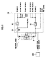
- Fig. 1 shows a schematic of an electric circuit diagram, showing a part of a power supply circuit 10 of an electric car or a hybrid car (hereinafter referred to as vehicle 20 as shown in Fig. 2 ).
- the power supply circuit connector 100 (hereinafter referred to as "service disconnecting switch 100" or “SDSW 100” for short) according to the embodiment is provided on a way of the power supply circuit 10 and serves as a main circuit switch 100A for breaking batteries from each other or connecting the batteries with each other.
- the SDSW 100 has a pair of connector housings (otherwise referred as to "first housing 1" and “second housing 2") which are attachable and detachable, and the attaching and detaching of the connector housings 1, 2 respectively disconnect and connect an intermediate potential part X-Y of a battery - to be described afterward.
- An electricity from the battery flows to an inverter INV (denoted but not shown in Fig. 1 ), a 14 V DC/DC converter (denoted but not shown in Fig. 1 ) and a 42 V DC/DC converter (denoted but not shown in Fig. 1 ) via relays R1, R2.
- the electricity from the battery is sensed with a current sensor CS and a voltage sensor (not shown in Fig. 1 ).
- the SDSW 100 also serves as a mated state sensor switch 100B for sensing a mated state of the pair of the connector housings 1, 2.
- a signal from the mated state sensor switch 100B is inputted to an ECU 200 and thereby the mated state of the connector housings 1, 2 is sensed, the ECU 200 turns on the relays R1, R2.
- the main circuit switch 100A is turned on and also the mated state sensor switch 100B is turned on, the power supply circuit 10 is brought into a conduction state.
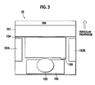
- Fig. 2 and Fig. 3 each show where the SDSW 100 is disposed.
- Fig. 2 is a side view of a part of the vehicle 20 while Fig. 3 is a plan view of a part of the vehicle 20.
- a luggage board 102 In a trunk room 107 behind a rear seat back 101 and a gasoline tank 109, a luggage board 102 is laid. Below the luggage board 102, a battery pack 104 is disposed above a tire 110 and between a right wheel house 103R and a left wheel house 103L. Behind the battery pack 104, a spare tire 105 and an auxiliary machine 106 such as an audio and the like are disposed.
- the SDSW 100 is disposed in a gap G1 between the battery pack 104 and the auxiliary machine 106.
- the SDSW 100 As described above, various components are disposed below the trunk room 107, leaving a small space. Therefore, it is preferable that the SDSW 100 is as small as possible. Moreover, the SDSW 100 is operated in a maintenance period of a power supply system or in an emergency of the vehicle 20. Therefore, the SDSW 100 should have a preferable operability even when being disposed in a place that is not preferable for operation, i.e., below the luggage board 102. Moreover, the SDSW 100 has such a structure that the connector housings 1, 2 should not be detached by a vehicular vibration and the like during travel period. To meet the above, the SDSW 100 according to the embodiment has a structure set forth below.
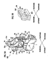
- Fig. 4A is a perspective view showing an overall structure of the SDSW 100 (main circuit mated state), according to the embodiment.
- Fig. 4B is a view of the SDSW 100 cut along the line IVB-IVB in Fig. 4A .
- Fig. 5A is a perspective view showing a state where the SDSW 100 is exploded (completely detached state).
- Fig. 5B is a perspective view of an essential part of Fig. 5A .
- front, rear, left and right are defined as shown in Fig. 4A, Fig. 4B , Fig. 5A and Fig. 5B .
- the SDSW 100 has a first housing 1 fixed to the vehicle 20 and a second housing 2 configured to be received in the first housing 1.
- a lever 3 rotatable upward and downward is fitted to the second housing 2. Rotation of the lever 3 pushes the second housing 2 into the first housing 1, allowing the second housing 2 to mate with the first housing 1 and allowing a head end part 3a of the lever 3 to mate with the first housing 1.
- the above described main circuit switch 100A and mated state sensor switch 100B are turned on.
- Each of the first housing 1, the second housing 2 and the lever 3 is made of resin.
- a cover 4 is mounted above the second housing 2. Holding a holding part 4a at a rear end part of the cover 4 and then pulling the holding part 4a rearward can remove the cover 4. With the cover 4 thus removed, replacement and the like of components received in the cover 4 are implemented.
- An upper face of the cover 4 has a step 4d, making a front upper part 4b of the cover 4 lower than a rear upper part 4c of the cover 4.
- An upper part (an upper housing 21) of the second housing 2 is so formed as to be wider than a lower part (a lower housing 22) in the right-left direction.
- a positioning protrusion 23 On each of a right sideface and a left sideface of the upper housing 21, a positioning protrusion 23, a rotary shaft 24 and a stopper 25 are disposed in such a configuration as to each protrude.
- a step part 2b is disposed on a front end face of the second housing 2.
- a locking member 26 stands on the step part 2b.
- the lever 3 has a first connector member 32 and a second connector member 33 each of which couples a pair of right and left arm plates 31, 31 with each other.
- a connector part 34 (otherwise referred to as "inserted connector part 34") is provided in such a configuration as to protrude in the direction of rotating the lever 3.
- a taper part 32a is formed on either side of the connector part 34.
- the rotary shaft 24 of the upper housing 21's sideface passes through the arm plate 31. Thereby, the lever 3 is supported in such a configuration as to rotate around the rotary shaft 24.
- a gap G2 is defined between the lever 3 and the lower housing 22. The first housing 1 is inserted into the gap G2.
- the arm plate 31 has a pair of positioning hole parts 31 a, 31b. Inserting the positioning protrusion 23 on the upper housing 21's sideface into any of the positioning hole parts 31a, 31b stops the lever 3 in a certain rotary position (completely detached position). In this case, inserting the positioning protrusion 23 into the hole part 31b allows the lever 3 to stand substantially vertically, as shown in Fig. 5A . This is defined as a completely detached state. In the completely detached state, the main circuit switch 100A and the mated state sensor switch 100B each are turned off- to be described afterward.
- Fig. 4A shows a state in the process from the completely detached state to the completely mated state. This is defined as a main circuit mated state.
- the position of the lever 3 in the main circuit mated state is defined as a main circuit mated position (otherwise referred to as "first certain position P1").
- first certain position P1 the main circuit switch 100A is turned on while the mated state sensor switch 100B is turned off - to be described afterward.
- a part of a periphery of the arm plate 31 is formed substantially into an arc (arc part 31 c) around the rotary shaft 24.
- Latch parts 31d, 31 e are formed at respective ends of the arc part 31 c.
- the latch parts 31d, 31 e caused to abut on the stopper 25 on the upper housing 21's sideface limit the lever 3's rotary range to between the completely mated position (second certain position P2) and the completely detached position.
- the first housing 1 has a receiver 11 for receiving the second housing 2.
- a connector part 12 (otherwise referred to as “receiving connector part 12") is provided in such a configuration as to correspond to the connector part 34 of the lever 3.
- a guide pin 13 (otherwise referred to as “mating-detaching mechanism” in combination with guide groove 35) protrudes on each of right and left outer sidefaces of the first housing 1.
- the receiver 11 is so formed as to correspond to a profile of the lower housing 22.
- the lower housing 22 alone is received in the receiver 11 while the upper housing 21 protrudes from the receiver 11.
- a substantially arc guide groove 35 (otherwise referred to as "mating-detaching mechanism" in combination with guide pin 13) is formed in the arm plate 31 of the lever 3.
- a guide part 35a protrudes along the guide groove 35.
- the guide part 35a is formed in a position other than a peripheral part 35b of the arm plate 35.
- Fig. 6B in combination with Fig. 5A , only from the completely detached state, the guide pin 13 can be inserted into the guide groove 35 via the peripheral part 35b apart from the guide part 35a.
- Fig. 6B shows a state where the guide pin 13 is locked to an end part of the guide groove 35, bringing about a lever temporarily locked state.
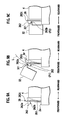
- Fig. 7A, Fig. 7B, Fig. 7C and Fig. 7D show the guide groove 35 relative to the guide pin 13 in respective states of the SDSW 100, where Fig. 7A shows the completely mated state, Fig. 7B shows the main circuit mated state, Fig. 7C shows the lever temporarily locked state, and Fig. 7D shows the completely detached state.
- Fig. 7D shows the completely detached state.
- an end part (the peripheral part 35b) of the guide groove 35 is open downward.
- the guide groove 35 is formed straightly upward by a certain distance from the peripheral part 35b.
- inserting the second housing 2 from upward into the first housing 1 engages the guide pin 13 with the guide groove 35, leading to the lever temporarily locked state shown in Fig. 7C .
- Fig. 8 is a cross sectional view of the SDSW 100 taken along the line VIII-VIII in Fig. 6A .
- an inner structure of the SDSW 100 is to be set forth.
- a fuse 29 is disposed inside the cover 4 of the second housing 2.
- a pair of thin plate terminals 27a, 27b (otherwise referred to as "first switch terminals") are connected at respective ends of the fuse 29 in the frontward-rearward direction, where a bolt 28 is used for fixing the fuse 29 to each of the first switch terminals 27a, 27b.
- first switch terminals Being bent into an alphabetical L upside down in Fig. 8 , each of the first switch terminals 27a, 27b passes through a base face of the second housing 2.
- a case part 2c protrudes from a base face of the second housing 2, covering a periphery of each of the first switch terminals 27a, 27b.
- the first switch terminals 27a, 27b each have a length that is so specified that a head end of each of the first switch terminals 27a, 27b does not protrude more downward than the case part 2c.
- a pair of thin plate terminals 14a, 14b (otherwise referred to as "main circuit terminals") pass through a base face of the first housing 1.
- a case part 1c protrudes on an inner base face of the first housing 1.
- the terminals 14a, 14b each have a length that is so specified that a head end of each of the terminals 14a,14b does not protrude more upward than the case part 1c.
- the case part 1c of the first housing 1 is received in the case part 2c of the second housing 2.
- Head end parts 14aH, 14bH of the respective main circuit terminals 14a, 14b are each bent into an alphabetical R, each forming a plate spring.
- a head end of each of the first switch terminals 27a, 27b is pushed between the respective main circuit terminals 14a,14b and the case part 1c, thus allowing the terminal 14a to contact the terminal 27a and the terminal 14b to contact the terminal 27b.
- the main circuit terminals 14a,14b can be connected with each other via the first switch terminals 27a, 27b and the fuse 29, thus turning on the main circuit switch 100A.
- the main circuit terminals 14a,14b are respectively connected with cables 18a, 18b (see Fig. 4A or Fig, 4B ).
- a bolt through hole 1d for mounting the first housing 1 to the vehicle 20 is provided on the base face of the first housing 1.
- a terminal 36 (otherwise referred to as "second switch terminal") having a cross section shaped substantially into an alphabetical U is mounted in the connector part 34 (otherwise referred to as "inserted connector part 34") of the lever 3.
- the second switch terminal 36 has a length that is so specified that the second switch terminal 36 does not protrude from an opening end face 34a below the connector part 34.
- the connector part 34 covers a periphery of the terminal 36.
- the second switch terminal 36 has a first part and a second part defining therebetween an inner width which is narrower downward in a right-and-left direction.
- a lower end part of the second switch terminal 36 is elastically deformable around an upper end part of the terminal 36 outwardly on right and left sides (see Fig. 11 ).
- an opening part 34b is defined continuously with the opening end face 34a, thus opening the lower face and rear face of the connector part 34.
- a base plate 15 is fixed in the connector part 12 (otherwise referred to as “receiving connector part 12") of the first housing 1.
- the base plate 15 extends upward and downward, with respective left and right faces thereof fitted with plate terminals 16a, 16b (otherwise referred to as “mated state sensor terminals”), as shown in Fig. 11 .
- the base plate 15 has a length that is so specified that the base plate 15 does not protrude more upward than the connector part 12. As such, the connector part 12 covers the periphery of the base plate 15.
- the mated state sensor terminals 16a, 16b are provided in the receiving connector part 12 in such a configuration as not to protrude from an opening end face 12b of the receiving connector part 12.
- An upper end part of the base plate 15 is formed into an alphabetical R Via the upper end part, the base plate 15 mates in a gap G3 between right and left extensions of the terminal 36.
- terminals 16a, 16b are connected respectively with cables 17a, 17b shown in Fig. 4B .
- a step part 12a is provided on the front face of the connector part 12 of the first housing 1.
- the step part 12a defines a space SP between the connector part 12 and the front end face of the base plate 15.
- the space SP has such a scale that, for receiving the connector part 34 in the connector part 12 by rotating the lever 3, an angled part of the connector part 34 does not interference with the connector part 12.
- the second housing 2 has the locking member 26 which is so configured as to implement the following operations: Rotation of the lever 3 is once stopped in the main circuit mated position (first certain position P1) (see Fig. 4A ), then, the lever 3 is rotated to the completely mated position (second certain position P2) (see Fig. 6A ), such that the lever 3 can be locked.
- the locking member 26 is to be set forth.
- the locking member 26 has:
- Fig. 9A, Fig. 9B and Fig. 9C each are an enlarged side view of the locking member 26 in operation, where Fig. 9B shows the main circuit mated state, and Fig. 9C shows the completely mated state.
- the nail part 262 has an upper face 262a and a lower face 262b which are formed substantially horizontal.
- the nail part 262 protrudes more frontward than the support plate 261, and protrudes more upward than the upper face of the cover 4.
- the locking member 26 is elastically deformable rearward, as depicted by a broken line.
- Fig. 9B shows the locking member 26 in the main circuit mated state in combination with the lever 3's first connector member 32 contacting the locking member 26.
- a protrusion 321 is provided corresponding to the nail part 262.
- the nail part 262 is positioned on a rotation track L of the first connector member 32.
- the protrusion 321 abuts on the upper face 262a of the nail part 262, preventing downward rotation of the lever 3.
- the upper face of the protrusion 321 of the first connector member 32 is tapered rearward. Therefore, an upper end 262c of the nail part 262 protrudes more upward than the protrusion 321, allowing a finger to push rearward the upper end 262c of the nail part 262.
- pushing rearward (rotary direction Dr) the upper end 262c elastically deforms the locking member 26 as depicted by the broken line, thus removing the nail part 262 reward out of the rotation track L of the first connector member 32. As such, nothing prevents the rotation of the lever 3, thus rotating the lever 3 more downward.
- removing the finger from the nail part 262 returns the locking member 26 to an original position by means of an elastic force, as shown in Fig. 9C .
- This state is defined as the completely mated state.
- the completely mated state the upper face of the protrusion 321 is positioned beneath the lower face 262b of the nail part 262. As such, an upward rotation of the lever 3 can be prevented, thus locking the lever 3.
- the upper end 262c of the locking member 26 is pushed rearward with the finger to thereby remove the nail part 262 rearward, thus rotating the lever 3 upward.
- FIG. 10 is a time chart showing state changes of the SDSW 100 for bringing the power supply circuit 10 into the conduction state.
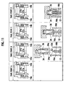
- Fig. 11 shows operations corresponding to respective time points A to D of the time chart in Fig. 10 .
- the SDSW 100 should be in the completely detached state. In the completely detached state, the main circuit switch 100A is turned off and the mated state sensor switch 100B is turned off, thus unlocking the first and second connector housings 1,2 of the SDSW 100.
- Described above is the method of bringing the SDSW 100 into the mated state after the maintenance and the like.
- a method having procedures opposite to the above described should be implemented.
- engaging an index finger and a middle finger with the taper parts 32a, 32a (see Fig. 4 ) provided on respective left and right sides at the lever 3's head end part 3a and sandwiching the connector part 34 with the index finger and middle finger can easily rotate the lever 3 upward.
- the SDSW 100 according to the above embodiment can bring about the following operations and effects.
- the nail part 262 of the locking member 26 has a cross section substantially rectangular (see Fig. 9 ).
- the locking member 26 may have such a configuration that, for example, an upper part of the nail part 262 is shaped into an alphabetical R, as shown in Fig. 12A .
- the protrusion 321 pushes the locking member 26 rearward. Therefore, it is not necessary to use the finger for pushing the upper end part of the locking member 26 rearward, thus smoothing the mating of the SDSW 100.
- the force for rotating the lever 3 is increased when the protrusion 321 rides over the nail part 262, thereby once stopping the lever 3 in the main circuit mated state.
- the increased force for rotating the lever 3 can immediately bring about the completely mated state, without once stopping the lever 3 in the main circuit mated state.
- forming a lower part of the nail part 262 into an alphabetical R can eliminate the need of pushing with the finger the locking member 26 from the completely mated state to the completely detached state, thus smoothly bringing the SDSW 100 into the detached state.
- the second switch terminal 36 moves along an arc track 36A. Then, as shown in Fig. 13 , head end parts 16aH, 16bH of the respective terminals 16a, 16b of the connector part 12 of the first housing 1 may be provided along the rotation track (arc track 36A) of the terminal 36. As such, the terminal 36 mates straightly with the head end parts 16aH, 16bH of the respective terminals 16a, 16b. Therefore, in the mating operation, the terminals 16a,16b can be prevented from being deviated from the connector part 12 and the terminal 36 can be prevented from being deviated from the connector part 34, which deviations may be caused with an excessive force applied to the terminals 16a, 16b, 36.
- the guide groove 35 is formed in the arm plate 31 of the lever 3 and the guide pin 13 is allowed to engage the guide groove 35.
- the rotation of the lever 3 allows the second housing 2 to mate with or to be detached from the first housing 1.
- the mating-detaching mechanism (including the guide pin 13 and the guide groove 35) is, however, not limited to the above structure.
- the first housing 1 includes a pair of the terminals 14a, 14b as the main circuit terminals, and a pair of the terminals 16a, 16b as the mated state sensor terminals.
- the second housing 2 includes the terminals 27a, 27b as the first switch terminals, and the terminal 36 as the second switch terminal.
- the configuration of each of the terminals 14a,14b, 16a, 16b, 27a, 27b, 36 is not limited to the above.
- the structure of the SDSW 100 is not limited to the above described as long as the following operations are implemented.
- the lever 3 is rotated to the main circuit mated position (first certain position P1) to thereby connect the main circuit terminal 14a with the first switch terminal 27a and connect the main circuit terminal 14b with the first switch terminal 27b, thus connecting the main circuit terminals 14a, 14b with each other and connecting the first switch terminals 27a, 27b with each other. Then, the lever 3 is rotated to the completely mated position (second certain position P2) to thereby connect the second switch terminal 36 with the mated state sensor terminal 16a and with the mated state sensor terminal 16b, thus connecting the mated state sensor terminals 16a, 16b with each other.
- the above operations bring the power supply circuit 10 into the conduction state.
- the locking member 26 serves as the movable member 26, such that the elastic deformation of the locking member 26 locks the lever 3.
- the structure and operation of the lock mechanism are, however, not limited to the above.
- the configuration of the connector parts that is, the receiving connector part 12 and the inserted connector part 34 having respectively the mated state sensor terminals 16a, 16b and the second switch terminal 36 is not limited to the above described.
- the present invention is not limited to the power supply circuit connector 100 according to the embodiment.
Landscapes
- Details Of Connecting Devices For Male And Female Coupling (AREA)
- Mechanical Control Devices (AREA)
- Position Input By Displaying (AREA)
- Connector Housings Or Holding Contact Members (AREA)
Abstract
Description
- The present invention relates to a power supply circuit connector for breaking or connecting a power supply circuit of a hybrid car, an electric car and the like. The present invention also relates to a method of connecting the power supply circuit.
- For operational safety of a hybrid car or an electric car, it is necessary to implement maintenance and the like in a state that a power supply circuit is manually broken (cut off).
US6982393 {family ofJapanese Patent Application Laid-Open No. 2005-142107 JP2005142107
The device ofUS6982393 has the following operations: Rotating a lever allows one connector housing to be received in another connector housing, thus connecting main circuit terminals with each other.
Moreover, sliding the one connector housing in the another connector housing connects mated state sensor terminals, thereby bringing the power supply circuit into a conduction state. - It is an object of the preset invention to provide a power supply circuit connector which allows a rotation of a lever to connect a pair of main circuit terminals with each other and to connect a pair of mated state sensor terminals with each other, keeping small-sized power supply circuit connector.
- It is another object of the present invention to provide a method of connecting the power supply circuit.
- According to a first aspect of the present invention, there is provided a power supply circuit connector of a power supply circuit, the power supply circuit connector comprising: a first housing including: a pair of main circuit terminals adapted to be connected with each other via a first switch terminal, for bringing a power supply circuit into a conduction state, and a pair of mated state sensor terminals adapted to be connected with each other, for bringing the power supply circuit into the conduction state; a second housing configured to mate with or to be detached from the first housing, the second housing including: the first switch terminal configured to connect the pair of the main circuit terminals by means of a lever rotated to a first certain position; the lever rotatably supported to the second housing, the lever including: a second switch terminal configured to make the following operation: in a state that the pair of the main circuit terminals are kept connected with each other, connecting the pair of the mated state sensor terminals with each other by means of the lever rotated to a second certain position after the first certain position; and a mating-detaching mechanism configured to make the following operations by means of the rotated lever: mating the second housing with the first housing, and detaching the second housing from the first housing.
- According to a second aspect of the present invention, there is provided a power supply circuit connector of a power supply circuit, the power supply circuit connector comprising: a housing including: a first switch terminal configured to connect a pair of main circuit terminals of another housing by means of a lever rotated to a first certain position; the lever rotatably supported to the housing, the lever including: a second switch terminal having a first part and a second part defining therebetween an inner width which is narrower downward in a right-and-left direction, a lower end part of the second switch terminal being elastically deformable around an upper end part of the second switch terminal on right and left sides; and a guide groove defined in the lever and to which a guide pin is inserted.
- According to a third aspect of the present invention, there is provided a method of connecting a power supply circuit, the method comprising: a first operation for engaging a first housing with a lever, the first housing including a pair of main circuit terminals and a pair of mated state sensor terminals while the lever being rotatably supported to a second housing; a second operation including the following sub-operations: rotating the lever to a first certain position to thereby mate the second housing with the first housing, and connecting the pair of the main circuit terminals with each other via a first switch terminal provided in the second housing; and a third operation including the following sub-operations: rotating the lever to a second certain position after the first certain position, connecting the pair of the mated state sensor terminals with each other via a second switch terminal provided in the lever, and bringing the power supply circuit into a conduction state.
- Other objects and features of the present invention will become understood from the following description with reference to the accompanying drawings.
-
-
Fig. 1 shows a schematic of an electric circuit diagram of a power supply circuit connector, an according to an embodiment of the present invention. -
Fig. 2 is a side view of a part of a vehicle, showing where the power supply circuit connector is disposed, according to the embodiment. -
Fig. 3 is a plan view of a part of the vehicle, showing where the power supply circuit connector is disposed, according to the embodiment. -
Fig. 4 is a perspective view of the power supply circuit connector in a main circuit mated state, according to the embodiment, whereFig. 4A shows an overall structure of the power supply circuit connector whileFig. 4B shows the power supply circuit connector partly cut -
Fig. 5A is a perspective view showing a state where the power supply circuit connector is exploded, i.e., completely detached state, whileFig. 5B is a perspective view of an essential part ofFig. 5A , according to the embodiment -
Fig. 6A is a perspective view of the completely mated state whileFig. 6B is a perspective view of the lever temporarily locked state. -
Fig. 7A, Fig. 7B, Fig. 7C and Fig. 7D show a guide groove relative to a guide pin in respective states of the power supply circuit connector, where -
Fig. 7A shows a completely mated state, -
Fig. 7B shows a main circuit mated state, -
Fig. 7C shows a lever temporarily locked state, and -
Fig. 7D shows a completely detached state. -
Fig. 8 a cross sectional view taken along the line VIII-VIII inFig. 6A . -
Fig. 9A, Fig. 9B and Fig. 9C each are an enlarged side view of thelocking member 26 in operation, where -
Fig. 9B shows the main circuit mated state, and -
Fig. 9C shows the completely mated state. -
Fig. 10 is a time chart showing state changes of the power supply circuit connector for bringing a power supply circuit into the conduction state. -
Fig. 11 shows operations corresponding to respective time points A to D of the time chart inFig. 10 . -
Fig. 12A and Fig. 12B show an examples of deforming a locking member. -
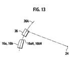
Fig. 13 shows an example of deforming the terminals. - In the following, an embodiment of the present invention will be described in detail with reference to the accompanying drawings.
- For ease of understanding, the following description will contain various directional terms, such as left, right, upper, lower, forward, rearward and the like. However, such terms are to be understood with respect to only a drawing or drawings on which the corresponding part of element is illustrated.
- Hereinafter, referring to
Fig. 1 to Fig. 13 , a powersupply circuit connector 100 is to be set forth, according to an embodiment of the present invention.
Fig. 1 shows a schematic of an electric circuit diagram, showing a part of apower supply circuit 10 of an electric car or a hybrid car (hereinafter referred to asvehicle 20 as shown inFig. 2 ). As shown inFig. 1 , the power supply circuit connector 100 (hereinafter referred to as "service disconnecting switch 100" or "SDSW 100" for short) according to the embodiment is provided on a way of thepower supply circuit 10 and serves as amain circuit switch 100A for breaking batteries from each other or connecting the batteries with each other. That is, theSDSW 100 has a pair of connector housings (otherwise referred as to "first housing 1" and "second housing 2") which are attachable and detachable, and the attaching and detaching of theconnector housings 1, 2 respectively disconnect and connect an intermediate potential part X-Y of a battery - to be described afterward.
An electricity from the battery flows to an inverter INV (denoted but not shown inFig. 1 ), a 14 V DC/DC converter (denoted but not shown inFig. 1 ) and a 42 V DC/DC converter (denoted but not shown inFig. 1 ) via relays R1, R2. The electricity from the battery is sensed with a current sensor CS and a voltage sensor (not shown inFig. 1 ). - Not only as the
main circuit switch 100A, theSDSW 100 also serves as a matedstate sensor switch 100B for sensing a mated state of the pair of theconnector housings 1, 2. When a signal from the matedstate sensor switch 100B is inputted to anECU 200 and thereby the mated state of theconnector housings 1, 2 is sensed, theECU 200 turns on the relays R1, R2.
As a result, when themain circuit switch 100A is turned on and also the matedstate sensor switch 100B is turned on, thepower supply circuit 10 is brought into a conduction state. -
Fig. 2 andFig. 3 each show where theSDSW 100 is disposed.Fig. 2 is a side view of a part of thevehicle 20 whileFig. 3 is a plan view of a part of thevehicle 20. In atrunk room 107 behind a rear seat back 101 and agasoline tank 109, aluggage board 102 is laid.
Below theluggage board 102, abattery pack 104 is disposed above atire 110 and between aright wheel house 103R and aleft wheel house 103L. Behind thebattery pack 104, aspare tire 105 and anauxiliary machine 106 such as an audio and the like are disposed. TheSDSW 100 is disposed in a gap G1 between thebattery pack 104 and theauxiliary machine 106. - As described above, various components are disposed below the
trunk room 107, leaving a small space. Therefore, it is preferable that theSDSW 100 is as small as possible. Moreover, theSDSW 100 is operated in a maintenance period of a power supply system or in an emergency of thevehicle 20. Therefore, theSDSW 100 should have a preferable operability even when being disposed in a place that is not preferable for operation, i.e., below theluggage board 102.
Moreover, theSDSW 100 has such a structure that theconnector housings 1, 2 should not be detached by a vehicular vibration and the like during travel period. To meet the above, theSDSW 100 according to the embodiment has a structure set forth below. -
Fig. 4A is a perspective view showing an overall structure of the SDSW 100 (main circuit mated state), according to the embodiment.Fig. 4B is a view of theSDSW 100 cut along the line IVB-IVB inFig. 4A .
Fig. 5A is a perspective view showing a state where theSDSW 100 is exploded (completely detached state).Fig. 5B is a perspective view of an essential part ofFig. 5A . Besides, hereinafter, for ease of explanation and for convenience sake, front, rear, left and right are defined as shown inFig. 4A, Fig. 4B ,Fig. 5A and Fig. 5B . - The
SDSW 100 has a first housing 1 fixed to thevehicle 20 and asecond housing 2 configured to be received in the first housing 1. Alever 3 rotatable upward and downward is fitted to thesecond housing 2. Rotation of thelever 3 pushes thesecond housing 2 into the first housing 1, allowing thesecond housing 2 to mate with the first housing 1 and allowing ahead end part 3a of thelever 3 to mate with the first housing 1. As such, the above describedmain circuit switch 100A and matedstate sensor switch 100B are turned on. Each of the first housing 1, thesecond housing 2 and thelever 3 is made of resin. - As shown in
Fig. 5A , acover 4 is mounted above thesecond housing 2. Holding a holdingpart 4a at a rear end part of thecover 4 and then pulling the holdingpart 4a rearward can remove thecover 4. With thecover 4 thus removed, replacement and the like of components received in thecover 4 are implemented. An upper face of thecover 4 has astep 4d, making a frontupper part 4b of thecover 4 lower than a rearupper part 4c of thecover 4. - An upper part (an upper housing 21) of the
second housing 2 is so formed as to be wider than a lower part (a lower housing 22) in the right-left direction. On each of a right sideface and a left sideface of theupper housing 21, apositioning protrusion 23, arotary shaft 24 and astopper 25 are disposed in such a configuration as to each protrude. Moreover, astep part 2b is disposed on a front end face of thesecond housing 2. A lockingmember 26 stands on thestep part 2b. - As shown in
Fig. 4A, Fig. 4B andFig. 5A , thelever 3 has afirst connector member 32 and asecond connector member 33 each of which couples a pair of right and leftarm plates first connector member 32, a connector part 34 (otherwise referred to as "insertedconnector part 34") is provided in such a configuration as to protrude in the direction of rotating thelever 3. Ataper part 32a is formed on either side of theconnector part 34. Therotary shaft 24 of theupper housing 21's sideface passes through thearm plate 31. Thereby, thelever 3 is supported in such a configuration as to rotate around therotary shaft 24. In the right-left direction, a gap G2 is defined between thelever 3 and thelower housing 22. The first housing 1 is inserted into the gap G2. - The
arm plate 31 has a pair ofpositioning hole parts positioning protrusion 23 on theupper housing 21's sideface into any of thepositioning hole parts lever 3 in a certain rotary position (completely detached position). In this case, inserting thepositioning protrusion 23 into thehole part 31b allows thelever 3 to stand substantially vertically, as shown inFig. 5A . This is defined as a completely detached state. In the completely detached state, themain circuit switch 100A and the matedstate sensor switch 100B each are turned off- to be described afterward. - As shown in
Fig. 6A (completely mated state), inserting thepositioning protrusion 23 into thehole part 31a allows an upper end face of thelever 3 to be substantially parallel to an upper face of thecover 4, thus positioning thesecond connector member 33 of thelever 3 above the frontupper part 4b of thecover 4. This is defined as a completely mated state, and the position of thelever 3 in the completely mated state is defined as a completely mated position (otherwise referred to as "second certain position P2"). In the completely mated state, theconnector part 34 of thelever 3 is positioned frontward relative to thesecond housing 2, turning on both of themain circuit switch 100A and the matedstate sensor switch 100B - to be described afterward. -
Fig. 4A (likewiseFig. 4B ) shows a state in the process from the completely detached state to the completely mated state. This is defined as a main circuit mated state. The position of thelever 3 in the main circuit mated state is defined as a main circuit mated position (otherwise referred to as "first certain position P1"). In the main circuit mated state, themain circuit switch 100A is turned on while the matedstate sensor switch 100B is turned off - to be described afterward. - As shown in
Fig. 4A and Fig. 4B , a part of a periphery of thearm plate 31 is formed substantially into an arc (arc part 31 c) around therotary shaft 24.Latch parts arc part 31 c. Thelatch parts stopper 25 on theupper housing 21's sideface limit thelever 3's rotary range to between the completely mated position (second certain position P2) and the completely detached position. - As shown in
Fig. 5A , the first housing 1 has areceiver 11 for receiving thesecond housing 2. At a front part of thereceiver 11, a connector part 12 (otherwise referred to as "receivingconnector part 12") is provided in such a configuration as to correspond to theconnector part 34 of thelever 3. A guide pin 13 (otherwise referred to as "mating-detaching mechanism" in combination with guide groove 35) protrudes on each of right and left outer sidefaces of the first housing 1. Thereceiver 11 is so formed as to correspond to a profile of thelower housing 22. Thelower housing 22 alone is received in thereceiver 11 while theupper housing 21 protrudes from thereceiver 11. - A substantially arc guide groove 35 (otherwise referred to as "mating-detaching mechanism" in combination with guide pin 13) is formed in the
arm plate 31 of thelever 3. As shown inFig. 4A (likewiseFig. 4B ), on a right-left inner face of thearm plate 31, aguide part 35a protrudes along theguide groove 35. Theguide part 35a is formed in a position other than aperipheral part 35b of thearm plate 35. As shown inFig. 6B in combination withFig. 5A , only from the completely detached state, theguide pin 13 can be inserted into theguide groove 35 via theperipheral part 35b apart from theguide part 35a. Herein,Fig. 6B shows a state where theguide pin 13 is locked to an end part of theguide groove 35, bringing about a lever temporarily locked state. -
Fig. 7A, Fig. 7B, Fig. 7C and Fig. 7D show theguide groove 35 relative to theguide pin 13 in respective states of theSDSW 100, where
Fig. 7A shows the completely mated state,
Fig. 7B shows the main circuit mated state,
Fig. 7C shows the lever temporarily locked state, and
Fig. 7D shows the completely detached state.
As shown inFig. 7D , in the completely detached state, an end part (theperipheral part 35b) of theguide groove 35 is open downward. In the completely detached state, theguide groove 35 is formed straightly upward by a certain distance from theperipheral part 35b. As such, inserting thesecond housing 2 from upward into the first housing 1 engages theguide pin 13 with theguide groove 35, leading to the lever temporarily locked state shown inFig. 7C . - In the lever temporarily locked state in
Fig. 7C , rotating thelever 3 in an arrow direction (downward and counterclockwise) inFig. 7C moves theguide groove 35 along theguide pin 13, leading to the main circuit mated state shown inFig. 7B . Theguide groove 35 is so formed that a distance R from therotary shaft 24 for thelever 3 to theguide groove 35 becomes gradually smaller from the lever temporarily locked state inFig. 7B to the main circuit mated state inFig. 7A . As such, rotation of thelever 3 works for pushing thesecond housing 2 into the first housing 1. - Then, in the main circuit mated state in
Fig. 7B , rotating thelever 3 in the arrow direction (downward and counterclockwise) moves theguide groove 35 along theguide pin 13, leading to the completely mated state shown inFig. 7A . Theguide groove 35 is so formed that the distance R from therotary shaft 24 for thelever 3 to theguide groove 35 is constant from the main circuit mated state inFig. 7B to the completely mated state inFig. 7A . As such, rotation of thelever 3 can prevent thesecond housing 2 from being pushed any further and thelever 3 alone moves, allowing theconnector part 34 of thelever 3 to mate with theconnector part 12 of the first housing 1. -
Fig. 8 is a cross sectional view of theSDSW 100 taken along the line VIII-VIII inFig. 6A . Referring toFig. 8 , an inner structure of theSDSW 100 is to be set forth. Afuse 29 is disposed inside thecover 4 of thesecond housing 2. A pair ofthin plate terminals fuse 29 in the frontward-rearward direction, where abolt 28 is used for fixing thefuse 29 to each of thefirst switch terminals Fig. 8 , each of thefirst switch terminals second housing 2. Acase part 2c protrudes from a base face of thesecond housing 2, covering a periphery of each of thefirst switch terminals first switch terminals first switch terminals case part 2c. - A pair of
thin plate terminals case part 2c of thesecond housing 2, acase part 1c protrudes on an inner base face of the first housing 1. Theterminals terminals case part 1c. Thecase part 1c of the first housing 1 is received in thecase part 2c of thesecond housing 2. - Head end parts 14aH, 14bH of the respective
main circuit terminals first switch terminals main circuit terminals case part 1c, thus allowing the terminal 14a to contact the terminal 27a and the terminal 14b to contact the terminal 27b. As such, themain circuit terminals first switch terminals fuse 29, thus turning on themain circuit switch 100A. Besides, themain circuit terminals cables Fig. 4A or Fig, 4B ). A bolt throughhole 1d for mounting the first housing 1 to thevehicle 20 is provided on the base face of the first housing 1. - As shown in
Fig. 4B , a terminal 36 (otherwise referred to as "second switch terminal") having a cross section shaped substantially into an alphabetical U is mounted in the connector part 34 (otherwise referred to as "insertedconnector part 34") of thelever 3. Thesecond switch terminal 36 has a length that is so specified that thesecond switch terminal 36 does not protrude from an openingend face 34a below theconnector part 34. As such, theconnector part 34 covers a periphery of the terminal 36. Thesecond switch terminal 36 has a first part and a second part defining therebetween an inner width which is narrower downward in a right-and-left direction. A lower end part of thesecond switch terminal 36 is elastically deformable around an upper end part of the terminal 36 outwardly on right and left sides (seeFig. 11 ). As shown inFig. 8 , on a rear face of theconnector part 34, anopening part 34b is defined continuously with the openingend face 34a, thus opening the lower face and rear face of theconnector part 34. - A
base plate 15 is fixed in the connector part 12 (otherwise referred to as "receivingconnector part 12") of the first housing 1. Thebase plate 15 extends upward and downward, with respective left and right faces thereof fitted withplate terminals Fig. 11 . Thebase plate 15 has a length that is so specified that thebase plate 15 does not protrude more upward than theconnector part 12. As such, theconnector part 12 covers the periphery of thebase plate 15. - In other words, the mated
state sensor terminals connector part 12 in such a configuration as not to protrude from an opening end face 12b of the receivingconnector part 12. - An upper end part of the
base plate 15 is formed into an alphabetical R Via the upper end part, thebase plate 15 mates in a gap G3 between right and left extensions of the terminal 36. - Besides, the
terminals cables Fig. 4B . - In
Fig. 8 , theconnector part 34 is completely received in theconnector part 12 of the first housing 1. In this state, thebase plate 15 mates in the terminal 36, allowing the terminal 36 to contact theterminals terminals state sensor switch 100B.
Besides, inFig. 8 , astep part 12a is provided on the front face of theconnector part 12 of the first housing 1. Thestep part 12a defines a space SP between theconnector part 12 and the front end face of thebase plate 15. The space SP has such a scale that, for receiving theconnector part 34 in theconnector part 12 by rotating thelever 3, an angled part of theconnector part 34 does not interference with theconnector part 12. - According to embodiment, the
second housing 2 has the lockingmember 26 which is so configured as to implement the following operations: Rotation of thelever 3 is once stopped in the main circuit mated position (first certain position P1) (seeFig. 4A ), then, thelever 3 is rotated to the completely mated position (second certain position P2) (seeFig. 6A ), such that thelever 3 can be locked.
Hereinafter, the lockingmember 26 is to be set forth. - As shown in
Fig. 5B andFig. 8 , the lockingmember 26 has: - a
support plate 261 standing on the upper face of thestep part 2b at the front end face of thesecond housing 2, and - a
nail part 262 provided at an upper end part of thesupport plate 261 and extending in right-left direction. -
Fig. 9A, Fig. 9B and Fig. 9C each are an enlarged side view of the lockingmember 26 in operation, where
Fig. 9B shows the main circuit mated state, and
Fig. 9C shows the completely mated state.
As shown inFig. 9A , thenail part 262 has anupper face 262a and alower face 262b which are formed substantially horizontal. Thenail part 262 protrudes more frontward than thesupport plate 261, and protrudes more upward than the upper face of thecover 4. Around a lower end part of thesupport plate 261, the lockingmember 26 is elastically deformable rearward, as depicted by a broken line. -
Fig. 9B shows the lockingmember 26 in the main circuit mated state in combination with thelever 3'sfirst connector member 32 contacting the lockingmember 26. On the rear end face of thefirst connector member 32, aprotrusion 321 is provided corresponding to thenail part 262. In the main circuit mated state inFig. 9B , thenail part 262 is positioned on a rotation track L of thefirst connector member 32. As such, theprotrusion 321 abuts on theupper face 262a of thenail part 262, preventing downward rotation of thelever 3. - The upper face of the
protrusion 321 of thefirst connector member 32 is tapered rearward. Therefore, anupper end 262c of thenail part 262 protrudes more upward than theprotrusion 321, allowing a finger to push rearward theupper end 262c of thenail part 262. In the main circuit mated state inFig. 9B , pushing rearward (rotary direction Dr) theupper end 262c elastically deforms the lockingmember 26 as depicted by the broken line, thus removing thenail part 262 reward out of the rotation track L of thefirst connector member 32. As such, nothing prevents the rotation of thelever 3, thus rotating thelever 3 more downward. - After the rotating of the
lever 3, removing the finger from thenail part 262 returns the lockingmember 26 to an original position by means of an elastic force, as shown inFig. 9C . This state is defined as the completely mated state. In the completely mated state, the upper face of theprotrusion 321 is positioned beneath thelower face 262b of thenail part 262. As such, an upward rotation of thelever 3 can be prevented, thus locking thelever 3.
Besides, for moving from the completely mated state to the main circuit mated state, theupper end 262c of the lockingmember 26 is pushed rearward with the finger to thereby remove thenail part 262 rearward, thus rotating thelever 3 upward. - A method of bringing the
SDSW 100 into the mated state is to be set forth.
Fig. 10 is a time chart showing state changes of theSDSW 100 for bringing thepower supply circuit 10 into the conduction state.
Fig. 11 shows operations corresponding to respective time points A to D of the time chart inFig. 10 .
For implementing maintenance and the like of the power supply system, theSDSW 100 should be in the completely detached state. In the completely detached state, themain circuit switch 100A is turned off and the matedstate sensor switch 100B is turned off, thus unlocking the first andsecond connector housings 1,2 of theSDSW 100. - In the completely detached state, inserting the first housing 1 into the
second housing 2 and thereby inserting theguide pin 13 into theguide groove 35 brings about the lever temporarily locked state (time point A). In the lever temporarily locked state, as shown inFig. 11 , thefirst switch terminals second housing 2 respectively contact themain circuit terminals main circuit switch 100A. - In the lever temporarily locked state, rotating the
lever 3 downward pushes thesecond housing 2 in the first housing 1. Then, theprotrusion 321 of thefirst connector member 32 is caused to contact thenail part 262 of the lockingmember 26, thus stopping the rotation of thelever 3, to thereby stop thelever 3 in the main circuit mated position (first certain position P1). In this state, thefirst switch terminals main circuit terminals second switch terminal 36 is kept spaced apart from the matedstate sensor terminals main circuit switch 100A and keeping the matedstate sensor switch 100B turned off (time point B). - In this state, pushing the
upper end 262c of the lockingmember 26 rearward deforms the lockingmember 26 rearward, thus removing thenail part 262 rearward from the rotation track L of theprotrusion 321. As such, thelever 3 locked by the lockingmember 26 is unlocked, thus allowing thelever 3 to be rotatable more downward. With thenail part 262 removed rearward, rotating thelever 3 downward allows the terminal 36 to contact the matedstate sensor terminals state sensor switch 100B (time point C). - Further rotating the
lever 3 downward to the completely mated position (second certain position P2) moves theprotrusion 321 more downward than thelower face 262b of thenail part 262. In this state, the elastic force returns thenail part 262 to the original position. As such, thelever 3 is locked by means of the lockingmember 26, bringing about the completely mated state (time point D). - Described above is the method of bringing the
SDSW 100 into the mated state after the maintenance and the like.
For bringing theSDSW 100 into the detached state for the maintenance and the like of the power supply system, a method having procedures opposite to the above described should be implemented. In this case, engaging an index finger and a middle finger with thetaper parts Fig. 4 ) provided on respective left and right sides at thelever 3'shead end part 3a and sandwiching theconnector part 34 with the index finger and middle finger can easily rotate thelever 3 upward. - The
SDSW 100 according to the above embodiment can bring about the following operations and effects. - (1) Rotating the
lever 3 can mate thesecond housing 2 in the first housing 1 and thereby mate theconnector part 34 of thelever 3 with theconnector part 12 of the first housing 1, thus turning on themain circuit switch 100A and the matedstate sensor switch 100B.
Therefore, theSDSW 100 can be small in size. - (2) Rotating the
lever 3 in one direction turns on or off themain circuit switch 100A and the matedstate sensor switch 100B, thus smoothing the operations of theSDSW 100 and accomplishing quick operations of theSDSW 100 in case of emergency and the like. -
- (3) Providing the locking
member 26 on the rotation track L of thelever 3 allows the lockingmember 26 to once lock (stop) the rotation of thelever 3, thus smoothly accomplishing a transfer to the main circuit mated state where only themain circuit switch 100A is turned on. - (4) Pushing the
upper end 262c of the lockingmember 26 rearward thereby removing the lockingmember 26 from the rotation track L of thelever 3 can smoothly accomplish the transfer from the main circuit mated state to the completely mated state. - (5) With the locking
member 26 locking thelever 3 to the completely mated position (second certain position P2), the connector housings (first housing 1, second housing 2) of theSDSW 100 can be prevented from being detached by means of vehicle vibration and the like during the travel period, thus stably bringing thepower supply circuit 10 into the conduction state. -
- (6) The
second switch terminal 36 is so configured as not to protrude from the openingend face 34a of the insertedconnector part 34, while the matedstate sensor terminals connector part 12. Thereby, theterminals second housing 2 from the first housing 1, thus protecting theterminals - (7) It is not necessary to slide the connector housings (first housing 1, second housing 2). Therefore, an extra receiving space in the housings is not necessary, thus preventing dust entry and the like in the
SDSW 100. - (8) The gap G3 between right and left extensions of the
second switch terminal 36 becomes narrower downward, thus narrowing down the gap G3 at an inlet of thesecond switch terminal 36, to thereby prevent the dust entry. - (9) In continuation with the opening
end face 34a of theconnector part 34, theopening part 34b is defined at the rear part of theconnector part 34, thus easily removing the dust that may have entered thesecond switch terminal 36. In the completely mated state, theopening part 34b is hidden, thus preventing dust entry through theopening part 34b. - Although the present invention has been described above by reference to the certain embodiment, the present invention is not limited to the embodiment described above. Modifications and variations of the embodiment described above will occur to those skilled in the art, in light of the above teachings.
- According to the embodiment, the
nail part 262 of the lockingmember 26 has a cross section substantially rectangular (seeFig. 9 ). However, not limited to the rectangle, the lockingmember 26 may have such a configuration that, for example, an upper part of thenail part 262 is shaped into an alphabetical R, as shown inFig. 12A . - As such, during the time for rotating the
lever 3, theprotrusion 321 pushes the lockingmember 26 rearward. Therefore, it is not necessary to use the finger for pushing the upper end part of the lockingmember 26 rearward, thus smoothing the mating of theSDSW 100. - In this case, the force for rotating the
lever 3 is increased when theprotrusion 321 rides over thenail part 262, thereby once stopping thelever 3 in the main circuit mated state. - Otherwise, the increased force for rotating the
lever 3 can immediately bring about the completely mated state, without once stopping thelever 3 in the main circuit mated state. - Contrary to the above, as shown in
Fig. 12B , forming a lower part of thenail part 262 into an alphabetical R can eliminate the need of pushing with the finger the lockingmember 26 from the completely mated state to the completely detached state, thus smoothly bringing theSDSW 100 into the detached state. - With the
lever 3 configured to rotate around therotary shaft 24, thesecond switch terminal 36 moves along anarc track 36A. Then, as shown inFig. 13 , head end parts 16aH, 16bH of therespective terminals connector part 12 of the first housing 1 may be provided along the rotation track (arc track 36A) of the terminal 36. As such, the terminal 36 mates straightly with the head end parts 16aH, 16bH of therespective terminals
Therefore, in the mating operation, theterminals connector part 12 and the terminal 36 can be prevented from being deviated from theconnector part 34, which deviations may be caused with an excessive force applied to theterminals - Besides, according to embodiment, the
guide groove 35 is formed in thearm plate 31 of thelever 3 and theguide pin 13 is allowed to engage theguide groove 35. As such, the rotation of thelever 3 allows thesecond housing 2 to mate with or to be detached from the first housing 1.
The mating-detaching mechanism (including theguide pin 13 and the guide groove 35) is, however, not limited to the above structure. - Moreover, the first housing 1 includes a pair of the
terminals terminals
Meanwhile, thesecond housing 2 includes theterminals
The configuration of each of theterminals - The structure of the
SDSW 100 is not limited to the above described as long as the following operations are implemented. - The
lever 3 is rotated to the main circuit mated position (first certain position P1) to thereby connect themain circuit terminal 14a with thefirst switch terminal 27a and connect themain circuit terminal 14b with thefirst switch terminal 27b, thus connecting themain circuit terminals first switch terminals
Then, thelever 3 is rotated to the completely mated position (second certain position P2) to thereby connect thesecond switch terminal 36 with the matedstate sensor terminal 16a and with the matedstate sensor terminal 16b, thus connecting the matedstate sensor terminals
The above operations bring thepower supply circuit 10 into the conduction state. - Moreover, the locking
member 26 serves as themovable member 26, such that the elastic deformation of the lockingmember 26 locks thelever 3. The structure and operation of the lock mechanism are, however, not limited to the above. - The configuration of the connector parts, that is, the receiving
connector part 12 and the insertedconnector part 34 having respectively the matedstate sensor terminals second switch terminal 36 is not limited to the above described. - That is, as long as the feature, function and the like of the present invention can be accomplished, the present invention is not limited to the power
supply circuit connector 100 according to the embodiment. - This application is based on a prior
Japanese Patent Application No. P2007-007737 (filed on January 17, 2007 in Japan Japanese Patent Application No. P2007-007737 - The scope of the present invention is defined with reference to the following claims.
Claims (8)
- A power supply circuit connector (100) of a power supply circuit (10), the power supply circuit connector (100) comprising:a first housing (1) including:a pair of main circuit terminals (14a, 14b) adapted to be connected with each other via a first switch terminal (27a, 27b), for bringing a power supply circuit (10) into a conduction state, anda pair of mated state sensor terminals (16a, 16b) adapted to be connected with each other, for bringing the power supply circuit (10) into the conduction state;a second housing (2) configured to mate with or to be detached from the first housing (1), the second housing (2) including:the first switch terminal (27a, 27b) configured to connect the pair of the main circuit terminals (14a, 14b) by means of a lever (3) rotated to a first certain position (P1);the lever (3) rotatably supported to the second housing (2), the lever (3) including:a second switch terminal (36) configured to make the following operation:in a state that the pair of the main circuit terminals (14a, 14b) are kept connected with each other, connecting the pair of the mated state sensor terminals (16a, 16b) with each other by means of the lever (3) rotated to a second certain position (P2) after the first certain position (P1); anda mating-detaching mechanism (13, 35) configured to make the following operations by means of the rotated lever (3):mating the second housing (2) with the first housing (1), anddetaching the second housing (2) from the first housing (1).
- The power supply circuit connector (100) according to claim 1, further comprising:a locking member (26) configured to lock the lever (3) in the second certain position (P2).
- The power supply circuit connector (100) according to claim 2, wherein
the locking member (26) includes a movable member (26) configured to make the following operations:moving from a rotation track (L) of the lever (3) to an area out of the rotation track (L), to thereby rotate the lever (3) from the first certain position (P1) to the second certain position (P2), andmoving from the area out of the rotation track (L) to the rotation track (L) of the lever (3), to thereby stop the lever (3) from rotating from the second certain position (P2) to the first certain position (P1). - The power supply circuit connector (100) according to any one of claims 1 to 3, wherein
a head end part (3a) of the lever (3) has an inserted connector part (34) having an opening end face (34a) that is open at least in a direction (Dr) of the rotated lever (3),
the second switch terminal (36) is provided in the inserted connector part (34), in such a configuration as not to protrude from the opening end face (34a) of the inserted connector part (34),
the first housing (1) has a receiving connector part (12) configured to receive the inserted connector part (34), and
the mated state sensor terminal (16a,16b) is provided in the receiving connector part (12) in such a configuration as not to protrude from an opening end face (12b) of the receiving connector part (12). - The power supply circuit connector (100) according to claim 4, wherein
on a side end face of the inserted connector part (34) on a side of a rotary shaft (24) of the lever (3), an opening part (34b) is defined continuously with the opening end face (34a) which is open. - The power supply circuit connector (100) according to any one of claims 1 to 5, wherein
at least a head end part (16aH, 16bH) of each of the mated state sensor terminals (16a, 16b) extends along a rotation track (36A) of the second switch terminal (36). - A power supply circuit connector (100) of a power supply circuit (10), the power supply circuit connector (100) comprising:a housing (2) including:a first switch terminal (27a, 27b) configured to connect a pair of main circuit terminals (14a, 14b) of another housing (1) by means of a lever (3) rotated to a first certain position (P1);the lever (3) rotatably supported to the housing (2), the lever (3) including:a second switch terminal (36) having a first part and a second part defining therebetween an inner width which is narrower downward in a right-and-left direction, a lower end part of the second switch terminal (36) being elastically deformable around an upper end part of the second switch terminal (36) on right and left sides; anda guide groove (35) defined in the lever (3) and to which a guide pin (13) is inserted.
- A method of connecting a power supply circuit (10), the method comprising:a first operation for engaging a first housing (1) with a lever (3), the first housing (1) including a pair of main circuit terminals (14a, 14b) and a pair of mated state sensor terminals (16a, 16b) while the lever (3) being rotatably supported to a second housing (2);a second operation including the following sub-operations:rotating the lever (3) to a first certain position (P1) to thereby mate the second housing (2) with the first housing (1), andconnecting the pair of the main circuit terminals (14a, 14b) with each other via a first switch terminal (27a, 27b) provided in the second housing (2); anda third operation including the following sub-operations:rotating the lever (3) to a second certain position (P2) after the first certain position (P 1),connecting the pair of the mated state sensor terminals (16a, 16b) with each other via a second switch terminal (36) provided in the lever (3), andbringing the power supply circuit (10) into a conduction state.
Applications Claiming Priority (1)
| Application Number | Priority Date | Filing Date | Title |
|---|---|---|---|
| JP2007007737A JP4875993B2 (en) | 2007-01-17 | 2007-01-17 | Power supply circuit connection device |
Publications (3)
| Publication Number | Publication Date |
|---|---|
| EP1947744A2 true EP1947744A2 (en) | 2008-07-23 |
| EP1947744A3 EP1947744A3 (en) | 2011-07-27 |
| EP1947744B1 EP1947744B1 (en) | 2013-05-01 |
Family
ID=39323582
Family Applications (1)
| Application Number | Title | Priority Date | Filing Date |
|---|---|---|---|
| EP08000377.5A Active EP1947744B1 (en) | 2007-01-17 | 2008-01-10 | Power supply circuit connector and method of connecting power supply circuit |
Country Status (4)
| Country | Link |
|---|---|
| US (1) | US7872206B2 (en) |
| EP (1) | EP1947744B1 (en) |
| JP (1) | JP4875993B2 (en) |
| CN (1) | CN101226833B (en) |
Cited By (5)
| Publication number | Priority date | Publication date | Assignee | Title |
|---|---|---|---|---|
| CN103568845A (en) * | 2012-07-25 | 2014-02-12 | 矢崎总业株式会社 | Electric connection case |
| EP2639807A4 (en) * | 2010-11-09 | 2014-05-07 | Yazaki Corp | POWER CIRCUIT INTERRUPTING DEVICE |
| DE102012216140B4 (en) * | 2011-09-12 | 2015-06-18 | Yazaki Corporation | Connector engagement body |
| CN107528157A (en) * | 2016-06-20 | 2017-12-29 | 日本航空电子工业株式会社 | Power source circuit breaker |
| IT201900004565A1 (en) * | 2019-03-27 | 2020-09-27 | Oec S R L | FUSE HOLDER. |
Families Citing this family (41)
| Publication number | Priority date | Publication date | Assignee | Title |
|---|---|---|---|---|
| JP5278180B2 (en) * | 2009-06-09 | 2013-09-04 | 日産自動車株式会社 | Power supply circuit connection device |
| DE102009053674B4 (en) * | 2009-11-19 | 2011-09-01 | Yazaki Europe Ltd. | Connector with secondary connector |
| JP5499886B2 (en) * | 2010-05-06 | 2014-05-21 | スズキ株式会社 | High voltage circuit breaker for vehicles |
| JP5569209B2 (en) * | 2010-07-21 | 2014-08-13 | 日産自動車株式会社 | Service plug mounting structure |
| JP5650971B2 (en) * | 2010-09-30 | 2015-01-07 | 矢崎総業株式会社 | Switch device |
| JP5612997B2 (en) * | 2010-10-06 | 2014-10-22 | 矢崎総業株式会社 | Power circuit breaker |
| JP2012104338A (en) * | 2010-11-09 | 2012-05-31 | Yazaki Corp | Power supply circuit breaker device |
| JP5686577B2 (en) * | 2010-11-15 | 2015-03-18 | 矢崎総業株式会社 | Connector unit |
| JP5711985B2 (en) * | 2011-01-28 | 2015-05-07 | 矢崎総業株式会社 | Power circuit breaker |
| JP5723179B2 (en) | 2011-03-04 | 2015-05-27 | 矢崎総業株式会社 | Power circuit breaker |
| CN102122594B (en) * | 2011-03-11 | 2013-05-01 | 上海诺雅克电气有限公司 | Fuse |
| JP5626136B2 (en) * | 2011-06-15 | 2014-11-19 | 住友電装株式会社 | Power circuit breaker |
| JP5840895B2 (en) * | 2011-08-22 | 2016-01-06 | 矢崎総業株式会社 | Power shut-off device |
| JP5872824B2 (en) * | 2011-09-12 | 2016-03-01 | 矢崎総業株式会社 | Power circuit breaker |
| JP5858745B2 (en) | 2011-11-21 | 2016-02-10 | 矢崎総業株式会社 | Power circuit breaker |
| DE102012006488A1 (en) * | 2012-03-29 | 2013-10-02 | GM Global Technology Operations LLC (n. d. Gesetzen des Staates Delaware) | High-voltage module with disconnector for motor vehicles |
| FR2988901B1 (en) * | 2012-04-03 | 2015-01-30 | Renault Sa | DEVICE FOR ELECTRICAL SAFETY CUT |
| EP2680374B1 (en) * | 2012-06-29 | 2020-01-22 | Aptiv Technologies Limited | Connection device |
| JP2014011124A (en) * | 2012-07-03 | 2014-01-20 | Nissan Motor Co Ltd | Lever type connector |
| US9251985B2 (en) * | 2013-08-08 | 2016-02-02 | Lg Chem, Ltd. | Fuse lock-out assembly for a battery pack |
| JP6099203B2 (en) * | 2013-09-03 | 2017-03-22 | 日本航空電子工業株式会社 | Connector device |
| US9847610B2 (en) * | 2014-01-16 | 2017-12-19 | Ford Global Technologies, Llc | Electric vehicle service disconnect position indicator |
| JP6309804B2 (en) * | 2014-03-28 | 2018-04-11 | 矢崎総業株式会社 | Lever fitting type connector |
| US9853275B2 (en) | 2014-04-04 | 2017-12-26 | Ford Global Technologies, Llc | Battery pack array separator |
| JP6377425B2 (en) * | 2014-06-20 | 2018-08-22 | 矢崎総業株式会社 | Power circuit breaker |
| US9397459B2 (en) * | 2014-08-15 | 2016-07-19 | Lear Corporation | Manual service disconnect with screw cover |
| JP6182515B2 (en) * | 2014-08-19 | 2017-08-16 | 日本航空電子工業株式会社 | Connector device |
| JP6492527B2 (en) * | 2014-10-23 | 2019-04-03 | 三菱自動車工業株式会社 | Arrangement structure of canister and auxiliary battery in vehicle |
| JP6200933B2 (en) * | 2015-11-10 | 2017-09-20 | タイコエレクトロニクスジャパン合同会社 | Lever type connector assembly |
| JP6663790B2 (en) * | 2016-05-12 | 2020-03-13 | 日本航空電子工業株式会社 | Connector device |
| JP6692718B2 (en) * | 2016-08-16 | 2020-05-13 | 日本航空電子工業株式会社 | Connector device |
| JP6720061B2 (en) * | 2016-11-18 | 2020-07-08 | 日本航空電子工業株式会社 | Connector device |
| JP6792424B2 (en) * | 2016-11-18 | 2020-11-25 | 日本航空電子工業株式会社 | Connector device |
| JP6581958B2 (en) * | 2016-12-09 | 2019-09-25 | 矢崎総業株式会社 | Voltage detection structure and voltage detection module |
| JP6592475B2 (en) * | 2017-04-27 | 2019-10-16 | 矢崎総業株式会社 | Lever fitting type connector |
| JP6793684B2 (en) * | 2018-06-19 | 2020-12-02 | 矢崎総業株式会社 | Power circuit breaker |
| KR102887127B1 (en) * | 2020-11-10 | 2025-11-14 | 주식회사 엘지에너지솔루션 | Switch-type power disconnection device and Battery pack including the same |
| US11923642B2 (en) * | 2021-02-10 | 2024-03-05 | Juniper Networks, Inc. | Apparatus, system, and method for protecting power connectors against high-power arcing |
| EP4052968B1 (en) | 2021-03-01 | 2025-11-12 | Aptiv Technologies AG | High voltage power distributor |
| CN119787030A (en) * | 2021-12-03 | 2025-04-08 | 富士康(昆山)电脑接插件有限公司 | Electrical connector assembly |
| JP7764283B2 (en) | 2022-03-07 | 2025-11-05 | 日本航空電子工業株式会社 | Connector Assembly |
Citations (1)
| Publication number | Priority date | Publication date | Assignee | Title |
|---|---|---|---|---|
| JP2005142107A (en) | 2003-11-10 | 2005-06-02 | Yazaki Corp | Lever fitting type power circuit breaker |
Family Cites Families (9)
| Publication number | Priority date | Publication date | Assignee | Title |
|---|---|---|---|---|
| US6361356B1 (en) * | 2000-10-03 | 2002-03-26 | Delphi Technologies, Inc. | Electrical connector position assurance device |
| JP2002319338A (en) * | 2001-04-23 | 2002-10-31 | Auto Network Gijutsu Kenkyusho:Kk | Breaker device |
| JP3820354B2 (en) | 2001-05-16 | 2006-09-13 | 矢崎総業株式会社 | Lever fitting type power circuit breaker |
| JP3798280B2 (en) | 2001-09-25 | 2006-07-19 | 矢崎総業株式会社 | Lever fitting type power circuit breaker |
| JP2003100382A (en) | 2001-09-25 | 2003-04-04 | Yazaki Corp | Lever fitting type power supply circuit breaker |
| US6580045B1 (en) * | 2002-06-03 | 2003-06-17 | Excel Cell Electronic Co., Ltd. | Switch with pivotable actuator |
| TW553540U (en) * | 2002-12-13 | 2003-09-11 | Hon Hai Prec Ind Co Ltd | Electrical connector assembly |
| JP4257832B2 (en) * | 2003-04-03 | 2009-04-22 | アルプス電気株式会社 | Switch device |
| JP4678333B2 (en) * | 2005-09-29 | 2011-04-27 | 住友電装株式会社 | Lever type connector |
-
2007
- 2007-01-17 JP JP2007007737A patent/JP4875993B2/en active Active
-
2008
- 2008-01-03 CN CN2008100019337A patent/CN101226833B/en active Active
- 2008-01-10 EP EP08000377.5A patent/EP1947744B1/en active Active
- 2008-01-14 US US12/013,852 patent/US7872206B2/en active Active
Patent Citations (2)
| Publication number | Priority date | Publication date | Assignee | Title |
|---|---|---|---|---|
| JP2005142107A (en) | 2003-11-10 | 2005-06-02 | Yazaki Corp | Lever fitting type power circuit breaker |
| US6982393B2 (en) | 2003-11-10 | 2006-01-03 | Yazaki Corporation | Lever fitting-type power supply circuit breaker |
Cited By (7)
| Publication number | Priority date | Publication date | Assignee | Title |
|---|---|---|---|---|
| EP2639807A4 (en) * | 2010-11-09 | 2014-05-07 | Yazaki Corp | POWER CIRCUIT INTERRUPTING DEVICE |
| US8986024B2 (en) | 2010-11-09 | 2015-03-24 | Yazaki Corporation | Power supply circuit disconnection device |
| DE102012216140B4 (en) * | 2011-09-12 | 2015-06-18 | Yazaki Corporation | Connector engagement body |
| CN103568845A (en) * | 2012-07-25 | 2014-02-12 | 矢崎总业株式会社 | Electric connection case |
| CN107528157A (en) * | 2016-06-20 | 2017-12-29 | 日本航空电子工业株式会社 | Power source circuit breaker |
| US10163590B2 (en) | 2016-06-20 | 2018-12-25 | Japan Aviation Electronics Industry, Limited | Power-circuit breaking device |
| IT201900004565A1 (en) * | 2019-03-27 | 2020-09-27 | Oec S R L | FUSE HOLDER. |
Also Published As
| Publication number | Publication date |
|---|---|
| JP2008176969A (en) | 2008-07-31 |
| US7872206B2 (en) | 2011-01-18 |
| US20080185276A1 (en) | 2008-08-07 |
| CN101226833A (en) | 2008-07-23 |
| JP4875993B2 (en) | 2012-02-15 |
| EP1947744A3 (en) | 2011-07-27 |
| EP1947744B1 (en) | 2013-05-01 |
| CN101226833B (en) | 2011-12-07 |
Similar Documents
| Publication | Publication Date | Title |
|---|---|---|
| EP1947744B1 (en) | Power supply circuit connector and method of connecting power supply circuit | |
| CN108454764B (en) | Mounting member for bicycle battery unit, battery unit assembly, and coupling member | |
| US9004935B2 (en) | Safety plug device for high-voltage battery | |
| US20140364010A1 (en) | Connector device | |
| JP2005237196A (en) | Junction box and its assembly method | |
| WO2012063549A1 (en) | Power source circuit cutoff device | |
| CN103764437B (en) | Blocking device | |
| JPWO2019073855A1 (en) | Port lock actuator device for vehicle inlet | |
| US8373390B2 (en) | Safety device for cutting-off high voltage for hybrid electric vehicle | |
| JP2000311576A (en) | Power cut-off device | |
| US12476426B2 (en) | Terminal block | |
| US8022320B2 (en) | Lever engagement type electric power source circuit breaker | |
| JPWO2019073851A1 (en) | Port lock actuator device for vehicle inlet | |
| US20220052495A1 (en) | Handle switch device | |
| JP3960259B2 (en) | Connector connection structure | |
| US6572401B2 (en) | Connector locking member with disengagement feature | |
| JP7368437B2 (en) | connector | |
| JP2025032563A (en) | Electrical connection structure | |
| CN211442574U (en) | Lock assembly for shared bicycle and shared bicycle | |
| JP3906646B2 (en) | Electrical junction box | |
| EP3960970B1 (en) | Locking device | |
| JP7368436B2 (en) | connector | |
| JP2014011124A (en) | Lever type connector | |
| US12573707B2 (en) | Electrical apparatus | |
| US20260081408A1 (en) | Protective cover assembly structure and electrical junction box |
Legal Events
| Date | Code | Title | Description |
|---|---|---|---|
| PUAI | Public reference made under article 153(3) epc to a published international application that has entered the european phase |
Free format text: ORIGINAL CODE: 0009012 |
|
| 17P | Request for examination filed |
Effective date: 20080110 |
|
| AK | Designated contracting states |
Kind code of ref document: A2 Designated state(s): AT BE BG CH CY CZ DE DK EE ES FI FR GB GR HR HU IE IS IT LI LT LU LV MC MT NL NO PL PT RO SE SI SK TR |
|
| AX | Request for extension of the european patent |
Extension state: AL BA MK RS |
|
| REG | Reference to a national code |
Ref country code: DE Ref legal event code: R079 Ref document number: 602008024195 Country of ref document: DE Free format text: PREVIOUS MAIN CLASS: H01R0013629000 Ipc: H01R0013700000 |
|
| PUAL | Search report despatched |
Free format text: ORIGINAL CODE: 0009013 |
|
| AK | Designated contracting states |
Kind code of ref document: A3 Designated state(s): AT BE BG CH CY CZ DE DK EE ES FI FR GB GR HR HU IE IS IT LI LT LU LV MC MT NL NO PL PT RO SE SI SK TR |
|
| AX | Request for extension of the european patent |
Extension state: AL BA MK RS |
|
| RIC1 | Information provided on ipc code assigned before grant |
Ipc: H01H 85/54 20060101ALI20110621BHEP Ipc: H01R 13/629 20060101ALI20110621BHEP Ipc: H01R 13/70 20060101AFI20110621BHEP |
|
| AKX | Designation fees paid |
Designated state(s): DE FR GB |
|
| 17Q | First examination report despatched |
Effective date: 20120524 |
|
| GRAP | Despatch of communication of intention to grant a patent |
Free format text: ORIGINAL CODE: EPIDOSNIGR1 |
|
| GRAS | Grant fee paid |
Free format text: ORIGINAL CODE: EPIDOSNIGR3 |
|
| GRAA | (expected) grant |
Free format text: ORIGINAL CODE: 0009210 |
|
| AK | Designated contracting states |
Kind code of ref document: B1 Designated state(s): DE FR GB |
|
| REG | Reference to a national code |
Ref country code: GB Ref legal event code: FG4D |
|
| REG | Reference to a national code |
Ref country code: DE Ref legal event code: R082 Ref document number: 602008024195 Country of ref document: DE Representative=s name: GRUENECKER, KINKELDEY, STOCKMAIR & SCHWANHAEUS, DE Ref country code: DE Ref legal event code: R082 Ref document number: 602008024195 Country of ref document: DE Representative=s name: GRUENECKER PATENT- UND RECHTSANWAELTE PARTG MB, DE |
|
| REG | Reference to a national code |
Ref country code: DE Ref legal event code: R096 Ref document number: 602008024195 Country of ref document: DE Effective date: 20130627 |
|
| PLBE | No opposition filed within time limit |
Free format text: ORIGINAL CODE: 0009261 |
|
| STAA | Information on the status of an ep patent application or granted ep patent |
Free format text: STATUS: NO OPPOSITION FILED WITHIN TIME LIMIT |
|
| 26N | No opposition filed |
Effective date: 20140204 |
|
| REG | Reference to a national code |
Ref country code: DE Ref legal event code: R097 Ref document number: 602008024195 Country of ref document: DE Effective date: 20140204 |
|
| REG | Reference to a national code |
Ref country code: FR Ref legal event code: PLFP Year of fee payment: 9 |
|
| REG | Reference to a national code |
Ref country code: FR Ref legal event code: PLFP Year of fee payment: 10 |
|
| REG | Reference to a national code |
Ref country code: FR Ref legal event code: PLFP Year of fee payment: 11 |
|
| PGFP | Annual fee paid to national office [announced via postgrant information from national office to epo] |
Ref country code: GB Payment date: 20251220 Year of fee payment: 19 |
|
| PGFP | Annual fee paid to national office [announced via postgrant information from national office to epo] |
Ref country code: FR Payment date: 20251218 Year of fee payment: 19 |
|
| PGFP | Annual fee paid to national office [announced via postgrant information from national office to epo] |
Ref country code: DE Payment date: 20251217 Year of fee payment: 19 |