JP6720061B2 - Connector device - Google Patents

Connector device Download PDF

Info

Publication number
JP6720061B2
JP6720061B2 JP2016225517A JP2016225517A JP6720061B2 JP 6720061 B2 JP6720061 B2 JP 6720061B2 JP 2016225517 A JP2016225517 A JP 2016225517A JP 2016225517 A JP2016225517 A JP 2016225517A JP 6720061 B2 JP6720061 B2 JP 6720061B2
Authority
JP
Japan
Prior art keywords
connector
state
mating
housing
power supply
Prior art date
Legal status (The legal status is an assumption and is not a legal conclusion. Google has not performed a legal analysis and makes no representation as to the accuracy of the status listed.)
Active
Application number
JP2016225517A
Other languages
Japanese (ja)
Other versions
JP2018081894A5 (en
JP2018081894A (en
Inventor
勇也 田端
勇也 田端
Current Assignee (The listed assignees may be inaccurate. Google has not performed a legal analysis and makes no representation or warranty as to the accuracy of the list.)
Japan Aviation Electronics Industry Ltd
Original Assignee
Japan Aviation Electronics Industry Ltd
Priority date (The priority date is an assumption and is not a legal conclusion. Google has not performed a legal analysis and makes no representation as to the accuracy of the date listed.)
Filing date
Publication date
Application filed by Japan Aviation Electronics Industry Ltd filed Critical Japan Aviation Electronics Industry Ltd
Priority to JP2016225517A priority Critical patent/JP6720061B2/en
Priority to US15/722,571 priority patent/US10008805B2/en
Priority to KR1020170129289A priority patent/KR101887079B1/en
Priority to CN201710949659.5A priority patent/CN108075308B/en
Publication of JP2018081894A publication Critical patent/JP2018081894A/en
Publication of JP2018081894A5 publication Critical patent/JP2018081894A5/ja
Application granted granted Critical
Publication of JP6720061B2 publication Critical patent/JP6720061B2/en
Active legal-status Critical Current
Anticipated expiration legal-status Critical

Links

Images

Classifications

    • HELECTRICITY
    • H01ELECTRIC ELEMENTS
    • H01RELECTRICALLY-CONDUCTIVE CONNECTIONS; STRUCTURAL ASSOCIATIONS OF A PLURALITY OF MUTUALLY-INSULATED ELECTRICAL CONNECTING ELEMENTS; COUPLING DEVICES; CURRENT COLLECTORS
    • H01R13/00Details of coupling devices of the kinds covered by groups H01R12/70 or H01R24/00 - H01R33/00
    • H01R13/62Means for facilitating engagement or disengagement of coupling parts or for holding them in engagement
    • H01R13/629Additional means for facilitating engagement or disengagement of coupling parts, e.g. aligning or guiding means, levers, gas pressure electrical locking indicators, manufacturing tolerances
    • H01R13/633Additional means for facilitating engagement or disengagement of coupling parts, e.g. aligning or guiding means, levers, gas pressure electrical locking indicators, manufacturing tolerances for disengagement only
    • HELECTRICITY
    • H01ELECTRIC ELEMENTS
    • H01RELECTRICALLY-CONDUCTIVE CONNECTIONS; STRUCTURAL ASSOCIATIONS OF A PLURALITY OF MUTUALLY-INSULATED ELECTRICAL CONNECTING ELEMENTS; COUPLING DEVICES; CURRENT COLLECTORS
    • H01R13/00Details of coupling devices of the kinds covered by groups H01R12/70 or H01R24/00 - H01R33/00
    • H01R13/66Structural association with built-in electrical component
    • H01R13/70Structural association with built-in electrical component with built-in switch
    • H01R13/703Structural association with built-in electrical component with built-in switch operated by engagement or disengagement of coupling parts, e.g. dual-continuity coupling part
    • H01R13/7036Structural association with built-in electrical component with built-in switch operated by engagement or disengagement of coupling parts, e.g. dual-continuity coupling part the switch being in series with coupling part, e.g. dead coupling, explosion proof coupling
    • HELECTRICITY
    • H01ELECTRIC ELEMENTS
    • H01RELECTRICALLY-CONDUCTIVE CONNECTIONS; STRUCTURAL ASSOCIATIONS OF A PLURALITY OF MUTUALLY-INSULATED ELECTRICAL CONNECTING ELEMENTS; COUPLING DEVICES; CURRENT COLLECTORS
    • H01R13/00Details of coupling devices of the kinds covered by groups H01R12/70 or H01R24/00 - H01R33/00
    • H01R13/62Means for facilitating engagement or disengagement of coupling parts or for holding them in engagement
    • H01R13/629Additional means for facilitating engagement or disengagement of coupling parts, e.g. aligning or guiding means, levers, gas pressure electrical locking indicators, manufacturing tolerances
    • H01R13/62933Comprising exclusively pivoting lever
    • H01R13/62938Pivoting lever comprising own camming means
    • BPERFORMING OPERATIONS; TRANSPORTING
    • B60VEHICLES IN GENERAL
    • B60LPROPULSION OF ELECTRICALLY-PROPELLED VEHICLES; SUPPLYING ELECTRIC POWER FOR AUXILIARY EQUIPMENT OF ELECTRICALLY-PROPELLED VEHICLES; ELECTRODYNAMIC BRAKE SYSTEMS FOR VEHICLES IN GENERAL; MAGNETIC SUSPENSION OR LEVITATION FOR VEHICLES; MONITORING OPERATING VARIABLES OF ELECTRICALLY-PROPELLED VEHICLES; ELECTRIC SAFETY DEVICES FOR ELECTRICALLY-PROPELLED VEHICLES
    • B60L53/00Methods of charging batteries, specially adapted for electric vehicles; Charging stations or on-board charging equipment therefor; Exchange of energy storage elements in electric vehicles
    • B60L53/10Methods of charging batteries, specially adapted for electric vehicles; Charging stations or on-board charging equipment therefor; Exchange of energy storage elements in electric vehicles characterised by the energy transfer between the charging station and the vehicle
    • B60L53/14Conductive energy transfer
    • HELECTRICITY
    • H01ELECTRIC ELEMENTS
    • H01RELECTRICALLY-CONDUCTIVE CONNECTIONS; STRUCTURAL ASSOCIATIONS OF A PLURALITY OF MUTUALLY-INSULATED ELECTRICAL CONNECTING ELEMENTS; COUPLING DEVICES; CURRENT COLLECTORS
    • H01R13/00Details of coupling devices of the kinds covered by groups H01R12/70 or H01R24/00 - H01R33/00
    • H01R13/46Bases; Cases
    • H01R13/502Bases; Cases composed of different pieces
    • HELECTRICITY
    • H01ELECTRIC ELEMENTS
    • H01RELECTRICALLY-CONDUCTIVE CONNECTIONS; STRUCTURAL ASSOCIATIONS OF A PLURALITY OF MUTUALLY-INSULATED ELECTRICAL CONNECTING ELEMENTS; COUPLING DEVICES; CURRENT COLLECTORS
    • H01R13/00Details of coupling devices of the kinds covered by groups H01R12/70 or H01R24/00 - H01R33/00
    • H01R13/648Protective earth or shield arrangements on coupling devices, e.g. anti-static shielding  
    • H01R13/658High frequency shielding arrangements, e.g. against EMI [Electro-Magnetic Interference] or EMP [Electro-Magnetic Pulse]
    • HELECTRICITY
    • H01ELECTRIC ELEMENTS
    • H01RELECTRICALLY-CONDUCTIVE CONNECTIONS; STRUCTURAL ASSOCIATIONS OF A PLURALITY OF MUTUALLY-INSULATED ELECTRICAL CONNECTING ELEMENTS; COUPLING DEVICES; CURRENT COLLECTORS
    • H01R24/00Two-part coupling devices, or either of their cooperating parts, characterised by their overall structure
    • H01R24/005Two-part coupling devices, or either of their cooperating parts, characterised by their overall structure requiring successive relative motions to complete the coupling, e.g. bayonet type
    • BPERFORMING OPERATIONS; TRANSPORTING
    • B60VEHICLES IN GENERAL
    • B60YINDEXING SCHEME RELATING TO ASPECTS CROSS-CUTTING VEHICLE TECHNOLOGY
    • B60Y2200/00Type of vehicle
    • B60Y2200/90Vehicles comprising electric prime movers
    • B60Y2200/91Electric vehicles
    • BPERFORMING OPERATIONS; TRANSPORTING
    • B60VEHICLES IN GENERAL
    • B60YINDEXING SCHEME RELATING TO ASPECTS CROSS-CUTTING VEHICLE TECHNOLOGY
    • B60Y2200/00Type of vehicle
    • B60Y2200/90Vehicles comprising electric prime movers
    • B60Y2200/92Hybrid vehicles
    • HELECTRICITY
    • H01ELECTRIC ELEMENTS
    • H01RELECTRICALLY-CONDUCTIVE CONNECTIONS; STRUCTURAL ASSOCIATIONS OF A PLURALITY OF MUTUALLY-INSULATED ELECTRICAL CONNECTING ELEMENTS; COUPLING DEVICES; CURRENT COLLECTORS
    • H01R2201/00Connectors or connections adapted for particular applications
    • H01R2201/26Connectors or connections adapted for particular applications for vehicles
    • YGENERAL TAGGING OF NEW TECHNOLOGICAL DEVELOPMENTS; GENERAL TAGGING OF CROSS-SECTIONAL TECHNOLOGIES SPANNING OVER SEVERAL SECTIONS OF THE IPC; TECHNICAL SUBJECTS COVERED BY FORMER USPC CROSS-REFERENCE ART COLLECTIONS [XRACs] AND DIGESTS
    • Y02TECHNOLOGIES OR APPLICATIONS FOR MITIGATION OR ADAPTATION AGAINST CLIMATE CHANGE
    • Y02TCLIMATE CHANGE MITIGATION TECHNOLOGIES RELATED TO TRANSPORTATION
    • Y02T10/00Road transport of goods or passengers
    • Y02T10/60Other road transportation technologies with climate change mitigation effect
    • Y02T10/70Energy storage systems for electromobility, e.g. batteries
    • YGENERAL TAGGING OF NEW TECHNOLOGICAL DEVELOPMENTS; GENERAL TAGGING OF CROSS-SECTIONAL TECHNOLOGIES SPANNING OVER SEVERAL SECTIONS OF THE IPC; TECHNICAL SUBJECTS COVERED BY FORMER USPC CROSS-REFERENCE ART COLLECTIONS [XRACs] AND DIGESTS
    • Y02TECHNOLOGIES OR APPLICATIONS FOR MITIGATION OR ADAPTATION AGAINST CLIMATE CHANGE
    • Y02TCLIMATE CHANGE MITIGATION TECHNOLOGIES RELATED TO TRANSPORTATION
    • Y02T10/00Road transport of goods or passengers
    • Y02T10/60Other road transportation technologies with climate change mitigation effect
    • Y02T10/7072Electromobility specific charging systems or methods for batteries, ultracapacitors, supercapacitors or double-layer capacitors
    • YGENERAL TAGGING OF NEW TECHNOLOGICAL DEVELOPMENTS; GENERAL TAGGING OF CROSS-SECTIONAL TECHNOLOGIES SPANNING OVER SEVERAL SECTIONS OF THE IPC; TECHNICAL SUBJECTS COVERED BY FORMER USPC CROSS-REFERENCE ART COLLECTIONS [XRACs] AND DIGESTS
    • Y02TECHNOLOGIES OR APPLICATIONS FOR MITIGATION OR ADAPTATION AGAINST CLIMATE CHANGE
    • Y02TCLIMATE CHANGE MITIGATION TECHNOLOGIES RELATED TO TRANSPORTATION
    • Y02T90/00Enabling technologies or technologies with a potential or indirect contribution to GHG emissions mitigation
    • Y02T90/10Technologies relating to charging of electric vehicles
    • Y02T90/12Electric charging stations
    • YGENERAL TAGGING OF NEW TECHNOLOGICAL DEVELOPMENTS; GENERAL TAGGING OF CROSS-SECTIONAL TECHNOLOGIES SPANNING OVER SEVERAL SECTIONS OF THE IPC; TECHNICAL SUBJECTS COVERED BY FORMER USPC CROSS-REFERENCE ART COLLECTIONS [XRACs] AND DIGESTS
    • Y02TECHNOLOGIES OR APPLICATIONS FOR MITIGATION OR ADAPTATION AGAINST CLIMATE CHANGE
    • Y02TCLIMATE CHANGE MITIGATION TECHNOLOGIES RELATED TO TRANSPORTATION
    • Y02T90/00Enabling technologies or technologies with a potential or indirect contribution to GHG emissions mitigation
    • Y02T90/10Technologies relating to charging of electric vehicles
    • Y02T90/14Plug-in electric vehicles

Landscapes

  • Engineering & Computer Science (AREA)
  • Power Engineering (AREA)
  • Transportation (AREA)
  • Mechanical Engineering (AREA)
  • Details Of Connecting Devices For Male And Female Coupling (AREA)

Description

本発明は、例えば電気自動車やハイブリッドカーに取り付けられて、電源システムから供給される電力を中継するコネクタ装置に関する。 The present invention relates to a connector device mounted on, for example, an electric vehicle or a hybrid car to relay electric power supplied from a power supply system.

このタイプのコネクタ装置は、100アンペア程度の大電流を中継するために使用されることがある。従って、メンテナンス作業を行う作業者の安全を考慮した機構を備える必要がある。このタイプのコネクタ装置は、例えば、特許文献1に開示されている。 This type of connector device may be used to relay large currents on the order of 100 amps. Therefore, it is necessary to provide a mechanism in consideration of the safety of workers who perform maintenance work. This type of connector device is disclosed in Patent Document 1, for example.

図41に示されるように、特許文献1に開示されたレバー嵌合式電源回路遮断装置(コネクタ装置)800は、一方のコネクタ900と、他方のコネクタ950と、レバー910とを備えている。レバー910は、一方のコネクタ900に操作可能に支持されている。このレバー910にはカム溝912が設けられており、他方のコネクタ950にはカムピン952が設けられている。カムピン952は、カム溝912に挿入されている。一方のコネクタ900には、電源回路の一部を構成する雄端子(電源端子)が設けられている(図示せず)。レバー910には、嵌合検知雄端子(検知端子)が設けられている(図示せず)。他方のコネクタ950には、電源回路の一部を構成する雌端子(電源端子)と嵌合検知雌端子(検知端子)とが設けられている(図示せず)。 As shown in FIG. 41, the lever-fitting type power circuit breaker (connector device) 800 disclosed in Patent Document 1 includes one connector 900, the other connector 950, and a lever 910. The lever 910 is operably supported by the one connector 900. The lever 910 is provided with a cam groove 912, and the other connector 950 is provided with a cam pin 952. The cam pin 952 is inserted in the cam groove 912. One connector 900 is provided with a male terminal (power supply terminal) forming a part of the power supply circuit (not shown). The lever 910 is provided with a fitting detection male terminal (detection terminal) (not shown). The other connector 950 is provided with a female terminal (power supply terminal) and a fitting detection female terminal (detection terminal) that form part of the power supply circuit (not shown).

図41(a)及び図41(b)から理解されるように、レバー910を押し下げると、一方のコネクタ900が下方に移動し、雄端子と雌端子とが接続される。これにより、電源回路が形成される。図41(b)及び図41(c)から理解されるように、レバー910を水平にスライドさせると、嵌合検知雄端子と嵌合検知雌端子が接続され、これによって電源回路が通電状態となる。一方のコネクタ900を他方のコネクタ950から外す際には、上述した操作が逆の順番で行われる。具体的には、まず、レバー910を接続時の方向と逆方向にスライドさせ、嵌合検知雄端子と嵌合検知雌端子との接続を解除する。次に、レバー910を持ちあげて、雄端子と雄端子との接続を解除する。 As understood from FIGS. 41(a) and 41(b), when the lever 910 is pushed down, one connector 900 moves downward, and the male terminal and the female terminal are connected. As a result, the power supply circuit is formed. As understood from FIGS. 41(b) and 41(c), when the lever 910 is slid horizontally, the fitting detection male terminal and the fitting detection female terminal are connected to each other, whereby the power supply circuit is turned on. Become. When detaching one connector 900 from the other connector 950, the above-described operations are performed in the reverse order. Specifically, first, the lever 910 is slid in the direction opposite to the connecting direction to release the connection between the fitting detection male terminal and the fitting detection female terminal. Next, the lever 910 is lifted to disconnect the male terminals from each other.

特開2002−343169号公報JP 2002-343169 A

作業者の感電防止のためには、嵌合検知雄端子と嵌合検知雌端子との接続が解除されてから、雄端子と雌端子の接続が解除されるまでの間に、通電が確実に停止されるのに十分な時間が経過している必要がある。即ち、検知端子の接続解除と電源端子の接続解除との間に一定の時間差が必要である。 To prevent electric shock to the operator, make sure that the power is supplied between the disconnection of the male and female terminals for mating detection and the disconnection of the male and female terminals. It must be long enough to be stopped. That is, a certain time difference is required between disconnection of the detection terminal and disconnection of the power supply terminal.

しかしながら、特許文献1のコネクタ装置においては、レバーのスライド動作とレバーの持ち上げ動作とを連続的に行うことが可能である。そのため、特許文献1のコネクタ装置においては、検知端子の接続解除と電源端子の接続解除が、殆ど時間差なく行われる恐れがある。 However, in the connector device of Patent Document 1, it is possible to continuously perform the sliding operation of the lever and the lifting operation of the lever. Therefore, in the connector device of Patent Document 1, the disconnection of the detection terminal and the disconnection of the power supply terminal may be performed with almost no time lag.

そこで、本発明は、検知端子の接続解除と電源端子の接続解除との間に十分な時間差を確実に得ることができるコネクタ装置を提供することを目的とする。 Therefore, an object of the present invention is to provide a connector device that can reliably obtain a sufficient time difference between disconnection of a detection terminal and disconnection of a power supply terminal.

本発明は、第1のコネクタ装置として、
コネクタと、前記コネクタと嵌合可能な相手側コネクタとを備えるコネクタ装置であって、
前記コネクタは、ハウジングと、電源端子と、検知端子とを備えており、
前記電源端子及び前記検知端子は、前記ハウジングに保持されており、
前記ハウジングには、第1被規制部及び第2被規制部が設けられており、
前記相手側コネクタは、相手側ハウジングと、相手側電源端子と、相手側検知端子とを備えており、
前記相手側電源端子及び前記相手側検知端子は、前記相手側ハウジングに保持されており、
前記相手側ハウジングには、第1規制部及び第2規制部が設けられており、
前記ハウジング又は前記相手側ハウジングには、第1解除部が設けられており、
前記ハウジング又は前記相手側ハウジングには、第2解除部が設けられており、
前記ハウジング又は前記相手側ハウジングには、阻止部が設けられており、
前記コネクタは、前記相手側コネクタに対して、第1状態、第2状態及び第3状態の3状態をとりうるものであり、
前記コネクタが前記第1状態にあるとき、前記電源端子及び前記検知端子は、前記相手側電源端子及び前記相手側検知端子に夫々接続されており、
前記コネクタが前記第2状態にあるとき、前記電源端子は前記相手側電源端子に接続されている一方、前記検知端子は前記相手側検知端子に接続されておらず、
前記コネクタが前記第3状態にあるとき、前記電源端子は前記相手側電源端子に接続されていないと共に、前記検知端子は前記相手側検知端子に接続されておらず、
前記コネクタを前記第1状態から前記第2状態に遷移させようとすると、前記第1被規制部が前記第1規制部に突き当たり、前記コネクタが前記第2状態に遷移しないように規制されており、
前記第1解除部を操作方向に沿って操作すると、前記第1規制部による前記第1被規制部の規制が解除され、
前記コネクタを前記第2状態から前記第3状態に遷移させようとすると、前記第2被規制部が前記第2規制部に突き当たり、前記コネクタが前記第3状態に遷移しないように規制されており、
前記第2解除部を操作すると、前記第2規制部による前記第2被規制部の規制が解除され、
前記コネクタが前記第1状態にあるとき、前記阻止部は、前記操作方向において前記第1解除部と前記第2解除部との間に位置しており、前記第1解除部の前記操作を行ったときに前記第2解除部を連続して操作してしまうことを阻止する
コネクタ装置を提供する。
The present invention provides, as a first connector device,
A connector device comprising a connector and a mating connector that can be fitted with the connector,
The connector includes a housing, a power supply terminal, and a detection terminal,
The power supply terminal and the detection terminal are held in the housing,
The housing has a first regulated portion and a second regulated portion,
The mating connector includes a mating housing, a mating power supply terminal, and a mating detecting terminal,
The mating power supply terminal and the mating detection terminal are held in the mating housing,
The mating housing is provided with a first restricting portion and a second restricting portion,
The housing or the counterpart housing is provided with a first release portion,
The housing or the other housing is provided with a second release portion,
The housing or the mating housing is provided with a blocking portion,
The connector can take three states of a first state, a second state and a third state with respect to the mating connector,
When the connector is in the first state, the power supply terminal and the detection terminal are connected to the mating power supply terminal and the mating detection terminal, respectively,
When the connector is in the second state, the power supply terminal is connected to the mating power supply terminal, while the detection terminal is not connected to the mating detection terminal,
When the connector is in the third state, the power supply terminal is not connected to the counterpart power supply terminal, and the detection terminal is not connected to the counterpart detection terminal,
When the connector is to be transitioned from the first state to the second state, the first regulated portion abuts against the first regulation portion, and the connector is regulated so as not to transition to the second state. ,
When the first releasing portion is operated along the operating direction, the regulation of the first regulated portion by the first regulating portion is released,
When the connector is to be transitioned from the second state to the third state, the second regulated portion abuts against the second regulated portion and the connector is regulated so as not to transit to the third state. ,
When the second releasing portion is operated, the regulation of the second regulated portion by the second regulating portion is released,
When the connector is in the first state, the blocking portion is located between the first release portion and the second release portion in the operation direction, and performs the operation of the first release portion. Provided is a connector device that prevents continuous operation of the second release section when the above occurs.

本発明は、第2のコネクタ装置として、第1のコネクタ装置であって、
前記第1解除部は、第1操作方位に操作可能であり、
前記第2解除部は、第2操作方位に操作可能であり、
前記コネクタが前記第1状態にあるとき、前記第1操作方位と、前記第2操作方位とは一致している
コネクタ装置を提供する。
The present invention provides a first connector device as a second connector device,
The first release unit is operable in a first operation direction,
The second release section is operable in a second operation direction,
There is provided a connector device in which the first operation direction and the second operation direction match when the connector is in the first state.

本発明は、第3のコネクタ装置として、第2のコネクタ装置であって、
前記ハウジングには、軸部が形成されており、
前記相手側ハウジングには、相手側軸部が形成されており、
前記軸部及び前記相手側軸部の一方は、回転軸であり、
前記軸部及び前記相手側軸部の残りの一方は、軸受であり、
前記軸部と前記相手側軸部とを組み合わせることにより、前記コネクタは、前記相手側コネクタに対して前記第1状態と前記第3状態との間の状態をとりつつ前記回転軸の周りに回転可能となっており、
前記コネクタが前記第1状態と前記第3状態との間の状態であるとき、前記コネクタは前記回転軸の軸方向と直交する上下方向において前記相手側コネクタの上方に位置している
コネクタ装置を提供する。
The present invention provides, as a third connector unit, a second connector device,
A shaft is formed on the housing,
A mating shaft portion is formed on the mating housing,
One of the shaft portion and the counterpart shaft portion is a rotating shaft,
The other one of the shaft portion and the mating shaft portion is a bearing,
By combining the shaft portion and the mating shaft portion, the connector rotates about the rotation axis while taking a state between the first state and the third state with respect to the mating connector. Is possible,
When the connector is in a state between the first state and the third state, the connector is positioned above the mating connector in a vertical direction orthogonal to the axial direction of the rotating shaft. provide.

本発明は、第4のコネクタ装置として、第3のコネクタ装置であって、
前記第1操作方位及び前記第2操作方位の夫々は、前記回転軸を中心とする径方向における前記回転軸に向かう方位又は前記回転軸から離れる方位である
コネクタ装置を提供する。
The present invention provides, as a fourth connector device, a third connector device,
The first operation orientation and the second operation orientation each provide a connector device that is an orientation toward the rotation axis or an orientation away from the rotation axis in a radial direction around the rotation axis.

本発明は、第5のコネクタ装置として、第1から第4までのいずれかのコネクタであって、
前記第1解除部は、第1操作部を有しており、
前記第2解除部は、第2操作部を有しており、
前記阻止部は、前記コネクタが前記第1状態にあるときに、前記第1操作部と前記第2操作部の間において前記操作方向と交差するように設けられた梁である
コネクタ装置を提供する。
The present invention provides, as a fifth connector device, any one of the first to fourth connectors,
The first release section has a first operation section,
The second release section has a second operation section,
The blocking unit provides a connector device that is a beam provided so as to intersect the operation direction between the first operation unit and the second operation unit when the connector is in the first state. ..

コネクタを第1状態から第2状態に遷移させようとすると、第1被規制部が第1規制部に突き当り、コネクタの遷移が規制される。この規制を解除するためには、第1解除部を操作する必要がある。また、第1規制部による第1被規制部の規制を解除した後、コネクタを第3状態に向けて遷移させようとすると、第2被規制部が第2規制部に突き当り、コネクタが第2状態から第3状態に遷移することが規制される。この規制を解除するためには、第2解除部を操作する必要がある。このように、コネクタを第1状態から第2状態を経て第3状態まで遷移させるには、第1解除部の操作及び第2解除部の操作を別々に行う必要がある。そのため、検知端子と相手側検知端子との電気的接続が切断されてから電源端子と相手側電源端子との電気的接続が切断されるまでの間に十分な時間を確実に確保することができる。 When an attempt is made to transition the connector from the first state to the second state, the first regulated portion hits the first regulated portion and the transition of the connector is regulated. In order to release this restriction, it is necessary to operate the first release section. Further, when the connector is transitioned toward the third state after the restriction of the first restricted portion by the first restricted portion is released, the second restricted portion hits the second restricted portion, and the connector is moved to the second position. Transition from the state to the third state is restricted. In order to release this restriction, it is necessary to operate the second release section. As described above, in order to transition the connector from the first state to the third state through the second state, it is necessary to separately perform the operation of the first release section and the operation of the second release section. Therefore, it is possible to reliably secure a sufficient time between the disconnection of the electrical connection between the detection terminal and the counterpart detection terminal and the disconnection of the electrical connection between the power supply terminal and the counterpart power supply terminal. ..

特に、本発明のコネクタ装置においては、コネクタが第1状態にあるとき、操作方向において第1解除部と第2解除部との間には、阻止部が位置している。これにより、コネクタが第1状態にあるとき、第1解除部の操作を行ったときに第2解除部を連続して操作してしまうことが阻止されている。即ち、第1解除部及び第2解除部の操作方向が互いに同じ場合であっても、コネクタを第1状態から第2状態を経て第3状態まで遷移させる際には、第1解除部の操作及び第2解除部の操作を別々に独立して行う必要がある。このため、検知端子と相手側検知端子との電気的接続が切断されてから電源端子と相手側電源端子との電気的接続が切断されるまでの間において、十分な時間がより確実に確保される。 Particularly, in the connector device of the present invention, when the connector is in the first state, the blocking portion is located between the first releasing portion and the second releasing portion in the operating direction. Accordingly, when the connector is in the first state, the second release section is prevented from being continuously operated when the first release section is operated. That is, even when the operating directions of the first releasing portion and the second releasing portion are the same, when the connector is transitioned from the first state to the second state to the third state, the operation of the first releasing portion is performed. It is necessary to separately and independently operate the second releasing portion. For this reason, a sufficient time can be more reliably ensured between the disconnection of the electrical connection between the detection terminal and the counterpart detection terminal and the disconnection of the electrical connection between the power supply terminal and the counterpart power supply terminal. It

本発明の第1の実施の形態によるコネクタ装置を示す斜視図である。コネクタは相手側コネクタから分離されている。It is a perspective view showing a connector device by a 1st embodiment of the present invention. The connector is separate from the mating connector. 図1のコネクタ装置に含まれるコネクタを示す分解斜視図である。FIG. 3 is an exploded perspective view showing a connector included in the connector device of FIG. 1. 図1のコネクタ装置に含まれる相手側コネクタを示す分解斜視図である。FIG. 2 is an exploded perspective view showing a mating connector included in the connector device of FIG. 1. 図1のコネクタ装置を示す別の斜視図である。コネクタは第3状態にある。It is another perspective view which shows the connector apparatus of FIG. The connector is in the third state. 図4のコネクタ装置を示す側面図である。It is a side view which shows the connector apparatus of FIG. 図4のコネクタ装置を示す上面図である。It is a top view which shows the connector apparatus of FIG. 図6のコネクタ装置をA−A線に沿って示す断面図である。It is sectional drawing which shows the connector apparatus of FIG. 6 along an AA line. 図6のコネクタ装置をB−B線に沿って示す断面図である。It is sectional drawing which shows the connector apparatus of FIG. 6 along a BB line. 図6のコネクタ装置をC−C線に沿って示す断面図である。It is sectional drawing which shows the connector apparatus of FIG. 6 along CC line. 図6のコネクタ装置をD−D線に沿って示す断面図である。It is sectional drawing which shows the connector apparatus of FIG. 6 along a DD line. 図6のコネクタ装置をE−E線に沿って示す断面図である。It is sectional drawing which shows the connector apparatus of FIG. 6 along an EE line. 図1のコネクタ装置を示す更に別の斜視図である。コネクタは第4状態にある。It is another perspective view which shows the connector apparatus of FIG. The connector is in the fourth state. 図12のコネクタ装置を示す側面図である。It is a side view which shows the connector apparatus of FIG. 図12のコネクタ装置を示す上面図である。It is a top view which shows the connector apparatus of FIG. 図14のコネクタ装置をF−F線に沿って示す断面図である。It is sectional drawing which shows the connector apparatus of FIG. 14 along a FF line. 図14のコネクタ装置をG−G線に沿って示す断面図である。相手側電源端子の接点及びその周辺が拡大表示されている。It is sectional drawing which shows the connector apparatus of FIG. 14 along a GG line. The contact of the other party's power terminal and its surroundings are enlarged. 図14のコネクタ装置をH−H線に沿って示す断面図である。相手側検知端子の接点及びその周辺が拡大表示されている。It is sectional drawing which shows the connector apparatus of FIG. 14 along a HH line. The contact of the other party's detection terminal and its surrounding area are enlarged. 図14のコネクタ装置をI−I線に沿って示す断面図である。第1規制部及びその周辺と嵌合被規制部及びその周辺とがそれぞれ拡大表示されている。It is sectional drawing which shows the connector apparatus of FIG. 14 along a II line. The first regulation portion and its periphery and the fitting regulated portion and its periphery are enlarged and displayed. 図14のコネクタ装置をJ−J線に沿って示す断面図である。第2規制部及びその周辺がそれぞれ拡大表示されている。It is sectional drawing which shows the connector apparatus of FIG. 14 along a JJ line. The second regulation part and its surroundings are enlarged and displayed. 図1のコネクタ装置を示す更に別の斜視図である。コネクタは第1状態にある。It is another perspective view which shows the connector apparatus of FIG. The connector is in the first state. 図20のコネクタ装置を示す側面図である。It is a side view which shows the connector apparatus of FIG. 図20のコネクタ装置を示す上面図である。It is a top view which shows the connector apparatus of FIG. 図22のコネクタ装置をK−K線に沿って示す断面図である。It is sectional drawing which shows the connector apparatus of FIG. 22 along a KK line. 図22のコネクタ装置をL−L線に沿って示す断面図である。相手側電源端子の接点及びその周辺が拡大表示されている。It is sectional drawing which shows the connector apparatus of FIG. 22 along a LL line. The contact of the other party's power terminal and its surroundings are enlarged. 図22のコネクタ装置をM−M線に沿って示す断面図である。相手側検知端子の接点及びその周辺が拡大表示されている。It is sectional drawing which shows the connector apparatus of FIG. 22 along a MM line. The contact of the other party's detection terminal and its surrounding area are enlarged. 図22のコネクタ装置をN−N線に沿って示す断面図である。第1規制部及びその周辺と嵌合被規制部及びその周辺が拡大表示されている。It is sectional drawing which shows the connector apparatus of FIG. 22 along a NN line. The first regulation portion and its periphery and the fitting regulated portion and its periphery are enlarged and displayed. 図22のコネクタ装置をO−O線に沿って示す断面図である。第2規制部及びその周辺が拡大表示されている。It is sectional drawing which shows the connector apparatus of FIG. 22 along the OO line. The 2nd regulation part and its circumference are enlarged and displayed. 図1のコネクタ装置を示す更に別の斜視図である。コネクタは第2状態にある。It is another perspective view which shows the connector apparatus of FIG. The connector is in the second state. 図28のコネクタ装置を示す側面図である。It is a side view which shows the connector apparatus of FIG. 図28のコネクタ装置を示す上面図である。It is a top view which shows the connector apparatus of FIG. 図30のコネクタ装置をP−P線に沿って示す断面図である。It is sectional drawing which shows the connector apparatus of FIG. 30 along a PP line. 図30のコネクタ装置をQ−Q線に沿って示す断面図である。相手側電源端子の接点及びその周辺が拡大表示されている。It is sectional drawing which shows the connector apparatus of FIG. 30 along a QQ line. The contact of the other party's power terminal and its surroundings are enlarged. 図30のコネクタ装置をR−R線に沿って示す断面図である。相手側検知端子の接点及びその周辺が拡大表示されている。It is sectional drawing which shows the connector apparatus of FIG. 30 along a RR line. The contact of the other party's detection terminal and its surrounding area are enlarged. 図30のコネクタ装置をS−S線に沿って示す断面図である。第1規制部及びその周辺と第2規制部及びその周辺が拡大表示されている。It is sectional drawing which shows the connector apparatus of FIG. 30 along the SS line. The first regulation part and its periphery and the second regulation part and its periphery are enlarged and displayed. 図30のコネクタ装置をT−T線に沿って示す断面図である。第2規制部及びその周辺が拡大表示されている。It is sectional drawing which shows the connector apparatus of FIG. 30 along a TT line. The 2nd regulation part and its circumference are enlarged and displayed. 本発明の第2の実施の形態によるコネクタ装置を示す斜視図である。コネクタは第1状態にある。It is a perspective view which shows the connector apparatus by the 2nd Embodiment of this invention. The connector is in the first state. 図36のコネクタ装置に含まれる相手側ハウジングを示す斜視図である。FIG. 37 is a perspective view showing a mating housing included in the connector device of FIG. 36. 図37の相手側ハウジングを示す上面図である。It is a top view which shows the other party housing of FIG. 図36のコネクタ装置を示す上面図である。It is a top view which shows the connector apparatus of FIG. 図39のコネクタ装置をU−U線に沿って示す断面図である。It is sectional drawing which shows the connector apparatus of FIG. 39 along a U-U line. 特許文献1のレバー嵌合式電源回路遮断装置(コネクタ装置)を示す側面図である。図において一方のコネクタは実線で表され、他方のコネクタは破線で表されている。It is a side view which shows the lever fitting type power supply circuit interruption device (connector device) of patent document 1. In the figure, one connector is represented by a solid line and the other connector is represented by a broken line.

(第1の実施の形態)
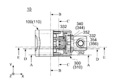
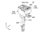
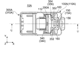
図1に示されるように、本発明の第1の実施の形態によるコネクタ装置10は、コネクタ100と、コネクタ100と嵌合可能な相手側コネクタ300とを備えている。相手側コネクタ300は、電気自動車のような対象物(図示せず)に取り付けられ、電源システム(図示せず)とモーター(図示せず)とに接続されている。コネクタ100が相手側コネクタ300に嵌合すると、コネクタ装置10が電源システムとモーターとの間を接続して、電源システムから供給された電流がモーターに供給される。
(First embodiment)
As shown in FIG. 1, the connector device 10 according to the first embodiment of the present invention includes a connector 100 and a mating connector 300 that can be fitted to the connector 100. The mating connector 300 is attached to an object (not shown) such as an electric vehicle, and is connected to a power supply system (not shown) and a motor (not shown). When the connector 100 is fitted to the mating connector 300, the connector device 10 connects between the power supply system and the motor, and the current supplied from the power supply system is supplied to the motor.

図3に示されるように、相手側コネクタ300は、相手側ハウジング310と、2つの相手側電源端子410と、相手側サブコネクタ420と、ハトメ440とを備えている。 As shown in FIG. 3, the mating connector 300 includes a mating housing 310, two mating power supply terminals 410, a mating sub-connector 420, and an eyelet 440.

図3を参照すると、相手側ハウジング310には、2つの相手側軸部320と、2つの相手側ガイド部380とが形成されている。本実施の形態の相手側軸部320は、回転軸であり、その軸方向はY方向に沿っている。相手側軸部320は、軸方向において互いに離れて位置している。相手側軸部320の軸方向外側の一端には、フランジ322が夫々形成されている。フランジ322の夫々は、軸方向と直交する直交面内において、相手側軸部320よりも少なくとも上下に張り出している。本実施の形態において、相手側ハウジング310は、一対の側壁312と二組の電源端子保持部360とを有している。図3及び図10から理解されるように、電源端子保持部360は、夫々、外側電源端子保持部362と、内側電源端子保持部364と、電源端子保持突起366とを有している。相手側軸部320及びフランジ322は、側壁312と外側電源端子保持部362との間に位置している。相手側軸部320及びフランジ322は、少なくとも一方が外側電源端子保持部362又は側壁312に支持されている。本実施の形態では、相手側軸部320が外側電源端子保持部362に支持され、かつフランジ322が側壁312に支持されている。本実施の形態において直交面はXZ平面である。上下方向はZ方向である。上方は+Z方向であり、下方は−Z方向である。相手側ガイド部380は、突起であり、軸方向において側壁312から内側に突出している。相手側ガイド部380は、軸方向において互いに対向している。 Referring to FIG. 3, the mating housing 310 has two mating shaft portions 320 and two mating guide portions 380. The mating shaft portion 320 of the present embodiment is a rotating shaft, and its axial direction is along the Y direction. The mating shaft portions 320 are located apart from each other in the axial direction. Flange 322 is formed at one end of the mating shaft portion 320 on the outer side in the axial direction. Each of the flanges 322 projects at least above and below the mating shaft portion 320 in an orthogonal plane orthogonal to the axial direction. In the present embodiment, the mating housing 310 has a pair of side walls 312 and two sets of power supply terminal holders 360. As understood from FIGS. 3 and 10, the power supply terminal holding portions 360 each include an outer power supply terminal holding portion 362, an inner power supply terminal holding portion 364, and a power supply terminal holding protrusion 366. The mating shaft portion 320 and the flange 322 are located between the side wall 312 and the outer power source terminal holding portion 362. At least one of the mating shaft portion 320 and the flange 322 is supported by the outer power source terminal holding portion 362 or the side wall 312. In the present embodiment, the mating shaft portion 320 is supported by the outer power source terminal holding portion 362, and the flange 322 is supported by the side wall 312. In the present embodiment, the orthogonal plane is the XZ plane. The vertical direction is the Z direction. The upper side is the +Z direction and the lower side is the -Z direction. The mating guide part 380 is a protrusion and protrudes inward from the side wall 312 in the axial direction. The mating guide portions 380 are opposed to each other in the axial direction.

図6及び図10から理解されるように、相手側ハウジング310は、相手側サブコネクタ保持部367と、二つの第1規制部332と、第1解除部340とを有している。相手側サブコネクタ保持部367は、軸方向と直交する前後方向における後方に壁部368を有している。本実施の形態において、前後方向はX方向である。前方は−X方向であり、後方は+X方向である。第1解除部340は、第1操作方位に操作可能となっている。第1操作方位は、回転軸(相手側軸部320)を中心とする径方向における回転軸320から離れる方位である。換言すれば、第1操作方位は、回転軸320を中心とする円座標系(以下、「特定円座標系」という)において径方向における回転軸320から離れる方位である。より具体的には、本実施の形態の第1操作方位は、後方と一致している。第1解除部340は、第1バネ部342と第1操作部344とを有している。第1バネ部342は、相手側ハウジング310の相手側サブコネクタ保持部367の壁部368から、前後方向において後方に突出し、その後、軸方向及び前後方向の双方と直交する上下方向において上方へ延びている。換言すると、第1バネ部342は、片持ち梁構造を有している。第1操作部344は、第1バネ部342の上端に位置しており、第1バネ部342に支持されている。第1規制部332は、第1操作部344の下端に位置している。図10及び図26に示されるように、第1規制部332の下面は、上下方向と斜交しており、前方且つ下方へ傾斜している。 As understood from FIGS. 6 and 10, the mating housing 310 has a mating sub-connector holding portion 367, two first restricting portions 332, and a first releasing portion 340. The mating sub-connector holding portion 367 has a wall portion 368 on the rear side in the front-back direction orthogonal to the axial direction. In the present embodiment, the front-rear direction is the X direction. The front is the −X direction, and the rear is the +X direction. The first release unit 340 can be operated in the first operation direction. The first operation azimuth is an azimuth away from the rotary shaft 320 in the radial direction around the rotary shaft (the mating shaft portion 320). In other words, the first operation azimuth is an azimuth away from the rotation axis 320 in the radial direction in a circular coordinate system centered on the rotation axis 320 (hereinafter referred to as “specific circular coordinate system”). More specifically, the first operation azimuth of the present embodiment coincides with the back. The first release part 340 has a first spring part 342 and a first operating part 344. The first spring portion 342 projects rearward from the wall portion 368 of the mating sub-connector holding portion 367 of the mating housing 310 in the front-rear direction, and then extends upward in the up-down direction orthogonal to both the axial direction and the front-rear direction. ing. In other words, the first spring portion 342 has a cantilever structure. The first operating portion 344 is located at the upper end of the first spring portion 342 and is supported by the first spring portion 342. The first restricting portion 332 is located at the lower end of the first operating portion 344. As shown in FIGS. 10 and 26, the lower surface of the first restricting portion 332 obliquely intersects with the vertical direction and is inclined forward and downward.

図6及び図10から理解されるように、第1バネ部342は、弾性変形可能である。第1操作部344を操作すると、第1バネ部342を弾性変形させることができ、それによって、第1規制部332を少なくとも前後方向に移動させることができる。 As understood from FIGS. 6 and 10, the first spring portion 342 is elastically deformable. When the first operating portion 344 is operated, the first spring portion 342 can be elastically deformed, whereby the first restricting portion 332 can be moved at least in the front-rear direction.

図10に示されるように、相手側ハウジング310は、さらに後壁350を有している。後壁350は、前後方向において後側に位置し、上下方向に延びている。後壁350には、2つの第2規制部352と、1つの嵌合規制部(付加的規制部)354とが形成されている。第2規制部352と嵌合規制部354とは、ともに後方に突出している。嵌合規制部354は、第2規制部352よりも後方へ突出している。図3に示されるように、第2規制部352は、軸方向において、嵌合規制部354の外側に位置している。図10に示されるように、第2規制部352の下面は上下方向と直交しており、第2規制部352の上面は上下方向と斜交している。一方、嵌合規制部354の下面は、図3から理解されるように、上下方向と斜交している。嵌合規制部354の下面は、後方へ傾斜している。また、図11に示されるように、嵌合規制部354の上面である突当面(第2突当面)356もまた上下方向と斜交している。換言すると、嵌合規制部354の突当面356は、上下方向に直交する水平面と交差している。突当面356は、前方且つ下方へ傾斜している。 As shown in FIG. 10, the mating housing 310 further has a rear wall 350. The rear wall 350 is located on the rear side in the front-rear direction and extends in the vertical direction. On the rear wall 350, two second restricting portions 352 and one fitting restricting portion (additional restricting portion) 354 are formed. The second restricting portion 352 and the fitting restricting portion 354 both project rearward. The fitting restricting portion 354 projects rearward from the second restricting portion 352. As shown in FIG. 3, the second restricting portion 352 is located outside the fitting restricting portion 354 in the axial direction. As shown in FIG. 10, the lower surface of the second restricting portion 352 is orthogonal to the vertical direction, and the upper surface of the second restricting portion 352 is oblique to the vertical direction. On the other hand, the lower surface of the fitting restricting portion 354 obliquely intersects with the vertical direction, as can be understood from FIG. The lower surface of the fitting restricting portion 354 is inclined rearward. Further, as shown in FIG. 11, an abutting surface (second abutting surface) 356 which is an upper surface of the fitting restricting portion 354 also obliquely intersects with the vertical direction. In other words, the abutting surface 356 of the fitting restricting portion 354 intersects the horizontal plane orthogonal to the vertical direction. The abutting surface 356 is inclined forward and downward.

図8及び図10に示されるように、相手側電源端子410は、所謂ソケットコンタクトである。図8、図16、図24及び図32に示されるように、各相手側電源端子410には、接点412が設けられている。本実施の形態の接点412は、少なくとも軸方向の外側に移動可能である。図8及び図10に示されるように、相手側電源端子410には夫々電源ケーブル500が接続されている。相手側電源端子410は、電源端子保持部360の電源端子保持突起366により相手側ハウジング310の電源端子保持部360に保持されており、相手側ハウジング310に対して相対移動できない。相手側電源端子410は、軸方向において互いに離れて位置している。 As shown in FIGS. 8 and 10, the mating power supply terminal 410 is a so-called socket contact. As shown in FIGS. 8, 16, 24, and 32, a contact 412 is provided on each mating power supply terminal 410. The contact 412 of the present embodiment is movable at least outward in the axial direction. As shown in FIGS. 8 and 10, the power cables 500 are connected to the mating power terminals 410, respectively. The mating power supply terminal 410 is held by the power supply terminal holding projection 360 of the power supply terminal holding portion 360 on the power supply terminal holding portion 360 of the mating housing 310 and cannot move relative to the mating housing 310. The mating power supply terminals 410 are located apart from each other in the axial direction.

図17、図25及び図33に示されるように、相手側サブコネクタ420は、サブハウジング424と、2つの相手側検知端子430とを備えている。相手側検知端子430は、サブハウジング424に保持され固定されている。また、相手側サブコネクタ420は、相手側ハウジング310に保持され固定されている。即ち、相手側検知端子430は、相手側サブコネクタ420のサブハウジング424を介して、相手側ハウジング310に保持されており、相手側ハウジング310に対して相対移動できない。詳しくは、相手側検知端子430は、軸方向において互いに離れて位置しており、相手側検知端子430には、信号線510が夫々接続されている。また、各相手側検知端子430には、接点432が設けられている。本実施の形態の接点432は、少なくとも軸方向の内側に移動可能である。 As shown in FIGS. 17, 25 and 33, the mating sub connector 420 includes a sub housing 424 and two mating detection terminals 430. The mating side detection terminal 430 is held and fixed to the sub housing 424. The mating sub connector 420 is held and fixed to the mating housing 310. That is, the mating side detection terminal 430 is held by the mating side housing 310 via the sub-housing 424 of the mating side sub-connector 420 and cannot move relative to the mating side housing 310. Specifically, the counterpart detection terminals 430 are located apart from each other in the axial direction, and the signal lines 510 are connected to the counterpart detection terminals 430, respectively. Further, a contact point 432 is provided on each of the partner side detection terminals 430. The contact 432 of this embodiment is movable at least inward in the axial direction.

図4、図20及び図28に示されるように、コネクタ100は、相手側コネクタ300に対して、第1状態、第2状態及び第3状態の3状態をとりうるものである。より詳しくは、図4、図12、図20及び図28に示されるように、コネクタ100は、相手側コネクタ300に対して、第1状態、第2状態、第3状態及び第4状態の4状態をとりうるものである。第1状態とは、コネクタ100が、相手側コネクタ300に対して、図20から図27までの図に示されるように相対的に位置している状態である。第2状態とは、コネクタ100が、相手側コネクタ300に対して、図28から図35までの図に示されるように相対的に位置している状態である。第3状態とは、コネクタ100が、相手側コネクタ300に対して、図4から図11までの図に示されるように相対的に位置している状態である。第4状態とは、コネクタ100が、相手側コネクタ300に対して、図12から図19までの図に示されるように相対的に位置している状態である。ここで第2状態は、第1状態と第3状態との間にあり、より詳しくは第1状態と第4状態との間にある。また、第4状態は、第1状態と第3状態との間にあり、より詳しくは第2状態と第3状態との間にある。 As shown in FIG. 4, FIG. 20 and FIG. 28, the connector 100 can take three states of the mating connector 300: a first state, a second state and a third state. More specifically, as shown in FIG. 4, FIG. 12, FIG. 20, and FIG. 28, the connector 100 is different from the mating connector 300 in the first state, the second state, the third state, and the fourth state. It can be in a state. The first state is a state in which the connector 100 is relatively positioned with respect to the mating connector 300 as shown in FIGS. 20 to 27. The second state is a state in which the connector 100 is positioned relative to the mating connector 300 as shown in the drawings of FIGS. 28 to 35. The third state is a state in which the connector 100 is relatively positioned with respect to the mating connector 300 as shown in FIGS. 4 to 11. The fourth state is a state in which the connector 100 is relatively positioned with respect to the mating connector 300 as shown in FIGS. 12 to 19. Here, the second state is between the first state and the third state, and more specifically, between the first state and the fourth state. The fourth state is between the first state and the third state, and more specifically, it is between the second state and the third state.

図2に示されるように、コネクタ100は、ハウジング110と、電源端子210と、検知端子230とを備えている。 As shown in FIG. 2, the connector 100 includes a housing 110, a power supply terminal 210, and a detection terminal 230.

図2及び図7を参照すると、ハウジング110には、2つの軸部120と、2つの誘導部124と、2つの被ガイド部180とが形成されている。本実施の形態の軸部120は、軸受である。軸部120は、軸方向において互いに離れて位置している。軸部120には、フランジガイド部122が形成されている。フランジガイド部122は、直交面内に延びている。誘導部124は、軸部120に対応して設けられている。図1及び図7から理解されるように、誘導部124は、回転軸320を軸部120まで夫々誘導するための溝であり、特定円座標系において径方向に延びている。図2に示されるように、本実施の形態の誘導部124は、軸方向においてハウジング110を貫通している。被ガイド部180は、軸方向に凹んだ溝であり、直交面内において円弧状の形状を有している。本実施の形態の被ガイド部180は、軸方向において底を有する溝であるが、底を有さないもの(即ち、軸方向においてハウジング110を貫通しているもの)であってもよい。 Referring to FIGS. 2 and 7, the housing 110 includes two shafts 120, two guides 124, and two guided parts 180. The shaft portion 120 of the present embodiment is a bearing. The shaft portions 120 are located apart from each other in the axial direction. A flange guide portion 122 is formed on the shaft portion 120. The flange guide portion 122 extends in the orthogonal plane. The guide portion 124 is provided corresponding to the shaft portion 120. As can be seen from FIGS. 1 and 7, the guide portion 124 is a groove for guiding the rotary shaft 320 to the shaft portion 120, and extends in the radial direction in the specific circular coordinate system. As shown in FIG. 2, the guide portion 124 of the present embodiment penetrates the housing 110 in the axial direction. The guided portion 180 is a groove that is recessed in the axial direction and has an arcuate shape in the orthogonal plane. The guided portion 180 of the present embodiment is a groove having a bottom in the axial direction, but it may be a groove having no bottom (that is, one that penetrates the housing 110 in the axial direction).

図8を参照すると、ハウジング110には、2つの第1被規制部132と、2つのリード部134とが形成されている。図8及び図11に示されるように、ハウジング110には、開口部112が形成されており、開口部112を通して第1被規制部132を視認することができる。図26から理解されるように、コネクタ100が第1状態にあるとき、第1被規制部132は、後方に向かって突出している。図26に示されるように、第1被規制部132の上面は、上下方向に斜交し、前方且つ下方に傾斜している。図10に示されるように、リード部134は、コネクタ100が第3状態にあるとき、後方且つ下方に傾斜している。 Referring to FIG. 8, the housing 110 is provided with two first regulated portions 132 and two lead portions 134. As shown in FIGS. 8 and 11, an opening 112 is formed in the housing 110, and the first restricted portion 132 can be visually recognized through the opening 112. As understood from FIG. 26, when the connector 100 is in the first state, the first regulated portion 132 projects rearward. As shown in FIG. 26, the upper surface of the first regulated portion 132 obliquely intersects in the vertical direction and is inclined forward and downward. As shown in FIG. 10, the lead portion 134 is inclined rearward and downward when the connector 100 is in the third state.

図2、図9、図10及び図11から理解されるように、本実施の形態のハウジング110には、基部140と、第2解除部150と、2つの第2被規制部160と、嵌合被規制部(付加的被規制部)170とが形成されている。第2解除部150は、第2操作方位に操作可能となっている。第2操作方位は、回転軸320を中心とする径方向における回転軸320から離れる方位である。換言すれば、第2操作方位は、特定円座標系において径方向における回転軸320から離れる方位である。より具体的には、本実施の形態において、コネクタ100が第1状態にあるとき、第2操作方位は後方と一致している。即ち、コネクタ100が第1状態にあるとき、第1操作方位と、第2操作方位とは一致している。第2解除部150は、弾性変形可能な2つの第2バネ部152と、第2バネ部152に支持される第2操作部154とを有している。第2バネ部152は、第2被規制部160及び嵌合被規制部170を支持している。 As will be understood from FIGS. 2, 9, 10, and 11, the housing 110 according to the present embodiment includes a base portion 140, a second releasing portion 150, two second regulated portions 160, and a fitting portion. A combined regulated portion (additionally regulated portion) 170 is formed. The second release unit 150 can be operated in the second operation direction. The second operation azimuth is an azimuth away from the rotary shaft 320 in the radial direction around the rotary shaft 320. In other words, the second operation direction is the direction away from the rotation axis 320 in the radial direction in the specific circular coordinate system. More specifically, in the present embodiment, when connector 100 is in the first state, the second operation azimuth coincides with the rear. That is, when the connector 100 is in the first state, the first operation direction and the second operation direction are the same. The second release part 150 has two elastically deformable second spring parts 152 and a second operation part 154 supported by the second spring parts 152. The second spring portion 152 supports the second regulated portion 160 and the fitting regulated portion 170.

図9、図10、図11、図26及び図27から理解されるように、第2バネ部152は、基部140から第3所定方位に向かって延びる片持ち梁構造を有している。具体的には、第2バネ部152は、コネクタ100が第1状態にあるとき、基部140から前方へ突き出した後、上方へ延びている。また、第2バネ部152は、第2所定方位に厚みを有している。第2バネ部152は、第2操作部154によって互いに連結されている。第2操作部154は、第2バネ部152の端部同士を連結している。嵌合被規制部170は、コネクタ100が第1状態にあるとき、上下方向において、第2操作部154の下方に位置している。図18及び図22に示されるように、第2操作部154には、逃がし部156が設けられている。逃がし部156は、第2操作部154の一部を、第2所定方位へ向かって凹ませて形成されている。換言すると、逃がし部156は、コネクタ100が第1状態にあるとき、後方へ凹んでいる。本実施の形態において、コネクタ100が第1状態にあるとき、第3所定方位は上方に一致する。 As can be understood from FIGS. 9, 10, 11, 26 and 27, the second spring portion 152 has a cantilever structure extending from the base portion 140 toward the third predetermined orientation. Specifically, when the connector 100 is in the first state, the second spring portion 152 projects forward from the base portion 140 and then extends upward. Further, the second spring portion 152 has a thickness in the second predetermined orientation. The second spring portions 152 are connected to each other by the second operating portion 154. The second operating portion 154 connects the end portions of the second spring portion 152 to each other. The fitting-restricted portion 170 is located below the second operation portion 154 in the up-down direction when the connector 100 is in the first state. As shown in FIGS. 18 and 22, the second operation portion 154 is provided with a relief portion 156. The escape portion 156 is formed by denting a part of the second operation portion 154 toward the second predetermined orientation. In other words, the escape portion 156 is recessed rearward when the connector 100 is in the first state. In the present embodiment, when connector 100 is in the first state, the third predetermined orientation matches upward.

図9に示されるように、嵌合被規制部170は、軸方向において第2バネ部152の間に位置し、第2バネ部152に支持されている。また、嵌合被規制部170は、図26に示されるように、第2所定方位において第2バネ部152の厚み内に位置している。換言すると、コネクタ100が第1状態にあるとき、嵌合被規制部170は、前後方向において、第2バネ部152の範囲内に位置している。本実施の形態では、嵌合被規制部170の全体が第2所定方位において第2バネ部152の厚み内に位置しているが、本発明はこれに限られない。嵌合被規制部170は、その一部が第2所定方位において第2バネ部152の範囲内に位置していればよい。換言すると、嵌合被規制部170は、第2所定方位において第2バネ部152の厚み内に位置する部位を有していればよい。さらに、嵌合被規制部170には、第3所定方位の逆方位である第4所定方位又は第2所定方位と第4所定方位の合成方位に向いている突当面(第1突当面)172が設けられている。換言すると、突当面172は、第2所定方位の逆方位である第5所定方位に向かう成分は有していない。本実施の形態では、突当面172は、第4所定方位に向いている。本実施の形態において、コネクタ100が第1状態にあるとき、第4所定方位は下方に一致し、第5所定方位は前方に一致する。 As shown in FIG. 9, the fitting-restricted portion 170 is located between the second spring portions 152 in the axial direction and is supported by the second spring portions 152. Further, the fitting-restricted portion 170 is located within the thickness of the second spring portion 152 in the second predetermined orientation as shown in FIG. In other words, when the connector 100 is in the first state, the fitting-restricted portion 170 is located within the range of the second spring portion 152 in the front-rear direction. In the present embodiment, the entire fitting restricted portion 170 is located within the thickness of the second spring portion 152 in the second predetermined orientation, but the present invention is not limited to this. The fitting restricted portion 170 may be partially located within the range of the second spring portion 152 in the second predetermined orientation. In other words, the fitting-restricted portion 170 may have a portion located within the thickness of the second spring portion 152 in the second predetermined orientation. Further, the fitting restricted portion 170 has an abutment surface (first abutment surface) 172 facing the fourth predetermined orientation, which is the reverse orientation of the third predetermined orientation, or the combined orientation of the second predetermined orientation and the fourth predetermined orientation. Is provided. In other words, the abutting surface 172 does not have a component directed to the fifth predetermined azimuth, which is the opposite azimuth of the second predetermined azimuth. In the present embodiment, the abutting surface 172 faces the fourth predetermined orientation. In the present embodiment, when connector 100 is in the first state, fourth predetermined azimuth matches downward and fifth predetermined azimuth matches forward.

図9及び図26に示されるように、第2被規制部160は、第2バネ部152の軸方向の内側に位置し、第2バネ部152に支持されている。詳しくは、第2被規制部160は、コネクタ100が第1状態にあるとき、第2バネ部152から前方へ突出している。図11に示されるように、コネクタ100が第3状態にあるとき、第2被規制部160は嵌合被規制部170よりも下方へ突き出している。 As shown in FIGS. 9 and 26, the second regulated portion 160 is located inside the second spring portion 152 in the axial direction and is supported by the second spring portion 152. Specifically, the second regulated portion 160 projects forward from the second spring portion 152 when the connector 100 is in the first state. As shown in FIG. 11, when the connector 100 is in the third state, the second regulated portion 160 projects downward from the fitting regulated portion 170.

図11及び図18から理解されるように、第2操作部154を操作すると、第2バネ部152を弾性変形させることができ、それによって、第2被規制部160及び嵌合被規制部170を特定円座標系において少なくとも径方向に移動させることができる。換言すると、第2操作部154を操作して第2バネ部152を弾性変形させると、第2被規制部160及び嵌合被規制部170を少なくとも第2所定方位へ移動させることができる。このように、第2操作部154は、第2被規制部160を移動させるだけでなく、嵌合被規制部170をも移動させることができる。 As can be understood from FIGS. 11 and 18, when the second operation portion 154 is operated, the second spring portion 152 can be elastically deformed, whereby the second regulated portion 160 and the fitting regulated portion 170. Can be moved at least in the radial direction in the specific circular coordinate system. In other words, when the second operation portion 154 is operated to elastically deform the second spring portion 152, the second restricted portion 160 and the fitting restricted portion 170 can be moved at least in the second predetermined direction. In this way, the second operation portion 154 can move not only the second regulated portion 160 but also the fitting regulated portion 170.

図20から図23、図26及び図27までに示されるように、ハウジング110には、阻止部390が更に設けられている。本実施の形態の阻止部390は、コネクタ100が第1状態にあるときに、第1操作部344と第2操作部154との間において軸方向に延びるように設けられた梁である。即ち、本実施の形態の阻止部390は、コネクタ100が第1状態にあるとき、前後方向において第1操作部344と第2操作部154との間に位置している。より具体的には、コネクタ100が第1状態にあるとき、本実施の形態の阻止部390は、前後方向において第1操作部344の直後に位置しており、且つ、前後方向において第2操作部154の前方に位置している。コネクタ100が第1状態にあるとき、本実施の形態の阻止部390の上端は、上下方向において第1操作部344の上端よりも上方に位置しており、且つ、上下方向において第2操作部154の上端と概略同じ位置に位置している。コネクタ100が第1状態にあるとき、本実施の形態の阻止部390の前面は前後方向と交差しており、阻止部390の前面の下端は上下方向において第1操作部344の上端よりも上方に位置している。 As shown in FIGS. 20 to 23, 26 and 27, the housing 110 is further provided with a blocking portion 390. The blocking portion 390 of the present embodiment is a beam provided so as to extend in the axial direction between the first operating portion 344 and the second operating portion 154 when the connector 100 is in the first state. That is, the blocking portion 390 of the present embodiment is located between the first operating portion 344 and the second operating portion 154 in the front-rear direction when the connector 100 is in the first state. More specifically, when the connector 100 is in the first state, the blocking portion 390 of the present embodiment is located immediately after the first operating portion 344 in the front-rear direction, and the second operating portion in the front-rear direction. It is located in front of the portion 154. When the connector 100 is in the first state, the upper end of the blocking portion 390 of the present embodiment is located above the upper end of the first operating portion 344 in the vertical direction, and the second operating portion in the vertical direction. It is located at substantially the same position as the upper end of 154. When the connector 100 is in the first state, the front surface of the blocking portion 390 of the present embodiment intersects the front-rear direction, and the lower end of the front surface of the blocking portion 390 is above the upper end of the first operating portion 344 in the vertical direction. Is located in.

図2に示されるように、電源端子210は、2つのブレード部212と、それらを連結する連結部214とを備えている。図16、図24及び図32に示されるように、電源端子210は、2つの相手側電源端子410の間を接続するためのものである。図2に示されるように、ブレード部212は、直交面内に延びている。ブレード部212の先端側のエッジは面取りされている。図10から理解されるように、連結部214は、ハウジング110に取り付けられ保持されている。具体的には、本実施の形態の電源端子210は、ハウジング110に対して相対移動できないように固定されている。 As shown in FIG. 2, the power supply terminal 210 includes two blade portions 212 and a connecting portion 214 that connects them. As shown in FIG. 16, FIG. 24, and FIG. 32, the power supply terminal 210 is for connecting between two mating power supply terminals 410. As shown in FIG. 2, the blade portion 212 extends in the orthogonal plane. The edge on the front end side of the blade portion 212 is chamfered. As can be seen from FIG. 10, the connecting portion 214 is attached to and held by the housing 110. Specifically, the power supply terminal 210 of the present embodiment is fixed so as not to move relative to the housing 110.

図2に示されるように、検知端子230は、2つの接触部232と、それらを連結する連結部234とを備えている。図2、図4、図8、図9から理解されるように、検知端子230は、ハウジング110に保持されている。本実施の形態の検知端子230は、特許文献1のものとは異なり、ハウジング110に対して相対移動できないように固定されている。 As shown in FIG. 2, the detection terminal 230 includes two contact portions 232 and a connecting portion 234 that connects them. As understood from FIGS. 2, 4, 8, and 9, the detection terminal 230 is held by the housing 110. The detection terminal 230 of the present embodiment is fixed so as not to move relative to the housing 110, unlike that of Patent Document 1.

図1から理解されるように、軸部120と電源端子210との間の距離は、軸部120と検知端子230との間の距離よりも短い。このため、コネクタ装置10全体の大きさを大きくすることなく、電源端子210の相手側コネクタ300に対する接続を検知端子230の相手側コネクタ300に対する接続よりも先に行うことができる。 As can be seen from FIG. 1, the distance between the shaft portion 120 and the power supply terminal 210 is shorter than the distance between the shaft portion 120 and the detection terminal 230. Therefore, the connection of the power supply terminal 210 to the mating connector 300 can be performed before the connection of the detection terminal 230 to the mating connector 300 without increasing the size of the entire connector device 10.

図1、図4、図12、図20及び図28から理解されるように、軸部120と相手側軸部320とを組み合わせることにより、コネクタ100は、相手側コネクタ300に対して第1状態と第3状態との間の状態をとりつつ回転軸(相手側軸部320)の周りに回転可能となっている。第1状態は、前述のように図20に示される状態であり、コネクタ100は横たわった状態にある。第3状態は、図4に示される状態であり、コネクタ100は立った状態にある。図4、図12、図20及び図28から理解されるように、コネクタ100が第1状態と第3状態との間の状態であるとき、コネクタ100は上下方向において相手側コネクタ300の上方に位置している。図7及び図8から理解されるように、回転軸320から第1被規制部132までの距離は、回転軸320から第2被規制部160までの距離よりも短い。 As can be understood from FIGS. 1, 4, 12, 20, and 28, by combining the shaft portion 120 and the mating shaft portion 320, the connector 100 is in the first state with respect to the mating connector 300. It is possible to rotate around the rotating shaft (the mating shaft portion 320) while taking a state between the third state and the third state. The first state is the state shown in FIG. 20 as described above, and the connector 100 is in the lying state. The third state is the state shown in FIG. 4, and the connector 100 is in a standing state. As understood from FIGS. 4, 12, 20, and 28, when the connector 100 is in the state between the first state and the third state, the connector 100 is positioned above the mating connector 300 in the vertical direction. positioned. As understood from FIGS. 7 and 8, the distance from the rotary shaft 320 to the first regulated portion 132 is shorter than the distance from the rotary shaft 320 to the second regulated portion 160.

図2、図7、図15、図23及び図31から理解されるように、コネクタ100が第1状態と第3状態との間の状態をとりつつ回転するとき、フランジガイド部122は、軸方向においてフランジ322の内側に位置していると共にフランジ322と対向しており、直交面内におけるフランジ322の移動をガイドしている。また、コネクタ100を回転させる際には、相手側ガイド部380の突起が被ガイド部180の溝内を移動して、回転をガイドしている。 As can be understood from FIGS. 2, 7, 15, 23, and 31, when the connector 100 rotates while taking the state between the first state and the third state, the flange guide portion 122 may not rotate. It is located inside the flange 322 in the direction and faces the flange 322, and guides the movement of the flange 322 in the orthogonal plane. Further, when the connector 100 is rotated, the protrusion of the mating guide portion 380 moves in the groove of the guided portion 180 to guide the rotation.

図1及び図4から図7までの図から理解されるように、コネクタ100は、立てた状態(長手方向を上下方向に合わせた状態)で相手側コネクタ300の上方から上下方向に沿って相手側コネクタ300に対して取り付けられる。このとき、誘導部124は、相手側軸部320を受容して上下方向に沿って軸部120までガイドする。そのため、図7に示されるように、コネクタ100が第3状態にあるとき、誘導部124は、上下方向に沿って延びており、下側に向かって開口している。図8に示されるように、コネクタ100が第3状態にあるとき、電源端子210は相手側電源端子410に接続されていない。また、図7及び図9から理解されるように、検知端子230は相手側検知端子430に接続されていない。 As can be understood from FIGS. 1 and 4 to 7, the connector 100 is a mating connector from above the mating connector 300 in the upright state (the longitudinal direction is vertically aligned). It is attached to the side connector 300. At this time, the guide portion 124 receives the mating shaft portion 320 and guides it to the shaft portion 120 in the vertical direction. Therefore, as shown in FIG. 7, when the connector 100 is in the third state, the guide portion 124 extends in the up-down direction and opens downward. As shown in FIG. 8, when the connector 100 is in the third state, the power supply terminal 210 is not connected to the mating power supply terminal 410. Further, as understood from FIGS. 7 and 9, the detection terminal 230 is not connected to the counterpart detection terminal 430.

図18に示されるように、第3状態から第4状態までコネクタ100を遷移させるように回転させると、嵌合被規制部170が嵌合規制部354に、第2所定方位における第2バネ部152の厚み内の位置において突き当る。換言すると、嵌合被規制部170の第2所定方位における第2バネ部152の厚み内に位置する部位が嵌合規制部354に突き当たる。これにより、コネクタ100が第4状態を越えて第1状態に向けて遷移することが一旦規制される。このとき、嵌合被規制部170の突当面172は、嵌合規制部354の突当面356と対向している。前述のように、嵌合被規制部170の突当面172は、第4所定方位又は第2所定方位と第4所定方位の合成方位に向いている。一方、嵌合規制部354の突当面356は、コネクタ100が第4状態にあるとき、第3所定方位と第5所定方位との合成方位に向いている。換言すると、突当面356は、第2所定方位に向かう成分は有していない。加えて、嵌合被規制部170は、第2所定方位において、第2バネ部152の厚み内に位置している。このため、コネクタ100を第1状態に向かって遷移するように無理に回転させようとしても、嵌合規制部354による嵌合被規制部170の規制が解除される方向に嵌合被規制部170がずれるように第2バネ部152が弾性変形したりすることがない。よって、コネクタ100は、嵌合規制部354による嵌合被規制部170の規制を解除する操作を行わない限り、第4状態に維持される。 As shown in FIG. 18, when the connector 100 is rotated so as to transition from the third state to the fourth state, the fitting restricted portion 170 causes the fitting restricted portion 354 to move to the second spring portion in the second predetermined orientation. It abuts at a position within the thickness of 152. In other words, a portion located within the thickness of the second spring portion 152 in the second predetermined azimuth of the fitting restricted portion 170 abuts on the fitting restricted portion 354. As a result, the transition of the connector 100 beyond the fourth state toward the first state is once restricted. At this time, the abutting surface 172 of the fitting restricted portion 170 faces the abutting surface 356 of the fitting restricted portion 354. As described above, the abutting surface 172 of the fitting restricted portion 170 faces the fourth predetermined azimuth or the combined azimuth of the second predetermined azimuth and the fourth predetermined azimuth. On the other hand, the abutting surface 356 of the fitting restricting portion 354 faces the combined orientation of the third predetermined orientation and the fifth predetermined orientation when the connector 100 is in the fourth state. In other words, the abutting surface 356 does not have a component directed toward the second predetermined azimuth. In addition, the fitting regulated portion 170 is located within the thickness of the second spring portion 152 in the second predetermined orientation. Therefore, even if the connector 100 is forcibly rotated so as to transition toward the first state, the fitting restricted portion 170 is released in the direction in which the restriction of the fitting restricted portion 170 by the fitting restricting portion 354 is released. The second spring portion 152 does not elastically deform so as to be displaced. Therefore, the connector 100 is maintained in the fourth state unless the fitting restricting portion 354 releases the restriction of the fitting restricted portion 170.

図16及び図17に示されるように、コネクタ100が第4状態にあるとき、電源端子210は相手側電源端子410に接続されるが、検知端子230は未だ相手側検知端子430まで届いていない。即ち、図12から図17までに示されるように、コネクタ100が第4状態にあるとき、電源端子210は相手側電源端子410に接続されているが、検知端子230は相手側検知端子430に接続されていない。検知端子230が相手側検知端子430に接続されていないことから、信号線510間はつながっていない。そのため、電源システム(図示せず)においては、コネクタ100が相手側コネクタ300に対して完全に嵌合していないことを検知することができ、電源端子210が相手側電源端子410同士を物理的に接続していても電源ケーブル500に電流を流さないよう制御できる。 As shown in FIGS. 16 and 17, when the connector 100 is in the fourth state, the power supply terminal 210 is connected to the mating power supply terminal 410, but the detection terminal 230 has not reached the mating detection terminal 430 yet. .. That is, as shown in FIGS. 12 to 17, when the connector 100 is in the fourth state, the power supply terminal 210 is connected to the mating power supply terminal 410, but the detection terminal 230 is connected to the mating detection terminal 430. Not connected. Since the detection terminal 230 is not connected to the partner detection terminal 430, the signal lines 510 are not connected. Therefore, in the power supply system (not shown), it is possible to detect that the connector 100 is not completely fitted to the mating connector 300, and the power supply terminal 210 physically connects the mating power supply terminals 410 to each other. It is possible to control so that no current flows through the power supply cable 500 even if the power cable is connected to.

図2及び図8から理解されるように、電源端子210のブレード部212は、コネクタ100が回転している間、直交面内を移動する。図7及び図8を参照すると、フランジガイド部122がフランジ322をガイドすることから、ブレード部212は適切に直交面内を移動することができ、相手側電源端子410内まで達することができる。 As understood from FIGS. 2 and 8, the blade portion 212 of the power supply terminal 210 moves in the orthogonal plane while the connector 100 rotates. Referring to FIGS. 7 and 8, since the flange guide part 122 guides the flange 322, the blade part 212 can appropriately move in the orthogonal plane and reach the inside of the mating power supply terminal 410.

また、ブレード部212が相手側電源端子410に接続される際、ブレード部212のエッジが面取りされているので、ブレード部212はスムーズに相手側電源端子410内に受容される。本実施の形態においては、電源端子210のブレード部212は、相手側電源端子410内において、相手側電源端子410の接点412に対して軸方向において接触している。 Further, when the blade part 212 is connected to the mating power supply terminal 410, the edge of the blade part 212 is chamfered, so that the blade part 212 is smoothly received in the mating power supply terminal 410. In the present embodiment, the blade portion 212 of the power supply terminal 210 is in axial contact with the contact 412 of the mating power supply terminal 410 inside the mating power supply terminal 410.

図18から理解されるように、コネクタ100が第4状態にあるとき、リード部134は、第1解除部340の前面を押し、第1バネ部342を弾性変形させている。第1バネ部342が弾性変形することにより、第1規制部332は、コネクタ100が第3状態にあるときよりも、少なくとも後方へ移動している。このとき、上下方向において、第1被規制部132の上面は、第1規制部332の下面よりも上方に位置している。即ち、第1被規制部132は第1規制部332によって規制されていない。 As will be understood from FIG. 18, when the connector 100 is in the fourth state, the lead portion 134 pushes the front surface of the first release portion 340 and elastically deforms the first spring portion 342. Due to the elastic deformation of the first spring portion 342, the first restricting portion 332 is moved at least rearward as compared with when the connector 100 is in the third state. At this time, the upper surface of the first restricted portion 132 is located above the lower surface of the first restricted portion 332 in the vertical direction. That is, the first restricted portion 132 is not restricted by the first restricted portion 332.

図19に示されるように、コネクタ100が第4状態にあるとき、上下方向において、第2被規制部160の上面は第2規制部352よりも上方に位置している。即ち、第2被規制部160は、第2規制部352によって規制されていない。 As shown in FIG. 19, when the connector 100 is in the fourth state, the upper surface of the second regulated portion 160 is located above the second regulated portion 352 in the vertical direction. That is, the second restricted portion 160 is not restricted by the second restricting portion 352.

図18を参照して上述したように、コネクタ100が第4状態にあるとき、嵌合被規制部170が嵌合規制部354に突き当たり、コネクタ100の移動が一時的に規制(付加的規制)されている。図18から理解されるように、コネクタ100が第4状態にあるとき、第2操作部154を操作すると、嵌合規制部354による嵌合被規制部170の規制が解除される。詳しくは、第2操作部154を、特定円座標系において径方向における回転軸320から離れる方位へ移動させると、第2バネ部152が弾性変形し、それによって嵌合被規制部170が特定円座標系において径方向における回転軸320から離れる方位へ移動する。その結果、上記付加的規制が解除され、コネクタ100は、図20に示す第1状態へ向かって遷移可能となる。このように、第2解除部150は、嵌合規制部354による嵌合被規制部170の規制を解除する付加的解除部を兼ねている。つまり、第2操作部154は付加的操作部として機能し、第2バネ部152は片持ち梁部として機能する。換言すると、付加的操作部と片持ち梁部とは第2解除部150を構成している。 As described above with reference to FIG. 18, when the connector 100 is in the fourth state, the fitting restricted portion 170 hits the fitting restricted portion 354, and the movement of the connector 100 is temporarily restricted (additional restriction). Has been done. As understood from FIG. 18, when the connector 100 is in the fourth state, when the second operation portion 154 is operated, the restriction of the fitting restricted portion 170 by the fitting restriction portion 354 is released. Specifically, when the second operation unit 154 is moved in the radial direction away from the rotation shaft 320 in the specific circular coordinate system, the second spring portion 152 is elastically deformed, whereby the fitting restricted portion 170 causes the specific circle to move. The coordinate system moves in a direction away from the rotation axis 320 in the radial direction. As a result, the additional restriction is released, and the connector 100 can transition to the first state shown in FIG. In this way, the second releasing portion 150 also serves as an additional releasing portion that releases the restriction of the fitting restricted portion 170 by the fitting restriction portion 354. That is, the second operating portion 154 functions as an additional operating portion, and the second spring portion 152 functions as a cantilever portion. In other words, the additional operation part and the cantilever part constitute the second releasing part 150.

図20から図25までに示されるように、コネクタ100が第1状態にあるとき、コネクタ100は、電源端子210及び検知端子230は相手側電源端子410及び相手側検知端子430に夫々接続されている。そのため、電源システム(図示せず)は、コネクタ100が相手側コネクタ300に対して完全に嵌合したことを検知することができるので、電源ケーブル500に対して電流を流すように制御することができる。 As shown in FIGS. 20 to 25, when the connector 100 is in the first state, in the connector 100, the power supply terminal 210 and the detection terminal 230 are connected to the mating power supply terminal 410 and the mating detection terminal 430, respectively. There is. Therefore, the power supply system (not shown) can detect that the connector 100 is completely fitted to the mating connector 300, and thus can control the power supply cable 500 so that a current flows. it can.

本実施の形態においては、電源端子210は、コネクタ100が第1状態と第4状態との間にあるとき、相手側電源端子410に接続し続けている。図24に示されるように、コネクタ100が第1状態にあるとき、電源端子210は、前後方向と直交する面内(YZ平面内)において、角張った逆U字状の断面形状を有している。 In the present embodiment, the power supply terminal 210 continues to be connected to the mating power supply terminal 410 when the connector 100 is between the first state and the fourth state. As shown in FIG. 24, when the connector 100 is in the first state, the power supply terminal 210 has an angular inverted U-shaped cross-sectional shape in a plane (YZ plane) orthogonal to the front-back direction. There is.

一方、図17及び図25から理解されるように、検知端子230は、コネクタ100が第1状態に至るまで、相手側検知端子430には接続されておらず、コネクタ100が第1状態に至ると、相手側検知端子430の接点432に接続される。なお、図25に示されるように、コネクタ100が第1状態にあるとき、検知端子230は、前後方向と直交する面内(YZ平面内)において、角張ったU字状の断面形状を有している。 On the other hand, as can be understood from FIGS. 17 and 25, the detection terminal 230 is not connected to the mating detection terminal 430 until the connector 100 reaches the first state, and the connector 100 reaches the first state. Is connected to the contact 432 of the partner side detection terminal 430. Note that, as shown in FIG. 25, when the connector 100 is in the first state, the detection terminal 230 has an angular U-shaped cross-sectional shape in a plane (YZ plane) orthogonal to the front-rear direction. ing.

図18及び図26から理解されるように、コネクタ100第4状態から第1状態へ移動する間に、第1被規制部132は、第1規制部332を乗り越え、上下方向において第1規制部332の下側へ移動する。図26に示されるように、コネクタ100が第1状態にあるとき、第1被規制部132は、上下方向において第1規制部332の下側に位置する。また、図26から理解されるように、第1被規制部132の少なくとも一部は、上下方向に沿って見たとき第1規制部332と重複する。これにより、コネクタ100を第1状態から第2状態へ向かって遷移させようとすると、第1被規制部132が第1規制部332に突き当り、コネクタ100は第2状態に遷移しないように規制される。なお、図26において、第1規制部332と第1被規制部132との間には隙間が存在する。しかしながら、コネクタ100が第1状態にあるとき、第1規制部332と第1被規制部132とが互いに接触するようにしてもよい。そうすれば、コネクタ100は、第1状態を越えて第2状態に向かって回転することができない。その結果、コネクタ100の相手側コネクタ300に対するガタツキを抑えることができる。 As understood from FIGS. 18 and 26, while the connector 100 is moving from the fourth state to the first state, the first regulated portion 132 gets over the first regulation portion 332, and the first regulation portion in the up-down direction. 332 moves to the lower side. As shown in FIG. 26, when the connector 100 is in the first state, the first controlled portion 132 is positioned below the first restricting portion 332 in the vertical direction. Further, as understood from FIG. 26, at least a part of the first restricted portion 132 overlaps with the first restricted portion 332 when viewed in the vertical direction. Thus, when the connector 100 is transitioned from the first state to the second state, the first regulated portion 132 hits the first regulation portion 332, and the connector 100 is regulated so as not to transition to the second state. It Note that in FIG. 26, there is a gap between the first restricting portion 332 and the first restricted portion 132. However, when the connector 100 is in the first state, the first regulation portion 332 and the first regulated portion 132 may be in contact with each other. Then, the connector 100 cannot rotate beyond the first state toward the second state. As a result, rattling of the connector 100 with respect to the mating connector 300 can be suppressed.

図19及び図27から理解されるように、コネクタ100が第4状態から第1状態へ遷移する間に、第2被規制部160は、第2バネ部152の弾性変形を利用して第2規制部352を乗り越え、上下方向において第2規制部352の下側へ移動する。図27に示されるように、コネクタ100が第1状態に位置しているとき、第2被規制部160の少なくとも一部は、上下方向に沿って見たとき、第2規制部352と重複する。これにより、コネクタ100を第2状態から第3状態に遷移させようとすると、第2被規制部160が第2規制部352に突き当り、コネクタ100が第3状態に遷移しないように規制される。即ち、第2規制部352による第2被規制部160の規制は、コネクタ100が第2状態を越えて第3状態に遷移することを規制する。 As can be seen from FIGS. 19 and 27, while the connector 100 is transitioning from the fourth state to the first state, the second regulated portion 160 uses the elastic deformation of the second spring portion 152 to move to the second state. It moves over the restriction portion 352 and moves to the lower side of the second restriction portion 352 in the vertical direction. As shown in FIG. 27, when the connector 100 is located in the first state, at least a part of the second restricted portion 160 overlaps with the second restricted portion 352 when viewed in the up-down direction. .. As a result, when the connector 100 is attempted to transition from the second state to the third state, the second regulated portion 160 hits the second regulation portion 352, and the connector 100 is regulated so as not to transition to the third state. That is, the regulation of the second regulated portion 160 by the second regulation portion 352 regulates the transition of the connector 100 from the second state to the third state.

図22及び図26から理解されるように、第1操作部344は、ハウジング110の開口部112から上方へ突き出しているが、上下方向において、ハウジング110の阻止部390の上端よりも下方に位置している。よって、意図的な操作が可能である一方、誤った操作を防止できる。 As understood from FIGS. 22 and 26, the first operating portion 344 projects upward from the opening 112 of the housing 110, but is located below the upper end of the blocking portion 390 of the housing 110 in the vertical direction. doing. Therefore, while an intentional operation is possible, an erroneous operation can be prevented.

図26及び図27に示されるように、コネクタ100が第1状態にあるとき、第2バネ部152は、基部140から上側に向かって延びており、第2操作部154は、第2バネ部152の上端に位置している。図22、図26及び図27から理解されるように、第2操作部154は、前後方向に沿って前方から見たとき、ほぼ嵌合規制部354に隠れている。よって、第2操作部154は、コネクタ100が第1状態にあるとき、その操作が困難である。 As shown in FIGS. 26 and 27, when the connector 100 is in the first state, the second spring portion 152 extends upward from the base portion 140, and the second operation portion 154 includes the second spring portion. It is located at the upper end of 152. As can be understood from FIGS. 22, 26, and 27, the second operation portion 154 is substantially hidden by the fitting restriction portion 354 when viewed from the front along the front-rear direction. Therefore, it is difficult to operate the second operation unit 154 when the connector 100 is in the first state.

図26から理解されるように、コネクタ100を第1状態から第3状態まで遷移するように回転させるには、まず、第1解除部340を操作して、第1規制部332による第1被規制部132の規制を解除する。具体的には、第1解除部340を操作方向に沿って操作すると、第1規制部332による第1被規制部132の規制が解除される。本実施の形態において、操作方向はX方向である。即ち、本実施の形態において、操作方向は前後方向と一致している。より具体的には、第1操作部344を、特定円座標系において径方向における回転軸320から離れる方位へ移動させて、第1バネ部342を弾性変形させる。すると、第1規制部332による第1被規制部132の規制が解除される。即ち、第1操作部344を後方に移動させることで、第1バネ部342が弾性変形し、第1規制部332が少なくとも後方へ移動する。これにより、第1規制部332による第1被規制部132の規制が解除される。第1規制部332による第1被規制部132の規制を解除した状態において、コネクタ100を第1状態から第3状態に向かって遷移させることができる。 As can be understood from FIG. 26, in order to rotate the connector 100 so as to transit from the first state to the third state, first, the first release section 340 is operated to make the first cover by the first restricting section 332. The restriction of the restriction unit 132 is released. Specifically, when the first releasing portion 340 is operated along the operating direction, the regulation of the first regulated portion 132 by the first regulating portion 332 is released. In the present embodiment, the operation direction is the X direction. That is, in the present embodiment, the operation direction matches the front-back direction. More specifically, the first operating portion 344 is moved in the radial direction away from the rotation shaft 320 in the specific circular coordinate system to elastically deform the first spring portion 342. Then, the restriction of the first restricted portion 132 by the first restriction portion 332 is released. That is, by moving the first operating portion 344 backward, the first spring portion 342 is elastically deformed, and the first restricting portion 332 moves at least backward. As a result, the restriction of the first restricted portion 132 by the first restriction portion 332 is released. In the state where the regulation of the first regulated portion 132 by the first regulation portion 332 is released, the connector 100 can transition from the first state to the third state.

図22及び図26に示されるように、コネクタ100が第1状態にあるとき、阻止部390は、操作方向において第1解除部340と第2解除部150との間に位置しており、第1解除部340を操作方向に沿って操作したときに第2解除部150を連続して操作してしまうことを阻止している。より具体的には、コネクタ100が第1状態にあるとき、第1解除部340の第1操作部344に操作者が指を掛けて操作方向に沿って操作すると、操作者の指は第2解除部150の第2操作部154に当たる前に阻止部390に当たって止められるため、第1解除部340の操作時に第2解除部150を連続して操作することを避けられる。 As shown in FIGS. 22 and 26, when the connector 100 is in the first state, the blocking portion 390 is located between the first releasing portion 340 and the second releasing portion 150 in the operation direction, and It prevents the second release section 150 from being continuously operated when the 1 release section 340 is operated along the operation direction. More specifically, when the operator puts his/her finger on the first operating portion 344 of the first releasing portion 340 and operates along the operating direction when the connector 100 is in the first state, the operator's finger is in the second state. Since it is stopped by hitting the blocking portion 390 before hitting the second operation portion 154 of the releasing portion 150, it is possible to avoid operating the second releasing portion 150 continuously when operating the first releasing portion 340.

上述のように、本実施の形態の阻止部390は、コネクタ100が第1状態にあるときに、第1操作部344と第2操作部154との間において軸方向に延びるように設けられた梁であるが、本発明はこれに限定されない。阻止部390は、コネクタ100が第1状態にあるときに、第1操作部344と第2操作部154の間において操作方向と交差するように設けられた梁であればよい。このように設けられた阻止部390であれば、コネクタ100が第1状態にあるとき、第1解除部340の第1操作部344に操作者が指を掛けて操作方向に沿って操作すると、操作者の指は第2解除部150の第2操作部154に当たる前に阻止部390に当たって止められるため、第1解除部340の操作時に第2解除部150を連続して操作することを避けることができる。 As described above, the blocking portion 390 of the present embodiment is provided so as to extend in the axial direction between the first operating portion 344 and the second operating portion 154 when the connector 100 is in the first state. Although it is a beam, the present invention is not limited thereto. The blocking unit 390 may be a beam provided so as to intersect the operating direction between the first operating unit 344 and the second operating unit 154 when the connector 100 is in the first state. With the blocking unit 390 provided in this way, when the operator puts his/her finger on the first operation unit 344 of the first release unit 340 and operates along the operation direction when the connector 100 is in the first state, Since the operator's finger hits the blocking unit 390 before hitting the second operation unit 154 of the second release unit 150, avoid operating the second release unit 150 continuously when operating the first release unit 340. You can

図26、図27、図34及び図35から理解されるように、第1規制部332による第1被規制部132の規制を解除した後、コネクタ100を第3状態に向かって遷移するように回転させると、第2状態において第2被規制部160が第2規制部352に突き当る。こうして、コネクタ100が第2状態を越えて第3状態に向けて遷移することが規制される。図35から理解されるように、このとき、第2被規制部160は、第2バネ部152の固定端(第2バネ部152と基部140との境界部分)よりも上側かつ特定円座標系の半径方向内側に位置している。そのため、コネクタ100を第3状態に向けて無理に回転させようとすると、第2バネ部152は第2被規制部160を特定円座標系において径方向における回転軸320に向かう方位に移動させるように弾性変形する。その結果、第2被規制部160が第2規制部352に強く引っかかることとなり、誤って第2規制部352による第2被規制部160の規制が解除されてしまうことを避けることができる。 As can be understood from FIGS. 26, 27, 34, and 35, after the restriction of the first restricted portion 132 by the first restriction portion 332 is released, the connector 100 is changed to the third state. When rotated, the second regulated portion 160 abuts the second regulated portion 352 in the second state. In this way, the transition of the connector 100 beyond the second state toward the third state is restricted. As can be understood from FIG. 35, at this time, the second regulated portion 160 is located above the fixed end of the second spring portion 152 (the boundary portion between the second spring portion 152 and the base portion 140) and in the specific circular coordinate system. It is located radially inward of. Therefore, if the connector 100 is forced to rotate toward the third state, the second spring portion 152 moves the second regulated portion 160 in the radial direction toward the rotation axis 320 in the specific circular coordinate system. Elastically deforms. As a result, the second restricted portion 160 is strongly caught by the second restricted portion 352, and it is possible to prevent the second restricted portion 352 from erroneously releasing the restriction of the second restricted portion 160.

図27及び図34から理解されるように、コネクタ100を第1状態から第2状態へ遷移するように回転させると、第2操作部154は嵌合規制部354に向かって移動する。このとき、仮に嵌合規制部354が第2操作部154に接触すると、第2バネ部152には特定円座標系において径方向における回転軸320から離れる方位の力が働く。この力は、第2規制部352による第2被規制部160の規制を解除する方向に向かって第2バネ部152を弾性変形させるように働く。図34から理解されるように、第2操作部154の逃がし部156は、コネクタ100が第2状態にあるとき、嵌合規制部354の少なくとも一部を収容し、嵌合規制部354と第2操作部154とが接触して第2バネ部152を弾性変形させるのを防止する。 As can be understood from FIGS. 27 and 34, when the connector 100 is rotated so as to transition from the first state to the second state, the second operation portion 154 moves toward the fitting restricting portion 354. At this time, if the fitting restricting portion 354 comes into contact with the second operating portion 154, a force is exerted on the second spring portion 152 in the azimuth direction away from the rotary shaft 320 in the specific circular coordinate system. This force acts so as to elastically deform the second spring portion 152 in the direction in which the regulation of the second regulated portion 160 by the second regulation portion 352 is released. As will be understood from FIG. 34, the escape portion 156 of the second operation portion 154 accommodates at least a part of the fitting restricting portion 354 when the connector 100 is in the second state, and the escape restricting portion 354 and the fitting restricting portion 354 and The second operation portion 154 is prevented from coming into contact and elastically deforming the second spring portion 152.

図33から理解されるように、コネクタ100が第1状態から第2状態へ遷移する間に、検知端子230は相手側検知端子430から切断される。一方、図32に示されるように電源端子210は依然として相手側電源端子410に接続されている。即ち、コネクタ100が第2状態にあるとき、電源端子210は相手側電源端子410に接続されている一方、検知端子230は相手側検知端子430に接続されていない。検知端子230が相手側検知端子430から切断されたことで、電源システム(図示せず)において、電源ケーブル500への電流の供給が停止するよう制御することができる。 As can be understood from FIG. 33, the detection terminal 230 is disconnected from the mating detection terminal 430 while the connector 100 transits from the first state to the second state. On the other hand, as shown in FIG. 32, the power supply terminal 210 is still connected to the mating power supply terminal 410. That is, when the connector 100 is in the second state, the power supply terminal 210 is connected to the mating power supply terminal 410, while the detection terminal 230 is not connected to the mating detection terminal 430. By disconnecting the detection terminal 230 from the partner detection terminal 430, it is possible to control so that the supply of current to the power cable 500 is stopped in the power supply system (not shown).

図30、図34及び図35から理解されるように、コネクタ100が第1状態から第2状態へ遷移するように回転すると、上下方向において、第2操作部154は嵌合規制部354よりも上に位置するようになる。換言すると、前後方向に沿って前方から第2操作部154を見ると、コネクタ100が第1状態から第2状態へ遷移するに従い、目視できる領域が増大する。つまり、第2解除部150の操作可能な部位は、コネクタ100が第1状態にあるときよりも第2状態にあるときの方が大きくなる。これにより、コネクタ100が第1状態にあるときよりも第2状態にあるときの方が、第2操作部154の操作が容易になる。 As can be understood from FIGS. 30, 34, and 35, when the connector 100 rotates so as to transition from the first state to the second state, the second operation portion 154 is positioned higher than the fitting restricting portion 354 in the vertical direction. Will be located on top. In other words, when the second operation unit 154 is viewed from the front along the front-rear direction, the visible area increases as the connector 100 transitions from the first state to the second state. That is, the operable portion of the second releasing portion 150 becomes larger when the connector 100 is in the second state than when it is in the first state. As a result, the operation of the second operation unit 154 is easier when the connector 100 is in the second state than when it is in the first state.

図35から理解されるように、コネクタ100を第2状態から第3状態に遷移させるには、第2解除部150を操作して、第2規制部352による第2被規制部160の規制を解除する。より具体的には、第2操作部154を、特定円座標系において径方向における回転軸320から離れる方位へ移動させ、第2バネ部152を弾性変形させる。すると、第2規制部352による第2被規制部160の規制が解除され、コネクタ100を更に第3状態に向けて回転させることができる。ここで、コネクタ100の回転動作において径方向における外方向は、前後方向における後方向成分と上下方向における上方向成分とに分けられる。図7、図23及び図31から理解されるように、本実施の形態において、第2状態におけるコネクタ100の位置は、第3状態におけるコネクタ100の位置よりも第1状態のコネクタ100の位置にかなり近い位置にあることから、コネクタ100が第2状態にあるとき、後方向成分は、上方向成分よりもかなり大きい。そのため、第2規制部352により第2被規制部160が規制された状態で、第2操作部154を操作する際には、第2操作部154を後方に移動させようとすれば、第2規制部352による第2被規制部160の規制を解除することができる。これによって、第2状態を越えて第3状態までコネクタ100を遷移させることができる。コネクタ100が、第2状態を越えて第3状態まで遷移する間に、嵌合被規制部170は嵌合規制部354を乗り越えて、第3状態のコネクタ100の位置の方へ移動する。コネクタ100が第2状態から第3状態まで遷移する途中で、電源端子210は相手側電源端子410から切断される。 As can be understood from FIG. 35, in order to transition the connector 100 from the second state to the third state, the second release portion 150 is operated to regulate the second regulated portion 160 by the second regulating portion 352. To release. More specifically, the second operation portion 154 is moved in the radial direction in the specific circular coordinate system in a direction away from the rotation shaft 320, and the second spring portion 152 is elastically deformed. Then, the restriction of the second restricted portion 160 by the second restriction portion 352 is released, and the connector 100 can be further rotated toward the third state. Here, in the rotating operation of the connector 100, the outward direction in the radial direction is divided into a backward component in the front-rear direction and an upward component in the up-down direction. As understood from FIGS. 7, 23, and 31, in the present embodiment, the position of the connector 100 in the second state is set to a position of the connector 100 in the first state rather than the position of the connector 100 in the third state. Due to the fairly close position, the rearward component is significantly greater than the upward component when the connector 100 is in the second state. Therefore, when the second operation part 154 is operated while the second restricted part 160 is restricted by the second restricted part 352, if the second operation part 154 is moved rearward, The restriction of the second restricted portion 160 by the restriction portion 352 can be released. This allows the connector 100 to transition from the second state to the third state. While the connector 100 transitions from the second state to the third state, the fitting restricted portion 170 rides over the fitting restricted portion 354 and moves toward the position of the connector 100 in the third state. During the transition of the connector 100 from the second state to the third state, the power supply terminal 210 is disconnected from the mating power supply terminal 410.

以上のように、本実施の形態によるコネクタ装置10では、コネクタ100を第1状態から第3状態まで遷移させるためには、第1解除部340の操作と第2解除部150の操作を別々に行わなければならない。よって、本実施の形態によるコネクタ装置10において、検知端子230の接続解除から電源端子210の接続解除までの時間を十分に且つ確実に得ることができる。 As described above, in the connector device 10 according to the present embodiment, in order to transition the connector 100 from the first state to the third state, the operation of the first release section 340 and the operation of the second release section 150 are performed separately. It must be made. Therefore, in the connector device 10 according to the present embodiment, the time from disconnection of the detection terminal 230 to disconnection of the power supply terminal 210 can be sufficiently and reliably obtained.

(第2の実施の形態)
図36から図40までを参照すると、本発明の第2の実施の形態によるコネクタ装置10Aは、コネクタ100Aと、コネクタ100Aと嵌合可能な相手側コネクタ300Aとを備えている。本発明の第2の実施の形態によるコネクタ装置10Aは、阻止部390Aを除き、上述した第1の実施の形態によるコネクタ装置10(図1参照)と同様の構成を備えている。そのため、図36から図40までに示される構成要素のうち、第1の実施の形態と同様の構成要素に対しては同一の参照符号を付すこととする。
(Second embodiment)
36 to 40, a connector device 10A according to the second embodiment of the present invention includes a connector 100A and a mating connector 300A that can be fitted to the connector 100A. 10 A of connector apparatuses by 2nd Embodiment of this invention are equipped with the same structure as the connector apparatus 10 (refer FIG. 1) by 1st Embodiment mentioned above except the blocking part 390A. Therefore, of the components shown in FIGS. 36 to 40, the same components as those in the first embodiment are designated by the same reference numerals.

図27及び図36から図40までから理解されるように、相手側コネクタ300Aは、相手側ハウジング310Aと、2つの相手側電源端子410(図示せず)と、相手側サブコネクタ420と、ハトメ440とを備えている。このうち、相手側電源端子410、相手側サブコネクタ420及びハトメ440については、上述した第1の実施の形態の相手側コネクタ300のものと同じ構造を有するものである。従って、これらについては詳細な説明を省略する。 As understood from FIGS. 27 and 36 to 40, the mating connector 300A includes a mating housing 310A, two mating power terminals 410 (not shown), a mating sub-connector 420, and an eyelet. And 440. Of these, the mating power supply terminal 410, the mating sub-connector 420, and the eyelet 440 have the same structure as that of the mating connector 300 of the first embodiment described above. Therefore, detailed description thereof will be omitted.

図36から図40までに示されるように、相手側ハウジング310Aは、第1の実施の形態の相手側ハウジング310と異なり、阻止部390Aが更に設けられている。また、相手側ハウジング310Aは、阻止部390Aが更に設けられている点を除いて、第1の実施の形態の相手側ハウジング310と同様の構成を備えている。従って、阻止部390A以外の構成要素については詳細な説明を省略する。 As shown in FIGS. 36 to 40, the counterpart housing 310A is different from the counterpart housing 310 of the first embodiment in that a blocking portion 390A is further provided. Further, the mating housing 310A has the same configuration as the mating housing 310 of the first embodiment except that a blocking portion 390A is further provided. Therefore, detailed description of components other than the blocking unit 390A will be omitted.

図36から図40までに示されるように、本実施の形態の阻止部390Aは、コネクタ100Aが第1状態にあるときに、第1操作部344と第2操作部154との間において軸方向に延びるように設けられた梁である。即ち、本実施の形態の阻止部390Aは、コネクタ100Aが第1状態にあるとき、前後方向において第1操作部344と第2操作部154との間に位置している。より具体的には、コネクタ100Aが第1状態にあるとき、本実施の形態の阻止部390Aは、前後方向において第1操作部344の後方に位置しており、且つ、前後方向において第2操作部154の前方に位置している。コネクタ100Aが第1状態にあるとき、本実施の形態の阻止部390Aの上端は、上下方向において第1操作部344の上端よりも上方に位置しており、且つ、上下方向において第2操作部154の上端と概略同じ位置に位置している。コネクタ100Aが第1状態にあるとき、本実施の形態の阻止部390Aの前面は前後方向と交差している。 As shown in FIGS. 36 to 40, the blocking portion 390A of the present embodiment has an axial direction between the first operating portion 344 and the second operating portion 154 when the connector 100A is in the first state. It is a beam that is provided to extend to. That is, the blocking portion 390A of the present embodiment is located between the first operating portion 344 and the second operating portion 154 in the front-rear direction when the connector 100A is in the first state. More specifically, when the connector 100A is in the first state, the blocking portion 390A of the present embodiment is located behind the first operation portion 344 in the front-rear direction and the second operation portion in the front-rear direction. It is located in front of the portion 154. When the connector 100A is in the first state, the upper end of the blocking portion 390A of the present embodiment is located above the upper end of the first operating portion 344 in the vertical direction, and the second operating portion in the vertical direction. It is located at substantially the same position as the upper end of 154. When the connector 100A is in the first state, the front surface of the blocking portion 390A of the present embodiment intersects the front-back direction.

図4、図20、図28及び図36から図40までから理解されるように、コネクタ100Aは、コネクタ100と同様に、相手側コネクタ300Aに対して、第1状態、第2状態及び第3状態の3状態をとりうるものである。より詳しくは、図4、図12、図20、図28及び図36から図40までから理解されるように、コネクタ100Aは、コネクタ100と同様に、相手側コネクタ300Aに対して、第1状態、第2状態、第3状態及び第4状態の4状態をとりうるものである。コネクタ100Aがとりうる第1状態から第4状態までの状態については、第1の実施の形態のコネクタ100の場合と同じである。従って、これらについては詳細な説明を省略する。 As understood from FIGS. 4, 20, 28, and 36 to 40, the connector 100A is similar to the connector 100 with respect to the mating connector 300A in the first state, the second state, and the third state. There are three possible states. More specifically, as understood from FIGS. 4, 12, 20, 28, and 36 to 40, the connector 100A is similar to the connector 100 in the first state with respect to the mating connector 300A. , A second state, a third state, and a fourth state. The states from the first state to the fourth state that the connector 100A can take are the same as those of the connector 100 of the first embodiment. Therefore, detailed description thereof will be omitted.

図2及び図36から図40までから理解されるように、コネクタ100Aは、ハウジング110Aと、電源端子210(図示せず)と、検知端子230(図示せず)とを備えている。このうち、電源端子210及び検知端子230については、上述した第1の実施の形態のコネクタ100のものと同じ構造を有するものである。従って、これらについては詳細な説明を省略する。 As understood from FIGS. 2 and 36 to 40, the connector 100A includes a housing 110A, a power supply terminal 210 (not shown), and a detection terminal 230 (not shown). Of these, the power supply terminal 210 and the detection terminal 230 have the same structure as that of the connector 100 of the first embodiment described above. Therefore, detailed description thereof will be omitted.

図36から図40までに示されるように、ハウジング110Aは、第1の実施の形態のハウジング110と異なり、阻止部を備えていない。またハウジング110Aは、阻止部を備えていない点を除いて、第1の実施の形態のハウジング110と同じ構造を備えている。従って、阻止部390A以外の構成要素については詳細な説明を省略する。 As shown in FIGS. 36 to 40, the housing 110A does not include the blocking portion, unlike the housing 110 of the first embodiment. Further, the housing 110A has the same structure as the housing 110 of the first embodiment except that the housing 110A does not include the blocking portion. Therefore, detailed description of components other than the blocking unit 390A will be omitted.

図36から図40までから理解されるように、コネクタ100Aが第1状態にあるとき、第1操作部344は、ハウジング110Aの開口部112から上方へ突き出しているが、上下方向において、相手側ハウジング310Aの阻止部390Aの上縁よりも下にある。よって、意図的な操作が可能である一方、誤った操作を防止できる。 From Figure 36 As can be understood from to 40, when the connector 100A is in the first state, the first operation portion 344 is protrudes upward from the opening 112 of the housing 110A, in the vertical direction, the other party It is below the upper edge of the blocking portion 390A of the housing 310A . Therefore, while an intentional operation is possible, an erroneous operation can be prevented.

図36から図40までに示されるように、コネクタ100Aが第1状態にあるとき、阻止部390Aは、操作方向において第1解除部340と第2解除部150との間に位置しており、第1解除部340を操作方向に沿って操作したときに第2解除部150を連続して操作してしまうことを阻止している。より具体的には、コネクタ100Aが第1状態にあるとき、第1解除部340の第1操作部344に操作者が指を掛けて操作方向に沿って操作すると、操作者の指は第2解除部150の第2操作部154に当たる前に阻止部390Aに当たって止められるため、第1解除部340の操作時に第2解除部150を連続して操作することを避けられる。 As shown in FIGS. 36 to 40, when the connector 100A is in the first state, the blocking portion 390A is located between the first release portion 340 and the second release portion 150 in the operation direction, It prevents the second release section 150 from being continuously operated when the first release section 340 is operated along the operation direction. More specifically, when the connector 100A is in the first state, when the operator puts a finger on the first operation unit 344 of the first release unit 340 and operates along the operation direction, the operator's finger moves to the second position. Since it is stopped by hitting the blocking portion 390A before hitting the second operation portion 154 of the releasing portion 150, it is possible to avoid operating the second releasing portion 150 continuously when operating the first releasing portion 340.

上述のように、本実施の形態の阻止部390Aは、コネクタ100Aが第1状態にあるときに、第1操作部344と第2操作部154との間において軸方向に延びるように設けられた梁であるが、本発明はこれに限定されない。阻止部390Aは、コネクタ100Aが第1状態にあるときに、第1操作部344と第2操作部154の間において操作方向と交差するように設けられた梁であればよい。このように設けられた阻止部390Aであれば、コネクタ100Aが第1状態にあるとき、第1解除部340の第1操作部344に操作者が指を掛けて操作方向に沿って操作すると、操作者の指は第2解除部150の第2操作部154に当たる前に阻止部390Aに当たって止められるため、第1解除部340の操作時に第2解除部150を連続して操作することを避けることができる。 As described above, the blocking portion 390A of the present embodiment is provided so as to extend in the axial direction between the first operating portion 344 and the second operating portion 154 when the connector 100A is in the first state. Although it is a beam, the present invention is not limited thereto. The blocking unit 390A may be a beam provided so as to intersect the operating direction between the first operating unit 344 and the second operating unit 154 when the connector 100A is in the first state. With the blocking unit 390A provided in this manner, when the operator puts his/her finger on the first operation unit 344 of the first release unit 340 and operates along the operation direction when the connector 100A is in the first state, Since the operator's finger hits the blocking portion 390A before hitting the second operation portion 154 of the second release portion 150, it is avoided to continuously operate the second release portion 150 when operating the first release portion 340. You can

以上、本発明の実施の形態について具体的に説明してきたが、本発明はこれに限定されるわけではなく、様々に変形することができる。 Although the embodiments of the present invention have been specifically described above, the present invention is not limited to these and can be variously modified.

上記実施の形態では、第1解除部340が第1規制部332を移動させて第1規制部332による第1被規制部132の規制を解除するようにしたが、第1解除部340が第1被規制部132を移動させて第1規制部332による第1被規制部132の規制を解除するようにしてもよい。この場合、第1解除部340は、コネクタ100,100Aのハウジング110,110Aに設けられていてもよい。また、上記実施の形態では、第2解除部150が第2被規制部160を移動させて第2規制部352による第2被規制部160の規制を解除するようにしたが、第2解除部150が第2規制部352を移動させて第2規制部352による第2被規制部160の規制を解除するようにしてもよい。この場合、第2解除部150は、相手側コネクタ300,300Aの相手側ハウジング310,310Aに設けられていてもよい。いずれにしても、第1解除部340及び第2解除部150は、それぞれ、コネクタ100,100Aのハウジング110,110A又は相手側コネクタ300,300Aの相手側ハウジング310,310Aに設けられていればよい。また、第1解除部340及び第2解除部150は、ともにコネクタ100,100Aのハウジング110,110A又は相手側コネクタ300,300Aの相手側ハウジング310,310Aに設けられていてもよい。更にそれぞれの場合において、阻止部390,390Aは、コネクタ100,100Aのハウジング110,110A又は相手側コネクタ300,300Aの相手側ハウジング310,310Aのいずれに設けられていてもよい。 In the above embodiment, the first releasing portion 340 moves the first regulating portion 332 to release the regulation of the first regulated portion 132 by the first regulating portion 332. However, the first releasing portion 340 does not The first regulated portion 132 may be moved to release the regulation of the first regulated portion 132 by the first regulation portion 332. In this case, the first release part 340 may be provided in the housing 110, 110A of the connector 100, 100A. In addition, in the above-described embodiment, the second releasing portion 150 moves the second regulated portion 160 to release the regulation of the second regulated portion 160 by the second regulating portion 352. The 150 may move the second regulating portion 352 to release the regulation of the second regulated portion 160 by the second regulating portion 352. In this case, the second releasing portion 150 may be provided on the mating housing 310, 310A of the mating connector 300, 300A. In any case, the first releasing portion 340 and the second releasing portion 150 may be provided on the housings 110 and 110A of the connectors 100 and 100A or the mating housings 310 and 310A of the mating connectors 300 and 300A, respectively. .. Further, both the first releasing portion 340 and the second releasing portion 150 may be provided in the housing 110, 110A of the connector 100, 100A or the mating housing 310, 310A of the mating connector 300, 300A. Further, in each case, the blocking portions 390, 390A may be provided on either the housing 110, 110A of the connector 100, 100A or the mating housing 310, 310A of the mating connector 300, 300A.

本実施の形態において、第1操作方位及び前記第2操作方位の夫々は、回転軸320を中心とする径方向における回転軸320から離れる方位であるが、本発明はこれに限定されない。第1操作方位及び前記第2操作方位の夫々は、回転軸320を中心とする径方向における回転軸320に向かう方位であってもよい。 In the present embodiment, each of the first operation azimuth and the second operation azimuth is an azimuth away from the rotary shaft 320 in a radial direction around the rotary shaft 320, but the present invention is not limited to this. Each of the first operation azimuth and the second operation azimuth may be an azimuth toward the rotation axis 320 in a radial direction around the rotation axis 320.

また、上記実施の形態では、第2解除部150が付加的解除部を兼ねるように、嵌合規制部354及び嵌合被規制部170が構成されているが、これらは、第1解除部340が付加的解除部を兼ねるように構成されてもよいし、付加的解除部を独立に設けるように構成されてもよい。また、付加的解除部は、コネクタ100,100Aに設けられもよいし相手側コネクタ300,300Aに設けられてもよい。但し、第2解除部150が付加的解除部を兼ねた方が望ましい。構成の複雑化を回避するとともに、嵌合被規制部170を回転軸からより離れた位置に配置することができるからである。嵌合被規制部170を回転軸から遠ざけることで、コネクタ100,100Aの回転を規制する際に嵌合規制部354及び嵌合被規制部170に大きな力が働くのを回避することができる。 Further, in the above embodiment, the fitting restricting portion 354 and the fitting restricted portion 170 are configured so that the second releasing portion 150 also serves as the additional releasing portion, but these are the first releasing portion 340. May be configured to also serve as the additional release unit, or may be configured to independently provide the additional release unit. Further, the additional releasing portion may be provided in the connector 100, 100A or may be provided in the mating connector 300, 300A. However, it is desirable that the second releasing unit 150 also serves as an additional releasing unit. This is because it is possible to avoid the complication of the configuration and to dispose the fitting restricted portion 170 at a position farther from the rotation shaft. By keeping the fitting restricted portion 170 away from the rotation axis, it is possible to avoid applying a large force to the fitting restricted portion 354 and the fitting restricted portion 170 when restricting the rotation of the connectors 100 and 100A.

また、上述した実施の形態において、軸部120は軸受であり、相手側軸部320は回転軸であったが、本発明はこれに限定されるわけではなく、軸部120が回転軸であり、相手側軸部320が軸受であってもよい。即ち、軸部120及び相手側軸部320の一方が回転軸であり、軸部120及び相手側軸部320の残りの一方が軸受であればよい。 Further, in the above-described embodiment, the shaft portion 120 is the bearing and the mating shaft portion 320 is the rotating shaft, but the present invention is not limited to this, and the shaft portion 120 is the rotating shaft. The mating shaft portion 320 may be a bearing. That is, one of the shaft portion 120 and the mating shaft portion 320 may be a rotating shaft, and the other one of the shaft portion 120 and the mating shaft portion 320 may be a bearing.

さらに、上述した実施の形態において、被ガイド部180は円弧状の溝であり、相手側ガイド部380は突起であったが、本発明はこれに限定されるわけではなく、ガイド部180が突起であり、相手側ガイド部380が溝であってもよい。 Further, in the above embodiment, the guide portion 180 is arc-shaped grooves, mating guide 380 was the protrusions, the present invention is not limited thereto, the guide portion 180 It may be a protrusion and the mating guide part 380 may be a groove.

10,10A コネクタ装置
100,100A コネクタ
110,110A ハウジング
112 開口部
120 軸部(軸受)
122 フランジガイド部
124 誘導部
132 第1被規制部
134 リード部
140 基部
150 第2解除部(付加的解除部)
152 第2バネ部(片持ち梁部)
154 第2操作部(付加的操作部)
156 逃がし部
160 第2被規制部
170 嵌合被規制部(付加的被規制部)
172 突当面(第1突当面)
180 被ガイド部
210 電源端子
212 ブレード部
214 連結部
230 検知端子
232 接触部
234 連結部
300,300A 相手側コネクタ
310,310A 相手側ハウジング
312 側壁
320 相手側軸部(回転軸)
322 フランジ
332 第1規制部
340 第1解除部
342 第1バネ部
344 第1操作部
350 後壁
352 第2規制部
354 嵌合規制部(付加的規制部)
356 突当面(第2突当面)
360 電源端子保持部
362 外側電源端子保持部
364 内側電源端子保持部
366 電源端子保持突起
367 相手側サブコネクタ保持部
368 壁部
380 相手側ガイド部
390,390A 阻止部(梁)
410 相手側電源端子
412 接点
420 相手側サブコネクタ
424 サブハウジング
430 相手側検知端子
432 接点
440 ハトメ
500 電源ケーブル
510 信号線
10, 10A connector device 100, 100A connector 110, 110A housing 112 opening 120 shaft (bearing)
122 flange guide part 124 guide part 132 first restricted part 134 lead part 140 base part 150 second release part (additional release part)
152 Second spring portion (cantilever portion)
154 Second operation unit (additional operation unit)
156 Relief part 160 Second regulated part 170 Fitting regulated part (additional regulated part)
172 striking face (first striking face)
180 Guided part 210 Power supply terminal 212 Blade part 214 Connection part 230 Detection terminal 232 Contact part 234 Connection part 300,300A Mating side connector 310,310A Mating side housing 312 Side wall 320 Mating side shaft (rotating shaft)
322 Flange 332 First restricting part 340 First releasing part 342 First spring part 344 First operating part 350 Rear wall 352 Second restricting part 354 Fitting restricting part (additional restricting part)
356 striking surface (second striking surface)
360 power supply terminal holding part 362 outer power supply terminal holding part 364 inner power supply terminal holding part 366 power supply terminal holding protrusion 367 mating sub connector holding part 368 wall part 380 mating guide part 390, 390A blocking part (beam)
410 Mating side power terminal 412 contact point 420 Mating side sub connector 424 Sub housing 430 Mating side detection terminal 432 contact point 440 Eyelet 500 Power cable 510 Signal line

Claims (5)

コネクタと、前記コネクタと嵌合可能な相手側コネクタとを備えるコネクタ装置であって、
前記コネクタは、ハウジングと、電源端子と、検知端子とを備えており、
前記電源端子及び前記検知端子は、前記ハウジングに保持されており、
前記ハウジングには、第1被規制部及び第2被規制部が設けられており、
前記相手側コネクタは、相手側ハウジングと、相手側電源端子と、相手側検知端子とを備えており、
前記相手側電源端子及び前記相手側検知端子は、前記相手側ハウジングに保持されており、
前記相手側ハウジングには、第1規制部及び第2規制部が設けられており、
前記ハウジング又は前記相手側ハウジングには、第1解除部が設けられており、
前記ハウジング又は前記相手側ハウジングには、第2解除部が設けられており、
前記ハウジング又は前記相手側ハウジングには、阻止部が設けられており、
前記コネクタは、前記相手側コネクタに対して、第1状態、第2状態及び第3状態の3状態をとりうるものであり、
前記コネクタが前記第1状態にあるとき、前記電源端子及び前記検知端子は、前記相手側電源端子及び前記相手側検知端子に夫々接続されており、
前記コネクタが前記第2状態にあるとき、前記電源端子は前記相手側電源端子に接続されている一方、前記検知端子は前記相手側検知端子に接続されておらず、
前記コネクタが前記第3状態にあるとき、前記電源端子は前記相手側電源端子に接続されていないと共に、前記検知端子は前記相手側検知端子に接続されておらず、
前記コネクタを前記第1状態から前記第2状態に遷移させようとすると、前記第1被規制部が前記第1規制部に突き当たり、前記コネクタが前記第2状態に遷移しないように規制されており、
前記第1解除部を操作方向に沿って操作すると、前記第1規制部による前記第1被規制部の規制が解除され、
前記コネクタを前記第2状態から前記第3状態に遷移させようとすると、前記第2被規制部が前記第2規制部に突き当たり、前記コネクタが前記第3状態に遷移しないように規制されており、
前記第2解除部を操作すると、前記第2規制部による前記第2被規制部の規制が解除され、
前記コネクタが前記第1状態にあるとき、前記阻止部は、前記操作方向において前記第1解除部と前記第2解除部との間に位置しており、前記第1解除部の前記操作を行ったときに前記第2解除部を連続して操作してしまうことを阻止する
コネクタ装置。
A connector device comprising a connector and a mating connector that can be fitted with the connector,
The connector includes a housing, a power supply terminal, and a detection terminal,
The power supply terminal and the detection terminal are held in the housing,
The housing has a first regulated portion and a second regulated portion,
The mating connector includes a mating housing, a mating power supply terminal, and a mating detecting terminal,
The mating power supply terminal and the mating detection terminal are held in the mating housing,
The mating housing is provided with a first restricting portion and a second restricting portion,
The housing or the counterpart housing is provided with a first release portion,
The housing or the other housing is provided with a second release portion,
The housing or the mating housing is provided with a blocking portion,
The connector can take three states of a first state, a second state and a third state with respect to the mating connector,
When the connector is in the first state, the power supply terminal and the detection terminal are connected to the mating power supply terminal and the mating detection terminal, respectively,
When the connector is in the second state, the power supply terminal is connected to the mating power supply terminal, while the detection terminal is not connected to the mating detection terminal,
When the connector is in the third state, the power supply terminal is not connected to the counterpart power supply terminal, and the detection terminal is not connected to the counterpart detection terminal,
When the connector is to be transitioned from the first state to the second state, the first regulated portion abuts against the first regulation portion, and the connector is regulated so as not to transition to the second state. ,
When the first releasing portion is operated along the operating direction, the regulation of the first regulated portion by the first regulating portion is released,
When the connector is to be transitioned from the second state to the third state, the second regulated portion abuts against the second regulated portion and the connector is regulated so as not to transit to the third state. ,
When the second releasing portion is operated, the regulation of the second regulated portion by the second regulating portion is released,
When the connector is in the first state, the blocking portion is located between the first release portion and the second release portion in the operation direction, and performs the operation of the first release portion. A connector device for preventing continuous operation of the second release portion when the above-mentioned situation occurs.
請求項1記載のコネクタ装置であって、
前記第1解除部は、第1操作方位に操作可能であり、
前記第2解除部は、第2操作方位に操作可能であり、
前記コネクタが前記第1状態にあるとき、前記第1操作方位と、前記第2操作方位とは一致している
コネクタ装置。
The connector device according to claim 1, wherein
The first release unit is operable in a first operation direction,
The second release section is operable in a second operation direction,
A connector device in which the first operation direction and the second operation direction match when the connector is in the first state.
請求項2記載のコネクタ装置であって、
前記ハウジングには、軸部が形成されており、
前記相手側ハウジングには、相手側軸部が形成されており、
前記軸部及び前記相手側軸部の一方は、回転軸であり、
前記軸部及び前記相手側軸部の残りの一方は、軸受であり、
前記軸部と前記相手側軸部とを組み合わせることにより、前記コネクタは、前記相手側コネクタに対して前記第1状態と前記第3状態との間の状態をとりつつ前記回転軸の周りに回転可能となっており、
前記コネクタが前記第1状態と前記第3状態との間の状態であるとき、前記コネクタは前記回転軸の軸方向と直交する上下方向において前記相手側コネクタの上方に位置している
コネクタ装置。
The connector device according to claim 2 , wherein
A shaft is formed on the housing,
A mating shaft portion is formed on the mating housing,
One of the shaft portion and the counterpart shaft portion is a rotating shaft,
The other one of the shaft portion and the mating shaft portion is a bearing,
By combining the shaft portion and the mating shaft portion, the connector rotates about the rotation axis while taking a state between the first state and the third state with respect to the mating connector. Is possible,
The connector device, wherein when the connector is in a state between the first state and the third state, the connector is located above the mating connector in a vertical direction orthogonal to the axial direction of the rotating shaft.
請求項3記載のコネクタ装置であって、
前記第1操作方位及び前記第2操作方位の夫々は、前記回転軸を中心とする径方向における前記回転軸に向かう方位又は前記回転軸から離れる方位である
コネクタ装置。
The connector device according to claim 3, wherein
The connector device in which each of the first operation orientation and the second operation orientation is an orientation toward the rotation axis or an orientation away from the rotation axis in a radial direction around the rotation axis.
請求項1から請求項4までのいずれかに記載のコネクタ装置であって、
前記第1解除部は、第1操作部を有しており、
前記第2解除部は、第2操作部を有しており、
前記阻止部は、前記コネクタが前記第1状態にあるときに、前記第1操作部と前記第2操作部の間において前記操作方向と交差するように設けられた梁である
コネクタ装置。
The connector device according to any one of claims 1 to 4,
The first release section has a first operation section,
The second release section has a second operation section,
The blocking device is a connector device which is a beam provided so as to intersect with the operation direction between the first operation part and the second operation part when the connector is in the first state.
JP2016225517A 2016-11-18 2016-11-18 Connector device Active JP6720061B2 (en)

Priority Applications (4)

Application Number Priority Date Filing Date Title
JP2016225517A JP6720061B2 (en) 2016-11-18 2016-11-18 Connector device
US15/722,571 US10008805B2 (en) 2016-11-18 2017-10-02 Connector device
KR1020170129289A KR101887079B1 (en) 2016-11-18 2017-10-11 Connector device
CN201710949659.5A CN108075308B (en) 2016-11-18 2017-10-12 Electrical connector

Applications Claiming Priority (1)

Application Number Priority Date Filing Date Title
JP2016225517A JP6720061B2 (en) 2016-11-18 2016-11-18 Connector device

Publications (3)

Publication Number Publication Date
JP2018081894A JP2018081894A (en) 2018-05-24
JP2018081894A5 JP2018081894A5 (en) 2019-09-12
JP6720061B2 true JP6720061B2 (en) 2020-07-08

Family

ID=62147864

Family Applications (1)

Application Number Title Priority Date Filing Date
JP2016225517A Active JP6720061B2 (en) 2016-11-18 2016-11-18 Connector device

Country Status (4)

Country Link
US (1) US10008805B2 (en)
JP (1) JP6720061B2 (en)
KR (1) KR101887079B1 (en)
CN (1) CN108075308B (en)

Families Citing this family (7)

* Cited by examiner, † Cited by third party
Publication number Priority date Publication date Assignee Title
JP1595979S (en) * 2017-08-01 2018-01-29
JP1595978S (en) * 2017-08-01 2018-01-29
JP1595977S (en) * 2017-08-01 2018-01-29
JP6840640B2 (en) 2017-08-18 2021-03-10 日本航空電子工業株式会社 Connector device
JP7032002B2 (en) * 2020-02-05 2022-03-08 矢崎総業株式会社 Power circuit breaker
JP7091008B2 (en) * 2020-04-24 2022-06-27 矢崎総業株式会社 Mating connector
JP2022102010A (en) * 2020-12-25 2022-07-07 日本航空電子工業株式会社 Connector device

Family Cites Families (11)

* Cited by examiner, † Cited by third party
Publication number Priority date Publication date Assignee Title
JPH01132076U (en) * 1988-03-04 1989-09-07
JP3820354B2 (en) * 2001-05-16 2006-09-13 矢崎総業株式会社 Lever fitting type power circuit breaker
JP2007149420A (en) * 2005-11-25 2007-06-14 Yazaki Corp Lever fitting type connector
JP4875993B2 (en) * 2007-01-17 2012-02-15 日産自動車株式会社 Power supply circuit connection device
JP5278181B2 (en) * 2009-06-09 2013-09-04 日産自動車株式会社 Power supply circuit connection device
JP5626136B2 (en) * 2011-06-15 2014-11-19 住友電装株式会社 Power circuit breaker
JP5872824B2 (en) * 2011-09-12 2016-03-01 矢崎総業株式会社 Power circuit breaker
JP6022969B2 (en) * 2013-02-28 2016-11-09 日本航空電子工業株式会社 Connector device
JP2014238929A (en) * 2013-06-06 2014-12-18 日本航空電子工業株式会社 Connector device
JP6099203B2 (en) 2013-09-03 2017-03-22 日本航空電子工業株式会社 Connector device
JP6692718B2 (en) * 2016-08-16 2020-05-13 日本航空電子工業株式会社 Connector device

Also Published As

Publication number Publication date
CN108075308A (en) 2018-05-25
JP2018081894A (en) 2018-05-24
US10008805B2 (en) 2018-06-26
US20180145454A1 (en) 2018-05-24
KR101887079B1 (en) 2018-08-09
CN108075308B (en) 2019-03-26
KR20180056363A (en) 2018-05-28

Similar Documents

Publication Publication Date Title
JP6720061B2 (en) Connector device
JP6692718B2 (en) Connector device
CN107369978B (en) Connector device
JP6840640B2 (en) Connector device
EP1936756A1 (en) A connector of the movable member type
JP2016091594A (en) Lever type connector
JP2018081894A5 (en)
JP2018120728A (en) Lever-type connector
JP2011142050A (en) Lever-type connector
KR102078758B1 (en) Lever-type connector
JP4985326B2 (en) connector
JP2014212000A (en) Lever-type connector
EP3960524A1 (en) Charging connector
WO2016060131A1 (en) Connector
JP2014211999A (en) Lever type connector
JP6902209B2 (en) Lever type connector
JP3939932B2 (en) Lever type connector
JP4941742B2 (en) Female connector
JP6132205B2 (en) connector
WO2021153194A1 (en) Connector
JP7145953B2 (en) lever type connector
JP6782620B2 (en) Connector and connector assembly
JP2012028073A (en) Connector

Legal Events

Date Code Title Description
A521 Request for written amendment filed

Free format text: JAPANESE INTERMEDIATE CODE: A523

Effective date: 20190730

A621 Written request for application examination

Free format text: JAPANESE INTERMEDIATE CODE: A621

Effective date: 20190730

A977 Report on retrieval

Free format text: JAPANESE INTERMEDIATE CODE: A971007

Effective date: 20200421

TRDD Decision of grant or rejection written
A01 Written decision to grant a patent or to grant a registration (utility model)

Free format text: JAPANESE INTERMEDIATE CODE: A01

Effective date: 20200520

A61 First payment of annual fees (during grant procedure)

Free format text: JAPANESE INTERMEDIATE CODE: A61

Effective date: 20200617

R150 Certificate of patent or registration of utility model

Ref document number: 6720061

Country of ref document: JP

Free format text: JAPANESE INTERMEDIATE CODE: R150

R250 Receipt of annual fees

Free format text: JAPANESE INTERMEDIATE CODE: R250