JP7091008B2 - Mating connector - Google Patents
Mating connector Download PDFInfo
- Publication number
- JP7091008B2 JP7091008B2 JP2020077008A JP2020077008A JP7091008B2 JP 7091008 B2 JP7091008 B2 JP 7091008B2 JP 2020077008 A JP2020077008 A JP 2020077008A JP 2020077008 A JP2020077008 A JP 2020077008A JP 7091008 B2 JP7091008 B2 JP 7091008B2
- Authority
- JP
- Japan
- Prior art keywords
- fitting
- connector
- fitting portion
- pressure
- elastic
- Prior art date
- Legal status (The legal status is an assumption and is not a legal conclusion. Google has not performed a legal analysis and makes no representation as to the accuracy of the status listed.)
- Active
Links
Images


Classifications
-
- H—ELECTRICITY
- H01—ELECTRIC ELEMENTS
- H01R—ELECTRICALLY-CONDUCTIVE CONNECTIONS; STRUCTURAL ASSOCIATIONS OF A PLURALITY OF MUTUALLY-INSULATED ELECTRICAL CONNECTING ELEMENTS; COUPLING DEVICES; CURRENT COLLECTORS
- H01R31/00—Coupling parts supported only by co-operation with counterpart
- H01R31/08—Short-circuiting members for bridging contacts in a counterpart
-
- H—ELECTRICITY
- H01—ELECTRIC ELEMENTS
- H01R—ELECTRICALLY-CONDUCTIVE CONNECTIONS; STRUCTURAL ASSOCIATIONS OF A PLURALITY OF MUTUALLY-INSULATED ELECTRICAL CONNECTING ELEMENTS; COUPLING DEVICES; CURRENT COLLECTORS
- H01R24/00—Two-part coupling devices, or either of their cooperating parts, characterised by their overall structure
-
- H—ELECTRICITY
- H01—ELECTRIC ELEMENTS
- H01R—ELECTRICALLY-CONDUCTIVE CONNECTIONS; STRUCTURAL ASSOCIATIONS OF A PLURALITY OF MUTUALLY-INSULATED ELECTRICAL CONNECTING ELEMENTS; COUPLING DEVICES; CURRENT COLLECTORS
- H01R13/00—Details of coupling devices of the kinds covered by groups H01R12/70 or H01R24/00 - H01R33/00
- H01R13/02—Contact members
-
- H—ELECTRICITY
- H01—ELECTRIC ELEMENTS
- H01R—ELECTRICALLY-CONDUCTIVE CONNECTIONS; STRUCTURAL ASSOCIATIONS OF A PLURALITY OF MUTUALLY-INSULATED ELECTRICAL CONNECTING ELEMENTS; COUPLING DEVICES; CURRENT COLLECTORS
- H01R13/00—Details of coupling devices of the kinds covered by groups H01R12/70 or H01R24/00 - H01R33/00
- H01R13/46—Bases; Cases
- H01R13/465—Identification means, e.g. labels, tags, markings
-
- H—ELECTRICITY
- H01—ELECTRIC ELEMENTS
- H01R—ELECTRICALLY-CONDUCTIVE CONNECTIONS; STRUCTURAL ASSOCIATIONS OF A PLURALITY OF MUTUALLY-INSULATED ELECTRICAL CONNECTING ELEMENTS; COUPLING DEVICES; CURRENT COLLECTORS
- H01R13/00—Details of coupling devices of the kinds covered by groups H01R12/70 or H01R24/00 - H01R33/00
- H01R13/64—Means for preventing incorrect coupling
- H01R13/641—Means for preventing incorrect coupling by indicating incorrect coupling; by indicating correct or full engagement
-
- H—ELECTRICITY
- H01—ELECTRIC ELEMENTS
- H01R—ELECTRICALLY-CONDUCTIVE CONNECTIONS; STRUCTURAL ASSOCIATIONS OF A PLURALITY OF MUTUALLY-INSULATED ELECTRICAL CONNECTING ELEMENTS; COUPLING DEVICES; CURRENT COLLECTORS
- H01R13/00—Details of coupling devices of the kinds covered by groups H01R12/70 or H01R24/00 - H01R33/00
- H01R13/62—Means for facilitating engagement or disengagement of coupling parts or for holding them in engagement
- H01R13/629—Additional means for facilitating engagement or disengagement of coupling parts, e.g. aligning or guiding means, levers, gas pressure electrical locking indicators, manufacturing tolerances
- H01R13/62933—Comprising exclusively pivoting lever
-
- H—ELECTRICITY
- H01—ELECTRIC ELEMENTS
- H01R—ELECTRICALLY-CONDUCTIVE CONNECTIONS; STRUCTURAL ASSOCIATIONS OF A PLURALITY OF MUTUALLY-INSULATED ELECTRICAL CONNECTING ELEMENTS; COUPLING DEVICES; CURRENT COLLECTORS
- H01R2201/00—Connectors or connections adapted for particular applications
- H01R2201/26—Connectors or connections adapted for particular applications for vehicles
Description
本発明は、嵌合コネクタに関する。 The present invention relates to a mating connector.
従来、二者間の電気接続には、雌コネクタと雄コネクタのような互いに嵌合接続される嵌合コネクタが用いられる。そして、この嵌合コネクタとしては、それぞれのコネクタを仮嵌合状態に配置し、それぞれのコネクタの嵌合部間にレバー部材の回転操作力や螺子部材の軸力等に応じた嵌合挿入力を発生させながら、それぞれのコネクタを完全嵌合状態まで嵌合接続させるものが知られている。この嵌合コネクタにおいては、その嵌合挿入力を仮嵌合状態から完全嵌合状態に至るまで嵌合部間に発生させることによって、嵌合接続を行う作業者の嵌合操作力を軽減させる。この種の操作力補助機構付きの嵌合コネクタについては、例えば、下記の特許文献1及び2に開示されている。
Conventionally, for electrical connection between two parties, a mating connector such as a female connector and a male connector that are mated and connected to each other is used. Then, as this fitting connector, each connector is arranged in a temporary fitting state, and a fitting insertion force corresponding to the rotational operation force of the lever member, the axial force of the screw member, etc. between the fitting portions of the respective connectors is provided. It is known that each connector is fitted and connected to a completely fitted state while generating the above. In this fitting connector, the fitting insertion force is generated between the fitting portions from the temporary fitting state to the complete fitting state, thereby reducing the fitting operation force of the operator who performs the fitting connection. .. Fitting connectors with this type of operating force assisting mechanism are disclosed, for example, in
ところで、操作力補助機構付きの嵌合コネクタにおいては、作業者の嵌合操作力を軽減させることができる一方、それぞれのコネクタの嵌合部間が規定の仮嵌合状態に配置されていない場合、次のような不都合を生じさせてしまう虞がある。例えば、その場合の嵌合コネクタにおいては、レバー部材等で嵌合部間に嵌合挿入力を発生させたとしても、この嵌合部間を完全嵌合状態まで嵌合挿入させることができず、端子金具間が安定した電気接続状態にならない可能性がある。また、その場合の嵌合コネクタにおいては、嵌合部間に発生させた嵌合挿入力によって、この嵌合部間や端子金具間に過荷重を発生させてしまう可能性がある。しかしながら、この嵌合コネクタにおいては、嵌合部間が規定の仮嵌合状態に配置されているのか否かを目視で判断することが難しい。 By the way, in the fitting connector with the operation force assisting mechanism, the fitting operation force of the operator can be reduced, but the fitting portions of the respective connectors are not arranged in the specified temporary fitting state. , There is a risk of causing the following inconveniences. For example, in the fitting connector in that case, even if a fitting insertion force is generated between the fitting portions by a lever member or the like, the fitting insertion cannot be performed between the fitting portions until the fitting portion is completely fitted. , There is a possibility that the electrical connection between the terminal fittings will not be stable. Further, in the fitting connector in that case, there is a possibility that an overload may be generated between the fitting portions and between the terminal fittings due to the fitting insertion force generated between the fitting portions. However, in this fitting connector, it is difficult to visually determine whether or not the fitting portions are arranged in the specified temporary fitting state.
そこで、本発明は、仮嵌合状態であるのか否かを容易に識別させることが可能な嵌合コネクタを提供することを、その目的とする。 Therefore, it is an object of the present invention to provide a fitting connector capable of easily identifying whether or not it is in a temporary fitting state.
上記目的を達成する為、本発明は、第1嵌合部を有する第1ハウジング、及び、前記第1ハウジングに収容された第1端子金具を備える第1コネクタと、コネクタ挿入方向に沿った前記第1嵌合部との間での嵌合挿入が可能な第2嵌合部を有する第2ハウジング、並びに、前記第2ハウジングに収容され、前記第1嵌合部及び前記第2嵌合部が完全嵌合状態のときに前記第1端子金具に対して電気接続される第2端子金具を備える第2コネクタと、操作補助部材に対する操作力に応じた嵌合挿入力を前記第1嵌合部と前記第2嵌合部との間に発生させ、前記第1嵌合部と前記第2嵌合部を仮嵌合状態から前記完全嵌合状態へと前記コネクタ挿入方向に沿って相対移動させる操作力補助機構と、を備える。そして、前記第2端子金具は、基体と、前記基体に対して交差状態で配置して、自由端側の電気接点部を同一方向に向けて前記コネクタ挿入方向に対する直交方向に複数並べた片持ち形状で、前記電気接点部を前記第1端子金具から引き離す開き方向への弾性変形が可能な弾性接続体と、を有する。前記第1ハウジングは、前記仮嵌合状態に向けた前記第1嵌合部及び前記第2嵌合部の嵌合挿入に伴い複数の前記弾性接続体の内の基準弾性接続体の前記自由端側を摺動させながら前記基準弾性接続体を前記開き方向に弾性変形させ、前記第1嵌合部及び前記第2嵌合部が前記仮嵌合状態となったときに前記基準弾性接続体の前記電気接点部を乗り越えさせる基準突出体と、前記仮嵌合状態に向けた前記第1嵌合部及び前記第2嵌合部の嵌合挿入に伴い複数の前記弾性接続体の内の高圧弾性接続体の前記自由端側を摺動させながら前記高圧弾性接続体を前記基準弾性接続体よりも前記開き方向に大きく弾性変形させ、前記第1嵌合部及び前記第2嵌合部が前記仮嵌合状態となったときに前記高圧弾性接続体の前記電気接点部を乗り越えさせ且つ前記高圧弾性接続体を前記基準弾性接続体と同じ位置まで前記開き方向とは逆向きに戻させる高圧突出体と、を有することを特徴としている。 In order to achieve the above object, the present invention comprises a first housing having a first fitting portion, a first connector provided with a first terminal fitting housed in the first housing, and the said along the connector insertion direction. A second housing having a second fitting portion that can be fitted and inserted to and from the first fitting portion, and the first fitting portion and the second fitting portion that are housed in the second housing. The first fitting force is applied to the second connector provided with the second terminal fitting that is electrically connected to the first terminal fitting when is in the completely fitting state, and the fitting insertion force corresponding to the operating force to the operation assisting member. Generated between the portion and the second fitting portion, the first fitting portion and the second fitting portion are relatively moved along the connector insertion direction from the temporary fitting state to the complete fitting state. It is equipped with an operation force assisting mechanism to make it work. The second terminal fitting is cantilevered by arranging the substrate and the substrate in an intersecting state and arranging a plurality of electric contact portions on the free end side in the same direction in a direction orthogonal to the connector insertion direction. In shape, it has an elastic connector capable of elastically deforming in an opening direction that separates the electric contact portion from the first terminal fitting. The first housing is the free end of the reference elastic connection among the plurality of elastic connections due to the fitting insertion of the first fitting portion and the second fitting portion toward the temporary fitting state. The reference elastic connection body is elastically deformed in the opening direction while sliding the side, and when the first fitting portion and the second fitting portion are in the temporary fitting state, the reference elastic connection body High-pressure elasticity among the plurality of elastic connectors due to the fitting insertion of the reference projecting body overcoming the electrical contact portion and the first fitting portion and the second fitting portion toward the temporary fitting state. While sliding the free end side of the connection body, the high-pressure elastic connection body is elastically deformed more in the opening direction than the reference elastic connection body, and the first fitting portion and the second fitting portion are provisionally A high-pressure projecting body that overcomes the electrical contact portion of the high-pressure elastic connection body and returns the high-pressure elastic connection body to the same position as the reference elastic connection body in the direction opposite to the opening direction when the mated state is reached. And, it is characterized by having.
ここで、記基準突出体と前記高圧突出体は、前記第1ハウジングの突出基準面から突出させ、前記高圧突出体は、前記高圧弾性接続体の前記自由端側を摺動させる高圧摺動面と、前記コネクタ挿入方向側で前記高圧摺動面を前記突出基準面に繋ぐ連結端面と、を有し、前記高圧摺動面は、前記高圧弾性接続体を前記開き方向に最も大きく弾性変形させる高圧部を前記連結端面との境界に有することが望ましい。 Here, the reference projecting body and the high-pressure projecting body project from the projecting reference surface of the first housing, and the high-pressure projecting body slides the free end side of the high-pressure elastic connection body. And a connecting end surface that connects the high-pressure sliding surface to the projecting reference surface on the connector insertion direction side, and the high-pressure sliding surface causes the high-pressure elastic connection body to be elastically deformed most in the opening direction. It is desirable to have the high pressure portion at the boundary with the connecting end face.
また、前記高圧摺動面は、前記コネクタ挿入方向側ほど前記突出基準面から大きく突出させた1つ若しくは複数の傾斜面、又は、前記コネクタ挿入方向に向かうに連れて前記突出基準面から徐々に大きく突出させた弧状面であることが望ましい。 Further, the high-voltage sliding surface is one or a plurality of inclined surfaces that protrude greatly from the protrusion reference surface toward the connector insertion direction side, or gradually from the protrusion reference surface toward the connector insertion direction. It is desirable that the arc-shaped surface is greatly projected.
また、前記第2端子金具は、複数の前記弾性接続体の組み合わせを2組有し、その2つの組み合わせにおけるそれぞれの前記弾性接続体の前記電気接点部を互いに間隔を空けて対向配置させることが望ましい。 Further, the second terminal fitting may have two sets of a plurality of combinations of the elastic connecting bodies, and the electric contact portions of the elastic connecting bodies in the two combinations may be arranged so as to face each other at a distance from each other. desirable.
本発明に係る嵌合コネクタにおいては、第1嵌合部と第2嵌合部を仮嵌合状態とする際に、基準弾性接続体と基準突出体の組み合わせしか存在していない場合と比較して、高圧弾性接続体と高圧突出体の組み合わせの存在によって挿入抵抗を高めていくことができる。よって、この嵌合コネクタは、その挿入抵抗を作業者に感じ取らせることができる。そして、この嵌合コネクタにおいては、第1嵌合部と第2嵌合部が仮嵌合状態となるときに、基準弾性接続体と基準突出体の組み合わせしか存在していない場合と比較して、高圧弾性接続体と高圧突出体の組み合わせの存在によって挿入抵抗の減少量が大きくなる。よって、この嵌合コネクタは、挿入抵抗が減ったときの抜け感を作業者に感じ取らせることができる。従って、本発明に係る嵌合コネクタは、第1嵌合部と第2嵌合部が仮嵌合状態であるのか否かを作業者に容易に識別させることができる。 In the fitting connector according to the present invention, when the first fitting portion and the second fitting portion are put into the temporary fitting state, as compared with the case where only the combination of the reference elastic connecting body and the reference protruding body exists. Therefore, the insertion resistance can be increased by the presence of the combination of the high-pressure elastic connection body and the high-pressure protrusion. Therefore, the fitting connector can make the operator feel the insertion resistance. Then, in this fitting connector, when the first fitting portion and the second fitting portion are in the temporary fitting state, compared with the case where only the combination of the reference elastic connection body and the reference protrusion body exists. The presence of a combination of a high-pressure elastic connector and a high-pressure protrusion increases the amount of reduction in insertion resistance. Therefore, this fitting connector can make the operator feel the feeling of disconnection when the insertion resistance is reduced. Therefore, in the fitting connector according to the present invention, the operator can easily identify whether or not the first fitting portion and the second fitting portion are in the temporary fitting state.
以下に、本発明に係る嵌合コネクタの実施形態を図面に基づいて詳細に説明する。尚、この実施形態によりこの発明が限定されるものではない。 Hereinafter, embodiments of the mating connector according to the present invention will be described in detail with reference to the drawings. The present invention is not limited to this embodiment.
[実施形態]
本発明に係る嵌合コネクタは、互いに嵌合接続される2つのコネクタを備えたものであり、その2つのコネクタを嵌合接続させることによって、お互いを電気接続させる。また、本発明に係る嵌合コネクタは、一方のコネクタ側の機器と他方のコネクタ側の機器とを電気接続させるものであってもよく、一方のコネクタに対して他方のコネクタを抜き差しすることによって、この一方のコネクタの電気回路の接続と切断を行うものであってもよい。
[Embodiment]
The fitting connector according to the present invention includes two connectors that are fitted and connected to each other, and by fitting and connecting the two connectors, they are electrically connected to each other. Further, the mating connector according to the present invention may be a device for electrically connecting a device on one connector side and a device on the other connector side, and by inserting and removing the other connector to and from one connector. , The electric circuit of one of the connectors may be connected and disconnected.
本発明に係る嵌合コネクタの実施形態の1つを図1から図12に基づいて説明する。 One of the embodiments of the fitting connector according to the present invention will be described with reference to FIGS. 1 to 12.
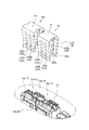
本実施形態の嵌合コネクタは、互いに嵌合接続される第1コネクタ1と第2コネクタ2とを備える(図1から図7)。ここで例示する嵌合コネクタは、第1コネクタ1と第2コネクタ2とが挿抜自在に構成されたものであり、第2コネクタ2が第1コネクタ1の電気回路の接続と切断を担っている。
The fitting connector of the present embodiment includes a
ここで、第1コネクタ1は、機器(図示略)の電気回路上に設けられる。その機器とは、例えば、車両の駆動装置(電気自動車又はハイブリッド車両の電動機やインバータ等)のことである。この第1コネクタ1は、第2コネクタ2が完全嵌合状態のときに機器の電気回路を接続し、第2コネクタ2が完全嵌合状態ではないときに機器の電気回路を切断する。
Here, the
第1コネクタ1は、第1ハウジング10と第1端子金具20とを備える(図1から図7)。一方、第2コネクタ2は、第2ハウジング110と第2端子金具120とを備える(図2、図3、図5及び図7)。
The
第1ハウジング10と第2ハウジング110は、合成樹脂等の絶縁性材料で成形される。第1ハウジング10は、第1嵌合部11を有する(図1、図3から図5及び図7)。また、第2ハウジング110は、第2嵌合部111を有する(図1から図7)。その第1嵌合部11と第2嵌合部111は、コネクタ挿入方向に沿った嵌合挿入が可能で、かつ、コネクタ抜去方向に沿った抜き取りが可能な形状のものとして形成される。例えば、この第1嵌合部11と第2嵌合部111は、筒状に形成され、その筒軸方向がコネクタ挿抜方向(コネクタ挿入方向、コネクタ抜去方向)となって互いに抜き差しされる。ここで示す第1嵌合部11は、筒軸方向における一旦を閉塞壁で閉塞させた筒状に形成されている。一方、ここで示す第2嵌合部111は、筒軸方向における両端を開口させた筒状に形成されている。また、ここで示す第1嵌合部11と第2嵌合部111は、筒軸方向に対する直交断面が長円の環状の筒体として形成されている。
The
第1端子金具20と第2端子金具120は、金属等の導電性材料で成形される。例えば、この第1端子金具20と第2端子金具120は、母材となる金属板に対する折曲げ加工や切断加工等のプレス成形によって所定形状に成形される。 The first terminal fitting 20 and the second terminal fitting 120 are formed of a conductive material such as metal. For example, the first terminal fitting 20 and the second terminal fitting 120 are formed into a predetermined shape by press molding such as bending or cutting on a metal plate as a base material.
第1端子金具20は、第1ハウジング10の第1嵌合部11の内方に収容される(図1及び図3)。ここで示す第1嵌合部11の中には、2つの第1端子金具20が収容されている。また、第2端子金具120は、第2ハウジング110の第2嵌合部111の内方に収容される(図2及び図3)。ここで示す第2嵌合部111の中には、2つの第2端子金具120が収容されている。この嵌合コネクタにおいては、それぞれの第1端子金具20を2つの第2端子金具120で電気接続させる。
The first terminal fitting 20 is housed inside the first
第1端子金具20は、平板状の被固定体21と、この被固定体21に対して直交配置された矩形の平板から成る雄タブ状の電気接続体22と、を有する(図1、図3、図5及び図7から図9)。被固定体21は、第1ハウジング10に対して第1端子金具20を固定するための部位である。第1端子金具20においては、その被固定体21が第1ハウジング10に対して螺子止め等で固定される。電気接続体22は、第2端子金具120に対して物理的且つ電気的に接続させるための部位である。
The first terminal fitting 20 has a flat plate-shaped
第1嵌合部11の中では、それぞれの第1端子金具20の電気接続体22における一方の平面同士が間隔を空けて対向配置されている(図1、図3、図5、図7及び図8)。第1ハウジング10は、その2つの電気接続体22の隙間に介在させる平板状の仕切り壁12を有している(図2、図3、図5、図7及び図9)。
In the first
また、それぞれの電気接続体22においては、他方の平面に電気接点部22aが膨出状態で設けられている(図8)。その電気接点部22aは、第2端子金具120の後述する電気接点部122a毎に設けられる。
Further, in each
第2端子金具120は、基体121と、この基体121に対して交差状態で配置して、自由端側の電気接点部122aを同一方向に向けてコネクタ挿入方向に対する直交方向に複数並べた片持ち形状の弾性接続体122と、を有する(図3、図5及び図7から図9)。その弾性接続体122は、電気接点部122aを第1端子金具20の電気接点部22aから引き離す開き方向への弾性変形が可能で、かつ、電気接点部122aを第1端子金具20の電気接点部22aに近づける開き方向とは逆方向への弾性変形が可能なものとして形成される。ここで示す第2端子金具120において、全ての弾性接続体122は、弾性変形量が同じ場合、それぞれが同じ大きさのバネ力を発生させるものとして形成されている。
The second terminal fitting 120 is cantilevered by arranging the
ここで示す第2端子金具120は、その1列に並べられた複数の弾性接続体122の組み合わせを2組有するものとして形成されている(図8及び図9)。この第2端子金具120においては、矩形の平板状の基体121における同一方向に延在させた2つの辺部から各々複数の弾性接続体122の組み合わせを突出させ、その2つの組み合わせにおけるそれぞれの弾性接続体122の電気接点部122aを互いに間隔を空けて対向配置させる。つまり、この第2端子金具120は、所謂クリップ形状の端子金具として形成されている。よって、この第2端子金具120は、一方の複数の弾性接続体122の組み合わせと他方の複数の弾性接続体122の組み合わせの間に、2つの第1端子金具20の電気接続体22を嵌入させる。これにより、この第2端子金具120は、全ての弾性接続体122が開き方向に弾性変形し、その弾性変形に伴う反力でそれぞれの電気接続体22を他方の平面側から挟み込んで、それぞれの電気接続体22に対して嵌合接続させる。従って、この第2端子金具120は、一方の複数の弾性接続体122の組み合わせが一方の電気接続体22に電気接続され、かつ、他方の複数の弾性接続体122の組み合わせが他方の電気接続体22に電気接続されて、2つの第1端子金具20を電気接続させる。
The second terminal fitting 120 shown here is formed as having two sets of a plurality of elastic connecting
尚、第2端子金具120は、嵌合コネクタが第1コネクタ1側の機器と第2コネクタ2側の機器とを電気接続させるものである場合、1列に並べられた複数の弾性接続体122の組み合わせを1組だけ有するものであってもよい。この場合の第2端子金具120は、図示しないが、矩形の平板状の基体121における同一方向に延在させた2つの辺部の内の一方から複数の弾性接続体122の組み合わせを突出させ、かつ、その2つの辺部の内の他方から平板状の壁体を突出させ、その壁体の平面と複数の弾性接続体122の組み合わせにおけるそれぞれの電気接点部122aとを間隔を空けて対向配置させる。つまり、この場合にも、第2端子金具120は、所謂クリップ形状の端子金具として形成されている。
In the second terminal fitting 120, when the fitting connector electrically connects the device on the
この嵌合コネクタにおいては、第1嵌合部11と第2嵌合部111とを規定の嵌合位置までコネクタ挿入方向に嵌合挿入していくことによって、この第1嵌合部11と第2嵌合部111が完全嵌合状態となり、このときに第1端子金具20と第2端子金具120とを電気接続させる。また、この嵌合コネクタにおいては、第1嵌合部11と第2嵌合部111とが規定の嵌合位置まで嵌め込まれていない分離状態又は半嵌合状態のときに、第1端子金具20と第2端子金具120とを電気接続させない。ここで示す嵌合コネクタにおいては、第1嵌合部11と第2嵌合部111が完全嵌合状態のときに、それぞれの第1端子金具20を第2端子金具120が電気接続させることによって、機器における分断された電気回路を接続状態にする。また、ここで示す嵌合コネクタにおいては、第1嵌合部11と第2嵌合部111が完全嵌合状態ではないとき(分離状態又は半嵌合状態のとき)に、それぞれの第1端子金具20を第2端子金具120が電気接続させないことによって、機器の電気回路を切断状態にする。
In this fitting connector, the first
この嵌合コネクタにおいては、第1コネクタ1と第2コネクタ2を嵌合接続させる際に、第1嵌合部11と第2嵌合部111をそれぞれの筒軸方向における開口側の先端同士を嵌め合わせた仮嵌合状態(半嵌合状態の一形態)とし(図4及び図5)、この第1嵌合部11と第2嵌合部111を仮嵌合状態から完全嵌合状態に移行させる(図6及び図7)。この嵌合コネクタは、第1嵌合部11と第2嵌合部111を仮嵌合状態から完全嵌合状態へと移行させる際の作業者の嵌合操作力を軽減させるべく、操作補助部材50に対する操作力に応じた嵌合挿入力を第1嵌合部11と第2嵌合部111との間に発生させ、第1嵌合部11と第2嵌合部111を仮嵌合状態から完全嵌合状態へとコネクタ挿入方向に沿って相対移動させる操作力補助機構3を備えている(図1から図7及び図10)。
In this fitting connector, when the
この操作力補助機構3は、例えば、操作補助部材50としてのレバー部材を第1嵌合部11と第2嵌合部111に対して回転操作させ、その回転操作力に応じた嵌合挿入力を第1嵌合部11と第2嵌合部111との間に発生させるものであってもよい。また、この操作力補助機構3は、例えば、操作補助部材50としての螺子部材の軸力を第1嵌合部11と第2嵌合部111との間に作用させるべく、その螺子部材を第1嵌合部11と第2嵌合部111に対して軸周りに回転操作させることによって、その回転操作力に応じた嵌合挿入力を第1嵌合部11と第2嵌合部111との間に発生させるものであってもよい。
The operating
ここで示す操作力補助機構3は、操作補助部材50としてレバー部材を用いている。よって、この嵌合コネクタにおいては、第1コネクタ1と第2コネクタ2を嵌合接続させる際に、第1嵌合部11と第2嵌合部111を仮嵌合状態とし、この仮嵌合状態で操作補助部材50が回転操作されることによって、第1嵌合部11と第2嵌合部111とが規定の嵌合位置まで深く嵌め込まれた完全嵌合状態になる。一方、この嵌合コネクタにおいては、第1コネクタ1と第2コネクタ2を切り離す際に、第1嵌合部11と第2嵌合部111とが完全嵌合状態のときに操作補助部材50が逆向きに回転操作されることによって、第1嵌合部11と第2嵌合部111とを仮嵌合状態に変位させる。この嵌合コネクタにおいては、この仮嵌合状態のときに第1嵌合部11と第2嵌合部111とを脱離させることが可能な脱離可能状態にもなっており、第1嵌合部11と第2嵌合部111とを引き離すことによって、第1コネクタ1と第2コネクタ2を分離させる。
The operating
操作補助部材50は、合成樹脂等の絶縁性材料で成形される。この操作補助部材50は、第2コネクタ2に設ける。この操作補助部材50は、第2ハウジング110に対する相対回転が可能な部材であり、その相対回転の回転方向に応じたコネクタ挿入方向の力(嵌合挿入力)又はコネクタ抜去方向の力(抜去力)を第1嵌合部11と第2嵌合部111との間に作用させる。よって、この操作補助部材50は、少なくとも第2ハウジング110が仮嵌合状態のときの仮嵌合位置(図4及び図5)と第2ハウジング110が完全嵌合状態のときの完全嵌合位置(図6及び図7)との間で、第2ハウジング110に対して相対回転させる。この操作補助部材50は、仮嵌合位置から完全嵌合位置に向けた第1回転操作で第2ハウジング110を仮嵌合状態から完全嵌合状態へと第1嵌合部11に対して相対移動させ、第1嵌合部11と第2嵌合部111とを完全嵌合させる。また、この操作補助部材50は、完全嵌合位置から仮嵌合位置に向けた第2回転操作で第2ハウジング110を完全嵌合状態から仮嵌合状態へと第1嵌合部11に対して相対移動させ、第1嵌合部11と第2嵌合部111の完全嵌合状態を解消させる。
The
ここで示す操作補助部材50は、第1回転操作及び第2回転操作の回動支点を有し、かつ、第1回転操作及び第2回転操作の回動軸の軸線方向で互いに間隔を空けて対向配置させた2本のアーム51,51と、2本のアーム51,51を連結させ、かつ、第1回転操作及び第2回転操作の力点となる操作部52と、を有する(図1、図2、図4及び図6)。
The
ここで示す操作補助部材50においては、その2本のアーム51,51の間に第2嵌合部111が配置され、それぞれのアーム51,51が第2嵌合部111に対して回動自在に取り付けられる。また、ここで示す操作補助部材50は、仮嵌合位置のときに、それぞれのアーム51,51の延在方向をコネクタ挿抜方向に向かせ、かつ、操作部52を第2嵌合部111の閉塞壁に対して間隔を空けて対向配置させる(図4)。また、ここで示す操作補助部材50は、完全嵌合位置のときに、それぞれのアーム51,51の延在方向をコネクタ挿抜方向に対する直交方向に向かせ、かつ、操作部52を第2嵌合部111の外周面に対向配置させる(図6)。
In the
アーム51は、操作部52側を固定端とする片持ち形状に形成され、その固定端と自由端51aとの間に回動支点が設けられる(図1、図2、図4及び図10)。ここで示すアーム51においては、円形の貫通孔を有する軸受51bが回動支点として形成されている(図1、図2、図4及び図10)。第2嵌合部111の外周面には、その軸受51bの貫通孔に挿入されて当該軸受51bに軸支される回動軸112がアーム51毎に突出状態で設けられている(図1、図2、図4及び図10)。
The
第1ハウジング10は、この操作補助部材50の第1回転操作の最中に、この操作補助部材50の自由端51aからコネクタ抜去方向に向けた力を受ける第1受け部10aを有している(図1、図3、図4、図6及び図10)。操作補助部材50は、そのコネクタ抜去方向に向けた力を第1受け部10aに作用させることによって、この第1受け部10aから反力を受ける。そこで、第2ハウジング110には、操作補助部材50の第1回転操作の最中に、第1受け部10aからの反力を受けた操作補助部材50の回動支点から力を受けて、コネクタ挿入方向に向けた力を第2嵌合部111に発生させる第2受け部110aが設けられている(図1、図2、図4及び図10)。これにより、この嵌合コネクタにおいては、操作補助部材50を第1回転操作することによって、仮嵌合状態の第1嵌合部11と第2嵌合部111とが規定の嵌合位置まで嵌め込まれて完全嵌合状態になる。つまり、この嵌合コネクタは、第1嵌合部11と第2嵌合部111を仮嵌合状態から完全嵌合状態に移行させる際の作業者の嵌合操作力を軽減させることができる。ここで示す第2受け部110aは、回動軸112であり(図1、図2、図4及び図10)、第1受け部10aからの反力に応じた力が軸受51bの貫通孔の内周壁から加えられる。
The
また、第1ハウジング10は、操作補助部材50の第2回転操作の最中に、この操作補助部材50の自由端51aからコネクタ挿入方向に向けた力を受ける第3受け部10bを有している(図3及び図10)。その第3受け部10bは、第1受け部10a対して間隔を空けて対向配置されている。操作補助部材50は、そのコネクタ挿入方向に向けた力を第3受け部10bに作用させることによって、この第3受け部10bから反力を受ける。そこで、第2ハウジング110には、操作補助部材50の第2回転操作の最中に、第3受け部10bからの反力を受けた操作補助部材50の回動支点から力を受けて、コネクタ抜去方向に向けた力を第2嵌合部111に発生させる第4受け部110bが設けられている(図1、図2、図4及び図10)。これにより、この嵌合コネクタにおいては、操作補助部材50を第2回転操作することによって、完全嵌合状態の第1嵌合部11と第2嵌合部111の嵌合代が減っていって仮嵌合状態になる。つまり、この嵌合コネクタは、第1嵌合部11と第2嵌合部111を完全嵌合状態から仮嵌合状態に移行させる際の作業者の抜去操作力を軽減させることができる。ここで示す第4受け部110bは、第2受け部110aと同じ回動軸112であり(図1、図2、図4及び図10)、第3受け部10bからの反力に応じた力が軸受51bの貫通孔の内周壁から加えられる。
Further, the
このように、本実施形態の嵌合コネクタにおいては、第1コネクタ1と第2コネクタ2を嵌合接続させる際に、先ず、第1嵌合部11と第2嵌合部111の先端同士を嵌め合わせた仮嵌合状態とする。続いて、本実施形態の嵌合コネクタにおいては、操作補助部材50を第1回転操作して、その仮嵌合状態の第1嵌合部11と第2嵌合部111に嵌合挿入力を作用させ、第1嵌合部11と第2嵌合部111を仮嵌合状態から完全嵌合状態に移行させる。従って、この嵌合コネクタにおいては、第1嵌合部11と第2嵌合部111が仮嵌合状態に正しく配置されていなければ、先に示したように、第1嵌合部11と第2嵌合部111を完全嵌合状態にまで嵌合挿入させることができなかったり、第1嵌合部11と第2嵌合部111の間や第1端子金具20と第2端子金具120との間に過荷重を発生させたりしてしまう可能性がある。
As described above, in the fitting connector of the present embodiment, when the
そこで、本実施形態の嵌合コネクタにおいては、第1嵌合部11と第2嵌合部111が仮嵌合状態であるのか否かを作業者が容易に識別できるように構成する。本実施形態の嵌合コネクタにおいては、第1嵌合部11と第2嵌合部111の先端同士を仮嵌合状態になるまで嵌め合わせる際に、第1コネクタ1と第2コネクタ2の間の嵌合挿入力を変化させることによって、第1嵌合部11と第2嵌合部111が仮嵌合状態であるのか否かを作業者に識別させる。
Therefore, the fitting connector of the present embodiment is configured so that the operator can easily identify whether or not the first
具体的に、本実施形態の嵌合コネクタにおいては、第2端子金具120における複数の弾性接続体122について、第1嵌合部11と第2嵌合部111が仮嵌合状態になるまでの間、開き方向の弾性変形によって基準バネ力を発生させるもの(以下、「基準弾性接続体」という。)122Aと、開き方向の弾性変形によって基準バネ力よりも大きな高圧バネ力を発生させるもの(以下、「高圧弾性接続体」という。)122Bと、に大別させる(図5、図8、図9及び図11)。そして、第1ハウジング10には、第1嵌合部11と第2嵌合部111を仮嵌合状態とする際に、基準弾性接続体122Aを開き方向に弾性変形させながら乗り越えさせる突出体(以下、「基準突出体」という。)13と、高圧弾性接続体122Bを開き方向に弾性変形させながら乗り越えさせる突出体(以下、「高圧突出体」という。)14と、を設ける(図1、図3、図5、図7、図9及び図11)。
Specifically, in the fitting connector of the present embodiment, for the plurality of elastic connecting
基準突出体13と高圧突出体14は、第1端子金具20の電気接続体22におけるコネクタ抜去方向側の端面よりもコネクタ抜去方向側に設ける(図3、図5及び図7)。ここで示す基準突出体13と高圧突出体14は、仕切り壁12におけるコネクタ抜去方向側の端面に突出状態で設けている。また、基準突出体13と高圧突出体14は、第1ハウジング10の突出基準面12aから突出させる(図3、図5、図7及び図11)。ここでは、仕切り壁12におけるそれぞれの平面(電気接続体22の一方の平面に対向配置される部分)を突出基準面12aとする。
The
基準突出体13は、基準弾性接続体122A毎に1つずつ設けてもよく、複数の弾性接続体122の組み合わせにて複数の基準弾性接続体122Aが連なっているのであれば、その複数の基準弾性接続体122Aに対応する1つを設けてもよい。これと同じように、高圧突出体14は、高圧弾性接続体122B毎に1つずつ設けてもよく、複数の弾性接続体122の組み合わせにて複数の高圧弾性接続体122Bが連なっているのであれば、その複数の高圧弾性接続体122Bに対応する1つを設けてもよい。この例示の第2端子金具120においては、複数の弾性接続体122の組み合わせにて、隣り合う2つの基準弾性接続体122Aが設定され、かつ、1つの高圧弾性接続体122Bが設定されている。また、この例示の第1ハウジング10においては、その隣り合う2つの基準弾性接続体122Aに対応させた1つの基準突出体13と、その1つの高圧弾性接続体122Bに対応させた1つの高圧突出体14と、が複数の弾性接続体122の組み合わせ毎で且つ第2端子金具120毎に形成されている。
The
基準突出体13は、仮嵌合状態に向けた第1嵌合部11及び第2嵌合部111の嵌合挿入に伴い基準弾性接続体122Aの自由端側を摺動させながら基準弾性接続体122Aを開き方向に弾性変形させ、第1嵌合部11及び第2嵌合部111が仮嵌合状態となったときに基準弾性接続体122Aの電気接点部122aを乗り越えさせるものとして形成される(図3→図5)。この基準突出体13は、基準弾性接続体122Aの自由端側を摺動させる摺動面(以下、「基準摺動面」という。)13aと、コネクタ挿入方向側で基準摺動面13aを突出基準面12aに繋ぐ端面(以下、「連結端面」という。)13bと、を有する(図11)。ここで示す連結端面13bは、突出基準面12aから垂設されている。
The
高圧突出体14は、仮嵌合状態に向けた第1嵌合部11及び第2嵌合部111の嵌合挿入に伴い高圧弾性接続体122Bの自由端側を摺動させながら高圧弾性接続体122Bを基準弾性接続体122Aよりも開き方向に大きく弾性変形させ、第1嵌合部11及び第2嵌合部111が仮嵌合状態となったときに高圧弾性接続体122Bの電気接点部122aを乗り越えさせ且つ高圧弾性接続体122Bを基準弾性接続体122Aと同じ位置まで開き方向とは逆向きに戻させるものとして形成される(図3→図5)。この高圧突出体14は、高圧弾性接続体122Bの自由端側を摺動させる摺動面(以下、「高圧摺動面」という。)14aと、コネクタ挿入方向側で高圧摺動面14aを突出基準面12aに繋ぐ端面(以下、「連結端面」という。)14bと、を有する(図11)。ここで示す連結端面14bは、突出基準面12aから垂設されている。
The high-
基準突出体13と高圧突出体14は、第1嵌合部11と第2嵌合部111の嵌合挿入が進むほど開き方向への弾性変形量が大きくなるものとして形成される。よって、基準摺動面13aは、基準弾性接続体122Aを開き方向に最も大きく弾性変形させる基準高圧部13a1を連結端面13bとの境界に有している(図11)。これと同じように、高圧摺動面14aは、高圧弾性接続体122Bを開き方向に最も大きく弾性変形させる高圧部14a1を連結端面14bとの境界に有している(図11)。例えば、基準摺動面13aと高圧摺動面14aは、コネクタ挿入方向側ほど突出基準面12aから大きく突出させた1つ若しくは複数の傾斜面(図11)、又は、コネクタ挿入方向に向かうに連れて突出基準面12aから徐々に大きく突出させた弧状面として形成される(図12)。
The
この嵌合コネクタにおいては、第1嵌合部11と第2嵌合部111の先端同士を嵌め合わせた仮嵌合状態とする際に、基準弾性接続体122Aが基準突出体13に沿って開き方向に弾性変形させられながら摺動され、かつ、高圧弾性接続体122Bが高圧突出体14に沿って開き方向に弾性変形させられながら摺動されていく。そして、この嵌合コネクタにおいては、第1嵌合部11と第2嵌合部111が仮嵌合状態となるときに、基準弾性接続体122Aの電気接点部122aが基準突出体13を乗り越え、かつ、高圧弾性接続体122Bの電気接点部122aが高圧突出体14を乗り越える。基準弾性接続体122Aは、その乗り越えの際、開き方向の弾性変形に伴う反力によって弾性変形量が小さくなっていき、基準突出体13を乗り越えるときよりも小さな弾性変形量で開き方向に弾性変形している状態又は弾性変形前の元の形状の状態に変位する。また、高圧弾性接続体122Bは、その乗り越えの際、開き方向の弾性変形に伴う反力によって弾性変形量が小さくなっていき、基準弾性接続体122Aと同じ位置へと変位する。
In this fitting connector, the reference elastic connecting
このように、この嵌合コネクタにおいては、第1嵌合部11と第2嵌合部111の先端同士を嵌め合わせた仮嵌合状態とする際に、基準弾性接続体122Aと基準突出体13の組み合わせしか存在していない場合と比較して、高圧弾性接続体122Bと高圧突出体14の組み合わせの存在によって挿入抵抗を高めていくことができる。よって、この嵌合コネクタは、その挿入抵抗を作業者に感じ取らせることができる。そして、この嵌合コネクタにおいては、第1嵌合部11と第2嵌合部111が仮嵌合状態となるときに、基準弾性接続体122Aと基準突出体13の組み合わせしか存在していない場合と比較して、高圧弾性接続体122Bと高圧突出体14の組み合わせの存在によって挿入抵抗の減少量が大きくなる。よって、この嵌合コネクタは、挿入抵抗が減ったときの抜け感を作業者に感じ取らせることができる。従って、本実施形態の嵌合コネクタは、第1嵌合部11と第2嵌合部111が仮嵌合状態であるのか否かを作業者に容易に識別させることができる。
As described above, in this fitting connector, the reference elastic connecting
この嵌合コネクタにおいては、高圧弾性接続体122Bの電気接点部122aが高圧突出体14を乗り越えたときに、この高圧弾性接続体122Bの自由端側を例えば電気接続体22に当接させてもよい。この場合、高圧弾性接続体122Bの自由端側は、電気接続体22に当接したときに打音を発生させる。従って、この場合の嵌合コネクタは、その高圧弾性接続体122Bの電気接点部122aが高圧突出体14を乗り越えたときの打音によって、第1嵌合部11と第2嵌合部111が仮嵌合状態であるのか否かを作業者に容易に識別させることができる。
In this mating connector, even if the free end side of the high-voltage
ここで、この嵌合コネクタにおいては、基準弾性接続体122Aと基準突出体13の組み合わせを無くして、高圧弾性接続体122Bと高圧突出体14の組み合わせだけで構成してもよい。これによれば、この嵌合コネクタは、上記の例示と比較して、高圧弾性接続体122Bの電気接点部122aが高圧突出体14を乗り越えるまでの挿入抵抗が大きくなるので、電気接点部122aが高圧突出体14を乗り越えたときの挿入抵抗の減少量が大きくなり、その際の抜け感をより大きく作業者に感じ取らせることができる。従って、この嵌合コネクタは、第1嵌合部11と第2嵌合部111が仮嵌合状態であるのか否かの識別性が高くなる。しかしながら、この嵌合コネクタは、その挿入抵抗が過大になってしまうと、第1嵌合部11と第2嵌合部111を仮嵌合状態とする際の作業性を低下させてしまう可能性がある。そこで、本実施形態の嵌合コネクタにおいては、上記の例示の如く、基準弾性接続体122A及び基準突出体13の組み合わせと高圧弾性接続体122B及びと高圧突出体14の組み合わせを混在させることによって、挿入抵抗が過大とならぬようその適正化を図ることができる。
Here, in this fitting connector, the combination of the reference
また、この嵌合コネクタにおいては、突出基準面12aに対する高圧摺動面14aの突出量を変えるなど、高圧摺動面14aの形状を調整するだけで、第1嵌合部11と第2嵌合部111を仮嵌合状態とする際の挿入抵抗を調整することができる。従って、この嵌合コネクタは、第1嵌合部11と第2嵌合部111が仮嵌合状態であるのか否かを簡易的な構造で作業者に容易に識別させることができる。
Further, in this fitting connector, the first
ところで、従来、この種の嵌合コネクタにおいては、2つのコネクタ間を嵌合接続させる際の端子同士のど突きを防ぐべく、一方の端子金具の先端よりも突出させたど突き防止部を一方のハウジングに設けることがある。よって、嵌合コネクタにおいては、そのど突き防止部に上記の基準突出体13と高圧突出体14を設けてもよく、上記の基準突出体13と高圧突出体14をど突き防止部としても利用できるようにしてもよい。
By the way, conventionally, in this type of mating connector, in order to prevent the terminals from sticking to each other when mating and connecting the two connectors, one of the sticking prevention portions is projected from the tip of one of the terminal fittings. May be installed in the housing. Therefore, in the mating connector, the
1 第1コネクタ
2 第2コネクタ
3 操作力補助機構
10 第1ハウジング
11 第1嵌合部
12a 突出基準面
13 基準突出体
14 高圧突出体
14a 高圧摺動面
14a1 高圧部
14b 連結端面
20 第1端子金具
50 操作補助部材
110 第2ハウジング
111 第2嵌合部
120 第2端子金具
121 基体
122 弾性接続体
122A 基準弾性接続体
122B 高圧弾性接続体
122a 電気接点部
1
Claims (4)
コネクタ挿入方向に沿った前記第1嵌合部との間での嵌合挿入が可能な第2嵌合部を有する第2ハウジング、並びに、前記第2ハウジングに収容され、前記第1嵌合部及び前記第2嵌合部が完全嵌合状態のときに前記第1端子金具に対して電気接続される第2端子金具を備える第2コネクタと、
操作補助部材に対する操作力に応じた嵌合挿入力を前記第1嵌合部と前記第2嵌合部との間に発生させ、前記第1嵌合部と前記第2嵌合部を仮嵌合状態から前記完全嵌合状態へと前記コネクタ挿入方向に沿って相対移動させる操作力補助機構と、
を備え、
前記第2端子金具は、基体と、前記基体に対して交差状態で配置して、自由端側の電気接点部を同一方向に向けて前記コネクタ挿入方向に対する直交方向に複数並べた片持ち形状で、前記電気接点部を前記第1端子金具から引き離す開き方向への弾性変形が可能な弾性接続体と、を有し、
前記第1ハウジングは、前記仮嵌合状態に向けた前記第1嵌合部及び前記第2嵌合部の嵌合挿入に伴い複数の前記弾性接続体の内の基準弾性接続体の前記自由端側を摺動させながら前記基準弾性接続体を前記開き方向に弾性変形させ、前記第1嵌合部及び前記第2嵌合部が前記仮嵌合状態となったときに前記基準弾性接続体の前記電気接点部を乗り越えさせる基準突出体と、前記仮嵌合状態に向けた前記第1嵌合部及び前記第2嵌合部の嵌合挿入に伴い複数の前記弾性接続体の内の高圧弾性接続体の前記自由端側を摺動させながら前記高圧弾性接続体を前記基準弾性接続体よりも前記開き方向に大きく弾性変形させ、前記第1嵌合部及び前記第2嵌合部が前記仮嵌合状態となったときに前記高圧弾性接続体の前記電気接点部を乗り越えさせ且つ前記高圧弾性接続体を前記基準弾性接続体と同じ位置まで前記開き方向とは逆向きに戻させる高圧突出体と、を有することを特徴とした嵌合コネクタ。 A first housing having a first fitting portion, and a first connector having a first terminal fitting housed in the first housing.
A second housing having a second fitting portion capable of being fitted and inserted to and from the first fitting portion along the connector insertion direction, and the first fitting portion accommodated in the second housing. And a second connector provided with a second terminal fitting that is electrically connected to the first terminal fitting when the second fitting portion is in a completely fitted state.
A fitting insertion force corresponding to the operation force for the operation assisting member is generated between the first fitting portion and the second fitting portion, and the first fitting portion and the second fitting portion are temporarily fitted. An operating force assisting mechanism that relatively moves from the fitted state to the fully fitted state along the connector insertion direction,
Equipped with
The second terminal fitting has a cantilever shape in which the substrate and the substrate are arranged in an intersecting state, and a plurality of electrical contact portions on the free end side are arranged in the same direction and in a direction orthogonal to the connector insertion direction. With an elastic connector capable of elastic deformation in the opening direction, which separates the electric contact portion from the first terminal fitting.
The first housing is the free end of the reference elastic connection among the plurality of elastic connections due to the fitting insertion of the first fitting portion and the second fitting portion toward the temporary fitting state. The reference elastic connection body is elastically deformed in the opening direction while sliding the side, and when the first fitting portion and the second fitting portion are in the temporary fitting state, the reference elastic connection body High-pressure elasticity among the plurality of elastic connectors due to the fitting insertion of the reference projecting body overcoming the electrical contact portion and the first fitting portion and the second fitting portion toward the temporary fitting state. While sliding the free end side of the connection body, the high-pressure elastic connection body is elastically deformed more in the opening direction than the reference elastic connection body, and the first fitting portion and the second fitting portion are provisionally described. A high-pressure projecting body that overcomes the electrical contact portion of the high-pressure elastic connection body and returns the high-pressure elastic connection body to the same position as the reference elastic connection body in the direction opposite to the opening direction when the mated state is reached. And, a mating connector characterized by having.
前記高圧突出体は、前記高圧弾性接続体の前記自由端側を摺動させる高圧摺動面と、前記コネクタ挿入方向側で前記高圧摺動面を前記突出基準面に繋ぐ連結端面と、を有し、
前記高圧摺動面は、前記高圧弾性接続体を前記開き方向に最も大きく弾性変形させる高圧部を前記連結端面との境界に有することを特徴とした請求項1に記載の嵌合コネクタ。 The reference projecting body and the high-pressure projecting body are projected from the projecting reference surface of the first housing.
The high-pressure projecting body has a high-pressure sliding surface that slides the free end side of the high-pressure elastic connection body, and a connecting end surface that connects the high-pressure sliding surface to the projecting reference surface on the connector insertion direction side. death,
The fitting connector according to claim 1, wherein the high-pressure sliding surface has a high-pressure portion that elastically deforms the high-pressure elastic connector in the opening direction at the boundary with the connecting end surface.
Priority Applications (4)
| Application Number | Priority Date | Filing Date | Title |
|---|---|---|---|
| JP2020077008A JP7091008B2 (en) | 2020-04-24 | 2020-04-24 | Mating connector |
| US17/226,478 US11404822B2 (en) | 2020-04-24 | 2021-04-09 | Fitting connector |
| EP21169130.8A EP3902070B1 (en) | 2020-04-24 | 2021-04-19 | Fitting connector |
| CN202110436276.4A CN113555745B (en) | 2020-04-24 | 2021-04-22 | Fitting connector |
Applications Claiming Priority (1)
| Application Number | Priority Date | Filing Date | Title |
|---|---|---|---|
| JP2020077008A JP7091008B2 (en) | 2020-04-24 | 2020-04-24 | Mating connector |
Publications (2)
| Publication Number | Publication Date |
|---|---|
| JP2021174658A JP2021174658A (en) | 2021-11-01 |
| JP7091008B2 true JP7091008B2 (en) | 2022-06-27 |
Family
ID=75581458
Family Applications (1)
| Application Number | Title | Priority Date | Filing Date |
|---|---|---|---|
| JP2020077008A Active JP7091008B2 (en) | 2020-04-24 | 2020-04-24 | Mating connector |
Country Status (4)
| Country | Link |
|---|---|
| US (1) | US11404822B2 (en) |
| EP (1) | EP3902070B1 (en) |
| JP (1) | JP7091008B2 (en) |
| CN (1) | CN113555745B (en) |
Citations (9)
| Publication number | Priority date | Publication date | Assignee | Title |
|---|---|---|---|---|
| JP2002216593A (en) | 2001-01-23 | 2002-08-02 | Auto Network Gijutsu Kenkyusho:Kk | Breaker device |
| JP2008533684A (en) | 2005-03-15 | 2008-08-21 | タイコ・エレクトロニクス・コーポレイション | Lever fitting type connector assembly having connector position assurance device |
| JP2010146950A (en) | 2008-12-22 | 2010-07-01 | Sumitomo Wiring Syst Ltd | Lever-type connector |
| JP2018206718A (en) | 2017-06-09 | 2018-12-27 | 矢崎総業株式会社 | Connector device |
| JP2019220327A (en) | 2018-06-19 | 2019-12-26 | 矢崎総業株式会社 | Power supply circuit shut-off device |
| JP2020004513A (en) | 2018-06-26 | 2020-01-09 | タイコエレクトロニクスジャパン合同会社 | Electric connector |
| JP2020145040A (en) | 2019-03-05 | 2020-09-10 | 矢崎総業株式会社 | Power circuit breaker |
| JP2021057193A (en) | 2019-09-30 | 2021-04-08 | 矢崎総業株式会社 | Power supply circuit breaker |
| JP2021174657A (en) | 2020-04-24 | 2021-11-01 | 矢崎総業株式会社 | Lever-type connector |
Family Cites Families (25)
| Publication number | Priority date | Publication date | Assignee | Title |
|---|---|---|---|---|
| JP3007812U (en) * | 1994-05-25 | 1995-02-28 | モレックス インコーポレーテッド | Surface mount electrical connector |
| US5769650A (en) * | 1995-06-19 | 1998-06-23 | Sumitomo Wiring Systems, Ltd. | Connector and cover therefor |
| JP3567856B2 (en) * | 2000-06-08 | 2004-09-22 | 住友電装株式会社 | Connector support structure |
| JP2002237340A (en) * | 2001-02-09 | 2002-08-23 | Yamaichi Electronics Co Ltd | Card edge connector |
| JP2005216526A (en) * | 2004-01-27 | 2005-08-11 | Smk Corp | Connector |
| US7258585B2 (en) * | 2005-01-13 | 2007-08-21 | Cooper Technologies Company | Device and method for latching separable insulated connectors |
| JP2008108560A (en) * | 2006-10-25 | 2008-05-08 | Iriso Denshi Kogyo Kk | Connector |
| KR100858755B1 (en) * | 2006-11-20 | 2008-09-16 | 에프씨아이 커넥터즈 싱가포르 피티이 엘티디. | Electrical connector and connector assembly |
| JP4374074B1 (en) * | 2009-06-10 | 2009-12-02 | イリソ電子工業株式会社 | Electrical connection terminal and connector using the same |
| CN201918521U (en) * | 2010-11-05 | 2011-08-03 | 庆良电子股份有限公司 | Power connector assembly |
| JP6099203B2 (en) * | 2013-09-03 | 2017-03-22 | 日本航空電子工業株式会社 | Connector device |
| CN104425919B (en) * | 2013-09-05 | 2018-06-08 | 意力速电子工业株式会社 | Connector |
| JP6119671B2 (en) * | 2014-05-27 | 2017-04-26 | 住友電装株式会社 | connector |
| CN204349085U (en) * | 2014-10-10 | 2015-05-20 | 康普技术有限责任公司 | A kind of blind low intermodulation radio frequency connector assembly of joining float type |
| US10044115B2 (en) * | 2015-12-23 | 2018-08-07 | Intel Corporation | Universal linear edge connector |
| JP6446392B2 (en) * | 2016-05-23 | 2018-12-26 | ヒロセ電機株式会社 | Connection structure between circuit board electrical connector and mating connection member |
| CN206595424U (en) * | 2016-10-05 | 2017-10-27 | 番禺得意精密电子工业有限公司 | Connector |
| JP6720061B2 (en) * | 2016-11-18 | 2020-07-08 | 日本航空電子工業株式会社 | Connector device |
| JP6865103B2 (en) * | 2017-05-25 | 2021-04-28 | 矢崎総業株式会社 | Lever type connector |
| JP7032094B2 (en) * | 2017-10-06 | 2022-03-08 | 京セラ株式会社 | Connectors and electronic devices |
| US10476191B2 (en) * | 2018-02-28 | 2019-11-12 | Ohio Associated Enterprises, Llc | Forked electrical contact pair with elastic tail |
| JP6582082B2 (en) * | 2018-03-09 | 2019-09-25 | 京セラ株式会社 | Connectors and electronic devices |
| JP7109303B2 (en) * | 2018-08-07 | 2022-07-29 | 日本航空電子工業株式会社 | connector assembly |
| CN109066152A (en) * | 2018-08-24 | 2018-12-21 | 郑州云海信息技术有限公司 | A kind of connector |
| US10971850B2 (en) * | 2018-10-23 | 2021-04-06 | Iriso Electronics Co., Ltd. | Movable connector |
-
2020
- 2020-04-24 JP JP2020077008A patent/JP7091008B2/en active Active
-
2021
- 2021-04-09 US US17/226,478 patent/US11404822B2/en active Active
- 2021-04-19 EP EP21169130.8A patent/EP3902070B1/en active Active
- 2021-04-22 CN CN202110436276.4A patent/CN113555745B/en active Active
Patent Citations (9)
| Publication number | Priority date | Publication date | Assignee | Title |
|---|---|---|---|---|
| JP2002216593A (en) | 2001-01-23 | 2002-08-02 | Auto Network Gijutsu Kenkyusho:Kk | Breaker device |
| JP2008533684A (en) | 2005-03-15 | 2008-08-21 | タイコ・エレクトロニクス・コーポレイション | Lever fitting type connector assembly having connector position assurance device |
| JP2010146950A (en) | 2008-12-22 | 2010-07-01 | Sumitomo Wiring Syst Ltd | Lever-type connector |
| JP2018206718A (en) | 2017-06-09 | 2018-12-27 | 矢崎総業株式会社 | Connector device |
| JP2019220327A (en) | 2018-06-19 | 2019-12-26 | 矢崎総業株式会社 | Power supply circuit shut-off device |
| JP2020004513A (en) | 2018-06-26 | 2020-01-09 | タイコエレクトロニクスジャパン合同会社 | Electric connector |
| JP2020145040A (en) | 2019-03-05 | 2020-09-10 | 矢崎総業株式会社 | Power circuit breaker |
| JP2021057193A (en) | 2019-09-30 | 2021-04-08 | 矢崎総業株式会社 | Power supply circuit breaker |
| JP2021174657A (en) | 2020-04-24 | 2021-11-01 | 矢崎総業株式会社 | Lever-type connector |
Also Published As
| Publication number | Publication date |
|---|---|
| JP2021174658A (en) | 2021-11-01 |
| EP3902070B1 (en) | 2022-06-08 |
| EP3902070A1 (en) | 2021-10-27 |
| US11404822B2 (en) | 2022-08-02 |
| CN113555745B (en) | 2023-02-24 |
| US20210336388A1 (en) | 2021-10-28 |
| CN113555745A (en) | 2021-10-26 |
Similar Documents
| Publication | Publication Date | Title |
|---|---|---|
| JP4272037B2 (en) | Lever fitting type power circuit breaker | |
| JP5129263B2 (en) | Electrical connectors and connector assemblies | |
| JPH11162567A (en) | Cable connector assembly component | |
| JP2924551B2 (en) | Terminal for connector | |
| JP6792424B2 (en) | Connector device | |
| JP4989285B2 (en) | Connector mating structure | |
| JP7091008B2 (en) | Mating connector | |
| JP3355161B2 (en) | Lever terminal | |
| JP2018195505A (en) | Connector device | |
| WO2012063598A1 (en) | Power source circuit cutoff device | |
| JP6793683B2 (en) | Lever type connector | |
| JP7174007B2 (en) | lever type connector | |
| JP2008262718A (en) | Connector | |
| WO2023157894A1 (en) | Connector | |
| JP3112228B2 (en) | Short circuit member for terminal | |
| JP2023156650A (en) | service plug | |
| JP2812124B2 (en) | Lever connector | |
| JP4234521B2 (en) | Power off connector | |
| JP4249606B2 (en) | Lever type connector | |
| JP3355480B2 (en) | ZIF connector | |
| CN104769789A (en) | Connector | |
| KR20240020015A (en) | Lever-type connector assembly | |
| JP2013025985A (en) | Electric connector and fitting method and releasing method of electric connector | |
| JPH08222320A (en) | Connector | |
| KR20090116086A (en) | Block type connector assembly for vehicle |
Legal Events
| Date | Code | Title | Description |
|---|---|---|---|
| A621 | Written request for application examination |
Free format text: JAPANESE INTERMEDIATE CODE: A621 Effective date: 20210716 |
|
| A977 | Report on retrieval |
Free format text: JAPANESE INTERMEDIATE CODE: A971007 Effective date: 20220518 |
|
| TRDD | Decision of grant or rejection written | ||
| A01 | Written decision to grant a patent or to grant a registration (utility model) |
Free format text: JAPANESE INTERMEDIATE CODE: A01 Effective date: 20220614 |
|
| A61 | First payment of annual fees (during grant procedure) |
Free format text: JAPANESE INTERMEDIATE CODE: A61 Effective date: 20220614 |
|
| R150 | Certificate of patent or registration of utility model |
Ref document number: 7091008 Country of ref document: JP Free format text: JAPANESE INTERMEDIATE CODE: R150 |
|
| S531 | Written request for registration of change of domicile |
Free format text: JAPANESE INTERMEDIATE CODE: R313531 |
|
| R350 | Written notification of registration of transfer |
Free format text: JAPANESE INTERMEDIATE CODE: R350 |