EP1947348A2 - Système de compression de carburant doté d'un réchauffement interne pour la suppression du point de rosée - Google Patents
Système de compression de carburant doté d'un réchauffement interne pour la suppression du point de rosée Download PDFInfo
- Publication number
- EP1947348A2 EP1947348A2 EP20070253470 EP07253470A EP1947348A2 EP 1947348 A2 EP1947348 A2 EP 1947348A2 EP 20070253470 EP20070253470 EP 20070253470 EP 07253470 A EP07253470 A EP 07253470A EP 1947348 A2 EP1947348 A2 EP 1947348A2
- Authority
- EP
- European Patent Office
- Prior art keywords
- gas
- hot
- airflow
- oil
- generate
- Prior art date
- Legal status (The legal status is an assumption and is not a legal conclusion. Google has not performed a legal analysis and makes no representation as to the accuracy of the status listed.)
- Withdrawn
Links
Images
Classifications
-
- F—MECHANICAL ENGINEERING; LIGHTING; HEATING; WEAPONS; BLASTING
- F04—POSITIVE - DISPLACEMENT MACHINES FOR LIQUIDS; PUMPS FOR LIQUIDS OR ELASTIC FLUIDS
- F04D—NON-POSITIVE-DISPLACEMENT PUMPS
- F04D29/00—Details, component parts, or accessories
- F04D29/58—Cooling; Heating; Diminishing heat transfer
- F04D29/582—Cooling; Heating; Diminishing heat transfer specially adapted for elastic fluid pumps
- F04D29/5826—Cooling at least part of the working fluid in a heat exchanger
-
- B—PERFORMING OPERATIONS; TRANSPORTING
- B01—PHYSICAL OR CHEMICAL PROCESSES OR APPARATUS IN GENERAL
- B01D—SEPARATION
- B01D53/00—Separation of gases or vapours; Recovering vapours of volatile solvents from gases; Chemical or biological purification of waste gases, e.g. engine exhaust gases, smoke, fumes, flue gases, aerosols
- B01D53/26—Drying gases or vapours
- B01D53/265—Drying gases or vapours by refrigeration (condensation)
-
- B—PERFORMING OPERATIONS; TRANSPORTING
- B01—PHYSICAL OR CHEMICAL PROCESSES OR APPARATUS IN GENERAL
- B01D—SEPARATION
- B01D2257/00—Components to be removed
- B01D2257/80—Water
Definitions
- the present invention relates to a fuel compression system with internal reheat for dew point suppression.
- the invention provides a system for conditioning a gas.
- the system includes a compressor for compressing and heating the gas into a hot gas; an airflow device generating an airflow; and a heat exchanger receiving in a first flow path the hot gas and in a second flow path the airflow.
- Heat is transferred from the hot gas to the airflow to generate a cool gas and hot airflow, and moisture condenses within the cool gas.
- a moisture separator separates condensed moisture from the cool gas to generate a saturated gas.
- a reheater receives in one flow path the saturated gas from the moisture separator and in another flow path the hot airflow from the heat exchanger. Heat is transferred in the reheater from the hot airflow to the saturated gas to generate a superheated gas having a temperature above the saturation temperature of the gas.
- the compressor may include an oil-flooded compressor, such that oil mixes with the hot gas.
- Such embodiments may include a separator for separating the oil from the hot gas, and may also include an oil cooler that exchanges heat from the oil to the airflow.
- the invention provides a method for conditioning gas, the method comprising: compressing and heating the gas in a compressor to generate a hot gas; generating an airflow; exchanging heat between the hot gas and the airflow to generate a cool gas and a hot airflow; separating moisture from the cool gas to generate a saturated gas; and reheating the cool gas with the hot airflow to generate a superheated gas.
- the invention provides a microturbine engine for generating electricity.
- the microturbine engine includes an air compressor, and a combustor that combusts a mixture of gas from a system for conditioning fuel as described above with compressed air from the air compressor.
- the combustor creates products of combustion.
- the microturbine engine further includes a power turbine rotating in response to expansion of the products of combustion.
- the turbine drives rotation of an electricity generator.
- the microturbine engine further includes a recuperator that exchanges heat from the products of combustion to the compressed air prior to the compressed air entering the combustor.
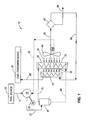
- Fig. 1 is a schematic illustration of one embodiment of a fuel compression system of the present invention.
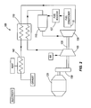
- Fig. 2 is a schematic illustration of a microturbine engine generator system for use with the present invention.
- Fig. 1 illustrates a fuel compression/conditioning system 10 that receives wet (i.e., containing water vapor) gas from a fuel source 20, removes condensed water from the gas, and delivers the gas to a fuel consuming device 30.
- the system 10 includes a compressor 35, a motor 40, a separator tank 45, an aftercooler 50, an oil cooler 55, a blower 60, a moisture separator 65, and a reheater 70.
- the fuel source 20 may be, for example, a waste water treatment facility, landfill, or other site from which gas is extracted.
- the impurities in the gas may be, for example, siloxanes or other contaminants that would cause pollution or damage to a combustion chamber and associated moving parts if not removed from the gas.
- the fuel consuming device 30 may be, for example, a flare that bums the gas to reduce the amount of unburned hydrocarbons that are released into the environment.
- the fuel consuming device may be an engine that uses the gas fuel for doing work. Examples of such engines include reciprocating engines, microturbine engines, and larger gas turbine engines. Examples of work done by such engines include production of electricity, driving chillers, refrigerators, or compressors, cogeneration of hot water, and raising, lowering, or otherwise moving objects.
- the compressor 35 may be, for example, an oil flooded screw compressor and is powered by the motor 40. Gas and oil mix in the compressor 35 while the pressure of the gas increases. The gas and oil become hot during compression. A flow of hot gas and oil flows out of the compressor (at 72) at a temperature of about 220°F in the illustrated embodiment.
- the flow of hot gas and oil then enters the separator tank 45, in which the gas rises to the top and the oil sinks to the bottom. From the separator tank 45, the gas is directed (at 75) to the aftercooler 50 and the oil is directed (at 80) to the oil cooler 55.
- Each of the aftercooler 50 and oil cooler 55 includes a first flow path for respective hot gas and hot oil.
- the aftercooler 50 and oil cooler 55 may take the form of any heat exchanger that provides the functionality describe herein, including, for example, counterflow or cross-flow plate-fin heat exchangers and tube-fin heat exchangers.
- the blower 60 blows relatively cool ambient air (at 81) through second flow paths in the aftercooler 50 and oil cooler 55 to cool the hot gas and hot oil.
- a fan or any other airflow device having the ability to move air across a heat exchanger may be used in place of the blower 60.
- the temperature of the air raises and a hot airflow (at 82) is generated.
- the gas temperature drops to about 15°F above ambient temperature
- the oil temperature drops to about 175°F, but in other embodiments the aftercooler 50 and oil cooler 55 may be sized to achieve other target temperatures.
- the gas may be termed a cool gas after exiting the aftercooler 50.
- the cool gas is directed to the moisture separator 65 (at 83) and the oil re-enters the compressor 35 (at 85) to be used again.
- the moisture separator 65 removes any water that may have condensed in the cool gas as a result of the drop in gas temperature across the aftercooler 50. Flowing out of the moisture separator 65 is gas that is still at a temperature of about 15°F above ambient, and is saturated (i.e., the gas is at its dew point). The saturated gas exits the moisture separator 65 (at 90) and enters one flow path in the reheater 70. Also flowing out of the moisture separator 65 (at 95) is water.
- the reheater 70 is positioned on the opposite side of the aftercooler 50 and oil cooler 55 from the blower 60 such that the hot airflow 82 (i.e., the air flowing out of the aftercooler 50 and oil cooler 55) flows through another flow path (i.e., a different flow path from the one through which the saturated gas is flowing) in the reheater 70.
- the reheater 70 may take the form of any heat exchanger that provides the functionality describe herein, including, for example, a counterflow or cross-flow plate-fin heat exchanger and tube-fin heat exchanger.
- the reheater 70 may be mounted on the aftercooler 50 and oil cooler 55, but in other embodiments it may be mounted separately.
- the reheater 70 heat is exchanged from the hot airflow to the saturated gas, such that the gas temperature raises above its dew point or saturation temperature.
- the gas may be termed "superheated" upon exiting (at 96) the reheater 70 because its temperature is raised above its saturation temperature.
- the reheater 70 is sized to generate the superheated gas 96 at a temperature of about 40°F above ambient temperature. This heating causes dew point suppression such that any remaining moisture becomes trapped in the gas and does not condense while the gas is being consumed in the fuel consuming device 30.
- Fig. 2 schematically illustrates one type of fuel consuming device that may be used in conjunction with the fuel conditioning system 10 described above.
- the illustrated fuel consuming device is a microturbine engine generator 100, which is useful in distributed power applications, and can even be mounted on skids and moved between job sites.
- Microturbine engine generators usually generate 2 MW of power or less, and are therefore relatively small when compared to power generators in power plants that are on the grid.
- the illustrated microturbine engine generator 100 includes a compressor 105, a recuperator 110, a combustor 115, a power turbine 120, and an electric power generator 125.
- Air is compressed in the compressor 105 and delivered to a cool side of the recuperator 110.
- the recuperator 110 may be, for example, a counterflow plate-fin type heat exchanger.
- the compressed air is preheated within the recuperator 110 and mixed with a gaseous fuel from a fuel supply (e.g., the superheated gas 96 from the fuel conditioning system 10 described above and illustrated in Fig. 1) to create a combustible mixture.
- the combustible mixture is combusted in the combustor 115 to create products of combustion.
- the products of combustion are then permitted to expand through the power turbine 120 to impart rotational energy to the power turbine 120.
- Rotation of the power turbine 120 drives operation of the electric generator 125 through an optional gearbox 130 to produce electrical power at a useful frequency.
- power electronics may be used in place of the gearbox 130 to condition the electrical signal into a useful frequency.
- the power turbine 120 and compressor 105 are coupled for rotation together via a shaft 135, so rotation of the power turbine 120 also drives rotation of the compressor 105.
- the power turbine 120 may only drive the power generator 125, and an additional gasifier turbine may be used to drive the compressor 105.
- the products of combustion are expanded through both the power turbine 120 and the gasifier turbine.
- the products of combustion Prior to exhausting the products of combustion from the microturbine engine 100, they flow into a hot side of the recuperator 110 to preheat the inflowing compressed air. Any remaining heat in the products of combustion is used for some other useful purpose (e.g., heating water) in a final heat exchanger 140 before the products of combustion are exhausted.
- a hot side of the recuperator 110 Prior to exhausting the products of combustion from the microturbine engine 100, they flow into a hot side of the recuperator 110 to preheat the inflowing compressed air. Any remaining heat in the products of combustion is used for some other useful purpose (e.g., heating water) in a final heat exchanger 140 before the products of combustion are exhausted.
Landscapes
- Engineering & Computer Science (AREA)
- Physics & Mathematics (AREA)
- Thermal Sciences (AREA)
- Chemical & Material Sciences (AREA)
- Oil, Petroleum & Natural Gas (AREA)
- General Chemical & Material Sciences (AREA)
- Analytical Chemistry (AREA)
- Chemical Kinetics & Catalysis (AREA)
- Mechanical Engineering (AREA)
- General Engineering & Computer Science (AREA)
- Drying Of Gases (AREA)
- Engine Equipment That Uses Special Cycles (AREA)
- Compressor (AREA)
Applications Claiming Priority (1)
| Application Number | Priority Date | Filing Date | Title |
|---|---|---|---|
| US11/552,182 US7753975B2 (en) | 2006-10-24 | 2006-10-24 | Fuel compression system with internal reheat for dew point suppression |
Publications (2)
| Publication Number | Publication Date |
|---|---|
| EP1947348A2 true EP1947348A2 (fr) | 2008-07-23 |
| EP1947348A3 EP1947348A3 (fr) | 2014-09-17 |
Family
ID=39156264
Family Applications (1)
| Application Number | Title | Priority Date | Filing Date |
|---|---|---|---|
| EP07253470.4A Withdrawn EP1947348A3 (fr) | 2006-10-24 | 2007-09-01 | Système de compression de carburant doté d'un réchauffement interne pour la suppression du point de rosée |
Country Status (4)
| Country | Link |
|---|---|
| US (1) | US7753975B2 (fr) |
| EP (1) | EP1947348A3 (fr) |
| CN (1) | CN101201016B (fr) |
| RU (1) | RU2467190C2 (fr) |
Cited By (2)
| Publication number | Priority date | Publication date | Assignee | Title |
|---|---|---|---|---|
| CN102996489A (zh) * | 2011-09-08 | 2013-03-27 | 中国石油化工股份有限公司 | 离心式天然气压缩机机组段间阻垢方法 |
| WO2024086484A1 (fr) * | 2022-10-19 | 2024-04-25 | Ge Infrastructure Technology Llc | Systèmes et procédés de séparation de vapeur |
Families Citing this family (5)
| Publication number | Priority date | Publication date | Assignee | Title |
|---|---|---|---|---|
| US7645322B2 (en) * | 2006-09-15 | 2010-01-12 | Ingersoll Rand Energy Systems Corporation | System and method for removing water and siloxanes from gas |
| US10995995B2 (en) | 2014-06-10 | 2021-05-04 | Vmac Global Technology Inc. | Methods and apparatus for simultaneously cooling and separating a mixture of hot gas and liquid |
| RU2623133C1 (ru) * | 2016-06-07 | 2017-06-22 | Федеральное государственное бюджетное образовательное учреждение высшего образования "Московский политехнический университет" | Система теплообмена в малоразмерных газотурбинных энергетических установках (микротурбинах) с вращающимся роторным регенеративным теплообменником |
| KR102592232B1 (ko) * | 2016-07-15 | 2023-10-20 | 한화파워시스템 주식회사 | 유체기계용 공랭식 냉각장치 |
| RU2650446C1 (ru) * | 2017-06-22 | 2018-04-13 | федеральное государственное бюджетное образовательное учреждение высшего образования "Национальный исследовательский университет "МЭИ" (ФГБОУ ВО "НИУ "МЭИ") | Установка для компримирования пара низкого потенциала |
Citations (6)
| Publication number | Priority date | Publication date | Assignee | Title |
|---|---|---|---|---|
| US3785755A (en) * | 1971-11-22 | 1974-01-15 | Rogers Machinery Co Inc | Air compressor system |
| EP0230940A2 (fr) * | 1986-01-22 | 1987-08-05 | Pressluft-Frantz GmbH | Compresseur d'air equipé d'un dispositif de deshumidification |
| EP0979670A1 (fr) * | 1998-08-13 | 2000-02-16 | Flair Filtration & Drying B.V. | Dispositif pour éliminer des matières condensables d'un gaz |
| US20030021701A1 (en) * | 2001-07-30 | 2003-01-30 | Kolodziej Robert M. | Air cooled packaged multi-stage centrifugal compressor system |
| US20040042909A1 (en) * | 2002-09-02 | 2004-03-04 | Kanamoto Co., Ltd. | Compression feed for high humidity fuel gas |
| WO2005030367A1 (fr) * | 2003-10-01 | 2005-04-07 | Atlas Copco Airpower, Naamloze Vennootschap | Procede ameliore de separation de gaz d'un melange gazeux et dispositif d'application d'un tel procede |
Family Cites Families (8)
| Publication number | Priority date | Publication date | Assignee | Title |
|---|---|---|---|---|
| US4041697A (en) * | 1975-07-17 | 1977-08-16 | The United States Of America As Represented By The Administrator Of The National Aeronautics And Space Administration | Oil cooling system for a gas turbine engine |
| US4120150A (en) * | 1977-05-17 | 1978-10-17 | The United States Of America As Represented By The Secretary Of The Air Force | Compact fuel-to-air heat exchanger for jet engine application |
| SU1550199A1 (ru) * | 1988-05-30 | 1990-03-15 | Всесоюзный научно-исследовательский и проектный институт по транспорту природного газа | Способ обработки топливного газа и устройство дл его осуществлени |
| US5845505A (en) * | 1997-05-30 | 1998-12-08 | American Precision Industries Inc. | Precooler/chiller/reheater heat exchanger for air dryers |
| JP2001509581A (ja) * | 1997-07-11 | 2001-07-24 | アライド−シグナル・インコーポレーテッド | 凝縮に関連した蒸気サイクル・システムを備えた空気サイクル環境制御システム |
| RU2193096C1 (ru) * | 2001-08-02 | 2002-11-20 | Дочернее открытое акционерное общество "Центральное конструкторское бюро нефтеаппаратуры" Открытого акционерного общества "Газпром" | Способ работы газотурбинной установки |
| ITMI20011917A1 (it) * | 2001-09-14 | 2003-03-14 | Domnick Hunter Hiross S P A | Gruppo di scambiatori di calore per essicatori di gas compresso a refrigerazione |
| SE524938C2 (sv) * | 2003-02-03 | 2004-10-26 | Ep Technology Ab | Värmeväxlare och metod för att torka ett fuktigt medium |
-
2006
- 2006-10-24 US US11/552,182 patent/US7753975B2/en not_active Expired - Fee Related
-
2007
- 2007-09-01 EP EP07253470.4A patent/EP1947348A3/fr not_active Withdrawn
- 2007-10-23 RU RU2007139328/06A patent/RU2467190C2/ru not_active IP Right Cessation
- 2007-10-24 CN CN2007101677724A patent/CN101201016B/zh not_active Expired - Fee Related
Patent Citations (6)
| Publication number | Priority date | Publication date | Assignee | Title |
|---|---|---|---|---|
| US3785755A (en) * | 1971-11-22 | 1974-01-15 | Rogers Machinery Co Inc | Air compressor system |
| EP0230940A2 (fr) * | 1986-01-22 | 1987-08-05 | Pressluft-Frantz GmbH | Compresseur d'air equipé d'un dispositif de deshumidification |
| EP0979670A1 (fr) * | 1998-08-13 | 2000-02-16 | Flair Filtration & Drying B.V. | Dispositif pour éliminer des matières condensables d'un gaz |
| US20030021701A1 (en) * | 2001-07-30 | 2003-01-30 | Kolodziej Robert M. | Air cooled packaged multi-stage centrifugal compressor system |
| US20040042909A1 (en) * | 2002-09-02 | 2004-03-04 | Kanamoto Co., Ltd. | Compression feed for high humidity fuel gas |
| WO2005030367A1 (fr) * | 2003-10-01 | 2005-04-07 | Atlas Copco Airpower, Naamloze Vennootschap | Procede ameliore de separation de gaz d'un melange gazeux et dispositif d'application d'un tel procede |
Cited By (2)
| Publication number | Priority date | Publication date | Assignee | Title |
|---|---|---|---|---|
| CN102996489A (zh) * | 2011-09-08 | 2013-03-27 | 中国石油化工股份有限公司 | 离心式天然气压缩机机组段间阻垢方法 |
| WO2024086484A1 (fr) * | 2022-10-19 | 2024-04-25 | Ge Infrastructure Technology Llc | Systèmes et procédés de séparation de vapeur |
Also Published As
| Publication number | Publication date |
|---|---|
| RU2007139328A (ru) | 2009-04-27 |
| CN101201016B (zh) | 2012-06-13 |
| EP1947348A3 (fr) | 2014-09-17 |
| US20080092517A1 (en) | 2008-04-24 |
| RU2467190C2 (ru) | 2012-11-20 |
| CN101201016A (zh) | 2008-06-18 |
| US7753975B2 (en) | 2010-07-13 |
Similar Documents
| Publication | Publication Date | Title |
|---|---|---|
| EP1947348A2 (fr) | Système de compression de carburant doté d'un réchauffement interne pour la suppression du point de rosée | |
| JP5508763B2 (ja) | 排ガス再循環及び再熱を有するタービンシステム | |
| US7861526B2 (en) | Steam generation plant and method for operation and retrofitting of a steam generation plant | |
| US9410451B2 (en) | Gas turbine engine with integrated bottoming cycle system | |
| US7959710B2 (en) | System and method for removing water and siloxanes from gas | |
| US8769953B2 (en) | Method for operating a power plant and power plant | |
| US20100229525A1 (en) | Turbine combustion air system | |
| EP1992883A2 (fr) | Réfrigération à absorption intégrée et système de déshumidification | |
| CN102345511A (zh) | 混合式动力发生系统及其方法 | |
| US20210239041A1 (en) | Apparatus, process and thermodynamic cycle for power generation with heat recovery | |
| JP2012117517A (ja) | 複合サイクル発電プラントの熱交換器 | |
| US20070039305A1 (en) | Lubricating Oil Heat Recovery System for Turbine Engines | |
| KR20150038412A (ko) | 양단 구동형 가스 터빈 | |
| CN100458121C (zh) | 常压燃气轮机系统 | |
| Czaja et al. | Selection of gas turbine air bottoming cycle for polish compressor stations | |
| CA2704281C (fr) | Systeme de conversion de la chaleur perdue d'une source, en puissance a l'arbre | |
| CN103635661A (zh) | 废热利用设备 | |
| US7647762B2 (en) | Combined apparatus for fluid heating and electrical power generation | |
| JPH10325336A (ja) | ガスタービン発電システム | |
| JP2021032241A (ja) | 体積膨張装置 | |
| JP2005307820A (ja) | ガスタービン設備 | |
| TH53205B (th) | วิธีการและระบบสำหรับการกำเนิดกำลังงาน | |
| TH37438A (th) | โรงผลิตกำลังไฟฟ้ารวมรอบที่ใช้เชื้อเพลิงหลายชนิด | |
| CZ20714U1 (cs) | Energetický systém pro výrobu elektřiny, tepla, chladu a technologického vzduchu |
Legal Events
| Date | Code | Title | Description |
|---|---|---|---|
| PUAI | Public reference made under article 153(3) epc to a published international application that has entered the european phase |
Free format text: ORIGINAL CODE: 0009012 |
|
| AK | Designated contracting states |
Kind code of ref document: A2 Designated state(s): AT BE BG CH CY CZ DE DK EE ES FI FR GB GR HU IE IS IT LI LT LU LV MC MT NL PL PT RO SE SI SK TR |
|
| AX | Request for extension of the european patent |
Extension state: AL BA HR MK RS |
|
| RAP1 | Party data changed (applicant data changed or rights of an application transferred) |
Owner name: INGERSOLL-RAND ENERGY SYSTEMS CORPORATION |
|
| RAP1 | Party data changed (applicant data changed or rights of an application transferred) |
Owner name: FLEXENERGY ENERGY SYSTEMS, INC. |
|
| PUAL | Search report despatched |
Free format text: ORIGINAL CODE: 0009013 |
|
| AK | Designated contracting states |
Kind code of ref document: A3 Designated state(s): AT BE BG CH CY CZ DE DK EE ES FI FR GB GR HU IE IS IT LI LT LU LV MC MT NL PL PT RO SE SI SK TR |
|
| AX | Request for extension of the european patent |
Extension state: AL BA HR MK RS |
|
| RIC1 | Information provided on ipc code assigned before grant |
Ipc: B01D 53/26 20060101ALI20140814BHEP Ipc: F04D 29/58 20060101AFI20140814BHEP |
|
| AKX | Designation fees paid |
Designated state(s): DE FR GB IT |
|
| AXX | Extension fees paid |
Extension state: BA Extension state: RS Extension state: AL Extension state: HR Extension state: MK |
|
| STAA | Information on the status of an ep patent application or granted ep patent |
Free format text: STATUS: THE APPLICATION IS DEEMED TO BE WITHDRAWN |
|
| 18D | Application deemed to be withdrawn |
Effective date: 20150318 |