EP1947348A2 - Fuel compression system with internal reheat for dew point suppression - Google Patents
Fuel compression system with internal reheat for dew point suppression Download PDFInfo
- Publication number
- EP1947348A2 EP1947348A2 EP20070253470 EP07253470A EP1947348A2 EP 1947348 A2 EP1947348 A2 EP 1947348A2 EP 20070253470 EP20070253470 EP 20070253470 EP 07253470 A EP07253470 A EP 07253470A EP 1947348 A2 EP1947348 A2 EP 1947348A2
- Authority
- EP
- European Patent Office
- Prior art keywords
- gas
- hot
- airflow
- oil
- generate
- Prior art date
- Legal status (The legal status is an assumption and is not a legal conclusion. Google has not performed a legal analysis and makes no representation as to the accuracy of the status listed.)
- Withdrawn
Links
Images
Classifications
-
- F—MECHANICAL ENGINEERING; LIGHTING; HEATING; WEAPONS; BLASTING
- F04—POSITIVE - DISPLACEMENT MACHINES FOR LIQUIDS; PUMPS FOR LIQUIDS OR ELASTIC FLUIDS
- F04D—NON-POSITIVE-DISPLACEMENT PUMPS
- F04D29/00—Details, component parts, or accessories
- F04D29/58—Cooling; Heating; Diminishing heat transfer
- F04D29/582—Cooling; Heating; Diminishing heat transfer specially adapted for elastic fluid pumps
- F04D29/5826—Cooling at least part of the working fluid in a heat exchanger
-
- B—PERFORMING OPERATIONS; TRANSPORTING
- B01—PHYSICAL OR CHEMICAL PROCESSES OR APPARATUS IN GENERAL
- B01D—SEPARATION
- B01D53/00—Separation of gases or vapours; Recovering vapours of volatile solvents from gases; Chemical or biological purification of waste gases, e.g. engine exhaust gases, smoke, fumes, flue gases, aerosols
- B01D53/26—Drying gases or vapours
- B01D53/265—Drying gases or vapours by refrigeration (condensation)
-
- B—PERFORMING OPERATIONS; TRANSPORTING
- B01—PHYSICAL OR CHEMICAL PROCESSES OR APPARATUS IN GENERAL
- B01D—SEPARATION
- B01D2257/00—Components to be removed
- B01D2257/80—Water
Definitions
- the present invention relates to a fuel compression system with internal reheat for dew point suppression.
- the invention provides a system for conditioning a gas.
- the system includes a compressor for compressing and heating the gas into a hot gas; an airflow device generating an airflow; and a heat exchanger receiving in a first flow path the hot gas and in a second flow path the airflow.
- Heat is transferred from the hot gas to the airflow to generate a cool gas and hot airflow, and moisture condenses within the cool gas.
- a moisture separator separates condensed moisture from the cool gas to generate a saturated gas.
- a reheater receives in one flow path the saturated gas from the moisture separator and in another flow path the hot airflow from the heat exchanger. Heat is transferred in the reheater from the hot airflow to the saturated gas to generate a superheated gas having a temperature above the saturation temperature of the gas.
- the compressor may include an oil-flooded compressor, such that oil mixes with the hot gas.
- Such embodiments may include a separator for separating the oil from the hot gas, and may also include an oil cooler that exchanges heat from the oil to the airflow.
- the invention provides a method for conditioning gas, the method comprising: compressing and heating the gas in a compressor to generate a hot gas; generating an airflow; exchanging heat between the hot gas and the airflow to generate a cool gas and a hot airflow; separating moisture from the cool gas to generate a saturated gas; and reheating the cool gas with the hot airflow to generate a superheated gas.
- the invention provides a microturbine engine for generating electricity.
- the microturbine engine includes an air compressor, and a combustor that combusts a mixture of gas from a system for conditioning fuel as described above with compressed air from the air compressor.
- the combustor creates products of combustion.
- the microturbine engine further includes a power turbine rotating in response to expansion of the products of combustion.
- the turbine drives rotation of an electricity generator.
- the microturbine engine further includes a recuperator that exchanges heat from the products of combustion to the compressed air prior to the compressed air entering the combustor.
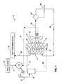
- Fig. 1 is a schematic illustration of one embodiment of a fuel compression system of the present invention.
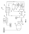
- Fig. 2 is a schematic illustration of a microturbine engine generator system for use with the present invention.
- Fig. 1 illustrates a fuel compression/conditioning system 10 that receives wet (i.e., containing water vapor) gas from a fuel source 20, removes condensed water from the gas, and delivers the gas to a fuel consuming device 30.
- the system 10 includes a compressor 35, a motor 40, a separator tank 45, an aftercooler 50, an oil cooler 55, a blower 60, a moisture separator 65, and a reheater 70.
- the fuel source 20 may be, for example, a waste water treatment facility, landfill, or other site from which gas is extracted.
- the impurities in the gas may be, for example, siloxanes or other contaminants that would cause pollution or damage to a combustion chamber and associated moving parts if not removed from the gas.
- the fuel consuming device 30 may be, for example, a flare that bums the gas to reduce the amount of unburned hydrocarbons that are released into the environment.
- the fuel consuming device may be an engine that uses the gas fuel for doing work. Examples of such engines include reciprocating engines, microturbine engines, and larger gas turbine engines. Examples of work done by such engines include production of electricity, driving chillers, refrigerators, or compressors, cogeneration of hot water, and raising, lowering, or otherwise moving objects.
- the compressor 35 may be, for example, an oil flooded screw compressor and is powered by the motor 40. Gas and oil mix in the compressor 35 while the pressure of the gas increases. The gas and oil become hot during compression. A flow of hot gas and oil flows out of the compressor (at 72) at a temperature of about 220°F in the illustrated embodiment.
- the flow of hot gas and oil then enters the separator tank 45, in which the gas rises to the top and the oil sinks to the bottom. From the separator tank 45, the gas is directed (at 75) to the aftercooler 50 and the oil is directed (at 80) to the oil cooler 55.
- Each of the aftercooler 50 and oil cooler 55 includes a first flow path for respective hot gas and hot oil.
- the aftercooler 50 and oil cooler 55 may take the form of any heat exchanger that provides the functionality describe herein, including, for example, counterflow or cross-flow plate-fin heat exchangers and tube-fin heat exchangers.
- the blower 60 blows relatively cool ambient air (at 81) through second flow paths in the aftercooler 50 and oil cooler 55 to cool the hot gas and hot oil.
- a fan or any other airflow device having the ability to move air across a heat exchanger may be used in place of the blower 60.
- the temperature of the air raises and a hot airflow (at 82) is generated.
- the gas temperature drops to about 15°F above ambient temperature
- the oil temperature drops to about 175°F, but in other embodiments the aftercooler 50 and oil cooler 55 may be sized to achieve other target temperatures.
- the gas may be termed a cool gas after exiting the aftercooler 50.
- the cool gas is directed to the moisture separator 65 (at 83) and the oil re-enters the compressor 35 (at 85) to be used again.
- the moisture separator 65 removes any water that may have condensed in the cool gas as a result of the drop in gas temperature across the aftercooler 50. Flowing out of the moisture separator 65 is gas that is still at a temperature of about 15°F above ambient, and is saturated (i.e., the gas is at its dew point). The saturated gas exits the moisture separator 65 (at 90) and enters one flow path in the reheater 70. Also flowing out of the moisture separator 65 (at 95) is water.
- the reheater 70 is positioned on the opposite side of the aftercooler 50 and oil cooler 55 from the blower 60 such that the hot airflow 82 (i.e., the air flowing out of the aftercooler 50 and oil cooler 55) flows through another flow path (i.e., a different flow path from the one through which the saturated gas is flowing) in the reheater 70.
- the reheater 70 may take the form of any heat exchanger that provides the functionality describe herein, including, for example, a counterflow or cross-flow plate-fin heat exchanger and tube-fin heat exchanger.
- the reheater 70 may be mounted on the aftercooler 50 and oil cooler 55, but in other embodiments it may be mounted separately.
- the reheater 70 heat is exchanged from the hot airflow to the saturated gas, such that the gas temperature raises above its dew point or saturation temperature.
- the gas may be termed "superheated" upon exiting (at 96) the reheater 70 because its temperature is raised above its saturation temperature.
- the reheater 70 is sized to generate the superheated gas 96 at a temperature of about 40°F above ambient temperature. This heating causes dew point suppression such that any remaining moisture becomes trapped in the gas and does not condense while the gas is being consumed in the fuel consuming device 30.
- Fig. 2 schematically illustrates one type of fuel consuming device that may be used in conjunction with the fuel conditioning system 10 described above.
- the illustrated fuel consuming device is a microturbine engine generator 100, which is useful in distributed power applications, and can even be mounted on skids and moved between job sites.
- Microturbine engine generators usually generate 2 MW of power or less, and are therefore relatively small when compared to power generators in power plants that are on the grid.
- the illustrated microturbine engine generator 100 includes a compressor 105, a recuperator 110, a combustor 115, a power turbine 120, and an electric power generator 125.
- Air is compressed in the compressor 105 and delivered to a cool side of the recuperator 110.
- the recuperator 110 may be, for example, a counterflow plate-fin type heat exchanger.
- the compressed air is preheated within the recuperator 110 and mixed with a gaseous fuel from a fuel supply (e.g., the superheated gas 96 from the fuel conditioning system 10 described above and illustrated in Fig. 1) to create a combustible mixture.
- the combustible mixture is combusted in the combustor 115 to create products of combustion.
- the products of combustion are then permitted to expand through the power turbine 120 to impart rotational energy to the power turbine 120.
- Rotation of the power turbine 120 drives operation of the electric generator 125 through an optional gearbox 130 to produce electrical power at a useful frequency.
- power electronics may be used in place of the gearbox 130 to condition the electrical signal into a useful frequency.
- the power turbine 120 and compressor 105 are coupled for rotation together via a shaft 135, so rotation of the power turbine 120 also drives rotation of the compressor 105.
- the power turbine 120 may only drive the power generator 125, and an additional gasifier turbine may be used to drive the compressor 105.
- the products of combustion are expanded through both the power turbine 120 and the gasifier turbine.
- the products of combustion Prior to exhausting the products of combustion from the microturbine engine 100, they flow into a hot side of the recuperator 110 to preheat the inflowing compressed air. Any remaining heat in the products of combustion is used for some other useful purpose (e.g., heating water) in a final heat exchanger 140 before the products of combustion are exhausted.
- a hot side of the recuperator 110 Prior to exhausting the products of combustion from the microturbine engine 100, they flow into a hot side of the recuperator 110 to preheat the inflowing compressed air. Any remaining heat in the products of combustion is used for some other useful purpose (e.g., heating water) in a final heat exchanger 140 before the products of combustion are exhausted.
Abstract
Description
- The present invention relates to a fuel compression system with internal reheat for dew point suppression.
- In one embodiment, the invention provides a system for conditioning a gas. The system includes a compressor for compressing and heating the gas into a hot gas; an airflow device generating an airflow; and a heat exchanger receiving in a first flow path the hot gas and in a second flow path the airflow. Heat is transferred from the hot gas to the airflow to generate a cool gas and hot airflow, and moisture condenses within the cool gas. A moisture separator separates condensed moisture from the cool gas to generate a saturated gas. A reheater receives in one flow path the saturated gas from the moisture separator and in another flow path the hot airflow from the heat exchanger. Heat is transferred in the reheater from the hot airflow to the saturated gas to generate a superheated gas having a temperature above the saturation temperature of the gas.
- In some embodiments, the compressor may include an oil-flooded compressor, such that oil mixes with the hot gas. Such embodiments may include a separator for separating the oil from the hot gas, and may also include an oil cooler that exchanges heat from the oil to the airflow.
- In another embodiment the invention provides a method for conditioning gas, the method comprising: compressing and heating the gas in a compressor to generate a hot gas; generating an airflow; exchanging heat between the hot gas and the airflow to generate a cool gas and a hot airflow; separating moisture from the cool gas to generate a saturated gas; and reheating the cool gas with the hot airflow to generate a superheated gas.
- In another embodiment, the invention provides a microturbine engine for generating electricity. The microturbine engine includes an air compressor, and a combustor that combusts a mixture of gas from a system for conditioning fuel as described above with compressed air from the air compressor. The combustor creates products of combustion. The microturbine engine further includes a power turbine rotating in response to expansion of the products of combustion. The turbine drives rotation of an electricity generator. The microturbine engine further includes a recuperator that exchanges heat from the products of combustion to the compressed air prior to the compressed air entering the combustor.
- Other aspects of the invention will become apparent by consideration of the detailed description and accompanying drawings.
- Fig. 1 is a schematic illustration of one embodiment of a fuel compression system of the present invention.
- Fig. 2 is a schematic illustration of a microturbine engine generator system for use with the present invention.
- Before any embodiments of the invention are explained in detail, it is to be understood that the invention is not limited in its application to the details of construction and the arrangement of components set forth in the following description or illustrated in the following drawings. The invention is capable of other embodiments and of being practiced or of being carried out in various ways. Also, it is to be understood that the phraseology and terminology used herein is for the purpose of description and should not be regarded as limiting. The use of "including," "comprising," or "having" and variations thereof herein is meant to encompass the items listed thereafter and equivalents thereof as well as additional items. Unless specified or limited otherwise, the terms "mounted," "connected," "supported," and "coupled" and variations thereof are used broadly and encompass both direct and indirect mountings, connections, supports, and couplings. Further, "connected" and "coupled" are not restricted to physical or mechanical connections or couplings.
- Fig. 1 illustrates a fuel compression/
conditioning system 10 that receives wet (i.e., containing water vapor) gas from afuel source 20, removes condensed water from the gas, and delivers the gas to afuel consuming device 30. Thesystem 10 includes acompressor 35, amotor 40, aseparator tank 45, anaftercooler 50, anoil cooler 55, ablower 60, amoisture separator 65, and areheater 70. - The
fuel source 20 may be, for example, a waste water treatment facility, landfill, or other site from which gas is extracted. The impurities in the gas may be, for example, siloxanes or other contaminants that would cause pollution or damage to a combustion chamber and associated moving parts if not removed from the gas. Thefuel consuming device 30 may be, for example, a flare that bums the gas to reduce the amount of unburned hydrocarbons that are released into the environment. Alternatively, the fuel consuming device may be an engine that uses the gas fuel for doing work. Examples of such engines include reciprocating engines, microturbine engines, and larger gas turbine engines. Examples of work done by such engines include production of electricity, driving chillers, refrigerators, or compressors, cogeneration of hot water, and raising, lowering, or otherwise moving objects. - Wet gas flows (at 71) from the
fuel source 20 to thecompressor 35. Thecompressor 35 may be, for example, an oil flooded screw compressor and is powered by themotor 40. Gas and oil mix in thecompressor 35 while the pressure of the gas increases. The gas and oil become hot during compression. A flow of hot gas and oil flows out of the compressor (at 72) at a temperature of about 220°F in the illustrated embodiment. - The flow of hot gas and oil then enters the
separator tank 45, in which the gas rises to the top and the oil sinks to the bottom. From theseparator tank 45, the gas is directed (at 75) to theaftercooler 50 and the oil is directed (at 80) to theoil cooler 55. Each of theaftercooler 50 andoil cooler 55 includes a first flow path for respective hot gas and hot oil. Theaftercooler 50 andoil cooler 55 may take the form of any heat exchanger that provides the functionality describe herein, including, for example, counterflow or cross-flow plate-fin heat exchangers and tube-fin heat exchangers. - The
blower 60 blows relatively cool ambient air (at 81) through second flow paths in theaftercooler 50 andoil cooler 55 to cool the hot gas and hot oil. In other embodiments, a fan or any other airflow device having the ability to move air across a heat exchanger may be used in place of theblower 60. As a result of heat transfer in theaftercooler 50 andoil cooler 55, the temperature of the air raises and a hot airflow (at 82) is generated. In the illustrated embodiment, the gas temperature drops to about 15°F above ambient temperature, and the oil temperature drops to about 175°F, but in other embodiments theaftercooler 50 andoil cooler 55 may be sized to achieve other target temperatures. The gas may be termed a cool gas after exiting theaftercooler 50. The cool gas is directed to the moisture separator 65 (at 83) and the oil re-enters the compressor 35 (at 85) to be used again. - The
moisture separator 65 removes any water that may have condensed in the cool gas as a result of the drop in gas temperature across theaftercooler 50. Flowing out of themoisture separator 65 is gas that is still at a temperature of about 15°F above ambient, and is saturated (i.e., the gas is at its dew point). The saturated gas exits the moisture separator 65 (at 90) and enters one flow path in thereheater 70. Also flowing out of the moisture separator 65 (at 95) is water. - The
reheater 70 is positioned on the opposite side of theaftercooler 50 andoil cooler 55 from theblower 60 such that the hot airflow 82 (i.e., the air flowing out of theaftercooler 50 and oil cooler 55) flows through another flow path (i.e., a different flow path from the one through which the saturated gas is flowing) in thereheater 70. Thereheater 70 may take the form of any heat exchanger that provides the functionality describe herein, including, for example, a counterflow or cross-flow plate-fin heat exchanger and tube-fin heat exchanger. In some embodiments, thereheater 70 may be mounted on theaftercooler 50 andoil cooler 55, but in other embodiments it may be mounted separately. - In the
reheater 70, heat is exchanged from the hot airflow to the saturated gas, such that the gas temperature raises above its dew point or saturation temperature. In this regard, the gas may be termed "superheated" upon exiting (at 96) thereheater 70 because its temperature is raised above its saturation temperature. In the illustrated embodiment, thereheater 70 is sized to generate thesuperheated gas 96 at a temperature of about 40°F above ambient temperature. This heating causes dew point suppression such that any remaining moisture becomes trapped in the gas and does not condense while the gas is being consumed in thefuel consuming device 30. - Fig. 2 schematically illustrates one type of fuel consuming device that may be used in conjunction with the
fuel conditioning system 10 described above. The illustrated fuel consuming device is amicroturbine engine generator 100, which is useful in distributed power applications, and can even be mounted on skids and moved between job sites. Microturbine engine generators usually generate 2 MW of power or less, and are therefore relatively small when compared to power generators in power plants that are on the grid. - The illustrated
microturbine engine generator 100 includes acompressor 105, arecuperator 110, acombustor 115, apower turbine 120, and anelectric power generator 125. Air is compressed in thecompressor 105 and delivered to a cool side of therecuperator 110. Therecuperator 110 may be, for example, a counterflow plate-fin type heat exchanger. The compressed air is preheated within therecuperator 110 and mixed with a gaseous fuel from a fuel supply (e.g., thesuperheated gas 96 from thefuel conditioning system 10 described above and illustrated in Fig. 1) to create a combustible mixture. - The combustible mixture is combusted in the
combustor 115 to create products of combustion. The products of combustion are then permitted to expand through thepower turbine 120 to impart rotational energy to thepower turbine 120. Rotation of thepower turbine 120 drives operation of theelectric generator 125 through anoptional gearbox 130 to produce electrical power at a useful frequency. In other embodiments, power electronics may be used in place of thegearbox 130 to condition the electrical signal into a useful frequency. In the illustratedmicroturbine 100, thepower turbine 120 andcompressor 105 are coupled for rotation together via ashaft 135, so rotation of thepower turbine 120 also drives rotation of thecompressor 105. In other embodiments, thepower turbine 120 may only drive thepower generator 125, and an additional gasifier turbine may be used to drive thecompressor 105. In such embodiments, the products of combustion are expanded through both thepower turbine 120 and the gasifier turbine. - Prior to exhausting the products of combustion from the
microturbine engine 100, they flow into a hot side of therecuperator 110 to preheat the inflowing compressed air. Any remaining heat in the products of combustion is used for some other useful purpose (e.g., heating water) in afinal heat exchanger 140 before the products of combustion are exhausted. - Various features and advantages of the invention are set forth in the following claims.
- Attention is directed to all papers and documents which are filed concurrently with or previous to this specification in connection with this application and which are open to public inspection with this specification, and the contents of all such papers and documents are incorporated herein by reference.
- All of the features disclosed in this specification (including any accompanying claims, abstract and drawings), and/or all of the steps of any method or process so disclosed, may be combined in any combination, except combinations where at least some of such features and/or steps are mutually exclusive.
- Each feature disclosed in this specification (including any accompanying claims, abstract and drawings) may be replaced by alternative features serving the same, equivalent or similar purpose, unless expressly stated otherwise. Thus, unless expressly stated otherwise, each feature disclosed is one example only of a generic series of equivalent or similar features.
- The invention is not restricted to the details of the foregoing embodiment(s). The invention extends to any novel one, or any novel combination, of the features disclosed in this specification (including any accompanying claims, abstract and drawings), or to any novel one, or any novel combination, of the steps of any method or process so disclosed.
Claims (17)
- A system for conditioning a gas, the system comprising:a compressor for compressing and heating the gas into a hot gas;an airflow device generating an airflow;a heat exchanger receiving in a first flow path the hot gas and in a second flow path the airflow, such that heat is transferred from the hot gas to the airflow to generate a cool gas and hot airflow, wherein moisture condenses within the cool gas;a moisture separator for separating condensed moisture from the cool gas to generate a saturated gas; anda reheater receiving in one flow path the saturated gas from the moisture separator and in another flow path the hot airflow from the heat exchanger, such that heat is transferred from the hot airflow to the saturated gas to generate a superheated gas having a temperature above the saturation temperature of the gas.
- The system of claim 1, wherein the compressor includes an oil-flooded compressor and wherein the hot gas includes hot oil; the system further comprising a separator adapted to separate the hot oil from the hot gas.
- The system of claim 2, wherein the heat exchanger includes an aftercooler and an oil cooler; wherein the heat exchanger receives in another flow path the hot oil from the separator; and wherein heat is transferred from the hot oil to the airflow to generate a cool oil and contributing heat to the hot airflow.
- The system of claim 1, wherein the reheater is mounted on the heat exchanger.
- The system of claim 1, wherein the airflow device generates an airflow of ambient air.
- The system of claim 5, wherein the heat exchanger is sized to generate the cool gas at a temperature of about 15°F above the temperature of the ambient airflow.
- The system of claim 1, wherein the reheater is sized to generate the superheated gas at a temperature of about 40°F above ambient temperature.
- A method for conditioning gas, the method comprising:compressing and heating the gas in a compressor to generate a hot gas;generating an airflow;exchanging heat between the hot gas and the airflow to generate a cool gas and a hot airflow;separating moisture from the cool gas to generate a saturated gas; andreheating the cool gas with the hot airflow to generate a superheated gas.
- The method of claim 8, wherein compressing and heating the gas generates a hot gas having a temperature of about 220°F.
- The method of claim 8, wherein the compressing step is performed with an oil-flooded compressor, such that the hot gas includes hot oil; the method further comprising separating the hot oil from the hot gas prior to the exchanging step.
- The method of claim 10, wherein the exchanging step includes exchanging heat from both the hot oil and the hot gas to the airflow.
- The method of claim 8, wherein the exchanging step is performed with a heat exchanger and the reheating step is performed with a reheater, the method further comprising mounting the reheater on the heat exchanger.
- The method of claim 8, wherein generating an airflow step is performed with a blower, and wherein the airflow is at ambient temperature.
- The method of claim 13, wherein exchanging step generates the cool gas at a temperature of about 15°F above the temperature of the ambient airflow.
- The method of claim 13, wherein the reheating step includes generating the superheated gas at a temperature of about 40°F above ambient temperature.
- A microturbine engine generator comprising:an air compressor creating a flow of compressed air;a fuel conditioner including a gas compressor for compressing and heating a gas, an aftercooler for cooling the gas and heating a flow of air, a moisture separator for separating condensed water from the cooled gas, and a reheater for reheating the cooled gas with the heated flow of air to create a superheated gas;a combustor for combusting a mixture of the compressed air with the superheated gas to create products of combustion;a power turbine rotating in response to expansion of the products of combustion;a generator generating electricity in response to rotation of the power turbine; anda recuperator preheating the compressed air with the products of combustion prior to the compressed air flowing into the combustor.
- The microturbine of claim 16, wherein the gas compressor in the fuel conditioner includes an oil-flooded compressor, the gas compressor further including a separator for separating oil from the compressed gas; and an oil cooler for cooling the oil and heating the flow of air.
Applications Claiming Priority (1)
| Application Number | Priority Date | Filing Date | Title |
|---|---|---|---|
| US11/552,182 US7753975B2 (en) | 2006-10-24 | 2006-10-24 | Fuel compression system with internal reheat for dew point suppression |
Publications (2)
| Publication Number | Publication Date |
|---|---|
| EP1947348A2 true EP1947348A2 (en) | 2008-07-23 |
| EP1947348A3 EP1947348A3 (en) | 2014-09-17 |
Family
ID=39156264
Family Applications (1)
| Application Number | Title | Priority Date | Filing Date |
|---|---|---|---|
| EP07253470.4A Withdrawn EP1947348A3 (en) | 2006-10-24 | 2007-09-01 | Fuel compression system with internal reheat for dew point suppression |
Country Status (4)
| Country | Link |
|---|---|
| US (1) | US7753975B2 (en) |
| EP (1) | EP1947348A3 (en) |
| CN (1) | CN101201016B (en) |
| RU (1) | RU2467190C2 (en) |
Cited By (1)
| Publication number | Priority date | Publication date | Assignee | Title |
|---|---|---|---|---|
| CN102996489A (en) * | 2011-09-08 | 2013-03-27 | 中国石油化工股份有限公司 | Inter-section scale inhibition method for centrifugal natural gas compressor set |
Families Citing this family (5)
| Publication number | Priority date | Publication date | Assignee | Title |
|---|---|---|---|---|
| US7645322B2 (en) * | 2006-09-15 | 2010-01-12 | Ingersoll Rand Energy Systems Corporation | System and method for removing water and siloxanes from gas |
| US10995995B2 (en) | 2014-06-10 | 2021-05-04 | Vmac Global Technology Inc. | Methods and apparatus for simultaneously cooling and separating a mixture of hot gas and liquid |
| RU2623133C1 (en) * | 2016-06-07 | 2017-06-22 | Федеральное государственное бюджетное образовательное учреждение высшего образования "Московский политехнический университет" | System of heat exchange in small-sized gas-turbine energy installations (microturbines) with rotating rotary regenerative heat exchanger |
| KR102592232B1 (en) * | 2016-07-15 | 2023-10-20 | 한화파워시스템 주식회사 | Air cooling system for fluidic machine |
| RU2650446C1 (en) * | 2017-06-22 | 2018-04-13 | федеральное государственное бюджетное образовательное учреждение высшего образования "Национальный исследовательский университет "МЭИ" (ФГБОУ ВО "НИУ "МЭИ") | Low-capacity steam compressing unit |
Citations (6)
| Publication number | Priority date | Publication date | Assignee | Title |
|---|---|---|---|---|
| US3785755A (en) * | 1971-11-22 | 1974-01-15 | Rogers Machinery Co Inc | Air compressor system |
| EP0230940A2 (en) * | 1986-01-22 | 1987-08-05 | Pressluft-Frantz GmbH | Air compressor provided with a dehumidification device |
| EP0979670A1 (en) * | 1998-08-13 | 2000-02-16 | Flair Filtration & Drying B.V. | Apparatus for removing condensable material from a gas |
| US20030021701A1 (en) * | 2001-07-30 | 2003-01-30 | Kolodziej Robert M. | Air cooled packaged multi-stage centrifugal compressor system |
| US20040042909A1 (en) * | 2002-09-02 | 2004-03-04 | Kanamoto Co., Ltd. | Compression feed for high humidity fuel gas |
| WO2005030367A1 (en) * | 2003-10-01 | 2005-04-07 | Atlas Copco Airpower, Naamloze Vennootschap | Improved method for separating gases from a gas mixture and device for applying such a method |
Family Cites Families (8)
| Publication number | Priority date | Publication date | Assignee | Title |
|---|---|---|---|---|
| US4041697A (en) * | 1975-07-17 | 1977-08-16 | The United States Of America As Represented By The Administrator Of The National Aeronautics And Space Administration | Oil cooling system for a gas turbine engine |
| US4120150A (en) * | 1977-05-17 | 1978-10-17 | The United States Of America As Represented By The Secretary Of The Air Force | Compact fuel-to-air heat exchanger for jet engine application |
| SU1550199A1 (en) * | 1988-05-30 | 1990-03-15 | Всесоюзный научно-исследовательский и проектный институт по транспорту природного газа | Method and apparatus for processing fuel gas |
| US5845505A (en) * | 1997-05-30 | 1998-12-08 | American Precision Industries Inc. | Precooler/chiller/reheater heat exchanger for air dryers |
| EP0994806B1 (en) * | 1997-07-11 | 2002-06-05 | Honeywell International Inc. | Air cycle environmental control system with vapor cycle system assisted condensation |
| RU2193096C1 (en) * | 2001-08-02 | 2002-11-20 | Дочернее открытое акционерное общество "Центральное конструкторское бюро нефтеаппаратуры" Открытого акционерного общества "Газпром" | Method of operation of gas turbine plant |
| ITMI20011917A1 (en) * | 2001-09-14 | 2003-03-14 | Domnick Hunter Hiross S P A | GROUP OF HEAT EXCHANGERS FOR COMPRESSED REFRIGERATION GAS DRYERS |
| SE524938C2 (en) * | 2003-02-03 | 2004-10-26 | Ep Technology Ab | Heat exchanger and method for drying a moist medium |
-
2006
- 2006-10-24 US US11/552,182 patent/US7753975B2/en not_active Expired - Fee Related
-
2007
- 2007-09-01 EP EP07253470.4A patent/EP1947348A3/en not_active Withdrawn
- 2007-10-23 RU RU2007139328/06A patent/RU2467190C2/en not_active IP Right Cessation
- 2007-10-24 CN CN2007101677724A patent/CN101201016B/en not_active Expired - Fee Related
Patent Citations (6)
| Publication number | Priority date | Publication date | Assignee | Title |
|---|---|---|---|---|
| US3785755A (en) * | 1971-11-22 | 1974-01-15 | Rogers Machinery Co Inc | Air compressor system |
| EP0230940A2 (en) * | 1986-01-22 | 1987-08-05 | Pressluft-Frantz GmbH | Air compressor provided with a dehumidification device |
| EP0979670A1 (en) * | 1998-08-13 | 2000-02-16 | Flair Filtration & Drying B.V. | Apparatus for removing condensable material from a gas |
| US20030021701A1 (en) * | 2001-07-30 | 2003-01-30 | Kolodziej Robert M. | Air cooled packaged multi-stage centrifugal compressor system |
| US20040042909A1 (en) * | 2002-09-02 | 2004-03-04 | Kanamoto Co., Ltd. | Compression feed for high humidity fuel gas |
| WO2005030367A1 (en) * | 2003-10-01 | 2005-04-07 | Atlas Copco Airpower, Naamloze Vennootschap | Improved method for separating gases from a gas mixture and device for applying such a method |
Cited By (1)
| Publication number | Priority date | Publication date | Assignee | Title |
|---|---|---|---|---|
| CN102996489A (en) * | 2011-09-08 | 2013-03-27 | 中国石油化工股份有限公司 | Inter-section scale inhibition method for centrifugal natural gas compressor set |
Also Published As
| Publication number | Publication date |
|---|---|
| CN101201016A (en) | 2008-06-18 |
| US20080092517A1 (en) | 2008-04-24 |
| CN101201016B (en) | 2012-06-13 |
| EP1947348A3 (en) | 2014-09-17 |
| RU2467190C2 (en) | 2012-11-20 |
| RU2007139328A (en) | 2009-04-27 |
| US7753975B2 (en) | 2010-07-13 |
Similar Documents
| Publication | Publication Date | Title |
|---|---|---|
| JP6921080B2 (en) | Reverse Brayton cycle heat engine | |
| JP5508763B2 (en) | Turbine system with exhaust gas recirculation and reheat | |
| US7861526B2 (en) | Steam generation plant and method for operation and retrofitting of a steam generation plant | |
| US9410451B2 (en) | Gas turbine engine with integrated bottoming cycle system | |
| US7959710B2 (en) | System and method for removing water and siloxanes from gas | |
| US8769953B2 (en) | Method for operating a power plant and power plant | |
| EP1947348A2 (en) | Fuel compression system with internal reheat for dew point suppression | |
| US20100229525A1 (en) | Turbine combustion air system | |
| EP1992883A2 (en) | Integrated absorption refrigeration and dehumidification system | |
| CN102345511A (en) | A hybrid power generation system and a method thereof | |
| JP2012117517A (en) | Heat exchanger for combined cycle power plant | |
| US20070039305A1 (en) | Lubricating Oil Heat Recovery System for Turbine Engines | |
| US20210239041A1 (en) | Apparatus, process and thermodynamic cycle for power generation with heat recovery | |
| KR20150038412A (en) | Dual-end drive gas turbine | |
| CN100458121C (en) | Atmospheric pressure combustion turbine system | |
| Czaja et al. | Selection of gas turbine air bottoming cycle for polish compressor stations | |
| CA2704281C (en) | A system for converting waste heat from a waste heat source into shaft power | |
| CN103620167A (en) | Waste heat recovery installation | |
| US7647762B2 (en) | Combined apparatus for fluid heating and electrical power generation | |
| CN103635661A (en) | Waste heat recovery installation | |
| JPH10325336A (en) | Gas turbine power generating system | |
| JP2021032241A (en) | Volume expander | |
| JP2005307820A (en) | Gas turbine facilities | |
| TH53205B (en) | Methods and systems for power generation | |
| TH37438A (en) | Combined power plants around the multi-fuel cycle |
Legal Events
| Date | Code | Title | Description |
|---|---|---|---|
| PUAI | Public reference made under article 153(3) epc to a published international application that has entered the european phase |
Free format text: ORIGINAL CODE: 0009012 |
|
| AK | Designated contracting states |
Kind code of ref document: A2 Designated state(s): AT BE BG CH CY CZ DE DK EE ES FI FR GB GR HU IE IS IT LI LT LU LV MC MT NL PL PT RO SE SI SK TR |
|
| AX | Request for extension of the european patent |
Extension state: AL BA HR MK RS |
|
| RAP1 | Party data changed (applicant data changed or rights of an application transferred) |
Owner name: INGERSOLL-RAND ENERGY SYSTEMS CORPORATION |
|
| RAP1 | Party data changed (applicant data changed or rights of an application transferred) |
Owner name: FLEXENERGY ENERGY SYSTEMS, INC. |
|
| PUAL | Search report despatched |
Free format text: ORIGINAL CODE: 0009013 |
|
| AK | Designated contracting states |
Kind code of ref document: A3 Designated state(s): AT BE BG CH CY CZ DE DK EE ES FI FR GB GR HU IE IS IT LI LT LU LV MC MT NL PL PT RO SE SI SK TR |
|
| AX | Request for extension of the european patent |
Extension state: AL BA HR MK RS |
|
| RIC1 | Information provided on ipc code assigned before grant |
Ipc: B01D 53/26 20060101ALI20140814BHEP Ipc: F04D 29/58 20060101AFI20140814BHEP |
|
| AKX | Designation fees paid |
Designated state(s): DE FR GB IT |
|
| AXX | Extension fees paid |
Extension state: BA Extension state: RS Extension state: AL Extension state: HR Extension state: MK |
|
| STAA | Information on the status of an ep patent application or granted ep patent |
Free format text: STATUS: THE APPLICATION IS DEEMED TO BE WITHDRAWN |
|
| 18D | Application deemed to be withdrawn |
Effective date: 20150318 |