EP0230940A2 - Air compressor provided with a dehumidification device - Google Patents
Air compressor provided with a dehumidification device Download PDFInfo
- Publication number
- EP0230940A2 EP0230940A2 EP87100588A EP87100588A EP0230940A2 EP 0230940 A2 EP0230940 A2 EP 0230940A2 EP 87100588 A EP87100588 A EP 87100588A EP 87100588 A EP87100588 A EP 87100588A EP 0230940 A2 EP0230940 A2 EP 0230940A2
- Authority
- EP
- European Patent Office
- Prior art keywords
- air
- heat exchanger
- cooled
- compressor according
- aftercooler
- Prior art date
- Legal status (The legal status is an assumption and is not a legal conclusion. Google has not performed a legal analysis and makes no representation as to the accuracy of the status listed.)
- Withdrawn
Links
Images
Classifications
-
- B—PERFORMING OPERATIONS; TRANSPORTING
- B01—PHYSICAL OR CHEMICAL PROCESSES OR APPARATUS IN GENERAL
- B01D—SEPARATION
- B01D53/00—Separation of gases or vapours; Recovering vapours of volatile solvents from gases; Chemical or biological purification of waste gases, e.g. engine exhaust gases, smoke, fumes, flue gases, aerosols
- B01D53/26—Drying gases or vapours
- B01D53/265—Drying gases or vapours by refrigeration (condensation)
-
- F—MECHANICAL ENGINEERING; LIGHTING; HEATING; WEAPONS; BLASTING
- F28—HEAT EXCHANGE IN GENERAL
- F28D—HEAT-EXCHANGE APPARATUS, NOT PROVIDED FOR IN ANOTHER SUBCLASS, IN WHICH THE HEAT-EXCHANGE MEDIA DO NOT COME INTO DIRECT CONTACT
- F28D7/00—Heat-exchange apparatus having stationary tubular conduit assemblies for both heat-exchange media, the media being in contact with different sides of a conduit wall
- F28D7/16—Heat-exchange apparatus having stationary tubular conduit assemblies for both heat-exchange media, the media being in contact with different sides of a conduit wall the conduits being arranged in parallel spaced relation
-
- F—MECHANICAL ENGINEERING; LIGHTING; HEATING; WEAPONS; BLASTING
- F02—COMBUSTION ENGINES; HOT-GAS OR COMBUSTION-PRODUCT ENGINE PLANTS
- F02B—INTERNAL-COMBUSTION PISTON ENGINES; COMBUSTION ENGINES IN GENERAL
- F02B3/00—Engines characterised by air compression and subsequent fuel addition
- F02B3/06—Engines characterised by air compression and subsequent fuel addition with compression ignition
-
- F—MECHANICAL ENGINEERING; LIGHTING; HEATING; WEAPONS; BLASTING
- F28—HEAT EXCHANGE IN GENERAL
- F28D—HEAT-EXCHANGE APPARATUS, NOT PROVIDED FOR IN ANOTHER SUBCLASS, IN WHICH THE HEAT-EXCHANGE MEDIA DO NOT COME INTO DIRECT CONTACT
- F28D21/00—Heat-exchange apparatus not covered by any of the groups F28D1/00 - F28D20/00
- F28D2021/0019—Other heat exchangers for particular applications; Heat exchange systems not otherwise provided for
- F28D2021/0038—Other heat exchangers for particular applications; Heat exchange systems not otherwise provided for for drying or dehumidifying gases or vapours
Definitions
- the invention relates to an air-cooled, in particular mobile compressor with integrated compressed air preparation, with a compressor, in particular a screw compressor, and with a drive unit, in particular a diesel engine, for the compressor.
- the invention is therefore based on the object of creating an air-cooled compressor of the type mentioned, in which the compressed air is improved with regard to the moisture content.
- an air-cooled aftercooler provided with a condensate separator is arranged in the compressed air stream in order to cool the compressed air from the compression temperature at the aftercooler inlet to a temperature of about 10 ° C. above the intake temperature, and in that a heat exchanger for reheating in the aftercooler the compressed air is provided, which is arranged on the exhaust air side in the exhaust area of the drive unit.
- the solution according to the invention thus proposes an air-cooled, in particular mobile, compressor with integrated compressed air treatment, in which the air heated by the compression, in a modern screw compressor to about 60 ° C above the intake temperature, is cooled to a temperature with an oversized aftercooler, which is about 10 ° C above the suction temperature.
- a considerable part of the water vapor present in the air condenses out and can be separated out by the condensate separator.
- a condensate excretion of about 80% takes place; There is still 20% water vapor in the compressed air, which can condense if the compressed air temperature is reduced further and could lead to malfunctions.
- the invention provides for the further measure according to which the aftercooler is followed by a heat exchanger for reheating the compressed air, which is located on the exhaust air side in the exhaust duct of the drive unit.
- a heat exchanger for reheating the compressed air which is located on the exhaust air side in the exhaust duct of the drive unit.
- a compressor according to the invention is therefore also outstandingly suitable for winter operation.
- Compressors of the type according to the invention have, due to the necessary noise damping measures, in particular if they are diesel-driven, relatively large amounts of cooling air which are fed to the respective machine parts, in particular the drive unit, for example the diesel engine, and / or the compressor.
- This compressor is therefore adequately equipped with supply air and exhaust air ducts.
- an air-cooled compressor according to the invention with a cooling air duct for the drive unit and / or the compressor, which has a supply air and an exhaust air side there is therefore another feature of the invention is that the air-cooled aftercooler is arranged in a cooling air shaft on the supply air side.
- the air-cooled aftercooler and condensate separator can be accommodated in the already existing cooling air duct by slightly changing the casing of the compressor compared to conventional compressors.
- the condensate separator has air baffles which are attached in particular in a head part in order to set the compressed air flow in a rotating movement. Due to the different specific weights, the water or condensate drops collect on the inner wall of the separator and flow down from there into a condensate collector, which is expediently provided with an automatic float circuit, which opens depending on the condensate level and opens the condensate via a hose line leads outside.
- an additional, in particular spring-loaded valve can be provided, which opens during each control process of the compressor in order to blow off any condensate present in the cooler or piping system. This prevents freezing.
- connection tap for a breathing air hose is arranged directly after the aftercooler or the condensate separator. This measure is Particularly important if the compressor is used for sandblasting or the like. Dust-forming work, the worker wearing a respirator. This measure according to the invention gives the worker clean and cooled air. An activated carbon filter can easily be attached to completely filter out the already small traces of oil, maximum 10 mg / m3.
- the compression and combustion air is expediently taken from the atmosphere and not from the interior of the compressor system.
- a further utilization of the exhaust gas heat is achieved according to a particularly advantageous embodiment of the invention in that the heat exchanger has a connection which is connected to an exhaust system of an internal combustion engine.
- the exhaust gas heat of the internal combustion engine is used in an optimal way to heat compressed air and thus bind the residual moisture. After a short operating time of the internal combustion engine, a temperature of approximately 350 to 520 ° C becomes effective in the heat exchanger depending on the exhaust gas temperature. This enables a compressed air temperature of over 100 ° C to be achieved.
- the heat exchanger can be designed as a tube bundle heat exchanger.
- the heat exchanger is a cross-flow heat exchanger.
- an optimal heat yield can be achieved with relatively little structural complexity.
- this heat exchanger has a flow chamber or outflow chamber free of heat exchanger tubes and a crossflow chamber arranged between them.
- a structurally particularly simple and space-saving embodiment provides that the heat exchanger has a cylindrical shape.
- the compressed air connections are provided in particular on the cylindrical circumference of the heat exchanger.
- the dimensioning of the outer tube of the heat exchanger and the compressed air connections, as well as the free passage cross section within the cross-flow chamber is expediently chosen so that the maximum pressure resistance is in the range of 0.7 bar.
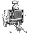
- Fig. 1 shows an air-cooled, mobile, super-silenced screw compressor, which is driven by a diesel engine as a drive unit.
- the mobile compressor is arranged on a single-axle chassis 32.
- On the chassis 32 there is a box-shaped structure 34 which receives an air-cooled diesel engine and an oil-cooled screw compressor.
- the front part of the structure 34 forms a supply air shaft, in which an air-cooled aftercooler 24 including a condensate separator and an automatic condensate drain is arranged.
- an intake filter 36 is arranged above the structure 34. This special arrangement outside the interior of the system removes the compression and combustion air from the atmosphere and not from the interior.
- the compression and combustion temperatures are about 5 ° C lower and the cooling air flow is greater. There are also lower levels of dust in the atmospheric air because the suction point is moved upwards.
- the compressed air flow is through air baffles, which are in the head part of the condensate separator are brought into a rotating movement. Due to the different specific weights, the condensate drops collect on the inner wall of the condensate separator and flow from there down into a condensate collector, which opens depending on the condensate level by an automatic float circuit and discharges the condensate to the outside via a hose line.
- An additional spring-loaded outlet valve opens each time the compressor is regulated to allow any condensate to enter the cooler or piping system.
- connection tap for a breathing air hose with which a worker, for example when sandblasting, can be supplied with clean and cooled breathing air.
- the compressed air is then passed through a heat exchanger which is arranged in the exhaust area of the drive unit, in particular a diesel engine.
- the compressed air is heated, for example, in the form of a tube bundle heat exchanger, for example to about 60 ° C. above the initial temperature.
- the relative humidity is reduced from about 70% to about 10%.
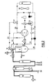
- FIG. 2 The specific structure of an air-cooled compressor according to the invention results from the diagram of FIG. 2 in conjunction with the list of reference symbols below.
- the air is drawn in via an air filter 1 and fed to the compressor 3.
- a throttle valve 2 In the connecting line between the air filter 1 and the compressor 3 there is a throttle valve 2 with an actuating cylinder 13.
- a check valve 4 In the oil-air line 21 between the compressor 3 and the oil tank 5 with an oil separator 6 there is a check valve 4.
- the aftercooler 24 is followed by the condensate separator 29.
- a regulating outlet valve 25 and an intermittent blow-off valve 26 arranged, each open when regulating the compressor 3 or when it is suspended and ensure that the condensate is drained to avoid freezing.
- the condensate collecting due to the condensate separator 29 is drained down via an automatic condensate drain 27.
- a breathing air connection tap 28 is connected to the compressed air line.
- the compressed air line itself leads through a heat exchanger 30 to the connection tap 31 for the connection of the compressed air operated tool or the like.
- a safety valve 9 is connected to the oil container 5.
- the oil of the oil container 5 intended for cooling the compressor 3 is guided via the oil line 20 and an oil filter 14 through an oil cooler 16 which is acted upon by a fan 18.
- a control valve controlled by a thermostat 15 lies in a bypass to the oil cooler 16.
- the control line 23 also leads to a blow-off valve 10 in the air line 19 immediately after the fine oil separator 6.
- a control line 23 also leads via a filter and water separator 11 and a control valve 12 to the actuating cylinder 13.
- the fine oil separator 6 is also via a Oil suction line 22 connected to the compressor 3.
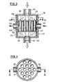
- the heat exchanger 30 has a tubular housing 41 which is closed by means of an upper cover 42 and a lower cover 43.
- the tubular housing 41 here consists of three tubular sections 41a, 41b, 41c.
- the covers 42, 43 are each provided with connecting pieces 44, 45.
- In the central region of the interior of the housing two intermediate walls 46, 47 are drawn in, so that an inflow chamber 48 is formed above the upper intermediate wall and an outflow chamber 49 is formed below the lower intermediate wall 47.
- a cross-flow chamber 50 extends between the intermediate walls 46, 47.
- heat exchanger tubes are arranged parallel to the longitudinal axis of the heat exchanger 30, one of which is designated 51.
- the heat exchanger tubes 51 are inserted into openings which are provided in the intermediate walls 46, 47 and are arranged in alignment. The ends of the heat exchanger tubes 51 are flush with the partitions 46, 47. In the area of the cross-flow chamber 50, connection pieces 52, 53 are provided on the tubular part of the housing 41 on the outside, via which the compressed air is supplied or discharged.
- the entire heat exchanger 30 is designed as a welded construction using simple tubular parts.
- the connecting pieces 44, 45 (diameter d) and the inflow chambers 48, 49 and the heat exchanger tubes 51 and their number are dimensioned so that the permissible exhaust gas pressure of the respective engine brands is not exceeded.
- the dimensioning of the tubular housing part 40 (diameter D) and the connecting piece 52, 53 for the compressed air and the free passage cross section within the cross-flow chamber 50 is selected so that the maximum pressure resistance is about 0.7 bar.
Landscapes
- Engineering & Computer Science (AREA)
- Physics & Mathematics (AREA)
- Thermal Sciences (AREA)
- Chemical & Material Sciences (AREA)
- Analytical Chemistry (AREA)
- General Chemical & Material Sciences (AREA)
- Oil, Petroleum & Natural Gas (AREA)
- Chemical Kinetics & Catalysis (AREA)
- Mechanical Engineering (AREA)
- General Engineering & Computer Science (AREA)
- Compressor (AREA)
- Applications Or Details Of Rotary Compressors (AREA)
Abstract
Description
Die Erfindung bezieht sich auf einen luftgekühlten, insbesondere fahrbaren Kompressor mit integrierter Druckluftaufbereitung, mit einem Verdichter, insbesonder einem Schraubenverdichter, und mit einem Antriebsaggregat, insbesondere einem Dieselmotor, für den Verdichter.The invention relates to an air-cooled, in particular mobile compressor with integrated compressed air preparation, with a compressor, in particular a screw compressor, and with a drive unit, in particular a diesel engine, for the compressor.
Bei derartigen, beispielsweise im Baugewerbe eingesetzten luftgekühlten Kompressoren ist die Druckluftqualität hinsichtlich des Feuchtigkeitsgehaltes als zu naß zu bezeichnen. Infolge dessen können sich beim Betrieb von Druckluftwerkzeugen durch das anfallende Kondensat bedingte Funktionsstörungen ergeben. So fallen beispielsweise bei einer 10-cbm-Schraubenverdichteranlage pro Tag, je nach herrschender Luftfeuchtigkeit, rund 30 l Wasser an. Bereits ab 10° C Ansaugtemperatur kann es durch den Temperaturabfall der sich entspannenden Luft zu einer Vereisung der Werkzeuge kommen. Das Wasser behindert in den Werkzeugen auch die notwendige Schmierung. Erhöhter Verschleiß und Materialdefekte sind die Folge.In such air-cooled compressors, used for example in the construction industry, the compressed air quality with regard to the moisture content can be described as too wet. As a result, malfunctions caused by the condensate can occur when operating compressed air tools. For example, with a 10-cbm screw compressor system, depending on the prevailing air humidity, around 30 l of water are generated each day. Even from 10 ° C suction temperature, the temperature of the relaxing air can cause the tools to freeze. The water also hinders the necessary lubrication in the tools. The result is increased wear and material defects.
Der Erfindung liegt daher die Aufgabe zugrunde, einen luftgekühlten Kompressor der eingangs genannten Art zu schaffen, bei dem die Druckluft hinsichtlich des Feuchtigkeitsgehaltes verbessert ist.The invention is therefore based on the object of creating an air-cooled compressor of the type mentioned, in which the compressed air is improved with regard to the moisture content.
Diese Aufgabe wird erfindungsgemäß dadurch gelöst, daß ein luftgekühlter, mit einem Kondensatabscheider versehener Nachkühler im Druckluftstrom angeordnet ist, um die verdichtete Luft von der Verdichtungstemperatur am Nachkühlereintritt auf eine Temperatur von etwa 10° C über Ansaugtemperatur abzukühlen, und daß im Nachkühler ein Wärmetauscher zum Nachwärmen der Druckluft vorgesehen ist, der auf der Abluftseite im Abgasbereich des Antriebsaggregats angeordnet ist.This object is achieved in that an air-cooled aftercooler provided with a condensate separator is arranged in the compressed air stream in order to cool the compressed air from the compression temperature at the aftercooler inlet to a temperature of about 10 ° C. above the intake temperature, and in that a heat exchanger for reheating in the aftercooler the compressed air is provided, which is arranged on the exhaust air side in the exhaust area of the drive unit.
Mit der erfindungsgemäßen Lösung wird also ein luftgekühlter, insbesondere fahrbarer Kompressor mit integrierter Druckluftaufbereitung vorgeschlagen, bei dem die durch die Komprimierung erwärmte Luft, bei einem modernen Schraubenverdichter auf etwa 60° C über Ansaugtemperatur, mit einem überdimensionierten Nachkühler auf eine Temperatur abgekühlt wird, die etwa 10 ° C über der Ansaugtemperatur liegt. Hierbei kondensiert ein erheblicher Teil des in der Luft vorhandenen Wasserdampfes aus und kann durch den Kondensatabscheider ausgeschieden werden. Mit dieser Maßnahme erfolgt eine Kondensatausscheidung von etwa 80 %; noch 20 % Wasserdampf befinden sich in der Druckluft, die bei weiterer Reduzierung der Drucklufttemperatur kondensieren und zu Betriebsstörungen führen könnten. Um dies zu vermeiden sieht die Erfindung die weitere Maßnahme vor, wonach dem Nachkühler ein Wärmetauscher zum Nachwärmen der Druckluft nachgeordnet ist, der auf der Abluftseite im Abgaskanal des Antriebsaggregates liegt. Hierdurch wird der Wärmeinhalt des Abgases des Antriebs aggregates unmittelbar ausgenutzt. Die Druckluft wird dabei in dem Wärmetauscher wieder auf etwa 60° C über Ansaugtemperatur erwärmt und folglich die relative Luftfeuchtigkeit erheblich, beispielsweise von etwa 70 % auf etwa 10 %, reduziert. Berücksichtigt man beispielsweise, daß ein 3/4 Zoll-Schlauch ein Durchsatzvermögen von 3 m³ /min, einen Temperatuverlust von 0,5° C/min, bezogen auf 20° C Außentemperatur, aufgrund von Abstrahlungswäre bestizt, so fällt bei einer Schlauchlänge von etwa 60 m kein Kondensat aus, so daß auch über diese Länge von dem erfindungsgemäßen Baukompressor "trockene" Luft geliefert werden kann. Mit dieser weiteren erfindungsgemäßen Maßnahme wird also vermieden, daß die in der Druckluft zunächst verbleibende Restluftfeuchte von 20 bis 25 % durch weiteren Wärmeverlust (wie er in Schlauchleitungen bzw. Druckbehältern auftreten kann) kondensiert. Durch das erfindungsgemäße Nachwärmen der Druckluft unter Ausnutzung der Wärme des Abgases des Antriebsgases ist es möglich, auf äußerst wirtschaftliche Weise relativ trockene Luft (abhängig vom Schlauchdurchmesser und der Schlauchlänge) zu erzeugen und Schäden innerhalb der Verbraucher zu vermeiden. Außerdem eignet sich ein erfindungsgemäßer Kompressor dadurch auch auf hervorragende Weise für den Winterbetrieb.The solution according to the invention thus proposes an air-cooled, in particular mobile, compressor with integrated compressed air treatment, in which the air heated by the compression, in a modern screw compressor to about 60 ° C above the intake temperature, is cooled to a temperature with an oversized aftercooler, which is about 10 ° C above the suction temperature. Here, a considerable part of the water vapor present in the air condenses out and can be separated out by the condensate separator. With this measure, a condensate excretion of about 80% takes place; There is still 20% water vapor in the compressed air, which can condense if the compressed air temperature is reduced further and could lead to malfunctions. In order to avoid this, the invention provides for the further measure according to which the aftercooler is followed by a heat exchanger for reheating the compressed air, which is located on the exhaust air side in the exhaust duct of the drive unit. As a result, the heat content of the exhaust gas of the drive aggregates used immediately. The compressed air is heated in the heat exchanger again to about 60 ° C above the intake temperature and consequently the relative air humidity is considerably reduced, for example from about 70% to about 10%. If one takes into account, for example, that a 3/4 inch hose has a throughput capacity of 3 m³ / min, a temperature loss of 0.5 ° C / min, based on an outside temperature of 20 ° C, due to radiation emissions, then a hose length of approx 60 m no condensate, so that "dry" air can also be supplied over this length by the construction compressor according to the invention. With this further measure according to the invention it is avoided that the residual air humidity of 20 to 25% initially remaining in the compressed air condenses due to further heat loss (as can occur in hose lines or pressure vessels). By reheating the compressed air according to the invention using the heat of the exhaust gas of the drive gas, it is possible to produce relatively dry air (depending on the hose diameter and the hose length) in an extremely economical manner and to avoid damage within the consumer. In addition, a compressor according to the invention is therefore also outstandingly suitable for winter operation.
Kompressoren der erfindungsgemäßen Art verfügen, bedingt durch die notwendigen Schalldämpfungsmaßnahmen, insbesondere wenn sie dieselgetrieben sind, über relativ große Kühlluftmengen, die den jeweiligen Maschinenteilen, insbesondere dem Antriebsaggregat, z.B. dem Dieselmotor, und/oder dem Verdichter zugeführt werden. Dieser Kompressor ist daher ausreichend mit Zuluft- und Abluftschächten versehen. Bei einem erfindungsgemäßen luftgekühlten Kompressor mit einer Kühlluftführung für das Antriebsaggregat und/oder den Verdichter, welcher eine Zuluft- und eine Abluftseite aufweist, besteht daher ein weiteres Erfindungsmerkmal darin, daß der luftgekühlte Nachkühler in einem Kühlluftschacht der Zuluftseite angeordnet ist. Hierdurch wird die Wirtschaftlichkeit des Kompressors noch weiter wesentlich erhöht. Durch leichte Veränderung der Verkleidung des Kompressors gegenüber herkömmlichen Kompressoren kann der luftgekühlte Nachkühler samt Kondensatabscheider in dem ohnehin vorhandenen Kühlluftschacht untergebracht werden.Compressors of the type according to the invention have, due to the necessary noise damping measures, in particular if they are diesel-driven, relatively large amounts of cooling air which are fed to the respective machine parts, in particular the drive unit, for example the diesel engine, and / or the compressor. This compressor is therefore adequately equipped with supply air and exhaust air ducts. In an air-cooled compressor according to the invention with a cooling air duct for the drive unit and / or the compressor, which has a supply air and an exhaust air side, there is therefore another feature of the invention is that the air-cooled aftercooler is arranged in a cooling air shaft on the supply air side. As a result, the economy of the compressor is further increased significantly. The air-cooled aftercooler and condensate separator can be accommodated in the already existing cooling air duct by slightly changing the casing of the compressor compared to conventional compressors.
Bei einer besonders zweckmäßigen Ausgestaltung der Erfindung ist vorgesehen, daß der Kondensatabscheider Luftleitbleche aufweist, die insbesondere in einem Kopfteil angebracht sind, um den Druckluftstrom in eine rotierende Bewegung zu versetzen. Aufgrund der veschiedenen spezifischen Gewichte sammeln sich die Wasser- bzw. Kondensattropfen an der Innenwand des Abscheiders und fließen von dort nach unten in einen Kondensatsammler, der zweckmäßig mit einer automatischen Schwimmerschaltung versehen ist, die je nach Kondensatstand, öffnet und über eine Schlauchleitung das Kondensat nach außen abführt.In a particularly expedient embodiment of the invention, it is provided that the condensate separator has air baffles which are attached in particular in a head part in order to set the compressed air flow in a rotating movement. Due to the different specific weights, the water or condensate drops collect on the inner wall of the separator and flow down from there into a condensate collector, which is expediently provided with an automatic float circuit, which opens depending on the condensate level and opens the condensate via a hose line leads outside.
Ferner kann gemäß einer weiteren vorteilhaften Ausgestaltung der Erfindung ein zusätzliches, insbesondere federbelastetes Ventil vorgesehen sein, das bei jedem Regelvorgang des Verdichters öffnet, um anstehendes Kondensat im Kühler- bzw. Rohrleitungssystem auszublasen. Hierdurch wird ein Einfrieren verhindert.Furthermore, according to a further advantageous embodiment of the invention, an additional, in particular spring-loaded valve can be provided, which opens during each control process of the compressor in order to blow off any condensate present in the cooler or piping system. This prevents freezing.
Ein weiteres Erfindungsmerkmal besteht darin, daß direkt nach dem Nachkühler bzw. dem Kondensatabscheider ein Anschlußhahn für einen Atemluftschlauch angeordnet ist. Diese Maßnahme ist insbesondere von Bedeutung, wenn der Kompressor für das Sandstrahlen od. dgl. staubbildende Arbeiten eingesetzt wird, wobei der Arbeiter eine Atemschutzmaske trägt. Durch diese erfindungsgemäße Maßnahme erhält der Arbeiter saubere und gekühlte Luft. Ein Aktivkohlefilter kann leicht angebracht werden, um die ohnehin geringen Ölspuren, maximal 10 mg/m³, gänzliche auszufiltern.Another feature of the invention is that a connection tap for a breathing air hose is arranged directly after the aftercooler or the condensate separator. This measure is Particularly important if the compressor is used for sandblasting or the like. Dust-forming work, the worker wearing a respirator. This measure according to the invention gives the worker clean and cooled air. An activated carbon filter can easily be attached to completely filter out the already small traces of oil, maximum 10 mg / m³.
Um die Staubanteile in der angesaugten Luft möglichst gering zu halten, wird zweckmäßig die Verdichtungs- und Verbrennungsluft der Atmosphäre entnommen und nicht dem Innenraum der Kompressoranlage. Dazu ist es vorteilhaft, den Ansaugfilter von Innenraum der Anlage möglichst weit nach oben zu verlegen.In order to keep the dust content in the intake air as low as possible, the compression and combustion air is expediently taken from the atmosphere and not from the interior of the compressor system. For this purpose, it is advantageous to move the intake filter from the interior of the system as far up as possible.
Eine weitere Ausnutzung der Abgaswärme wird nach einer besonders vorteilhaften Ausführungsform der Erfindung dadurch erreicht, daß der Wärmetauscher einen Anschluß aufweist, der mit einem Auspuffsystem eines Verbrennungsmotors verbunden ist. Hierdurch ist in sehr einfacher und dennoch äußerst wirkungsvoller Weise eine ganz erhebliche Verbesserung der Wärmeausbeute erzielt. Dabei wird die Abgaswärme des Verbrennungsmotors in optimaler Weise benutzt, um Druckluft zu erwärmen und so die Restfeuchte zu binden. Nach kurzer Betriebszeit des Verbrennungsmotors wird im Wärmetauscher entsprechend der Abgastemperatur eine Temperatur von etwa 350 bis 520°C wirksam. Dadurch ist eine Drucklufttemperatur von über 100°C zu erzielen.A further utilization of the exhaust gas heat is achieved according to a particularly advantageous embodiment of the invention in that the heat exchanger has a connection which is connected to an exhaust system of an internal combustion engine. As a result, a very considerable improvement in the heat yield is achieved in a very simple yet extremely effective manner. The exhaust gas heat of the internal combustion engine is used in an optimal way to heat compressed air and thus bind the residual moisture. After a short operating time of the internal combustion engine, a temperature of approximately 350 to 520 ° C becomes effective in the heat exchanger depending on the exhaust gas temperature. This enables a compressed air temperature of over 100 ° C to be achieved.
Der Wärmetauscher kann nach der Erfindung als Rohrbündelwärmetauscher ausgeführt sein.According to the invention, the heat exchanger can be designed as a tube bundle heat exchanger.
Eine andere vorteilhafte Ausführungsform der Erfindung sieht vor, daß der Wärmetauscher ein Kreuzstrom-Wärmetauscher ist. Mit derartigen Kreuzstrom-Wärmetauschern läßt sich bei baulich relativ geringem Aufwand eine optimale Wärmeausbeute erzielen.Another advantageous embodiment of the invention provides that the heat exchanger is a cross-flow heat exchanger. With such cross-flow heat exchangers, an optimal heat yield can be achieved with relatively little structural complexity.
Insbesondere weist dieser Wärmetauscher von Wärmetauscherrohren freie Strömkammer bzw. Ausströmkammer und eine zwischen diesen angeordnete Querstromkammer auf.In particular, this heat exchanger has a flow chamber or outflow chamber free of heat exchanger tubes and a crossflow chamber arranged between them.
Eine baulich besonders einfache und wenig Raum beanspruchende Ausführungsform sieht vor, daß der Wärmetauscher eine zylindrische Gestalt aufweist. Hierbei sind die Druckluftanschlüsse insbesondere am zylindrischen Umfang des Wärmetauschers vorgesehen.A structurally particularly simple and space-saving embodiment provides that the heat exchanger has a cylindrical shape. The compressed air connections are provided in particular on the cylindrical circumference of the heat exchanger.
Die Dimensionierung des Außenrohres des Wärmetauschers und der Druckluftanschlüsse, sowie der freie Durchgangsquerschnitt innerhalb der Querstromkammer ist zweckmäßig so gewählt, daß der maximale Druckwiderstand im Bereich von 0,7 bar liegt.The dimensioning of the outer tube of the heat exchanger and the compressed air connections, as well as the free passage cross section within the cross-flow chamber is expediently chosen so that the maximum pressure resistance is in the range of 0.7 bar.
Weitere Ziele, Merkmale, Vorteile und Anwendungsmöglichkeiten der vorliegenden Erfindung ergeben sich aus der nachfolgenden Beschreibung eines Ausführungsbeispieles anhand der beiliegenden Zeichnung. Dabei bilden alle beschriebenen und/oder bildlich dargestellten Merkmale für sich oder in beliebiger sinnvoller Kombination den Gegenstand der vorliegenden Erfindung, auch unabhängig von ihrer Zusammenfassung in den Ansprüchen und deren Rückbeziehung.Further objectives, features, advantages and possible uses of the present invention result from the following description of an exemplary embodiment with reference to the accompanying drawing. All of the described and / or illustrated features, alone or in any meaningful combination, form the subject of the present invention, regardless of how they are summarized in the claims and their relationship.
Es zeigen:
- Fig. 1 einen erfindungsgemäßen luftgekühlten fahrbaren Kompressor in Schrägansicht;
- Fig. 2 schematisch den Aufbau eines die Erfindung aufweisenden Kompressors;
- Fig. 3 einen Längsschnitt durch einen erfindungsgemäßen Wärmetauscher und
- Fig. 4 einen Querschnitt durch den Wärmetauscher gemäß Fig. 3 entlang der Linie A-A.
- Figure 1 shows an air-cooled mobile compressor according to the invention in an oblique view.
- Fig. 2 shows schematically the structure of a compressor having the invention;
- Fig. 3 shows a longitudinal section through a heat exchanger according to the invention and
- 4 shows a cross section through the heat exchanger according to FIG. 3 along the line AA.
Fig. 1 zeigt einen luftgekühlten, fahrbaren, superschallgedämpften Schraubenkompressor, welcher von einem Dieselmotor als Antriebsaggregat angetrieben wird. Der fahrbare Kompressor ist auf einem einachsigen Fahrgestell 32 angeordnet. Auf dem Fahrgestell 32 befinden sich ein kastenförmige Aufbau 34, welcher eine luftgekühlten Dieselmotor und einen ölgekühlten Schraubenverdichter aufnimmt. Der vordere Teil des Aufbaus 34 bildet einen Zuluftschacht, in welchem ein luftgekühlter Nachkühler 24 samt Kondensatabscheider und automatischem Kondensatablaß angeordnet ist. Gleichfalls im vorderen Bereich des Aufbaus 34 ist soweit wie möglich oben außerhalb des Aufbaus 34 ein Ansaugfilter 36 angeordnet. Durch diese spezielle Anordnung außerhalb des Innenraums der Anlage wird die Verdichtungs- und Verbrennungsluft der Atmosphäre entnommen und nicht dem Innenraum. Die Verdichtungs- und Verbrennungstemperaturen sind dadurch um etwa 5°C niedriger und der Kühlluftstrom ist größer. Auch ergeben sich geringere Staubanteile der atmosphärischen Luft, weil der Ansaugort nach oben verlegt ist. Der Druckluftstrom wird durch Luftleitbleche, die im Kopfteil des Kondensatabscheiders ange bracht sind, in eine rotierende Bewegung gebracht. Aufgrund der unterschiedlichen spezifischen Gewichte sammeln sich die Kondensattropfen an der Innenwand des Kondensatabscheiders und fließen von dort nach unten in einen Kondensatsammler, der je nach Kondensatstand durch eine automatische Schwimmerschaltung öffnet und über eine Schlauchleitung das Kondensat nach außen abführt. Ein zusätzliches federbelastetes Auslaßventil öffnet bei jedem Regelvorgang des Verdichters, um anstehendes Kondensat im Kühler bzw. Rohrleitungssystem auszulassen. Direkt nach dem Nachkühler- und Ausscheidesystem ist ein Anschlußhahn für einen Atemluftschlauch vorgesehen, mit welchem einem Arbeiter, z.B. beim Sandstrahlen, saubere und gekühlte Atemluft zugeführt werden kann. Die Druckluft wird dann über einen Wärmetauscher geführt, der im Abgasbereich des Antriebsaggregats, insbesondere eines Dieselmotors, angeordnet ist. Die Druckluft wird in dem beispielsweise als Rohrbündelwärmetauscher ausgebildeten Wärmetauscher z.B. auf etwa 60° C über Ausgangstemperatur erwärmt. Die relative Luftfeuchtigkeit wird damit von etwa 70 % auf etwa 10 % reduziert. Es ergeben sich dadurch folgender Zustandsgrößen der Luft:Fig. 1 shows an air-cooled, mobile, super-silenced screw compressor, which is driven by a diesel engine as a drive unit. The mobile compressor is arranged on a single-
Außentemperatur + 20° C
Barometerstand 760 mmHg
relative Luftfeuchtigkeit 70%
absolute Feuchte 17 g/m³Outside temperature + 20 ° C
Barometer reading 760 mmHg
relative humidity 70%
absolute humidity 17 g / m³
Drucklufttemperatur + 80° C,
Betriebsdruck 7 bar
relative Luftfeuchtigkeit 10,3 %
absolute Feuchte 3,4 g/m³.Compressed air temperature + 80 ° C,
Operating pressure 7 bar
relative humidity 10.3%
absolute humidity 3.4 g / m³.
Aus dem Schema der Fig. 2 in Verbindung mit der nachfolgenden Bezugszeichenliste ergibt sich der konkrete Aufbau eines erfindungsgemäßen luftgekühlten Kompressors. Die Luft wird über ein Luftfilter 1 angesaugt und dem Verdichter 3 zugeführt. In der Verbindungsleitung zwischen Luftfilter 1 und Verdichter 3 befindet sich eine Drosselklappe 2 mit Stellzylinder 13. In der Öl-Luft-Leitung 21 zwischen Verdichter 3 und Ölbehälter 5 mit Ölfeinabscheider 6 befindet sich ein Rückschlagventil 4. Die Luftleitung 19, an welche ein Druckbegrenzungsventil 8 angeschlossen ist, führt von dem Ölfeinabscheider 6 über ein Rückschlag- und Druckhalteventil 7 zu dem Nachkühler 24. Dem Nachkühler 24 folgt der Kondensatabscheider 29. An der untersten Stelle der Verbindungsleitung beider Aggregate 24, 29 ist ein Regel-Auslaßventil 25 und ein Aussetz-Abblaseventil 26 angeordnet, die jeweils bei Regelung des Verdichters 3 bzw. beim Aussetzen öffnen und für ein Ablassen des Kondensats sorgen, um Einfrierungen zu vermeiden. Das sich aufgrund des Kondensatabscheiders 29 sammelnde Kondensat wird nach unten über einen automatischen Kondensatablaß 27 abgelassen. Unmittelbar nach dem Kondensatabscheider 29 ist an die Druckluftleitung ein Atemluft-Anschlußhahn 28 angeschlossen. Die Druckluftleitung selbst führt durch einen Wärmetauscher 30 zu dem Anschlußhahn 31 für den Anschluß des druckluftbetriebenen Werkzeugs od. dgl. An den Ölbehälter 5 ist ein Sicherheitsventil 9 angeschlossen. Das für die Kühlung des Verdichters 3 bestimmte Öl des Ölbehälters 5 wird über die Ölleitung 20 und einen Ölfilter 14 durch einen Ölkühler 16 geführt, welcher von einem Lüfter 18 beaufschlagt wird. In einem Bypass zum Ölkühler 16 liegt ein von einem Thermostat 15 gesteuertes Regelventil. In der Ölleitung 20 zwischen Ölkühler 16 und Verdichter 3 liegt ein Öldruckhalteventil 17, welches über eine Steuerleitung 23 angesteuert wird, welche von der Verbindungsleitung zwischen Verdichter 3 und Rückschlagventil 4 abzweigt. Die Steuerleitung 23 führt auch zu einem Abblaseventil 10 in der Luftleitung 19 unmittelbar nach dem Ölfeinabscheider 6. Von dem Ölfeinabscheider 6 führt ferner eine Steuerleitung 23 über einen Filter und Wasserabscheider 11 und ein Regelventil 12 zu dem Stellzylinder 13. Der Ölfeinabscheider 6 ist ferner über eine Ölabsaugleitung 22 mit dem Verdichter 3 verbunden.The specific structure of an air-cooled compressor according to the invention results from the diagram of FIG. 2 in conjunction with the list of reference symbols below. The air is drawn in via an
Es wird sodann auf die Figuren 3 und 4 Bezug genommen, die den Wärmetauscher 30 im Detail zeigen. Der Wärmetauscher 30 weist ein rohrförmiges Gehäuse 41 auf, welches mittels eines oberen Deckels 42 und eines unteren Deckels 43 verschlossen ist. Das rohrförmige Gehäuse 41 besteht hierbei aus drei rohrförmigen Abschnitten 41a, 41b, 41c. Die Deckel 42, 43 sind jeweils mit Anschlußstutzen 44, 45 versehen. Im mittleren Bereich des Gehäuseinneren sind zwei Zwischenwände 46, 47 eingezogen, so daß oberhalb der oberen Zwischenwand eine Einströmkammer 48 und unterhalb der unteren Zwischenwand 47 eine Ausströmkammer 49 gebildet wird. Zwischen den Zwischenwänden 46, 47 erstreckt sich eine Querstromkammer 50. In der Querstromkammer 50 sind parallel zur Längsachse des Wärmetauschers 30 mit Abstand voneinander angeordnete Wärmetauscherrohre angeordnet, von denen eines mit 51 bezeichnet ist. Die Wärmetauscherrohre 51 sind in Öffnungen eingesetzt, die in den Zwischenwänden 46, 47 vorgesehen und fluchtend angeordnet sind. Die Enden der Wärmetauscherrohre 51 schließen hierbei bündig mit dem Zwischenwänden 46, 47 ab. Im Bereich der Querstromkammer 50 sind am rohrförmigen Teil des Gehäuses 41 außen Anschlußstutzen 52, 53 vorgesehen, über die die Druckluft zu- bzw. abgeführt wird. Der ganze Wärmetauscher 30 ist als Schweißkonstruktion unter Verwendung einfacher rohrförmiger Teile ausgeführt.Reference is then made to FIGS. 3 and 4, which show the
Die Anschlußstutzen 44, 45 (Durchmesser d) sowie die Einströmkammern 48, 49 und die Wärmetauscherrohre 51 und deren Anzahl sind so dimensioniert, daß der zulässige Abgasdruck der jeweiligen Motorenfabrikate nicht überschritten wird. Die Dimensionierung des rohrförmigen Gehäuseteiles 40 (Durchmesser D) und der Anschlußstutzen 52, 53 für die Druckluft sowie der freie Durchgangsquerschnitt innerhalb der Querstromkammer 50 ist so gewählt, daß der maximale Druckwiderstand etwa 0,7 bar beträgt.The connecting
- 1 Luftfilter1 air filter
- 2 Drosselklappe2 throttle valve
- 3Verdichter3 compressors
- 4 Rückschlagventil4 check valve
- 5 Ölbehälter5 oil tanks
- 6 Ölfeinabscheider6 fine oil separators
- 7 Rückschlag- und Druckhalteventil7 check and pressure control valve
- 8 Druckbegrenzungsventil8 pressure relief valve
- 9 Sicherheitsventil9 safety valve
- 10 Abblaseventil10 relief valve
- 11 Filter und Wasserabscheider11 filters and water separators
- 12 Regelventil12 control valve
- 13 Stellzylinder13 actuators
- 14 Ölfilter14 oil filter
- 15 Thermostat15 thermostat
- 16 Ölkühler16 oil cooler
- 17 Ölrückhalteventil17 Oil retention valve
- 18 Lüfter18 fans
- 19 Luftleitung19 air line
- 20 Ölleitung20 oil line
- 21 Öl-Luft-Leitung21 Oil-air line
- 22 Ölabsaugleitung22 Oil suction line
- 23 Steuerleitung23 control line
- 24 Nachkühler24 aftercoolers
- 25 Regel-Auslaßventil25 Control outlet valve
- 26 Aussetz-Abblaseventil26 Intermittent blow-off valve
- 27 automatischer Kondensatablaß27 automatic condensate drain
- 28 Atemluft-Anschlußhahn28 Breathing air connection tap
- 29 Kondensatabscheider29 condensate separator
- 30 Wärmetauscher30 heat exchangers
- 41 Gehäuse41 housing
- 42 Deckel42 cover
- 43 Deckel43 cover
- 44 Anschlußstutzen44 connecting piece
- 45 Anschlußstutzen45 connecting pieces
- 46 Zwischenwand46 partition
- 47 Zwischenwand47 partition
- 48 Einströmkammer48 inflow chamber
- 49 Ausströmkammer49 outflow chamber
- 50 Querstromkammer50 cross flow chamber
- 51 Wärmetauscherrohr51 heat exchanger tube
- 52 Anschlußstutzen52 connecting piece
- 53 Anschlußstutzen53 connecting piece
Claims (15)
Applications Claiming Priority (2)
| Application Number | Priority Date | Filing Date | Title |
|---|---|---|---|
| DE19863601816 DE3601816A1 (en) | 1986-01-22 | 1986-01-22 | AIR COOLED, ESPECIALLY DRIVABLE COMPRESSOR |
| DE3601816 | 1986-01-22 |
Publications (2)
| Publication Number | Publication Date |
|---|---|
| EP0230940A2 true EP0230940A2 (en) | 1987-08-05 |
| EP0230940A3 EP0230940A3 (en) | 1987-10-14 |
Family
ID=6292373
Family Applications (1)
| Application Number | Title | Priority Date | Filing Date |
|---|---|---|---|
| EP87100588A Withdrawn EP0230940A3 (en) | 1986-01-22 | 1987-01-17 | Air compressor provided with a dehumidification device |
Country Status (2)
| Country | Link |
|---|---|
| EP (1) | EP0230940A3 (en) |
| DE (1) | DE3601816A1 (en) |
Cited By (5)
| Publication number | Priority date | Publication date | Assignee | Title |
|---|---|---|---|---|
| GB2275508A (en) * | 1993-02-24 | 1994-08-31 | Ingersoll Rand Co | An apparatus and method for disposing of liquid effluent separated from a fluidcompression system |
| EP1947348A2 (en) * | 2006-10-24 | 2008-07-23 | Ingersoll-Rand Energy Systems | Fuel compression system with internal reheat for dew point suppression |
| CN103277312A (en) * | 2013-06-24 | 2013-09-04 | 北京复盛机械有限公司 | Novel screw air compressor |
| CN110230856A (en) * | 2019-05-31 | 2019-09-13 | 河南新野纺织股份有限公司 | A kind of spinning factory pneumatics air-conditioning system |
| WO2021260465A1 (en) * | 2020-06-26 | 2021-12-30 | Atlas Copco Airpower, Naamloze Vennootschap | Heat exchanger and method for manufacturing such a heat exchanger |
Families Citing this family (4)
| Publication number | Priority date | Publication date | Assignee | Title |
|---|---|---|---|---|
| DE4313574A1 (en) * | 1993-04-26 | 1994-10-27 | Leobersdorfer Maschf | Process for separating condensate from high pressure air |
| DE10153459B9 (en) * | 2001-10-30 | 2004-09-09 | Kaeser Kompressoren Gmbh | Arrangement for controlling the flow of cooling fluid in compressors |
| CN104990163A (en) * | 2015-07-02 | 2015-10-21 | 沪东重机有限公司 | Dehumidification and rust-prevention device for marine diesel engine |
| CN111085071A (en) * | 2019-12-31 | 2020-05-01 | 武昌船舶重工集团有限公司 | Mobile high-pressure air compressor oil stain gas treatment device and high-pressure air compressor |
Citations (10)
| Publication number | Priority date | Publication date | Assignee | Title |
|---|---|---|---|---|
| US2759709A (en) * | 1953-09-29 | 1956-08-21 | Gen Motors Corp | Combination heater and muffler |
| US3050954A (en) * | 1960-05-06 | 1962-08-28 | Edwin H Royse | Moisture condenser |
| US3203196A (en) * | 1963-05-10 | 1965-08-31 | Kramer Trenton Co | Air conditioning system with frost control |
| DE1945177A1 (en) * | 1969-02-17 | 1970-09-03 | Deltech Eng Inc | Method and device for drying compressed gases |
| FR2341342A1 (en) * | 1976-02-23 | 1977-09-16 | Josse Luc | Drying moist air by condensn. - in the evaporator of a refrigeration machine and without a supplementary heat supply |
| GB2085571A (en) * | 1980-09-19 | 1982-04-28 | Orion Machinery Co Ltd | De-humidifier for Compressed Gas |
| US4359879A (en) * | 1980-12-31 | 1982-11-23 | Diversified Air Products, Inc. | Refrigeration system and novel heat exchanger therefor |
| GB2138553A (en) * | 1983-04-14 | 1984-10-24 | Pentagon Radiators | Apparatus for conditioning compressed gas |
| NL8401494A (en) * | 1984-05-09 | 1985-12-02 | Josef Johannes Theresia Rompa | Compressed air drier cooling unit - has inlet air cooled by evaporator and cooled air reheated by condenser after passing through moisture separator |
| NL8401592A (en) * | 1984-05-17 | 1985-12-16 | Josef Johannes Theresia Rompa | Compressed air cooling circuit - has evaporator in heat exchanger contact with cold accumulator also in contact with first heat exchanger |
Family Cites Families (1)
| Publication number | Priority date | Publication date | Assignee | Title |
|---|---|---|---|---|
| DE7522395U (en) * | 1975-11-06 | Sullair Europe Corp | Screw compressor unit |
-
1986
- 1986-01-22 DE DE19863601816 patent/DE3601816A1/en not_active Withdrawn
-
1987
- 1987-01-17 EP EP87100588A patent/EP0230940A3/en not_active Withdrawn
Patent Citations (10)
| Publication number | Priority date | Publication date | Assignee | Title |
|---|---|---|---|---|
| US2759709A (en) * | 1953-09-29 | 1956-08-21 | Gen Motors Corp | Combination heater and muffler |
| US3050954A (en) * | 1960-05-06 | 1962-08-28 | Edwin H Royse | Moisture condenser |
| US3203196A (en) * | 1963-05-10 | 1965-08-31 | Kramer Trenton Co | Air conditioning system with frost control |
| DE1945177A1 (en) * | 1969-02-17 | 1970-09-03 | Deltech Eng Inc | Method and device for drying compressed gases |
| FR2341342A1 (en) * | 1976-02-23 | 1977-09-16 | Josse Luc | Drying moist air by condensn. - in the evaporator of a refrigeration machine and without a supplementary heat supply |
| GB2085571A (en) * | 1980-09-19 | 1982-04-28 | Orion Machinery Co Ltd | De-humidifier for Compressed Gas |
| US4359879A (en) * | 1980-12-31 | 1982-11-23 | Diversified Air Products, Inc. | Refrigeration system and novel heat exchanger therefor |
| GB2138553A (en) * | 1983-04-14 | 1984-10-24 | Pentagon Radiators | Apparatus for conditioning compressed gas |
| NL8401494A (en) * | 1984-05-09 | 1985-12-02 | Josef Johannes Theresia Rompa | Compressed air drier cooling unit - has inlet air cooled by evaporator and cooled air reheated by condenser after passing through moisture separator |
| NL8401592A (en) * | 1984-05-17 | 1985-12-16 | Josef Johannes Theresia Rompa | Compressed air cooling circuit - has evaporator in heat exchanger contact with cold accumulator also in contact with first heat exchanger |
Cited By (8)
| Publication number | Priority date | Publication date | Assignee | Title |
|---|---|---|---|---|
| GB2275508A (en) * | 1993-02-24 | 1994-08-31 | Ingersoll Rand Co | An apparatus and method for disposing of liquid effluent separated from a fluidcompression system |
| GB2275508B (en) * | 1993-02-24 | 1995-07-05 | Ingersoll Rand Co | An apparatus and method for disposing of liquid effluent from a fluid system |
| EP1947348A2 (en) * | 2006-10-24 | 2008-07-23 | Ingersoll-Rand Energy Systems | Fuel compression system with internal reheat for dew point suppression |
| EP1947348A3 (en) * | 2006-10-24 | 2014-09-17 | FlexEnergy Energy Systems, Inc. | Fuel compression system with internal reheat for dew point suppression |
| CN103277312A (en) * | 2013-06-24 | 2013-09-04 | 北京复盛机械有限公司 | Novel screw air compressor |
| CN110230856A (en) * | 2019-05-31 | 2019-09-13 | 河南新野纺织股份有限公司 | A kind of spinning factory pneumatics air-conditioning system |
| WO2021260465A1 (en) * | 2020-06-26 | 2021-12-30 | Atlas Copco Airpower, Naamloze Vennootschap | Heat exchanger and method for manufacturing such a heat exchanger |
| BE1028438B1 (en) * | 2020-06-26 | 2022-02-03 | Atlas Copco Airpower Nv | Heat exchanger and method for manufacturing such a heat exchanger |
Also Published As
| Publication number | Publication date |
|---|---|
| DE3601816A1 (en) | 1987-07-23 |
| EP0230940A3 (en) | 1987-10-14 |
Similar Documents
| Publication | Publication Date | Title |
|---|---|---|
| DE3836643C2 (en) | ||
| EP1789681B1 (en) | Piston compressor producing an internal cooling air flow in the crankcase | |
| WO2006087062A1 (en) | Exhaust gas turbocharger internal combustion engine | |
| EP0230940A2 (en) | Air compressor provided with a dehumidification device | |
| DE3726332C1 (en) | Intake pipe part of an internal combustion engine | |
| CH684020A5 (en) | Dry Running reciprocating compressor. | |
| DE2400325A1 (en) | GENTLE COMPRESSOR WORKING WITH OIL INJECTION | |
| DE69617164T2 (en) | Device for heating / air conditioning an interior of a vehicle with an electric motor | |
| CH651378A5 (en) | Ventilation device for a room, with two separate flow paths for aerating and deaerating | |
| EP1557308A2 (en) | Device for cooling air for a vehicle space and a vehicle including such a device | |
| EP1730464B1 (en) | Cooling device | |
| DE2700893C2 (en) | Refrigerant circuit for a heat pump with a parallelepiped-shaped housing | |
| EP2256447B1 (en) | Condenser device for a cooling system | |
| DE8601519U1 (en) | Air-cooled, especially mobile compressor | |
| EP0050770B1 (en) | Compressor unit enclosed in a housing | |
| DE2626788A1 (en) | CONDENSER SYSTEM, IN PARTICULAR DEVICE FOR CONDENSING THE EVAPORATORS FROM A POWER STATION | |
| DE60105022T2 (en) | DEVICE FOR BLEEDING A GEARBOX | |
| DE3021824A1 (en) | HEATING SYSTEM WITH HEAT PUMP | |
| DE19730188A1 (en) | Water leakage prevention device for air filter housing of IC engine | |
| DE60005709T2 (en) | VEHICLE AIR CONDITIONING | |
| DE102004036037B4 (en) | motor vehicle | |
| DE19650033A1 (en) | Modular presentation of air compressor service components | |
| DE3017778A1 (en) | DEVICE FOR CLEANING EXHAUST GASES AND POLLUTED STEAMS | |
| CH496891A (en) | Compressor system | |
| DE1241722B (en) | System for temperature control of driver's cabs, in particular on agricultural machines, construction machinery or the like. |
Legal Events
| Date | Code | Title | Description |
|---|---|---|---|
| PUAI | Public reference made under article 153(3) epc to a published international application that has entered the european phase |
Free format text: ORIGINAL CODE: 0009012 |
|
| AK | Designated contracting states |
Kind code of ref document: A2 Designated state(s): AT BE CH DE ES FR LI LU NL |
|
| PUAL | Search report despatched |
Free format text: ORIGINAL CODE: 0009013 |
|
| AK | Designated contracting states |
Kind code of ref document: A3 Designated state(s): AT BE CH DE ES FR LI LU NL |
|
| 17P | Request for examination filed |
Effective date: 19880412 |
|
| STAA | Information on the status of an ep patent application or granted ep patent |
Free format text: STATUS: THE APPLICATION IS DEEMED TO BE WITHDRAWN |
|
| 18D | Application deemed to be withdrawn |
Effective date: 19890801 |
|
| RIN1 | Information on inventor provided before grant (corrected) |
Inventor name: ENGELKE, PETERC/O KEIL & SCHAAFHAUSEN |