EP1946895B1 - Outil électrique - Google Patents
Outil électrique Download PDFInfo
- Publication number
- EP1946895B1 EP1946895B1 EP08001012A EP08001012A EP1946895B1 EP 1946895 B1 EP1946895 B1 EP 1946895B1 EP 08001012 A EP08001012 A EP 08001012A EP 08001012 A EP08001012 A EP 08001012A EP 1946895 B1 EP1946895 B1 EP 1946895B1
- Authority
- EP
- European Patent Office
- Prior art keywords
- speed
- gear
- internal
- tool body
- internal gear
- Prior art date
- Legal status (The legal status is an assumption and is not a legal conclusion. Google has not performed a legal analysis and makes no representation as to the accuracy of the status listed.)
- Expired - Fee Related
Links
Images


Classifications
-
- B—PERFORMING OPERATIONS; TRANSPORTING
- B25—HAND TOOLS; PORTABLE POWER-DRIVEN TOOLS; MANIPULATORS
- B25F—COMBINATION OR MULTI-PURPOSE TOOLS NOT OTHERWISE PROVIDED FOR; DETAILS OR COMPONENTS OF PORTABLE POWER-DRIVEN TOOLS NOT PARTICULARLY RELATED TO THE OPERATIONS PERFORMED AND NOT OTHERWISE PROVIDED FOR
- B25F5/00—Details or components of portable power-driven tools not particularly related to the operations performed and not otherwise provided for
- B25F5/001—Gearings, speed selectors, clutches or the like specially adapted for rotary tools
-
- F—MECHANICAL ENGINEERING; LIGHTING; HEATING; WEAPONS; BLASTING
- F16—ENGINEERING ELEMENTS AND UNITS; GENERAL MEASURES FOR PRODUCING AND MAINTAINING EFFECTIVE FUNCTIONING OF MACHINES OR INSTALLATIONS; THERMAL INSULATION IN GENERAL
- F16H—GEARING
- F16H2200/00—Transmissions for multiple ratios
- F16H2200/003—Transmissions for multiple ratios characterised by the number of forward speeds
- F16H2200/0039—Transmissions for multiple ratios characterised by the number of forward speeds the gear ratios comprising three forward speeds
-
- F—MECHANICAL ENGINEERING; LIGHTING; HEATING; WEAPONS; BLASTING
- F16—ENGINEERING ELEMENTS AND UNITS; GENERAL MEASURES FOR PRODUCING AND MAINTAINING EFFECTIVE FUNCTIONING OF MACHINES OR INSTALLATIONS; THERMAL INSULATION IN GENERAL
- F16H—GEARING
- F16H2200/00—Transmissions for multiple ratios
- F16H2200/20—Transmissions using gears with orbital motion
- F16H2200/2002—Transmissions using gears with orbital motion characterised by the number of sets of orbital gears
- F16H2200/201—Transmissions using gears with orbital motion characterised by the number of sets of orbital gears with three sets of orbital gears
-
- F—MECHANICAL ENGINEERING; LIGHTING; HEATING; WEAPONS; BLASTING
- F16—ENGINEERING ELEMENTS AND UNITS; GENERAL MEASURES FOR PRODUCING AND MAINTAINING EFFECTIVE FUNCTIONING OF MACHINES OR INSTALLATIONS; THERMAL INSULATION IN GENERAL
- F16H—GEARING
- F16H3/00—Toothed gearings for conveying rotary motion with variable gear ratio or for reversing rotary motion
- F16H3/44—Toothed gearings for conveying rotary motion with variable gear ratio or for reversing rotary motion using gears having orbital motion
- F16H3/62—Gearings having three or more central gears
- F16H3/66—Gearings having three or more central gears composed of a number of gear trains without drive passing from one train to another
Definitions
- the present invention relates to a power tool such as an electric driver and an electric driver drill in which a rotational speed of a spindle can be changed in three levels by utilizing a planetary gear mechanism.
- An electric driver drill in which the rotational speed of a spindle can be changed in three levels, a predetermined first speed (hereinafter refers to as “low speed”), a second speed faster than the first speed (hereinafter refers to as “medium speed”) and a third speed faster than the second speed (hereinafter refers to as "high speed”).
- a plurality of planetary gear mechanisms are disposed in series in the axial direction between an output shaft of a motor that is housed within a housing and a spindle that is disposed in a tip end region (front end region) of the housing. Further, the planetary gear mechanisms are constructed such that a plurality of planetary gears revolve on a sun gear while rotating within an internal gear.
- Such a driver drill is disclosed, for example, in Japanese laid-open patent publication No. 2004-237422 ( EP 1 445 074 A1 ).
- the known driver drill has a speed changing part that can be linearly slid in the axial direction by a user from the outside of the housing.
- the spindle rotates at low speed.
- the speed changing part is slid such that the other of the two internal gears is locked to the housing and thus prevented from rotation, the spindle rotates at medium speed.
- the speed changing part is slid such that either one of the two internal gears is connected to a carrier while both of the internal gears are allowed to rotate, the spindle rotates at high speed.
- the outside diameter of the internal gear is minimized.
- a constraint is imposed that the outside diameter of the internal gear cannot be increased.
- GB 2 396 390 A discloses a power tool having a three-speed changing mechanism.
- a representative power tool is provided to include a motor that is housed within a tool body, a spindle that is rotatably disposed in a front end region of the tool body, and a speed changing mechanism that is disposed between an output shaft of the motor and the spindle.
- the speed changing mechanism serves to change the rotational speed of the output shaft and transmits the rotational speed to the spindle.
- the speed changing mechanism includes first and second gear trains and a carrier.
- the first and second gear trains each have one set of a sun gear that is rotated by the output shaft, a planetary gear that engages with the sun gear and can revolve while rotating, and an internal gear that engages with the planetary gear and can rotate on the sun gear.
- the carrier is connected to the spindle and rotatably supports the first planetary gear of the first gear train and the second planetary gear of the second gear train.
- the power tool typically represents an electric driver used for screw tightening operation, a driver drill used for screw tightening operation and drilling operation or an electric drill used for drilling operation. However, it also widely includes other power tools which perform a predetermined operation by rotating a tool bit about its axis.
- the manner in which the sun gear is "rotated by the output shaft" according to an aspect of the present invention suitably includes both the manner in which the sun gear is directly rotated by the output shaft and the manner in which the sun gear is rotated via an intermediate rotating member.
- the manner in which the carrier is "connected to the spindle” suitably includes both the manner in which the carrier is directly connected to the spindle and the manner in which the carrier is indirectly connected via an intermediate member.
- the power tool has a speed changing part that is slid in the longitudinal direction of the tool body by a user from the outside of the tool body.
- the manner in which the speed changing part is slid "by a user” suitably includes both the manner in which the speed changing part is directly slid by the user, and the manner in which the speed changing part is slid when the user operates another member. In the manner in which the user operates another member, the user can operate the member in an appropriately selected direction.
- the "longitudinal direction of the tool body" represents the direction in which the first and second gear trains are arranged in series.
- the speed changing part can move among first to third speed change positions.
- the speed changing part locks the first internal gear of the first gear train to the tool body and thus prevents the first internal gear from rotating, while allowing the second internal gear of the second gear train to rotate without locking the second internal gear to the tool body.
- the speed changing part locks the second internal gear to the tool body and thus prevents the second internal gear from rotating, while allowing the first internal gear to rotate without locking the first internal gear to the tool body.
- the speed changing part connects the first and second internal gears together and allows the first and second internal gears to rotate together without locking the first and second internal gears to the tool body.
- the carrier When the speed changing part is placed in the first speed change position, the carrier is rotated at a predetermined first speed which is defined by a speed reduction ratio of the first gear train.
- the carrier When the speed changing part is placed in the second speed change position, the carrier is rotated at a predetermined second speed which is defined by a speed reduction ratio of the second gear train and is faster than the first speed.
- the speed changing part When the speed changing part is placed in the third speed change position, the carrier is rotated together with the first and second sun gears at a predetermined third speed faster than the second speed.
- the first speed change position is located on one end side in the sliding direction of the speed changing part
- the second speed change position is located on the other end side
- the third speed change position is located in an intermediate position between the first and second speed change positions.
- the rotational speed of the carrier or the rotational speed of the spindle can be changed in three levels, or the first speed, the second speed faster than the first speed and the third speed faster than the second speed, by sliding the speed changing part among the first, second and third speed change positions.
- the rotational speed of the spindle is changed in three levels by using a plurality of planetary gear mechanisms, it is desired to minimize the outside diameter of the internal gear in order to realize reduction in size of the power tool. In order to meet such a demand, it is difficult to widen the difference between the speed reduction ratio of one planetary gear mechanism and the speed reduction ratio of the other planetary gear mechanism.
- the frequency of shifting from the first speed to the second speed or from the second speed to the first speed in which the speed difference is small is extremely lower than the frequency of shifting from the first speed to the third speed or from the second speed to the third speed in which the speed difference is large.
- the third gear position in which the spindle is rotated at the third speed is located in an intermediate position in the sliding direction of the speed changing part.
- the first speed change position in which the spindle is rotated at the first speed is located on one side of the third speed change position
- the second speed change position in which the spindle is rotated at the second speed is located on the other side of the third speed change position. Therefore, during processing operation by using the power tool, shifting operation between the first and third speeds which is frequently performed can be done without the need to go through the second speed area each time. Further, shifting operation between the second and third speeds which is also frequently performed can be done without the need to go through the first speed area. Therefore, shifting operation for speed change can be facilitated, so that ease of use can be improved.
- the rotational speed of the carrier may preferably be set such that the speed difference between the first and second speeds is smaller than the speed difference between the second and third speeds.
- the difference between the speed reduction ratio of the first gear train which is used to obtain the first speed and the speed reduction ratio of the second gear train which is used to obtain the second speed can be reduced.
- the outside diameter of the internal gear forming the planetary gear mechanism can be reduced.
- the outside dimensions of the tool body that houses the planetary gear mechanism can be reduced, so that the size of the power tool can be reduced.
- speed changing part may include a sliding member that is disposed on the outside of the tool body and can be slid by the user, and a switching member that is disposed on the outside of the first and second internal gears in such a manner as to be rotatable and movable in the axial direction, the switching member being connected to the sliding member such that the switching member is allowed to move in the circumferential direction with respect to the sliding member and prevented from moving in the axial direction with respect to the sliding member, and engagement portions are provided on both end portions of the switching member in the direction of travel and can engage with the tool body, and one or the other of the engagement portions engages with the tool body, thereby preventing the first internal gear or the second internal gear from rotating, and the switching member is connected to the sliding member at a connecting point formed in an intermediate position of the switching member in the direction of travel.
- the switching member can be connected to the sliding member at a connecting point formed in the intermediate position of the switching member in the direction of travel.
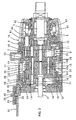
- FIG. 1 is a sectional view showing an entire battery-powered driver drill 1 as a representative example of a power tool according to the embodiment of the present invention.
- FIGS.2 to 4 are sectional views each showing an essential part of the driver drill. Specifically, FIG. 2 shows the state in which a planetary gear reducing mechanism is shifted to first gear (low speed).
- FIG. 3 shows the state in which the planetary gear reducing mechanism is shifted to second gear (medium speed).
- FIG. 4 shows the state in which the planetary gear reducing mechanism is shifted to third gear (high speed). As shown in FIG.
- the driver drill 1 mainly includes a body 1A, a bit holding chuck 1C disposed in a front end region of the body 1A (on the right side as viewed in FIG.1 ) and a handgrip 1B that is connected to the body 1A and designed to be held by a user. Further, the handgrip 1B extends in a direction that intersects with a longitudinal direction of the body 1 A.
- a battery case 25 is mounted on the extending end of the handgrip 1B and houses a battery for powering a motor 3.
- the body 1 A mainly includes a housing 2 that houses the motor 3, a first gear case 5 having a multi-tier cylindrical shape and disposed in the front region of the housing 2 (on the right side as viewed in FIG. 1 ), and a second gear case 6 that is disposed forward of the first gear case 5 and rotatably supports a spindle 7.
- the housing 2, the first gear case 5 and the second gear case 6 are fixedly connected to each other.
- the body 1A is a feature that corresponds to the "tool body” according to the present invention.
- a planetary gear reducing mechanism 8 is disposed within the both gear cases 5, 6, and a clutch mechanism 9 is disposed in the front region of the second gear case 6.
- the planetary gear reducing mechanism 8 is a feature that corresponds to the "speed changing mechanism” according to the present invention.
- the planetary gear reducing mechanism 8 includes first to third carriers 10, 11, 12 disposed in series in the axial direction (longitudinal direction) and each supporting three or four planetary gears on the rear surface side.
- a planetary gear 13 of the first carrier 10 is engaged with a pinion 14 fitted on an output shaft 4 of the motor 3 and the third carrier 12 is integrally connected to the spindle 7, so that torque of the output shaft 4 can be reduced and transmitted to the spindle 7.
- the chuck 1C is mounted onto a tip end of the spindle 7 and detachably holds a tool bit such as a driver bit and a drill bit.
- An output shaft 15 of the first carrier 10 has a rear large-diameter gear 15a and a front small-diameter gear 15b.
- the planetary gears that engage with the large-diameter and small-diameter gears 15a, 15b are also formed by two gears having different diameters, a front small gear 16 and a rear large gear 17.
- Each of the small and large gears 16, 17 is coaxially supported onto the second carrier 11 in such a manner as to be independently rotatable.
- the small gear 16 and the large gear 17 engage with the large-diameter gear 15a and the small-diameter gear 15b of the output shaft 15, respectively. Therefore, internal gears in the second tier from the rear are also disposed in series as one set in the longitudinal direction.
- This internal gear set comprises a second internal gear 19 in which the small gear 16 revolves (in a first internal gear 18 in the first tier from the rear, the planetary gear 13 of the first carrier 10 revolves) and a third internal gear 20 in which the large gear 17 revolves. Further, the internal gears 18, 19, 20 have internal teeth on the inner circumference and engage with the planetary gears 13, 16, 17, respectively.
- the output shaft 15 of the first carrier 10 that has the large-diameter and small-diameter gears 15a, 15b is a feature that corresponds to the "sun gear” according to the present invention.
- the small- and large-diameter gears 15b, 15a are features that correspond to the "first sun gear of a first gear train” and the "second sun gear of a second gear train", respectively, according to the present invention.
- the small-diameter gear 15b, the large gear 17 that engages with the small-diameter gear 15b, and the third internal gear 20 that engages with the large gear 17 form the "first gear train" according to the present invention.
- the large-diameter gear 15a, the small gear 16 that engages with the large-diameter gear 15a, and the second internal gear 19 that engages with the small gear 16 form the "second gear train” according to the present invention.
- the third and second internal gears 20, 19 are features that correspond to the "first internal gear of the first gear train” and the "second internal gear of the second gear train", respectively, according to the present invention.
- the second and third internal gears 19, 20 have the same outside diameter as the first internal gear 18.
- the second and third internal gears 19, 20 are disposed between an inner wall 22 of the first gear case 5 and the first internal gear 18 such that they are locked against longitudinal movement and can rotate independently. Further, the same numbers of external teeth 23, 24 having the same shape are formed on the outer circumferential surface of the second and third internal gears 19, 20.
- a switching member in the form of a switching sleeve 26 is disposed on the outside of the second and third internal gears 19, 20.
- the switching sleeve 26 is fitted on the second and third internal gears 19, 20 in such a manner as to be rotatable and movable in the axial direction (longitudinal direction).
- Internal teeth 27 are formed on the inner circumferential surface of a front portion of the switching sleeve 26 over a predetermined region extending in the axial direction and can engage with the external teeth 23, 24 of the second and third internal gears 19, 20.
- external teeth 28 are formed on the outer circumferential surface of the front end portion of the switching sleeve 26.
- the switching sleeve 26 is prevented from rotating when the external teeth 28 engage with engagement teeth 29 formed in the inner circumferential surface of the first gear case 5 and extending in the axial direction, or when the large-diameter internal teeth 31 engage with engagement teeth 32 formed on the outer circumferential surface of the first internal gear 18, by the axial movement of the switching sleeve 26.
- the switching sleeve 26 is allowed to rotate when both of the external teeth 28 and the internal teeth 31 are disengaged from the respective engagement teeth 29, 32. Further, the first internal gear 18 is fixed to the first gear case 5.
- a connecting member in the form of a connecting sleeve 30 has a larger diameter than the switching sleeve 26 and is fitted on the rear portion of the switching sleeve 26 within the first gear case 5.
- Four protrusions are formed on the outer circumferential surface of the connecting sleeve 30 and extends in the axial direction, and recessed grooves (not shown) are formed in the inner surface of the first gear case 5. By engagement of the protrusions and the grooves, the connecting sleeve 30 is prevented from rotating and allowed to move in the axial direction.
- Four pins 33 are provided in the front end portion of the connecting sleeve 30 and spaced at regular intervals in the circumferential direction and extend toward the center in the radial direction.
- a ring groove 34 is formed generally in the middle of the outer circumferential surface of the switching sleeve 26 and extends in the circumferential direction. The extending end of each of the pins 33 is inserted into the ring groove 34, so that the switching sleeve 26 can move together with the connecting sleeve 30 in the axial direction, while being allowed to rotate. Specifically, the switching sleeve 26 is connected to the connecting sleeve 30 such that the switching sleeve 26 is allowed to move in the circumferential direction with respect to the connecting sleeve 30 and prevented from moving in the axial direction with respect to the connecting sleeve 30.
- the front end sliding position in which the front end of the connecting sleeve 30 contacts the inner wall 22 of the first gear case 5 is a first gear position (see FIG. 2 ).
- the front end sliding position and the first gear are features that correspond to the "first speed change position" and the "first speed", respectively, according to the present invention.
- the internal teeth 27 of the switching sleeve 26 engage only with the external teeth 24 of the third internal gear 20, and the external teeth 28 engage with the engagement teeth 29 of the first gear case 5.
- the large-diameter internal teeth 31 are disengaged from the engagement teeth 32 of the first internal gear 18.
- the rear end sliding position in which the rear end of the switching sleeve 26 contacts the first internal gear 18 is a second gear position (see FIG. 3 ).
- the rear end sliding position and the second gear are features that correspond to the "second speed change position" and the "second speed", respectively, according to the present invention.
- the internal teeth 27 of the switching sleeve 26 engage only with the external teeth 23 of the second internal gear 19, and the large-diameter internal teeth 31 engage with the engagement teeth 32 of the first internal gear 18.
- the external teeth 28 are disengaged from the engagement teeth 29 of the first gear case 5.
- the internal teeth 27 of the switching sleeve 26 lie astride and engage with the external teeth 23 of the second internal gear 19 and the external teeth 24 of the third internal gear 20 at the same time.
- the external teeth 28 and the large-diameter internal teeth 31 are disengaged from the engagement teeth 29 of the first gear case 5 and the engagement teeth 32 of the first internal gear 18, respectively (see FIG. 4 ).
- the intermediate sliding position and the third gear are features that correspond to the "third speed change position" and the "third speed", respectively, according to the present invention.
- a connecting projection 36 is formed on the upper surface of the rear end portion of the connecting sleeve 30 and extends through a slit 35 formed in the rear end portion of the first gear case 5 and extending in the axial direction.
- the connecting projection 36 is connected to a sliding member in the form of a slide plate 37.
- the slide plate 37 is provided on the housing 2 in such a manner as to be slidable in the longitudinal direction.
- the connecting projection 36 is inserted into a recessed portion 38 formed in the underside of the slide plate 37. This connecting projection 36 is placed and supported between front and rear coil springs 39, so that the connecting projection 36 is connected to the slide plate 37.
- the connecting sleeve 30 and the switching sleeve 26 can be operated by the user from the outside of the housing 2 so as to be moved in the longitudinal direction. Specifically, the user holds an operating projection 40 formed on the upper surface of the slide plate 37 and moves the slide plate 37 in the longitudinal direction.
- the switching sleeve 26, the connecting sleeve 30 and the slide plate 37 form a switching means. This switching means is a feature that corresponds to the "speed changing part" according to the present invention.
- a fourth internal gear 21 placed in the third tier from the rear is rotatably disposed within the second gear case 6.
- a plurality of pins 41 extend through the second gear case 6 in the axial direction and contacts the front surface of the fourth internal gear 21.
- the pins 41 are biased rearward via a washer 44 by a coil spring 43.
- the coil spring 43 is disposed between the pins 41 and a spring holder 42 that is threadably mounted on the second gear case 6. Therefore, the fourth internal gear 21 is engaged with the pin 41 biased by the coil spring 43 and thereby prevented from rotating.
- a change ring 45 is mounted on the outside of the second gear case 6 and can be turned by the user to threadably move the spring holder 42 in the axial direction. By thus moving the spring holder 42 by turning the change ring 45, the biasing force of the coil spring 43 can be changed to adjust the clutch actuation torque in driver mode.
- the large gear 17 within the locked third internal gear 20 is caused to revolve, and the second carrier 11 is caused to rotate in synchronization with the revolution. Subsequently, the second carrier 11 is caused to rotate the third carrier 12 via the planetary gear 46 located in the next tier and thus rotate the spindle 7 that is integrally connected to the third carrier 12. In this manner, in the first gear position, torque is transmitted to the second carrier 11 via the large gear 17. At this time, the spindle 7 rotates at low speed, or a speed based on the speed reduction ratio that is defined by the numbers of the teeth of the small-diameter gear 15b of the output shaft 15 and the third internal gear 20.
- the connecting sleeve 30 and the switching sleeve 26 move to the intermediate position.
- the switching sleeve 26 is then engaged with both of the second internal gear 19 and the third internal gear 20 and disengaged from both of the engagement teeth 29, 32 of the first gear case 5 and the first internal gear 18. Therefore, the second and third internal gears 19, 20 are allowed to rotate and integrated with each other in the circumferential direction, so that the first carrier 10 and the second carrier 11 are directly connected.
- the motor 3 is driven in this state, the first carrier 10 and the second carrier 11 rotate at the same speed.
- Subsequent torque transmission from the second carrier 11 is the same as in the second gear position. However, in this position, speed reduction is not caused between the first carrier 10 and the second carrier 11, so that the spindle 7 rotates at high speed.
- rotation of the second and third internal gears 19, 20 can be individually controlled. Further, by provision of the switching means that connects the second internal gear 19 and the third internal gear 20 such that the internal gears can rotate together, three speeds can be realized simply by shifting the engagement between the second and third internal gears 19, 20 without sliding the internal gears 18 to 21. Therefore, the number of parts can be reduced as a whole, and thus the manufacturing costs and assembling labors can be reduced and reliable shifting can also be expected. Particularly, three speeds can be realized by provision of only one-tier gear set that includes the one carrier 11 and the two internal gears 19, 20 which support two front and rear planetary gears. Therefore, the number of gear sets can be reduced, and the construction can be effectively simplified.
- the switching means is formed by using the switching sleeve 26 which can be selectively placed in three sliding positions by operating the slide plate 37.
- the speed can be selected by simple longitudinal movement of the slide plate 37 (the switching sleeve 26), so that higher operability can be realized.
- the planetary gear reducing mechanism 8 is disposed in an earlier tier than the clutch mechanism 9 in terms of torque transmission. Therefor, a clutch actuation torque setting can be prevented from fluctuating due to the shifting operation of the planetary gear reducing mechanism 8. Thus, ease of use can also be effectively enhanced.
- the switching sleeve 26 is connected to the slide plate 37 via the connecting sleeve 30 that is elastically supported by the coil spring 39. With this construction, the switching sleeve 26 can smoothly engage with the second and third internal gears 19, 20, or the first gear case 5 and the first internal gear 18 by its sliding movement
- the third gear position in which the spindle 7 is rotated at high speed is located in an intermediate position in the direction of sliding operation of the slide plate 37.
- the first gear position in which the spindle 7 is rotated at low speed is located forward of the intermediate position
- the second gear position in which the spindle 7 is rotated at medium speed is located rearward of the intermediate position.
- the switching sleeve 26 when the switching sleeve 26 is slid to the front sliding position, the external teeth 28 in the form of the engagement portion formed on the outer circumferential surface of the front end portion of the switching sleeve 26 engage with the engagement teeth 29 of the first gear case 5, so that the third internal gear 20 is locked to the first gear case 5.
- the large-diameter internal teeth 31 in the form of the engagement portion formed on the inner circumferential surface of the rear end portion of the switching sleeve 26 engage with the engagement teeth 32 of the first internal gear 18, so that the third internal gear 20 is locked to the first gear case 5.
- the switching sleeve 26 can be connected to the connecting sleeve 30 by the pins 33 at a connecting point formed in the intermediate position of the switching sleeve 26 in the sliding direction.
- shifting operation can be smoothly performed without strongly pushing the switching sleeve 26.
- the switching means is provided on the three-tiered planetary gear reducing mechanism 8.
- the switching means can be applied if one-tier gear set is provided which is formed by the two internal gears 19, 20 and the carrier II for supporting the front and rear planetary gears. Therefore, a planetary gear reducing mechanism having a two-tier or even only one-tire gear set can also be applied.
- the output shaft 15 of the first carrier 10, or a sun gear having the large-diameter gear 15a and the small-diameter gear 15b may be provided, in place of the pinion 14, on the output shaft 4 of the motor 3.
- the driver drill 1 is explained as a representative example of the power tool, but the present invention can also be applied to other power tools, such as an electric driver and an electric drill, which perform a predetermined operation by rotating a tool bit about its axis.
Landscapes
- Engineering & Computer Science (AREA)
- Mechanical Engineering (AREA)
- Drilling And Boring (AREA)
- Structure Of Transmissions (AREA)
- Portable Power Tools In General (AREA)
Claims (4)
- Outil électrique, comprenant :un moteur (3) qui est logé dans un corps d'outil (1A),une broche (7) qui est montée à rotation dans une région d'extrémité avant du corps d'outil (1A),un mécanisme de changement de vitesse (8) qui est disposé entre un arbre de sortie (4) du moteur (3) et la broche (7) et sert à changer la vitesse de rotation de l'arbre de sortie (4) et à transmettre la vitesse de rotation à la broche (7), le mécanisme de changement de vitesse (8) comprenant :des premier et second trains d'engrenages (15b, 17, 20 ; 15a, 16, 19) ayant chacun un ensemble formé d'une roue solaire (15b ; 15a), qui est entraînée en rotation par l'arbre de sortie (4), d'une roue planétaire (17 ; 16), qui s'engage sur la roue solaire (15b ; 15a) et peut pivoter tout en tournant, et d'une roue dentée interne (20 ; 19), qui s'engage sur la roue planétaire (17 ; 16) et peut tourner via la roue solaire (15b ; 15a) ; etun support (11) qui est raccordé à la broche (7) et supporte à rotation la première roue planétaire (17) du premier train d'engrenages (15b, 17, 20) et la seconde roue planétaire (16) du second train d'engrenages (15a, 16, 19), etune partie de changement de vitesse (26, 30, 37) qui est à même d'être glissée dans la direction longitudinale du corps d'outil (1A) par un utilisateur depuis l'extérieur du corps d'outil (1A),la partie de changement de vitesse (26, 30, 37) étant à même d'être déplacée de la première à la troisième position de changement de vitesse, dans lequel, dans la première position de changement de vitesse, la partie de changement de vitesse (26, 30, 37) bloque la première roue dentée interne (20) du premier train d'engrenages (15b, 17, 20) sur le corps d'outil (1A) et empêche donc la première roue dentée interne (20) de tourner tout en permettant à la seconde roue dentée interne (19) du second train d'engrenages (15a, 16, 19) de tourner sans bloquer la seconde roue dentée interne (19) sur le corps d'outil (1A) ;dans la deuxième position de changement de vitesse, la partie de changement de vitesse (26, 30, 37) bloque la seconde roue dentée interne (19) du corps d'outil (1A) et empêche donc la seconde roue dentée interne (19) de tourner, tout en permettant à la première roue dentée interne (20) de tourner sans bloquer la première roue dentée interne (20) sur le corps d'outil (1A) ; etdans la troisième position de changement de vitesse, la partie de changement de vitesse (26, 30, 37) raccorde conjointement les première et seconde roues dentées internes (20 ; 19) et permet aux première et seconde roues dentées internes (20 ; 19) de tourner conjointement sans bloquer les première et seconde roues dentées internes (20 ; 19) sur le corps d'outil (1A), etlorsque la partie de changement de vitesse (26, 30, 37) est placée dans la première position de changement de vitesse, le support (11) est entraîné en rotation à une première vitesse prédéterminée qui est définie par un rapport de réduction de vitesse du premier train d'engrenages (15b, 17, 20),lorsque la partie de changement de vitesse (26, 30, 37) est placée dans la deuxième position de changement de vitesse, le support (11) est entraîné en rotation à une deuxième vitesse prédéterminée qui est définie par un rapport de réduction de vitesse du second train d'engrenages (15a, 16, 19) et est plus rapide que la première vitesse,lorsque la partie de changement de vitesse (26, 30, 37) est placée dans la troisième position de changement de vitesse, le support (11) est entraîné en rotation conjointement avec les première et seconde roues solaires (15a, 15b) à une troisième vitesse prédéterminée qui est plus rapide que la deuxième vitesse, etla première position de changement de vitesse est située sur un côté d'extrémité dans la direction de coulissement de la partie de changement de vitesse (26, 30, 37), la deuxième position de changement de vitesse est située sur l'autre côté d'extrémité et la troisième position de changement de vitesse est située dans une portion intermédiaire entre les première et deuxième positions de changement de vitesse.
- Outil électrique selon la revendication 1, dans lequel :la vitesse de rotation du support (11) est réglée de sorte que la différence de vitesse entre les première et deuxième vitesses est plus petite que la différence de vitesse entre les deuxième et troisième vitesses.
- Outil électrique selon la revendication 1 ou la revendication 2, dans lequel :la partie de changement de vitesse (26, 30, 37) comprend un élément coulissant (37) qui est disposé sur l'extérieur du corps d'outil (1A) et peut être glissé par l'utilisateur et un élément de commutation (26) qui est disposé sur l'extérieur des première et seconde roues dentées internes (20 ; 19) de manière à pouvoir tourner et à pouvoir se déplacer dans la direction axiale, l'élément de commutation (26) étant connecté à l'élément coulissant (37) de sorte que l'élément de commutation (16) soit autorisé à se déplacer dans la direction circonférentielle par rapport à l'élément coulissant (37) et empêché de se déplacer dans la direction axiale par rapport à l'élément coulissant (37) ; etdes portions d'engagement (28, 31) sont prévues sur les deux portions d'extrémité de l'élément de commutation (26) dans la direction de déplacement et peuvent s'engager sur le corps d'outil (A) ; et l'une ou l'autre des portions d'engagement (28, 31) s'engage sur le corps d'outil 1A), empêchant de la sorte la première roue dentée interne (20) ou la seconde roue dentée interne (19) de tourner ; etl'élément de commutation (26) est raccordé à l'élément coulissant (37) sur une saillie de raccordement (36) formée dans une position intermédiaire de l'élément de commutation (26) dans la direction de déplacement.
- Outil électrique selon l'une quelconque des revendications 1 à 3, dans lequel l'outil électrique est défini par un foret d'entraînement.
Applications Claiming Priority (1)
| Application Number | Priority Date | Filing Date | Title |
|---|---|---|---|
| JP2007010992A JP5030601B2 (ja) | 2007-01-22 | 2007-01-22 | 電動工具 |
Publications (2)
| Publication Number | Publication Date |
|---|---|
| EP1946895A1 EP1946895A1 (fr) | 2008-07-23 |
| EP1946895B1 true EP1946895B1 (fr) | 2013-01-02 |
Family
ID=39277305
Family Applications (1)
| Application Number | Title | Priority Date | Filing Date |
|---|---|---|---|
| EP08001012A Expired - Fee Related EP1946895B1 (fr) | 2007-01-22 | 2008-01-21 | Outil électrique |
Country Status (3)
| Country | Link |
|---|---|
| US (1) | US8485275B2 (fr) |
| EP (1) | EP1946895B1 (fr) |
| JP (1) | JP5030601B2 (fr) |
Families Citing this family (30)
| Publication number | Priority date | Publication date | Assignee | Title |
|---|---|---|---|---|
| US8075229B2 (en) * | 2007-06-26 | 2011-12-13 | Techtronic Power Tools Technology Limited | Multi-speed drill and chuck assembly |
| CN101637902B (zh) * | 2008-07-31 | 2012-07-25 | 苏州宝时得电动工具有限公司 | 变速工具 |
| DE102008041599A1 (de) * | 2008-08-27 | 2010-03-04 | Robert Bosch Gmbh | Schaltbares Getriebe in einer Handwerkzeugmaschine |
| JP4674640B2 (ja) * | 2009-01-27 | 2011-04-20 | パナソニック電工株式会社 | インパクト回転工具 |
| US8172004B2 (en) * | 2009-08-05 | 2012-05-08 | Techtronic Power Tools Technology Limited | Automatic transmission for a power tool |
| US8142326B2 (en) * | 2009-08-25 | 2012-03-27 | Power Network Industry Co., Ltd. | Multi-gear mechanism for power tools |
| DE102009029055A1 (de) * | 2009-09-01 | 2011-03-10 | Robert Bosch Gmbh | Bohr- und/oder Meißelhammervorrichtung |
| DE102009051844A1 (de) * | 2009-10-29 | 2011-05-05 | C. & E. Fein Gmbh | Handwerkzeug |
| DE102010002013B4 (de) * | 2010-02-17 | 2020-06-18 | Robert Bosch Gmbh | Aufsatz für eine Handwerkzeugmaschine |
| DE102010041172A1 (de) * | 2010-09-22 | 2012-03-22 | Robert Bosch Gmbh | Handgeführtes Elektrowerkzeug mit einem Getriebe |
| US8714888B2 (en) | 2010-10-25 | 2014-05-06 | Black & Decker Inc. | Power tool transmission |
| JP5693211B2 (ja) * | 2010-12-27 | 2015-04-01 | 株式会社マキタ | 作業工具 |
| DE102011004126A1 (de) * | 2011-02-15 | 2012-08-16 | Robert Bosch Gmbh | Handwerkzeugmaschine mit einem Untersetzungsgetriebe |
| JP5314716B2 (ja) * | 2011-02-22 | 2013-10-16 | パナソニック株式会社 | 電動工具 |
| JP5628079B2 (ja) * | 2011-04-05 | 2014-11-19 | 株式会社マキタ | 震動ドライバドリル |
| DE112011105222B4 (de) * | 2011-05-09 | 2018-08-23 | Zhengyang Technology Co., Ltd. | Vorrichtung zum automatischen Umschalten zwischen Vor- und Rückwärtsdrehung einer elektrischen Bohrmaschine |
| JP5744639B2 (ja) * | 2011-06-17 | 2015-07-08 | 株式会社マキタ | 電動工具 |
| US11059160B2 (en) | 2011-07-29 | 2021-07-13 | Black & Decker Inc. | Multispeed power tool |
| US9481080B2 (en) | 2011-07-29 | 2016-11-01 | Black & Decker Inc. | Multispeed power tool |
| US9233461B2 (en) | 2012-02-27 | 2016-01-12 | Black & Decker Inc. | Tool having multi-speed compound planetary transmission |
| CN103322129A (zh) * | 2013-06-28 | 2013-09-25 | 无锡麻德克斯精机有限公司 | 一种行星齿轮减速装置 |
| CN104493772B (zh) * | 2014-12-29 | 2017-01-18 | 绍兴环洲工具制造有限公司 | 变速头及螺丝刀 |
| JP6604536B2 (ja) * | 2015-08-04 | 2019-11-13 | パナソニックIpマネジメント株式会社 | 電動工具 |
| CN205437247U (zh) * | 2015-12-28 | 2016-08-10 | 南京德朔实业有限公司 | 扭力输出工具 |
| WO2018031566A1 (fr) * | 2016-08-08 | 2018-02-15 | HYTORC Division Unex Corporation | Appareil de serrage d'éléments de fixation filetés |
| DE102018204051A1 (de) * | 2018-03-16 | 2019-09-19 | Bühler Motor GmbH | Planetenradträger für ein Umlaufrädergetriebe und Baureihe von Umlaufrädergetrieben |
| US11813729B2 (en) | 2018-05-14 | 2023-11-14 | Black & Decker Inc. | Power tool with partition assembly between transmission and motor |
| US10971966B2 (en) | 2018-05-14 | 2021-04-06 | Black & Decker Inc. | Power tool with partition assembly between transmission and motor |
| EP3572190B1 (fr) * | 2018-05-23 | 2022-04-06 | Black & Decker Inc. | Outil électrique multivitesse |
| US11964375B2 (en) | 2019-11-27 | 2024-04-23 | Black & Dekcer Inc. | Power tool with multispeed transmission |
Family Cites Families (20)
| Publication number | Priority date | Publication date | Assignee | Title |
|---|---|---|---|---|
| DE3525208A1 (de) | 1984-07-16 | 1986-01-23 | Japan Strage Battery Co. Ltd., Kyoto | Untersetzungsgetriebe |
| JPH06100251B2 (ja) | 1985-01-14 | 1994-12-12 | 株式会社小松製作所 | 遊星歯車式変速装置 |
| JPS62224584A (ja) | 1986-03-25 | 1987-10-02 | 松下電工株式会社 | 電動工具 |
| US4926713A (en) | 1989-03-15 | 1990-05-22 | H.V.T. Technology Ltd. | Multiple gear-ratio automatic transmission |
| JPH0395407U (fr) * | 1990-01-18 | 1991-09-30 | ||
| US5339908A (en) | 1990-10-02 | 1994-08-23 | Ryobi Limited | Power tool |
| US5550416A (en) | 1995-02-09 | 1996-08-27 | Fanchang; We C. | Control mechanism of revolving speed of an electric tool |
| DE19900766A1 (de) | 1998-01-17 | 1999-07-22 | Weck Manfred Prof Dr Ing Dr In | Schaltgetriebe für Fahrzeuge, vorzugsweise Kraftfahrzeuge |
| DE19902187A1 (de) | 1998-03-04 | 1999-09-16 | Scintilla Ag | Gangumschaltbares Planetengetriebe |
| JP3872897B2 (ja) | 1998-06-17 | 2007-01-24 | 株式会社マキタ | 電動工具 |
| US6142242A (en) | 1999-02-15 | 2000-11-07 | Makita Corporation | Percussion driver drill, and a changeover mechanism for changing over a plurality of operating modes of an apparatus |
| US6729812B2 (en) | 1999-12-06 | 2004-05-04 | Theodore G. Yaksich | Power driver having geared tool holder |
| US6422969B1 (en) | 2000-08-14 | 2002-07-23 | General Motors Corporation | Powertrain with a six speed planetary transmission having three planetary gear sets |
| CN2441614Y (zh) | 2000-09-26 | 2001-08-08 | 上海星特浩企业有限公司 | 电动工具用三速变速齿轮箱 |
| US6431289B1 (en) | 2001-01-23 | 2002-08-13 | Black & Decker Inc. | Multi-speed power tool transmission |
| US6676557B2 (en) | 2001-01-23 | 2004-01-13 | Black & Decker Inc. | First stage clutch |
| TW572152U (en) * | 2002-11-08 | 2004-01-11 | Power Network Industry Co Ltd | Three-stage gearshift mechanism |
| US6655470B1 (en) | 2002-12-23 | 2003-12-02 | Power Network Industry Co., Ltd. | Speed changing mechanism for tools |
| JP3963323B2 (ja) * | 2003-02-07 | 2007-08-22 | 株式会社マキタ | 電動工具 |
| US6796921B1 (en) * | 2003-05-30 | 2004-09-28 | One World Technologies Limited | Three speed rotary power tool |
-
2007
- 2007-01-22 JP JP2007010992A patent/JP5030601B2/ja not_active Expired - Fee Related
-
2008
- 2008-01-21 EP EP08001012A patent/EP1946895B1/fr not_active Expired - Fee Related
- 2008-01-22 US US12/010,171 patent/US8485275B2/en not_active Expired - Fee Related
Also Published As
| Publication number | Publication date |
|---|---|
| JP2008173739A (ja) | 2008-07-31 |
| US20080173459A1 (en) | 2008-07-24 |
| EP1946895A1 (fr) | 2008-07-23 |
| US8485275B2 (en) | 2013-07-16 |
| JP5030601B2 (ja) | 2012-09-19 |
Similar Documents
| Publication | Publication Date | Title |
|---|---|---|
| EP1946895B1 (fr) | Outil électrique | |
| JP3963323B2 (ja) | 電動工具 | |
| EP2875906B1 (fr) | Transmission cycloïdale multivitesse | |
| EP1481768B1 (fr) | Outil rotatif motorisé à trois vitesses | |
| JP4674640B2 (ja) | インパクト回転工具 | |
| JP5117258B2 (ja) | 自動変速式動力工具 | |
| EP2614931B1 (fr) | Outil électrique avec couple d'embrayage | |
| EP1932608B1 (fr) | Foreuse/visseuse | |
| JP5628079B2 (ja) | 震動ドライバドリル | |
| JP5064780B2 (ja) | スクリュードライバ | |
| JP2009006476A (ja) | 多速度ドリル及びチャック組立体 | |
| US20070281822A1 (en) | Electric hand tool device | |
| US10513023B2 (en) | Power tool | |
| JP4053865B2 (ja) | 電動工具 | |
| JP5341429B2 (ja) | 電動工具 | |
| JPH0679509A (ja) | ドリル・チゼル装置 | |
| JP4063641B2 (ja) | 電動工具 | |
| JP2005254374A (ja) | インパクトドライバ | |
| CN201950239U (zh) | 具有可变扭矩离合器的钻 | |
| CN107471164B (zh) | 扭力输出工具 | |
| CN112719365A (zh) | 手持式电动工具及其变速装置 |
Legal Events
| Date | Code | Title | Description |
|---|---|---|---|
| PUAI | Public reference made under article 153(3) epc to a published international application that has entered the european phase |
Free format text: ORIGINAL CODE: 0009012 |
|
| AK | Designated contracting states |
Kind code of ref document: A1 Designated state(s): AT BE BG CH CY CZ DE DK EE ES FI FR GB GR HR HU IE IS IT LI LT LU LV MC MT NL NO PL PT RO SE SI SK TR |
|
| AX | Request for extension of the european patent |
Extension state: AL BA MK RS |
|
| 17P | Request for examination filed |
Effective date: 20090123 |
|
| 17Q | First examination report despatched |
Effective date: 20090304 |
|
| AKX | Designation fees paid |
Designated state(s): DE FR GB |
|
| GRAP | Despatch of communication of intention to grant a patent |
Free format text: ORIGINAL CODE: EPIDOSNIGR1 |
|
| GRAS | Grant fee paid |
Free format text: ORIGINAL CODE: EPIDOSNIGR3 |
|
| GRAA | (expected) grant |
Free format text: ORIGINAL CODE: 0009210 |
|
| AK | Designated contracting states |
Kind code of ref document: B1 Designated state(s): DE FR GB |
|
| REG | Reference to a national code |
Ref country code: GB Ref legal event code: FG4D |
|
| REG | Reference to a national code |
Ref country code: DE Ref legal event code: R096 Ref document number: 602008021252 Country of ref document: DE Effective date: 20130307 |
|
| PLBE | No opposition filed within time limit |
Free format text: ORIGINAL CODE: 0009261 |
|
| STAA | Information on the status of an ep patent application or granted ep patent |
Free format text: STATUS: NO OPPOSITION FILED WITHIN TIME LIMIT |
|
| 26N | No opposition filed |
Effective date: 20131003 |
|
| REG | Reference to a national code |
Ref country code: DE Ref legal event code: R097 Ref document number: 602008021252 Country of ref document: DE Effective date: 20131003 |
|
| REG | Reference to a national code |
Ref country code: FR Ref legal event code: PLFP Year of fee payment: 8 |
|
| PGFP | Annual fee paid to national office [announced via postgrant information from national office to epo] |
Ref country code: DE Payment date: 20150113 Year of fee payment: 8 |
|
| PGFP | Annual fee paid to national office [announced via postgrant information from national office to epo] |
Ref country code: FR Payment date: 20150108 Year of fee payment: 8 Ref country code: GB Payment date: 20150121 Year of fee payment: 8 |
|
| REG | Reference to a national code |
Ref country code: DE Ref legal event code: R119 Ref document number: 602008021252 Country of ref document: DE |
|
| GBPC | Gb: european patent ceased through non-payment of renewal fee |
Effective date: 20160121 |
|
| REG | Reference to a national code |
Ref country code: FR Ref legal event code: ST Effective date: 20160930 |
|
| PG25 | Lapsed in a contracting state [announced via postgrant information from national office to epo] |
Ref country code: DE Free format text: LAPSE BECAUSE OF NON-PAYMENT OF DUE FEES Effective date: 20160802 Ref country code: GB Free format text: LAPSE BECAUSE OF NON-PAYMENT OF DUE FEES Effective date: 20160121 |
|
| PG25 | Lapsed in a contracting state [announced via postgrant information from national office to epo] |
Ref country code: FR Free format text: LAPSE BECAUSE OF NON-PAYMENT OF DUE FEES Effective date: 20160201 |