EP1946710A1 - Chirurgisches Instrument zur Implantierung eines Drahtes, vorzugsweise in einen Knochen - Google Patents
Chirurgisches Instrument zur Implantierung eines Drahtes, vorzugsweise in einen Knochen Download PDFInfo
- Publication number
- EP1946710A1 EP1946710A1 EP07121002A EP07121002A EP1946710A1 EP 1946710 A1 EP1946710 A1 EP 1946710A1 EP 07121002 A EP07121002 A EP 07121002A EP 07121002 A EP07121002 A EP 07121002A EP 1946710 A1 EP1946710 A1 EP 1946710A1
- Authority
- EP
- European Patent Office
- Prior art keywords
- wire
- clamping
- surgical instrument
- receiving element
- surgical
- Prior art date
- Legal status (The legal status is an assumption and is not a legal conclusion. Google has not performed a legal analysis and makes no representation as to the accuracy of the status listed.)
- Granted
Links
- 210000000988 bone and bone Anatomy 0.000 title claims description 28
- 238000005452 bending Methods 0.000 claims description 12
- 230000015572 biosynthetic process Effects 0.000 claims description 3
- 230000006835 compression Effects 0.000 claims description 2
- 238000007906 compression Methods 0.000 claims description 2
- 230000008901 benefit Effects 0.000 description 6
- 208000010392 Bone Fractures Diseases 0.000 description 5
- 230000000694 effects Effects 0.000 description 5
- 238000003780 insertion Methods 0.000 description 5
- 230000037431 insertion Effects 0.000 description 5
- 239000002184 metal Substances 0.000 description 5
- 206010017076 Fracture Diseases 0.000 description 4
- 230000009471 action Effects 0.000 description 4
- 239000012634 fragment Substances 0.000 description 4
- 238000001746 injection moulding Methods 0.000 description 4
- 238000000034 method Methods 0.000 description 4
- 230000008569 process Effects 0.000 description 3
- 208000027418 Wounds and injury Diseases 0.000 description 2
- 238000002788 crimping Methods 0.000 description 2
- 230000006378 damage Effects 0.000 description 2
- 238000011161 development Methods 0.000 description 2
- 238000006073 displacement reaction Methods 0.000 description 2
- 238000005553 drilling Methods 0.000 description 2
- 208000014674 injury Diseases 0.000 description 2
- 238000003825 pressing Methods 0.000 description 2
- 230000008859 change Effects 0.000 description 1
- 238000005520 cutting process Methods 0.000 description 1
- 238000013461 design Methods 0.000 description 1
- 210000005069 ears Anatomy 0.000 description 1
- 230000003670 easy-to-clean Effects 0.000 description 1
- 238000002513 implantation Methods 0.000 description 1
- 238000004519 manufacturing process Methods 0.000 description 1
- 239000000463 material Substances 0.000 description 1
- 230000005012 migration Effects 0.000 description 1
- 238000013508 migration Methods 0.000 description 1
- 230000000399 orthopedic effect Effects 0.000 description 1
- 230000003068 static effect Effects 0.000 description 1
- 238000001356 surgical procedure Methods 0.000 description 1
- 230000004083 survival effect Effects 0.000 description 1
- 238000012549 training Methods 0.000 description 1
Images



Classifications
-
- A—HUMAN NECESSITIES
- A61—MEDICAL OR VETERINARY SCIENCE; HYGIENE
- A61B—DIAGNOSIS; SURGERY; IDENTIFICATION
- A61B17/00—Surgical instruments, devices or methods
- A61B17/56—Surgical instruments or methods for treatment of bones or joints; Devices specially adapted therefor
- A61B17/58—Surgical instruments or methods for treatment of bones or joints; Devices specially adapted therefor for osteosynthesis, e.g. bone plates, screws or setting implements
- A61B17/88—Osteosynthesis instruments; Methods or means for implanting or extracting internal or external fixation devices
- A61B17/8861—Apparatus for manipulating flexible wires or straps
-
- A—HUMAN NECESSITIES
- A61—MEDICAL OR VETERINARY SCIENCE; HYGIENE
- A61B—DIAGNOSIS; SURGERY; IDENTIFICATION
- A61B17/00—Surgical instruments, devices or methods
- A61B17/56—Surgical instruments or methods for treatment of bones or joints; Devices specially adapted therefor
- A61B17/58—Surgical instruments or methods for treatment of bones or joints; Devices specially adapted therefor for osteosynthesis, e.g. bone plates, screws or setting implements
- A61B17/88—Osteosynthesis instruments; Methods or means for implanting or extracting internal or external fixation devices
- A61B17/8863—Apparatus for shaping or cutting osteosynthesis equipment by medical personnel
-
- A—HUMAN NECESSITIES
- A61—MEDICAL OR VETERINARY SCIENCE; HYGIENE
- A61B—DIAGNOSIS; SURGERY; IDENTIFICATION
- A61B17/00—Surgical instruments, devices or methods
- A61B17/16—Instruments for performing osteoclasis; Drills or chisels for bones; Trepans
- A61B17/1697—Instruments for performing osteoclasis; Drills or chisels for bones; Trepans specially adapted for wire insertion
-
- A—HUMAN NECESSITIES
- A61—MEDICAL OR VETERINARY SCIENCE; HYGIENE
- A61B—DIAGNOSIS; SURGERY; IDENTIFICATION
- A61B17/00—Surgical instruments, devices or methods
- A61B17/56—Surgical instruments or methods for treatment of bones or joints; Devices specially adapted therefor
- A61B17/58—Surgical instruments or methods for treatment of bones or joints; Devices specially adapted therefor for osteosynthesis, e.g. bone plates, screws or setting implements
- A61B17/88—Osteosynthesis instruments; Methods or means for implanting or extracting internal or external fixation devices
- A61B17/8897—Guide wires or guide pins
-
- A—HUMAN NECESSITIES
- A61—MEDICAL OR VETERINARY SCIENCE; HYGIENE
- A61B—DIAGNOSIS; SURGERY; IDENTIFICATION
- A61B90/00—Instruments, implements or accessories specially adapted for surgery or diagnosis and not covered by any of the groups A61B1/00 - A61B50/00, e.g. for luxation treatment or for protecting wound edges
- A61B90/08—Accessories or related features not otherwise provided for
- A61B2090/0801—Prevention of accidental cutting or pricking
Definitions
- the invention relates to a surgical instrument.
- the invention relates to a surgical instrument for handling a straight or curved surgical wire for use in an intraoperative procedure.
- Surgical wires such as Kirschner wires (or K-wires) are commonly used to fix bone fractures.
- K-wires Surgical wires, such as Kirschner wires (or K-wires) are commonly used to fix bone fractures.
- a bore is created in the bone fragment to be fixed and in the adjacent bone in a first step.
- the wire is passed through these two holes and positioned, for example, by twisting or connecting with other fixing elements such that the fracture is fixed and thus in this way a growing together of the bone is possible again.
- aids which make it possible to first bend the wire at its free end, so that an introduction into a bore which is provided in the bone, is possible.
- Corresponding bending tools are provided for this purpose.
- Other tools are used to insert the wire into the two holes. If the wire has been passed through both holes, it is known to use a pair of wire tongs, with this bend off the protruding end of the bone and, if necessary, cut off. As a result, the wire is fixed at its near-bone end in such a pair of wire-cutters and accordingly bent upon further compression of the handles (Zuggurtungs-Osteosynthesis).
- the most commonly used wire sizes are between 0.8 and 2 mm.
- the use of the appropriate diameter depends very much on the stress of the individual bone fragments. Heavily loaded areas, such as the hips, require stronger diameters for wire fixation, whereas lower weighted bone fragments require correspondingly thinner wire sizes.
- the insertion of the wire into a bore provided in a bone is usually done with commercially available surgical instruments such as forceps.
- the surgeon grips the surgical wire with the jaws of the forceps and introduces the wire into the bore. If he has almost reached the bone with the jaws, the forceps must be loosened and re-clamp the wire at another, spaced from the bone point.
- the clamping force it is possible that by advancing the forceps in the direction of the bone, the wire is inserted further into the bore.
- Kirschner wire for example a Kirschner wire (K-wire)
- K-wire Kirschner wire
- commercial surgical instruments are known. They are pliers-like and designed in such a way that the wire is clamped between two jaws.
- the jaws are tongs connected to handle members, so that a clamping force is exerted on the wire by squeezing the handle parts, which form the handle member.
- the jaws themselves are usually flat, so it is not absolutely necessary to have an exact one Position the jaws to effect propulsion within the bore in the bone.
- US 5116340 A (SONGER ROBERT J (US); SONGER MATTHEW N (US)) 26.05.1992 shows a forceps-type surgical securing instrument having two jaws movable relative to each other for generating a clamping force, the jaws having opposed receiving means for crimping surgical wires.
- WO 96/39976 A (BURKE DENNIS W (US)) 19.12.1996 shows a forceps-shaped instrument for tightening and crimping surgical wire in orthopedic surgery, wherein the wire is guided in receiving devices of the jaws.
- US 5314431 A (GRAZIANO THOMAS A) 24.05.1994 shows a forceps-shaped instrument for bending overhanging surgical wire, the jaws of which have an angled receiving device for the surgical wire.
- the invention has for its object to offer a surgical instrument for improved handling of a surgical wire.
- the surgical instrument should be suitable for professionally introducing a surgical wire into an already provided bore within a bone.
- a surgical instrument which essentially consists of a receiving element at least for receiving the to be applied wire, a clamping part, at least for clamping the wire and a handle member for holding the surgical instrument.
- the surgical instrument provides that the gripping element consists of two gripping parts, wherein the receiving element comprises the first grip part and the clamping part comprises the second grip part, the receiving element comprises a recess for at least partial support of the wire and the clamping part rotatably via a bearing on the receiving element is mounted and comprises a clamping element which engages in the recess and is configured such that by compressing the handle parts, the clamping member presses the wire against the support.
- a first step for wire osteosynthesis in intraoperative fracture treatment in which the bone fragments are connected to each other with wires, usually so-called Kirschner wires or K-wires, it is necessary to first bend the free end of the wire.
- wires usually so-called Kirschner wires or K-wires
- angles between 5 and 25 degrees are provided to allow insertion into a bore which has been placed within a bone.
- it is also provided initially to completely dispense with a bend, so that the surgical wire to be implanted is completely stretched and dimensioned in its length such that it is completely arranged in the surgical instrument according to the invention. Thus, no free end of the wire protrudes from the instrument.
- the invention thus goes the way not to use a forceps trained surgical instrument, but initially to provide a receiving element that preferably completely absorbs the surgical wire to be applied.
- a complete recording takes place in such a way that within the receiving element at least in a partial region a recess is present, in which a part of the elongated surgical wire is received.
- This gives the possibility that within the Receiving element is mounted to be applied surgical wire, in such a way that it can not change its corresponding position within the receiving element.
- the wire to be applied would ultimately be arranged freely between the clamping jaws, with the clamping jaws at least partially embracing the wire to be applied when the forceps-like instrument is pressed.
- the remaining part of the surgical wire is free and open. There is a considerable risk of injury in the operation of such training.
- the further essential advantage of the invention is that a movably mounted clamping part is provided relative to the receiving element which is fixed per se and which also provides means for receiving the surgical wire to be applied.
- the clamping part is designed such that it likewise comprises a grip part of the entire grip element and clamping elements are provided on the end opposite the grip part, which are designed to clamp the wire inside the receiving element.
- the relation of the clamping member and receiving member is configured such that by squeezing the handle members with one hand, a clamping action of the surgical wire within the receiving member is achieved so as to allow advancement of the wire within the bore. If at least one grip part, be it that of the clamping part or that of the receiving element relieved again, then the clamping part opens and the clamping action is reduced. This allows the surgeon to further remove the surgical instrument from the bone and retain the surgical wire in its already inserted position. The reason for this is that the static friction in the bore with respect to the wire is greater than that within the receiving element. This in turn releases more wire from the surgical instrument so that further implantation of the wire within the bore is possible.
- an essential feature of this invention is that the surgical instrument for applying a surgical wire can be used with one hand. It is sufficient that the receiving element is held in the hand and the clamping part for this purpose can be moved up and down relative to the fingers or the hand, so that a clamping effect on the one hand, on the other hand, the release of the wire is also achieved.
- the inventive surgical instrument consists of two components, namely the receiving element for receiving the wire to be applied and the clamping part for clamping the wire. These two parts are coupled with each other like a pliers.
- the receiving element on pins which are provided as a bearing for the connection of the clamping part.
- the clamping part is preferably designed such that it has eye-like openings, which are such that the clamping part is clipped onto the pins which are arranged on the receiving element and is pivotable about these pins.
- receiving element and pin are formed as an integral part, so that it is possible to produce the receiving element in a single injection molding process and in a further injection molding process, the clamping part.
- the clamping part itself is designed such that with respect to the longitudinal extent of the clamping part, the larger part is formed by a handle part. Moving away from the bearing (away from the grip part), the clamping surface is arranged, which preferably has a corresponding recess which is adapted to the diameter of the surgical wire to be applied. Clamping part and clamping surface preferably form an integral part, so that here also a manufacture in a single injection molding process is possible.
- a further development provides that the clamping surfaces of the clamping part are occupied by a metal element. Either the metal element which surrounds the clamping surface can be subsequently applied or it is already incorporated in the said injection molding process. By this metal element, the clamping force can be further increased and the wear occurring in this area can be reduced.
- a further embodiment provides that the clamping surface is profiled.
- the clamping surface can be corrugated, with the aim of increasing the frictional force between the wire to be clamped and the clamping surface.
- it may be provided to provide a profile, for example a notch, in the direction of the longitudinal extent of the wire so that the wire to be clamped works into the notch during the clamping process and is additionally clamped there.
- the notches can have different configurations.
- a further advantageous embodiment also provides that in the region of the recess in the receiving element also additional clamping or guide means are provided, which are adapted to receive the surgical wire to be applied.
- the recess for example in the form of a throat, is designed such that it can receive surgical wires in different diameters.
- the surgical instrument according to the invention is suitable for receiving and applying surgical wires, for example Kirschner wires of a small diameter, for example 0.8 mm to 2 mm, in a single device.
- surgical wires for example Kirschner wires of a small diameter, for example 0.8 mm to 2 mm
- the invention is not limited to the inclusion of these specified diameter. Rather, the scope of protection with respect to wires extends to such sizes and cross-sections as are used to fix bone. For this, many different diameters but also different cross sections are suitable.
- a development of the invention provides that also bending devices are provided in the receiving element. These bending devices are designed such that, for example, a free end of a surgical wire can be bent accordingly, so that the bent part to the rest of the elongated part occupies a defined angle. A likewise provided in the receiving element control device in the formation of a teaching can be used to control and measuring the angle generated.
- a preferred embodiment of the instrument provides that the entire instrument is made of metal. Because of this choice of material it is sterilizable.
- the product is made of plastic. So it can be used as a disposable product.
- the clamping area is metallized in a plastic version or provided with a metal plate.
- an auxiliary device which has the property that the two clamping parts can only be compressed when the surgical wire does not project beyond the free end of the surgical instrument on the handle side.
- a tab-like formation which extends from the clamping part in the direction of the free end of the receiving element, is designed such that in the compressed state of the surgical instrument, this free tab also covers the free end of the receiving element. This also covers the free end of the hole in which the wire is routed for the application and thus prevents the wire from unintentionally emerging on the handle side. As a result, a survival of the surgical wire on the handle side away is not possible and excluded injury to the hand of the surgeon.
- Fig. 1 a perspective view of a surgical instrument according to the invention
- Fig. 2 a perspective view of a surgical instrument according to the invention
- Fig. 3 a schematic representation of the clamping principle of the surgical instrument according to the Fig. 1 and 2 ;
- Fig. 4 a section through the surgical instrument according to Fig. 1 or 2 , being opposite Fig. 1 or 2 a surgical wire is received, but not clamped;
- Fig. 5 a section through the surgical instrument according to Fig. 1 or 2 , being opposite Fig. 1 a surgical wire is received which is clamped;
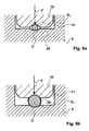
- Fig. 6 a and b is a schematic representation of a section through the surgical instrument according to Fig. 5 along a line VI-VI showing the clamping effect of different diameters of surgical wires;
- Fig. 7 a and b a representation of the operation of the provided in the receiving element bending device
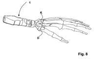
- Fig. 8 a schematic representation of the application of the surgical instrument according to the preceding figures.
- Fig. 1 and 2 show an overall perspective view of the inventive surgical instrument 1 for handling and implementation of a surgical wire, preferably a Kirschnerdrahts.
- the wire is in the embodiment shown here in the Fig. 1 and 2 Not shown.
- the surgical instrument 1 has two components, namely a receiving element 2 and a clamping part 3.
- the surgical instrument itself comprises a handle element 4, with which the surgical instrument can be operated by one hand.
- the receiving element 2 has essentially three functional areas.
- the first functional area is that of the grip element 4 and is formed by a grip part 5.
- a bearing 6 is provided on the handle part 5, wherein a guide and positioning element 7 adjoins the bearing 6 in turn.
- the bearing 6 comprises pins 29 which cooperate with a bearing element 9 of the clamping part 2.
- the clamping part 3 also has three functional areas.
- the first functional area is that of the grip element 4 and is formed by a grip part 8.
- a bearing element 9, which cooperates with the bearing 6 of the receiving element 2 adjoins the grip part 8.
- a clamping element 10 comprising the clamping part is provided on the bearing element 9.
- Both components namely the receiving element 2 and the clamping part 3 are formed as one-piece parts and form by cooperation on the bearing 6 and the bearing element 9, the surgical instrument. 1
- Fig. 3 the principle of the inventive surgical instrument 1 is shown.
- the receiving element 2 of the wire to be applied is stored.
- the clamping part 3 is coupled via bearings 6, 9 with the receiving element.
- the clamping part 3 has on its side facing away from the handle part 8, the clamping element 10, which performs a pivoting in the direction of arrow 13 by pivoting the clamping member 3 in the direction of arrow 12.
- the clamping element 10 penetrates a provided in the receiving element 2 recess 11.
- the clamping of the wire is fixed in and against the arrow 14. In this situation, which is achieved in that the two handle parts 5, 8 are compressed in the direction of arrow 19, the wire can be applied.
- Fig. 4 shows that the wire D has been inserted into the receiving element 2.
- the wire D is when inserted into the surgical instrument 1 in the direction of arrow 15 on the guiding and positioning element 7, which has a bore 16, inserted and pushed to a stop 17, which is provided in the region of the handle member 4. So that the wire D moves to the stop 17, the grip element 4 is slightly compressed, so that no clamping takes place.
- An alternative to the insertion of the wire D is that it is rearward, i. is introduced opposite to the guiding and positioning element 7 until the one end of the wire D is completely positioned within the receiving element 2 and the grip element 4 is compressible.
- the surgical wire to be applied can also be designed bent in its initial region 18, as it is in Fig. 4 is shown as an example.
- the two grip parts 4 and 5 To insert the surgical wire D into the receiving element 2, it is necessary for the two grip parts 4 and 5 to be spaced apart from one another in such a way that the clamping element 10 does not come to rest against the outer circumference D u . In this situation, no clamping action, caused by the clamping part 3, a.
- the in Fig. 5 situation can be achieved.
- a force F arises perpendicular to the longitudinal extent of the wire D and the wire D is thus pressed against the inner wall of the bore 16 of the receiving element 2 and clamped there, so that a displacement of the wire D in and against the arrow 14 is no longer possible , With this clamping adjustment of the wire D can be applied.
- the popping of the two handle parts 5 and 8 is in a particularly preferred embodiment by a spring element 27, as shown in the Fig. 1, 2 . 4 and 5 is shown supported.
- a spring element 27 As shown in the Fig. 1, 2 . 4 and 5 is shown supported.
- Fig. 6 a and b is a schematic section through the in Fig. 5 shown surgical instrument 1 shown.
- a clamping action is shown, which is caused by the fact that the clamping element 10 presses against the outer circumference D u of the wire D and thus presses the wire D against the receiving element 2. It acts a clamping force F, as in Fig. 6 a and b is shown.
- the clamping parts 10 and also a part of the recess 11 are designed such that different diameters of surgical wires D can be accommodated.
- Fig. 6a It is shown how a surgical wire D is accommodated with a small diameter and a corresponding clamping force F can be generated.
- Fig. 6b a surgical wire D is shown in which the diameter of the wire D is considerably larger.
- the respectively illustrated clamping surfaces 28 of the clamping element 10 may have differently shaped profiles. Regardless of the corresponding diameter of the respective wire D, the required clamping force F can still be displayed. All profiles have the property that the friction and / or the clamping force between the wire and the clamping element 10 is increased. Thus, it is possible to apply different diameters of different wires with one and the same surgical instrument 1.
- the receiving element 2 has in a further preferred embodiment, a device 22 ( Fig. 7a ).
- a device 22 ( Fig. 7a ).
- This comprises a bore 23, in which the wire to be processed D is inserted in the direction of arrow 24.
- a force F B acts on the outer circumference of the wire and thus causes the bend.
- this means 22 serves to bend the free end of the surgical wire D to facilitate insertion into a bore within a bone.
- a control area 25 is provided.
- This control area 25 is characterized by the fact that it has different segments for the control of the bending angle.
- a control gauge 26 is shown in which the wire D, as in Fig. 7b represented in the control gauge 26 is inserted. If the outer circumference of the wire D abuts the contour of the control gauge 26, the defined angle, in this case 20 degrees, is reached. More control ears can be provided.
- the inventive surgical instrument 1 thus has many advantages.
- One of the main advantages is that it is operated with one hand due to the grip element 4 and its configuration.
- the grip element 4 thus becomes the extended arm of the surgeon.
- the surgical instrument is easy to disassemble and therefore easy to clean and sterilize accordingly.
- the further embodiments have preferred bending devices, by means of which the free end of the wire can be correspondingly provided with an insertion angle.
- One and the same surgical instrument is suitable for receiving surgical wires, in particular Kirschner wires.
Landscapes
- Health & Medical Sciences (AREA)
- Life Sciences & Earth Sciences (AREA)
- Orthopedic Medicine & Surgery (AREA)
- Surgery (AREA)
- Medical Informatics (AREA)
- Engineering & Computer Science (AREA)
- Biomedical Technology (AREA)
- Heart & Thoracic Surgery (AREA)
- Nuclear Medicine, Radiotherapy & Molecular Imaging (AREA)
- Molecular Biology (AREA)
- Animal Behavior & Ethology (AREA)
- General Health & Medical Sciences (AREA)
- Public Health (AREA)
- Veterinary Medicine (AREA)
- Surgical Instruments (AREA)
- Prostheses (AREA)
- Dental Prosthetics (AREA)
Abstract
Description
- Die Erfindung betrifft ein chirurgisches Instrument. Insbesondere betrifft die Erfindung ein chirurgisches Instrument zur Handhabung eines geraden oder gebogenen, chirurgischen Drahtes für die Anwendung bei einem intraoperativen Eingriff.
- Chirurgische Drähte, beispielsweise Kirschnerdrähte (oder K-Drähte) werden in der Regel zur Fixierung von Knochenfrakturen verwendet. Zur Fixierung wird in einem ersten Schritt jeweils eine Bohrung in dem zu fixierenden Knochenfragment und in dem benachbarten Knochen erstellt. In einem weiteren Schritt wird der Draht durch diese beiden Bohrungen hindurchgeführt und beispielsweise durch Verdrehen oder Verbinden mit weiteren Fixierelementen derart positioniert, dass die Fraktur fixiert ist und so auf diese Weise ein Zusammenwachsen des Knochens wieder möglich ist.
- Zur Durchführung dieses Vorgangs sind unterschiedliche Werkzeuge notwendig. Zum einen sind Hilfsmittel vorgesehen, die es ermöglichen, zunächst den Draht an seinem freien Ende zu biegen, damit eine Einführung in eine Bohrung, die in dem Knochen vorgesehen ist, möglich ist. Entsprechende Biegewerkzeuge sind hierfür vorgesehen. Weitere Hilfswerkzeuge dienen dazu, den Draht in die beiden Bohrung einzuführen. Ist der Draht durch beide Bohrungen geführt worden, ist es bekannt, eine Drahtzange zu verwenden, mit dieser das aus dem Knochen herausragende Ende abzubiegen und gegebenenfalls abzuschneiden ist. Dadurch wird der Draht an seinem knochennahen Ende in einer solchen Drahtzange fixiert und beim weiteren Zusammendrücken der Handgriffe entsprechend gebogen (Zuggurtungs-Osteosynthese). Bei der klassischen Zuggurtungs-Osteosynthese wird das aus dem Knochen herausragende Ende des Kirschnerdrahtes dabei auf eine bestimmte Länge gekürzt und danach umgebogen. Durch die Umbiegung und das Hereindrücken des Drahtendes in den Knochen wird das Wandern des Drahtes im Knochen sowie die Rotation des Drahts um seine Längsachse verhindert. Sofern Knochenplatten zusätzlich zur Stützung der Fraktur verwendet werden, sind weitere Instrumente wie Schneidzangen, Biegezangen und ähnliches, zu verwenden.
- Die am häufigsten verwendeten Drahtstärken liegen zwischen 0,8 und 2 mm. Die Verwendung der entsprechenden Durchmesser hängt sehr stark von der Beanspruchung der einzelnen Knochenfragmente ab. Stark belastete Bereiche, wie beispielsweise die Hüfte, bedürfen zur Drahtfixierung stärkere Durchmesser, wohingegen bei weniger stark belastete Knochenfragmente entsprechend dünnere Drahtstärken Anwendung finden.
- Das Einführen des Drahtes in eine Bohrung, die in einem Knochen vorgesehen ist, erfolgt in der Regel mit handelsüblichen chirurgischen Instrumenten, wie beispielsweise einer Zange. Hierzu greift der Operateur den chirurgischen Draht mit den Klemmbacken der Zange und führt den Draht in die Bohrung ein. Hat er mit den Klemmbacken nahezu die Knochenaussenwahndung erreicht, so ist die Zange zu lösen und der Draht an einer weiteren, von dem Knochen beabstandeten Stelle erneut zu klemmen. Durch Aufbringen der Klemmkraft ist es möglich, dass durch Vorschieben der Zange in Richtung des Knochens der Draht weiter in die Bohrung eingeführt wird.
- Zum Einführen des Drahtes, beispielsweise eines Kirschnerdrahtes (K-Draht) sind handelsübliche chirurgische Instrumente bekannt. Sie sind zangenartig ausgebildet und in der Art gestaltet, dass der Draht zwischen zwei Klemmbacken geklemmt wird. Die Klemmbacken sind zangenartig mit Griffelementen verbunden, so dass durch Zusammendrücken der Griffteile, die das Griffelement bilden, eine Klemmkraft auf den Draht ausgeübt wird. Die Klemmbacken selbst sind in der Regel flach ausgebildet, so dass es nicht unbedingt notwendig ist, eine exakte Positionierung der Klemmbacken vorzunehmen, um einen Vortrieb innerhalb der Bohrung in dem Knochen zu bewirken.
-
DE 102004033633 A (STRYKER LEIBINGER GMBH & CO KG (DE)) 16.02.2006 zeigt ein chirurgisches Instrument zur Handhabung eines gebogenen chirurgischen Drahtes, mit zwei zur Erzeugung einer Klemmkraft relativ zueinander beweglichen Backen, wobei wenigstens eine der Backen eine Drahtaufnahme-Einrichtung aufweist. -
US 5116340 A (SONGER ROBERT J (US); SONGER MATTHEW N (US)) 26.05.1992 zeigt ein zangenförmiges chirurgisches -Sicherungsinstrument mit zwei zur Erzeugung einer Klemmkraft relativ zueinander beweglichen Backen, wobei die Backen entgegengesetzte Aufnahmevorrichtungen zum Crimpen chirurgischer Drähte aufweist. -
WO 96/39976 A -
US 5314431 A (GRAZIANO THOMAS A) 24.05.1994 zeigt ein zangenförmiges Instrument zum Umbiegen von überstehendem chirurgischen Draht, dessen Klemmbacken eine gewinkelte Aufnahmevorrichtung für den chirurgischen Draht aufweisen. -
DE 202005006132U (INTERCUS GMBH (DE)) 28.07.2005 zeigt ein Zielgerät von Kirschnerdrähten, wobei an einer Platte, an der ein Haltegriff angeordnet ist, wenigstens zwei Führungshülsen so zueinander angeordnet sind, dass sich die Achsen ausserhalb einer Fraktur kreuzen. - Der Erfindung liegt die Aufgabe zugrunde, ein chirurgisches Instrument zur verbesserten Handhabung eines chirurgischen Drahtes anzubieten. Insbesondere soll das chirurgische Instrument dafür geeignet sein, um einen chirurgischen Draht in eine bereits vorgesehene Bohrung innerhalb eines Knochens fachgerecht einzuführen.
- Diese Aufgabe wird gelöst durch ein chirurgisches Instrument, was im Wesentlichen aus einem Aufnahmeelement zumindest zur Aufnahme des zu applizierenden Drahtes, einem Klemmteil, zumindest zum Klemmen des Drahtes und einem Griffelement zum Halten des chirurgischen Instruments besteht. Erfindungsgemäss sieht das chirurgische Instrument vor, dass das Griffelement aus zwei Griffteilen besteht, wobei das Aufnahmeelement das erste Griffteil und das Klemmteil das zweite Griffteil umfasst, das Aufnahmeelement eine Ausnehmung zur zumindest teilweisen Auflage des Drahtes umfasst und das Klemmteil drehbeweglich über ein Lager an dem Aufnahmeelement gelagert ist und ein Klemmelement umfasst, das in die Ausnehmung eingreift und derart ausgestaltet ist, dass durch Zusammendrücken der Griffteile das Klemmteil den Draht gegen die Auflage drückt.
- In einem ersten Schritt zur Drahtosteosynthese bei einer intraoperativen Frakturbehandlung, bei denen die Knochenfragmente mit Drähten, meistens so genannten Kirschnerdrähten oder K-Drähten, miteinander verbunden werden, ist es notwendig, das freie Ende des Drahts zunächst zu biegen. In der Regel sind Winkel zwischen 5 und 25 Grad vorgesehen, um ein Einführen in eine Bohrung, die innerhalb eines Knochens angebracht worden ist, zu ermöglichen. Alternativ ist auch vorgesehen, zunächst auf eine Biegung vollständig zu verzichten, so dass der zu implantierende chirurgische Draht vollständig gestreckt ist und derart in seiner Länge bemessen ist, dass er vollständig in dem erfindungsgemässen chirurgischen Instrument angeordnet ist. Damit ragt kein freies Ende des Drahtes aus dem Instrument heraus.
- Die Erfindung geht somit den Weg, nicht ein zangenartig ausgebildetes chirurgisches Instrument zu verwenden, sondern zunächst ein Aufnahmeelement bereit zu stellen, das den zu applizierenden chirurgischen Draht vorzugsweise vollständig aufnimmt. Eine vollständige Aufnahme erfolgt in der Art, dass innerhalb des Aufnahmeelements zumindest in einem Teilbereich eine Ausnehmung vorhanden ist, in der ein Teil des langgestreckten chirurgischen Drahtes aufgenommen ist. Dadurch wird die Möglichkeit gegeben, dass innerhalb des Aufnahmeelements der zu applizierende chirurgische Draht gelagert ist, und zwar in der Art, dass dieser seine entsprechende Position innerhalb des Aufnahmeelements nicht verändern kann. Bei einer zangenartigen Ausbildung hingegen wäre der zu applizierende Draht letztendlich frei zwischen den Klemmbacken angeordnet, wobei beim Zudrücken des zangenartigen Instruments die Klemmbacken zumindest teilweise den zu applizierenden Draht umfassen. Der übrige Teil des chirurgischen Drahtes ist frei und offen zugänglich. Es besteht bei der Bedienung einer solchen Ausbildung eine erhebliche Verletzungsgefahr.
- Der weitere wesentliche Vorteil der Erfindung besteht darin, dass relativ zu dem an sich feststehenden Aufnahmeelement, das auch Mittel bereitstellt, den zu applizierenden chirurgischen Draht aufzunehmen, ein beweglich gelagertes Klemmteil vorgesehen ist. Das Klemmteil ist derart ausgebildet, dass es ebenfalls einen Griffteil des gesamten Griffelements umfasst und auf dem dem Griffteil gegenüberliegenden Ende Klemmelemente vorgesehen sind, die zum Klemmen des Drahtes innerhalb des Aufnahmeelements ausgebildet sind.
- Die Relation von Klemmteil und Aufnahmeelement ist derart ausgestaltet, dass durch Zusammendrücken der Griffteile mit einer Hand eine Klemmwirkung des chirurgischen Drahtes innerhalb des Aufnahmeelements erreicht wird, so dass ein Vorantreiben des Drahtes innerhalb der Bohrung ermöglicht wird. Wird zumindest ein Griffteil, sei es das des Klemmteils oder das des Aufnahmeelements wieder entlastet, so öffnet sich das Klemmteil und die Klemmwirkung reduziert sich. Dadurch ist es möglich, dass der Chirurg das chirurgische Instrument weiter von dem Knochen entfernt und der chirurgische Draht aber in seiner bereits eingeführten Position verharrt. Grund hierfür ist, dass die Haftreibung in der Bohrung in Bezug zu dem Draht grösser ist als die innerhalb des Aufnahmeelements. Dadurch wird wiederum mehr Draht aus dem chirurgischen Instrument freigegeben, so dass ein weiteres Implantieren des Drahtes innerhalb der Bohrung möglich ist.
- Somit ist, wie gezeigt, ein wesentliches Merkmal dieser Erfindung, dass das chirurgische Instrument zum Applizieren eines chirurgischen Drahtes einhändig benutzt werden kann. Es genügt, dass das Aufnahmeelement in der Hand gehalten wird und das Klemmteil hierzu relativ mit den Fingern beziehungsweise der Hand auf- und zubewegt werden kann, so dass eine Klemmwirkung zum einen erreicht, zum anderen aber das Freigeben des Drahtes ebenfalls erzielt wird.
- Eine besonders bevorzugte Ausführungsform sieht vor, dass das erfindungsgemässe chirurgische Instrument aus zwei Bauteilen besteht, nämlich dem Aufnahmeelement zur Aufnahme des zu applizierenden Drahtes und dem Klemmteil zum Klemmen des Drahtes. Diese beiden Teile sind zangenartig miteinander gekoppelt. Vorteilhafterweise weist das Aufnahmeelement Zapfen auf, die als Lager für die Anbindung des Klemmteils vorgesehen sind. Das Klemmteil ist vorzugsweise derart gestaltet, dass es ösenartige Öffnungen aufweist, die dergestalt sind, dass das Klemmteil auf die Zapfen, die an dem Aufnahmeelement angeordnet sind, aufclipsbar ist und um diese Zapfen verschwenkbar ist.
- Vorzugsweise sind Aufnahmeelement und Zapfen als einstückiges Teil ausgebildet, so dass es möglich ist, in einem einzigen Spritzgussverfahren das Aufnahmeelement und in einem weiteren Spritzgussverfahren das Klemmteil herzustellen.
- Das Klemmteil selbst ist derart ausgebildet, dass in Bezug auf die Längserstreckung des Klemmteils der grössere Teil von einem Griffteil ausgebildet wird. Von dem Lager sich weg erstreckend (weg von dem Griffteil) ist die Klemmfläche angeordnet, die vorzugsweise eine entsprechende Ausnehmung aufweist, die auf den Durchmesser des zu applizierenden chirurgischen Drahtes angepasst ist. Klemmteil und Klemmfläche bilden vorzugsweise ein einstückiges Teil, so dass auch hier ein Herstellen in einem einzigen Spritzgussverfahren möglich ist.
- Eine Weiterbildung sieht vor, dass die Klemmflächen des Klemmteils mit einem Metallelement besetzt sind. Entweder kann das Metallelement, welches die Klemmfläche umgibt, nachträglich aufgebracht werden oder es wird bereits in dem besagten Spritzgussverfahren mit eingearbeitet. Durch dieses Metallelement kann die Klemmkraft weiter erhöht und der in diesem Bereich auftretende Verschleiss reduziert werden.
- Eine Weiterbildung sieht vor, dass die Klemmfläche profiliert ist. Dies bedeutet, dass die Klemmfläche geriffelt sein kann, mit der Zielsetzung die Reibkraft zwischen dem zu klemmenden Draht und der Klemmfläche zu erhöhen. Alternativ oder ergänzend kann vorgesehen sein, ein Profil, beispielsweise eine Kerbe in Richtung der Längserstreckung des Drahtes vorzusehen, so dass sich der zu klemmende Draht während des Klemmvorgangs in die Kerbe hineinarbeitet und dort zusätzlich geklemmt wird. Die Kerben können unterschiedliche Ausgestaltungen haben.
- Eine weitere vorteilhafte Ausbildungsform sieht auch vor, dass im Bereich der Ausnehmung im Aufnahmeelement ebenfalls zusätzliche Klemm- oder Führungsmittel vorgesehen sind, die dazu geeignet sind, den zu applizierenden chirurgischen Draht aufzunehmen. Dabei ist die Ausnehmung, beispielsweise in Form einer Kehle, derart ausgebildet, dass sie chirurgische Drähte in unterschiedlichen Durchmessern aufnehmen kann.
- Diese beschriebenen Profile haben auch den Vorteil, dass durch diese Massnahme der zu applizierende Draht innerhalb des Aufnahmeelements genau positioniert wird, so dass - bei auf das freie Ende des Drahts wirkenden äusseren Kräfte - kein Verschieben des Drahtes innerhalb des Instruments stattfindet.
- Somit ist gewährleistet, dass das erfindungsgemässe chirurgische Instrument dazu geeignet ist, chirurgische Drähte, beispielsweise Kirschnerdrähte von einem geringen Durchmesser, beispielsweise 0,8 mm bis zu 2 mm in einem einzigen Gerät aufzunehmen und zu applizieren. Die Erfindung ist jedoch nicht nur auf die Aufnahme dieser angegebenen Durchmesser beschränkt. Vielmehr erstreckt sich der Schutzbereich in Bezug auf Drähte auf solche Grössen und Querschnitte, die zum Fixieren von Knochen Anwendung finden. Dafür sind viele unterschiedliche Durchmesser aber auch unterschiedliche Querschnitte geeignet.
- Eine Weiterbildung der Erfindung sieht vor, dass in dem Aufnahmeelement auch Biegevorrichtungen vorgesehen sind. Diese Biegevorrichtungen sind derart gestaltet, dass beispielsweise ein freies Ende eines chirurgischen Drahtes entsprechend gebogen werden kann, so dass der gebogene Teil zum übrigen sich längserstreckenden Teil einen definierten Winkel einnimmt. Eine ebenfalls in dem Aufnahmeelement vorgesehene Kontrolleinrichtung in der Ausbildung einer Lehre kann zur Kontrolle und Abmessung des erzeugten Winkels herangezogen werden.
- Eine bevorzugte Ausbildung des Instruments sieht vor, dass das gesamte Instrument aus Metall hergestellt ist. Aufgrund dieser Materialwahl ist es sterilisierbar.
- Eine andere Ausführungsform sieht vor, dass das Produkt aus Kunststoff gefertigt ist. Damit kann es als ein Einmal-Produkt eingesetzt werden. Um eine gute Klemmkraft zu erreichen, ist der Klemmbereich bei einer Kunststoffausführung metallisiert beziehungsweise mit einer Metallplatte versehen.
- An dem freien Ende des Griffelements ist eine Hilfsvorrichtung vorgesehen, die die Eigenschaft aufweist, dass die beiden Klemmteile nur dann zusammengedrückt werden können, wenn der chirurgische Draht nicht auf der Griffseite über das freie Ende des chirurgischen Instruments hinaussteht. Eine laschenartige Ausbildung, die sich von dem Klemmteil in Richtung des freien Endes des Aufnahmeelements erstreckt, ist derart ausgebildet, dass im zusammengedrückten Zustand des chirurgischen Instrumentes diese freie Lasche auch das freie Ende des Aufnahmeelements überdeckt. Damit wird auch das freie Ende der Bohrung, in der der Draht für die Applikation geführt wird, abgedeckt und damit vermieden, dass der Draht auf der Griffseite ungewollt austritt. Dadurch ist ein Überstehen des chirurgischen Drahtes über die Griffseite hinweg nicht möglich und eine Verletzung an der Hand des Chirurgen damit ausgeschlossen.
- Weitere Einzelheiten und Vorteile der Erfindung ergeben sich aus der nachfolgenden Beschreibung eines bevorzugten Ausführungsbeispiels der Erfindung sowie aus den Figuren.
-
Fig. 1 eine perspektivische Ansicht auf ein erfindungsgemässes chirurgisches Instrument; -
Fig. 2 eine perspektivische Ansicht auf ein erfindungsgemässes chirurgisches Instrument; -
Fig. 3 eine schematische Darstellung des Klemmprinzips des chirurgischen Instruments gemäss denFig. 1 und 2 ; -
Fig. 4 einen Schnitt durch das chirurgische Instrument gemässFig. 1 oder 2 , wobei gegenüberFig. 1 oder 2 ein chirurgischer Draht aufgenommen ist, der jedoch nicht geklemmt ist; -
Fig. 5 einen Schnitt durch das chirurgische Instrument gemässFig. 1 oder 2 , wobei gegenüberFig. 1 ein chirurgischer Draht aufgenommen ist, der geklemmt ist; -
Fig. 6 a und b eine schematische Darstellung eines Schnittes durch das chirurgische Instrument gemässFig. 5 entlang einer Linie VI-VI zur Darstellung der Klemmwirkung unterschiedlicher Durchmesser von chirurgischen Drähten; -
Fig. 7 a und b eine Darstellung der Funktionsweise der in dem Aufnahmeelement vorgesehenen Biegeeinrichtung; -
Fig. 8 eine schematische Darstellung der Anwendung des chirurgischen Instruments gemäss den vorstehenden Figuren. - Nachfolgend wird unter Bezugnahme auf die
Figuren 1-8 ein Ausführungsbeispiel eines erfindungsgemässen chirurgischen Instruments beispielhaft beschrieben. -
Fig. 1 und 2 zeigen eine perspektivische Gesamtansicht des erfindungsgemässen chirurgischen Instruments 1 zur Handhabung und Implementierung eines chirurgischen Drahts, vorzugsweise eines Kirschnerdrahts. Der Draht ist bei dem hier dargestellten Ausführungsbeispiel in denFig. 1 und 2 nicht gezeigt. - Das chirurgische Instrument 1 weist zwei Bauteile auf, nämlich ein Aufnahmeelement 2 und ein Klemmteil 3. Das chirurgische Instrument selbst umfasst ein Griffelement 4, mit dem das chirurgische Instrument über eine Hand bedient werden kann.
- Das Aufnahmeelement 2 weist im Wesentlichen drei Funktionsbereiche auf. Der erste Funktionsbereich ist derjenige des Griffelements 4 und wird durch ein GrifFteil 5 gebildet. An das GrifFteil 5 sich anschliessend ist eine Lagerstelle 6 vorgesehen, wobei an die Lagerstelle 6 sich wiederum ein Führungs- und Positionierelement 7 anschliesst. Die Lagerstelle 6 umfasst Zapfen 29, die mit einem Lagerelement 9 des Klemmteils 2 zusammenwirken.
- Das Klemmteil 3 weist ebenfalls drei Funktionsbereiche auf. Der erste Funktionsbereich ist derjenige des Griffelements 4 und wird durch ein GrifFteil 8 gebildet. An das Griffteil 8 schliesst sich wiederum ein Lagerelement 9 an, das mit der Lagerstelle 6 des Aufnahmeelements 2 zusammenwirkt. An das Lagerelement 9 sich anschliessend ist ein das Klemmteil umfassende Klemmelement 10 vorgesehen.
- Beide Bauteile, nämlich das Aufnahmeelement 2 und das Klemmteil 3 sind als einstückige Teile ausgebildet und bilden durch Zusammenwirken über die Lagerstelle 6 beziehungsweise das Lagerelement 9 das chirurgische Instrument 1.
- In
Fig. 3 ist das Prinzip des erfindungsgemässen chirurgischen Instruments 1 dargestellt. In dem Aufnahmeelement 2 ist der zu applizierende Draht gelagert. Das Klemmteil 3 ist über Lagerstellen 6, 9 mit dem Aufnahmeelement gekoppelt. Das Klemmteil 3 weist an seiner dem Griffteil 8 abweisenden Seite das Klemmelement 10 auf, das durch Verschwenken des Klemmteils 3 in Pfeilrichtung 12 eine Klemmung in Pfeilrichtung 13 vollzieht. Dabei durchdringt das Klemmelement 10 eine in dem Aufnahmeelement 2 vorgesehene Ausnehmung 11. Durch die Klemmung ist der Draht in und gegen die Pfeilrichtung 14 fixiert. In dieser Situation, die dadurch erreicht wird, dass die beiden Griffteile 5, 8 in Pfeilrichtung 19 zusammengedrückt werden, kann der Draht appliziert werden. - In den
Fig. 4 und8 ist die Funktionsweise des chirurgischen Instruments 1 dargestellt. -
Fig. 4 zeigt, dass der Draht D in das Aufnahmeelement 2 eingefügt worden ist. Der Draht D wird beim Einführen in das chirurgische Instrument 1 in Pfeilrichtung 15 über das Führungs- und Positionierelement 7, das eine Bohrung 16 aufweist, eingeführt und bis an einen Anschlag 17, der im Bereich des Griffelements 4 vorgesehen ist, geschoben. Damit der Draht D an den Anschlag 17 fährt, wird das Griffelement 4 leicht zusammengedrückt, so dass noch keine Klemmung stattfindet. - Eine Alternative zur Einführung des Drahts D besteht darin, dass dieser rückwärtig, d.h. entgegengesetzt zu dem Führungs- und Positionierungselement 7 eingeführt wird, bis das eine Ende des Drahts D vollständig innerhalb des Aufnahmeelements 2 positioniert ist und das Griffelement 4 zusammendrückbar ist.
- Je nach Anwendungsfall kann der zu applizierende chirurgische Draht auch in seinem Anfangsbereich 18 gebogen ausgestaltet sein, so wie es in
Fig. 4 exemplarisch dargestellt ist. Zum Einführen des chirurgischen Drahts D in das Aufnahmeelement 2 ist es notwendig, dass die beiden Griffteile 4 und 5 derart voneinander beabstandet sind, dass das Klemmelement 10 nicht auf den Aussenumfang Du zur Anlage gelangt. In dieser Situation tritt keine Klemmwirkung, hervorgerufen durch das Klemmteil 3, ein. - Für das Applizieren des chirurgischen Drahtes D muss die in
Fig. 5 dargestellte Situation erreicht werden. Diese wird dadurch erreicht, dass die beiden Griffteile 5, 8 in Pfeilrichtung 19 zusammengedrückt werden, so dass das Klemmelement 10 unmittelbar auf den Aussenumfang Du des Drahts D drückt. Durch das Drücken entsteht eine Kraftwirkung F senkrecht zur Längserstreckung des Drahts D und der Draht D wird somit gegen die Innenwandung der Bohrung 16 des Aufnahmeelements 2 gedrückt und dort auch geklemmt, so dass ein Verschieben des Drahts D in und gegen Pfeilrichtung 14 nicht mehr möglich ist. Mit dieser Klemmeinstellung kann der Draht D appliziert werden. Gelangt das vordere freie Ende des Führungs- und Positionierelements 7 in den unmittelbaren Bereich der inFig. 4 nur strichpunktiert angedeuteten Wandung des Knochens K, so hat der Operateur die beiden Griffteile 5 und 8 zu entlasten, so dass die inFig. 4 dargestellte Situation erreicht wird. Aufgrund der Gegenkraft, die beim Zusammendrücken der beiden Griffteile entsteht, erreicht der Operateur die inFig. 4 dargestellte Situation nur dadurch, dass er seine Handflächen etwas weiter öffnet, so dass die beiden Griffteile 5, 8 selbsttätig entgegen der Pfeilrichtung 19 aufspringen können. Dabei ist es nicht notwendig, dass der Operateur das Griffelement 4 vollständig los lässt, sondern es reicht aus, die Finger ausschliesslich geringfügig zu öffnen und das chirurgische Instrument 1 entgegen der Pfeilrichtung 14 weg von dem Knochen K zu ziehen. Ist der Abstand zur Aussenwandung des Knochens K wieder ausreichend gross, so kann der Operateur wieder die gewünschte Klemmwirkung herbeiführen und den Draht D weiter applizieren. Diesen Vorgang wiederholt der Operateur so lange, bis der Draht D vollständig appliziert ist. - Das Aufspringen der beiden Griffteile 5 und 8 wird bei einem besonders bevorzugten Ausführungsbeispiel durch ein Federelement 27, wie es in den
Fig. 1, 2 ,4 und 5 dargestellt ist, unterstützt. Durch Zudrücken der beiden Grittteile 5 und 8 in Pfeilrichtung 19 wird in dem Federelement Energie gespeichert, die dann beim Loslassen der Griffteile 5 und 8 freigegeben wird. - In
Fig. 6 a und b ist schematisch ein Schnitt durch das inFig. 5 dargestellte chirurgische Instrument 1 gezeigt. Dabei ist eine Klemmwirkung dargestellt, die dadurch hervorgerufen wird, dass das Klemmelement 10 gegen den Aussenumfang Du des Drahtes D drückt und somit den Draht D gegen das Aufnahmeelement 2 presst. Dabei wirkt eine Klemmkraft F, wie sie inFig. 6 a und b dargestellt ist. - Die Klemmteile 10 und auch ein Teil der Ausnehmung 11 sind derart gestaltet, dass unterschiedliche Durchmesser von chirurgischen Drähten D aufgenommen werden können. In
Fig. 6a ist dargestellt, wie ein chirurgischer Draht D mit einem geringen Durchmesser aufgenommen und eine entsprechende Klemmkraft F erzeugt werden kann. InFig. 6b ist ein chirurgischer Draht D dargestellt, bei dem der Durchmesser des Drahts D erheblich grösser ist. Die jeweils dargestellten Klemmflächen 28 des Klemmelements 10 können dabei unterschiedlich gestaltete Profile aufweisen. Unabhängig von dem entsprechenden Durchmesser des jeweiligen Drahtes D kann die erforderliche Klemmkraft F trotzdem dargestellt werden. Alle Profile haben die Eigenschaft, dass die Reibung und/oder die Klemmkraft zwischen dem Draht und dem Klemmelement 10 erhöht wird. Somit ist ein Applizieren von unterschiedlichen Drähten mit unterschiedlichen Durchmessern mit ein und demselben chirurgischen Instrument 1 möglich. - Das Aufnahmeelement 2 weist bei einem weiteren bevorzugten Ausführungsbeispiel ein Einrichtung 22 auf (
Fig. 7a ). Diese umfasst eine Bohrung 23, in die der zu bearbeitende Draht D in Pfeilrichtung 24 eingefügt wird. Sobald die entsprechende Position erreicht ist, wirkt eine Kraft FB an den Aussenumfang des Drahtes und führt so die Biegung herbei. Insbesondere dient diese Einrichtung 22 dazu, das freie Ende des chirurgischen Drahtes D zu biegen, um das Einführen in eine Bohrung innerhalb eines Knochens zu erleichtern. - Um zu prüfen, ob der gewollte Biegewinkel des freien Ende des Drahts D auch erreicht ist, ist, so wie in den
Fig. 7a und b dargestellt, ein Kontrollbereich 25 vorgesehen. Dieser Kontrollbereich 25 zeichnet sich dadurch aus, dass dieser unterschiedliche Segmente für die Kontrolle des Biegewinkels aufweist. So ist beispielsweise eine Kontrolllehre 26 dargestellt, bei der der Draht D, so wie inFig. 7b dargestellt, in die Kontrollehre 26 eingelegt wird. Liegt der Aussenumfang des Drahtes D an der Kontur der Kontrollehre 26 an, so ist der definierte Winkel, hier 20 Grad, erreicht. Weitere Kontrollehren können vorgesehen werden. - Das erfindungsgemässe chirurgische Instrument 1 hat somit viele Vorzüge. Einer der wesentlichen Vorzüge ist, dass es aufgrund des Griffelements 4 und dessen Ausgestaltung einhändig bedienbar ist. Das Griffelement 4 wird damit zum verlängerten Arm des Chirurgen.
- Aufgrund der Anordnung der Lagerstelle 6 beziehungsweise Lagerelemente 9 des Klemmteils 3 in Relation zum Aufnahmeelement 2 können erhebliche Klemmkräfte erzielt werden, da die Hebelwirkung sich vervielfacht.
- Das chirurgische Instrument ist leicht zerlegbar und somit gut zu reinigen und auch entsprechend zu sterilisieren.
- Die weiteren Ausführungsformen weisen bevorzugte Biegeeinrichtungen auf, mittels der das freie Ende des Drahtes entsprechend mit einem Einführungswinkel versehen werden kann. Ein und dasselbe chirurgische Instrument ist für die Aufnahme von chirurgischen Drähten, insbesondere Kirschnerdrähten, geeignet.
-
- 1.
- Chirurgisches Instrument
- 2.
- Aufnahmeelement
- 3.
- Klemmteil
- 4.
- Griffelement
- 5.
- Griffteil
- 6.
- Lagerstelle
- 7.
- Führungs- und Positionierungselement
- 8.
- Griffteil
- 9.
- Lagerelement
- 10.
- Klemmelement
- 11.
- Ausnehmung
- 12.
- Pfeilrichtung
- 13.
- Pfeilrichtung
- 14.
- Pfeilrichtung
- 15.
- Pfeilrichtung
- 16.
- Bohrung
- 17.
- Anschlag
- 18.
- Anfangsbereich
- 19.
- Pfeilrichtung
- 20.
- ---
- 21.
- Pfeilrichtung
- 22.
- Biegeeinrichtung
- 23.
- Bohrung
- 24.
- Pfeilrichtung
- 25.
- Kontrollbereich
- 26.
- Kontrolllehre
- 27.
- Federelement
- 28.
- Klemmfläche
- 29.
- Zapfen
- 30.
- Ausnehmung
-
- D
- Draht
- Du
- Aussenumfang des Drahtes D
- F
- Kraftwirkung (Klemmkraft)
- K
- Knochen
- FB
- Biegekraft
Claims (10)
- Chirurgisches Instrument zur Implantierung eines Drahtes, vorzugsweise in einen Knochen, bestehend im Wesentlichen aus- einem Aufnahmeelement zumindest zur Aufnahme des zuapplizierenden Drahtes,- einem Klemmteil zumindest zum Klemmen des Drahts,- einem Griffelement zumindest zum Halten des chirurgischen Instrumentsdadurch gekennzeichnet, dass- das Griffelement (4) aus zwei Griffteilen (5, 8) besteht, wobei das Aufnahmeelement (2) das erste Griffteil (5) sowie das Klemmteil (3) das zweite Griffteil (8) umfasst,- das Aufnahmeelement (2) eine Ausnehmung (11) zur zumindest teilweisen Auflage des Drahtes (D) umfasst,- das Klemmteil (3) drehbeweglich über eine Lagerstelle (6) an dem Aufnahmeelement (2) gelagert ist und ein Klemmelement (10) umfasst, das in die Ausnehmung (11) eingreift und derart ausgestaltet ist, dass durch Zusammendrücken der Griffteile (5, 8) das Klemmteil (3) den Draht (D) gegen die Auflage drückt.
- Chirurgisches Instrument nach Anspruch 1, dadurch gekennzeichnet,dass das Klemmteil (3) zangenartig mit dem Aufnahmeelement (2) gekoppelt ist.
- Chirurgisches Instrument nach Anspruch 1 oder 2, dadurch gekennzeichnet, dass in dem Aufnahmeelement (2) Lagerstellen (6) in der Ausbildung von Zapfen (29) vorgesehen sind, die für das Lagerelement (9) des Klemmteils (3) eine Anbindung bilden.
- Chirurgisches Instrument nach Anspruch 3, dadurch gekennzeichnet,dass die Zapfen (29) einstückig mit dem Aufnahmeelement (2) verbunden sind.
- Chirurgisches Instrument nach mindestens einem der vorhergehenden Ansprüche, dadurch gekennzeichnet, dass die Lagerelemente (9) des Klemmteils (3) ösenartig ausgebildet sind und zu einer Seite Öffnungen aufweisen derart, dass sie an die Lagerstelle (6) des Aufnahmeelements (2) anclipsbar sind.
- Chirurgisches Instrument nach Anspruch 5, dadurch gekennzeichnet, dass die Lagerelemente (9) einteilig mit dem Klemmteil (3) ausgebildet sind.
- Chirurgisches Instrument Anspruch 1, dadurch gekennzeichnet, dass das Klemmteil (3) ein Klemmelement (10) mit einer Klemmfläche (28) aufweist, die zum Klemmen mit dem Draht (D) und der Auflage zusammenwirkt.
- Chirurgisches Instrument nach Anspruch 7, dadurch gekennzeichnet, dass das Klemmteil (3) und das Klemmelement (10) ein einstückiges Teil bilden.
- Chirurgisches Instrument nach mindestens einem der vorhergehenden Ansprüche, dadurch gekennzeichnet, dass das Aufnahmeelement (3) ein Führungs- und Positionselement (7) umfasst, das sich von der Auflage weg erstreckt und eine innenliegende Bohrung (16) zur Aufnahme des Drahts (D) umfasst.
- Chirurgisches Instrument nach mindestens einem der vorhergehenden Ansprüche, dadurch gekennzeichnet, dass das Aufnahmeelement (2) eine Biegeeinrichtung (22) umfasst.
Applications Claiming Priority (1)
| Application Number | Priority Date | Filing Date | Title |
|---|---|---|---|
| DE202006018587U DE202006018587U1 (de) | 2006-12-06 | 2006-12-06 | Chirurgisches Instrument zur Implantierung eines Drahtes, vorzugsweise in einen Knochen |
Publications (2)
| Publication Number | Publication Date |
|---|---|
| EP1946710A1 true EP1946710A1 (de) | 2008-07-23 |
| EP1946710B1 EP1946710B1 (de) | 2013-07-03 |
Family
ID=37896865
Family Applications (1)
| Application Number | Title | Priority Date | Filing Date |
|---|---|---|---|
| EP07121002.5A Active EP1946710B1 (de) | 2006-12-06 | 2007-11-19 | Chirurgisches Instrument zur Implantierung eines Drahtes, vorzugsweise in einen Knochen |
Country Status (8)
| Country | Link |
|---|---|
| US (1) | US20080188859A1 (de) |
| EP (1) | EP1946710B1 (de) |
| CN (1) | CN101605502A (de) |
| BR (1) | BRPI0719935A2 (de) |
| DE (1) | DE202006018587U1 (de) |
| ES (1) | ES2429903T3 (de) |
| RU (1) | RU2009124795A (de) |
| WO (1) | WO2008068564A2 (de) |
Families Citing this family (16)
| Publication number | Priority date | Publication date | Assignee | Title |
|---|---|---|---|---|
| US8956278B2 (en) | 2007-12-21 | 2015-02-17 | Smith & Nephew, Inc. | Multiple portal guide |
| US9826992B2 (en) | 2007-12-21 | 2017-11-28 | Smith & Nephew, Inc. | Multiple portal guide |
| FR2935254B1 (fr) * | 2008-09-01 | 2011-12-23 | Xavier Renard | Systeme de fixation externe pour realiser une osteosynthese entre deux portions d'os |
| CN103429178A (zh) | 2010-09-27 | 2013-12-04 | 史密夫和内修有限公司 | 用于在关节镜手术期间使用的装置和方法 |
| WO2012061639A1 (en) | 2010-11-03 | 2012-05-10 | Smith & Nephew, Inc. | Drill guide |
| US9125707B2 (en) | 2011-01-06 | 2015-09-08 | Smith & Nephew, Inc. | Cannulated guide tools |
| US10022174B2 (en) * | 2012-06-04 | 2018-07-17 | Depuy Mitek, Llc | Methods and devices for surgical guide pin placement |
| EP3197378B1 (de) * | 2014-09-26 | 2021-03-03 | RMD Enterprises Group LLC | Transossäre banddrahtvorrichtungen |
| CN105496542B (zh) * | 2016-01-26 | 2017-10-10 | 吕宏升 | 一种骨科专用的克氏针弯折装置及其使用方法 |
| US20240041506A1 (en) * | 2019-03-11 | 2024-02-08 | Edge Surgical, Inc. | Bending the probes of depth gauges |
| CN110420045B (zh) * | 2019-08-06 | 2022-06-21 | 李哲 | 一种用于在骨组织上加工微孔的超声波手术器械 |
| USD936222S1 (en) | 2019-11-26 | 2021-11-16 | Acclarent, Inc. | Bending tool for malleable ENT surgical tools |
| DE102020128942A1 (de) * | 2020-11-03 | 2022-05-05 | Aesculap Ag | Medizinischer Clip |
| CN112617997B (zh) * | 2020-12-31 | 2021-11-02 | 河北医科大学第三医院 | 一种具有剪断和折弯克氏针功能的一体化钳 |
| EP4380497A4 (de) * | 2021-08-04 | 2025-03-26 | Georgius, Peter | Drahtapplikator für bogenstange |
| DE102022122391A1 (de) | 2022-09-05 | 2024-03-07 | Bricon Gmbh | Kirschnerdraht-Applikator |
Citations (11)
| Publication number | Priority date | Publication date | Assignee | Title |
|---|---|---|---|---|
| US3351054A (en) * | 1965-02-23 | 1967-11-07 | Florian F Florek | Tool and method for inserting pins |
| US5116340A (en) | 1989-01-26 | 1992-05-26 | Songer Robert J | Surgical securance apparatus |
| US5314431A (en) | 1992-06-19 | 1994-05-24 | Graziano Thomas A | Surgical instrument used in conjunction with fixation of fractures or surgical osteotomies |
| WO1996028103A1 (en) * | 1995-03-09 | 1996-09-19 | Smith & Nephew Richards Inc. | Guide rod holder for manipulating surgical wires and pins |
| WO1996039976A1 (en) | 1995-06-07 | 1996-12-19 | Burke Dennis W | Crimp for a surgical wire |
| DE29900616U1 (de) * | 1999-01-15 | 1999-03-18 | Hsieh, Chih-Ching, Fongyuan, Taichung | Zange |
| DE29912625U1 (de) * | 1999-04-20 | 1999-11-11 | Akrapović, Rahela, 84034 Landshut | Eisenflechterzange |
| WO2001035843A1 (en) | 1999-11-19 | 2001-05-25 | Pioneer Laboratories, Inc. | Methods and apparatus for clamping surgical wires or cables |
| US20040225308A1 (en) * | 2003-05-06 | 2004-11-11 | Adams Kenneth M. | Straightening tools having guide templates for angled tissue cutting instruments and methods of using the same |
| DE202005006132U1 (de) | 2005-04-12 | 2005-06-23 | Intercus Gmbh | Zielgerät zum Setzen von Kirschnerdrähten |
| DE102004033633A1 (de) | 2004-07-12 | 2006-02-16 | Stryker Leibinger Gmbh & Co. Kg | Chirurgisches Instrument zur Handhabung eines gebogenen Drahtes |
Family Cites Families (7)
| Publication number | Priority date | Publication date | Assignee | Title |
|---|---|---|---|---|
| DE4217202C2 (de) * | 1992-05-23 | 1994-06-23 | Kernforschungsz Karlsruhe | Chirurgisches Nähinstrument |
| US5395374A (en) * | 1993-09-02 | 1995-03-07 | Danek Medical, Inc. | Orthopedic cabling method and apparatus |
| US5545168A (en) * | 1994-03-11 | 1996-08-13 | Burke; Dennis W. | Apparatus for both tensioning and crimping a surgical wire |
| US5902306A (en) * | 1997-05-01 | 1999-05-11 | Linvatec Corporation | Surgical wire driver with one-handed gripping attachment |
| DE10310004B3 (de) * | 2003-02-27 | 2004-10-21 | Aesculap Ag & Co. Kg | Chirurgisches Instrument |
| US7144378B2 (en) * | 2003-10-31 | 2006-12-05 | Arnott Richard J | Quick-release torquer apparatus for delivering and maintaining a medical guideware |
| US7806895B2 (en) * | 2006-05-08 | 2010-10-05 | Device Evolutions Llc | Thoracic closure device and methods |
-
2006
- 2006-12-06 DE DE202006018587U patent/DE202006018587U1/de not_active Expired - Lifetime
-
2007
- 2007-11-16 RU RU2009124795/14A patent/RU2009124795A/ru unknown
- 2007-11-16 BR BRPI0719935-0A2A patent/BRPI0719935A2/pt not_active Application Discontinuation
- 2007-11-16 CN CNA2007800498496A patent/CN101605502A/zh active Pending
- 2007-11-16 WO PCT/IB2007/003528 patent/WO2008068564A2/de not_active Ceased
- 2007-11-19 EP EP07121002.5A patent/EP1946710B1/de active Active
- 2007-11-19 ES ES07121002T patent/ES2429903T3/es active Active
- 2007-12-06 US US11/999,535 patent/US20080188859A1/en not_active Abandoned
Patent Citations (11)
| Publication number | Priority date | Publication date | Assignee | Title |
|---|---|---|---|---|
| US3351054A (en) * | 1965-02-23 | 1967-11-07 | Florian F Florek | Tool and method for inserting pins |
| US5116340A (en) | 1989-01-26 | 1992-05-26 | Songer Robert J | Surgical securance apparatus |
| US5314431A (en) | 1992-06-19 | 1994-05-24 | Graziano Thomas A | Surgical instrument used in conjunction with fixation of fractures or surgical osteotomies |
| WO1996028103A1 (en) * | 1995-03-09 | 1996-09-19 | Smith & Nephew Richards Inc. | Guide rod holder for manipulating surgical wires and pins |
| WO1996039976A1 (en) | 1995-06-07 | 1996-12-19 | Burke Dennis W | Crimp for a surgical wire |
| DE29900616U1 (de) * | 1999-01-15 | 1999-03-18 | Hsieh, Chih-Ching, Fongyuan, Taichung | Zange |
| DE29912625U1 (de) * | 1999-04-20 | 1999-11-11 | Akrapović, Rahela, 84034 Landshut | Eisenflechterzange |
| WO2001035843A1 (en) | 1999-11-19 | 2001-05-25 | Pioneer Laboratories, Inc. | Methods and apparatus for clamping surgical wires or cables |
| US20040225308A1 (en) * | 2003-05-06 | 2004-11-11 | Adams Kenneth M. | Straightening tools having guide templates for angled tissue cutting instruments and methods of using the same |
| DE102004033633A1 (de) | 2004-07-12 | 2006-02-16 | Stryker Leibinger Gmbh & Co. Kg | Chirurgisches Instrument zur Handhabung eines gebogenen Drahtes |
| DE202005006132U1 (de) | 2005-04-12 | 2005-06-23 | Intercus Gmbh | Zielgerät zum Setzen von Kirschnerdrähten |
Also Published As
| Publication number | Publication date |
|---|---|
| EP1946710B1 (de) | 2013-07-03 |
| ES2429903T3 (es) | 2013-11-18 |
| WO2008068564A2 (de) | 2008-06-12 |
| DE202006018587U1 (de) | 2007-03-15 |
| WO2008068564A3 (de) | 2008-08-07 |
| CN101605502A (zh) | 2009-12-16 |
| RU2009124795A (ru) | 2011-01-20 |
| BRPI0719935A2 (pt) | 2014-03-11 |
| US20080188859A1 (en) | 2008-08-07 |
Similar Documents
| Publication | Publication Date | Title |
|---|---|---|
| EP1946710B1 (de) | Chirurgisches Instrument zur Implantierung eines Drahtes, vorzugsweise in einen Knochen | |
| DE3212828C2 (de) | Chirurgische Klammer und Vorrichtung zum Entfernen von chirurgischen Klammern | |
| DE60032188T2 (de) | Hilfsinstrument zum Einsetzen eines malleolären Implantats für eine Teil- oder Totalknöchelprothese und Implantat welches geeignet ist, mit diesem Instrument eingesetzt zu werden | |
| DE69736174T2 (de) | Vorrichtung zum anbringen von halteklammern | |
| DE69733648T2 (de) | Verfahren zum anbringen von verformbaren klemmen | |
| DE60304007T2 (de) | Chirurgischer Klammer und Befestigungsgerät dafür | |
| EP0758214B1 (de) | Instrument zum einsatz bei endoskopischen eingriffen | |
| DE4307539B4 (de) | Medizinische Zange | |
| DE102010051919A1 (de) | Repositionszange mit einer Bohrhilfe | |
| DE19908721A1 (de) | Instrument zum Schneiden von biologischem und insbesondere menschlichem Gewebe | |
| EP0311556A2 (de) | Marknagel für die Behandlung von Knochenbrüchen nach dem Prinzip der Markraumnagelung und Marknagel-Werkzeug | |
| DE112015001060T5 (de) | Instrument für die Herzohrverschlussbehandlung und Herzohrverschlusssystem | |
| DE102006056950A1 (de) | Orthopädische Zugschraube | |
| DE20020192U1 (de) | Medizinisches Instrument, insbesondere chirurgisches Instrument | |
| EP1488749A1 (de) | Medizinisches Instrument | |
| DE3743605A1 (de) | Chirurgische zange | |
| EP1731106B1 (de) | Medizinisches Instrument zum Entfernen von Gegenständen aus engen Kanälen | |
| DE102005027418A1 (de) | Medizinisches Greif- und/oder Schneidinstrument | |
| DE102010032606A1 (de) | Verfahren und Vorrichtung zum Aufbringen einer Ummantelung auf das distale Ende eines chirurgischen Schaftinstruments | |
| EP1414357B1 (de) | Medizinisches greif-und halteinstrument | |
| DE102009007455B4 (de) | Chirurgisches Trenninstrument | |
| DE102022005028B4 (de) | Albarran und Zugdrahtmitnehmer für einen Albarran | |
| WO2010000213A1 (de) | Medizinischer clip | |
| WO2008129401A1 (de) | Kompressionsschraube mit drahtelement | |
| DE102015120725A1 (de) | Medizinisches Schneidinstrument |
Legal Events
| Date | Code | Title | Description |
|---|---|---|---|
| PUAI | Public reference made under article 153(3) epc to a published international application that has entered the european phase |
Free format text: ORIGINAL CODE: 0009012 |
|
| AK | Designated contracting states |
Kind code of ref document: A1 Designated state(s): AT BE BG CH CY CZ DE DK EE ES FI FR GB GR HU IE IS IT LI LT LU LV MC MT NL PL PT RO SE SI SK TR |
|
| AX | Request for extension of the european patent |
Extension state: AL BA HR MK RS |
|
| 17P | Request for examination filed |
Effective date: 20090120 |
|
| 17Q | First examination report despatched |
Effective date: 20090220 |
|
| AKX | Designation fees paid |
Designated state(s): AT BE BG CH CY CZ DE DK EE ES FI FR GB GR HU IE IS IT LI LT LU LV MC MT NL PL PT RO SE SI SK TR |
|
| AXX | Extension fees paid |
Extension state: AL Payment date: 20090120 Extension state: RS Payment date: 20090120 Extension state: HR Payment date: 20090120 Extension state: MK Payment date: 20090120 Extension state: BA Payment date: 20090120 |
|
| RAP1 | Party data changed (applicant data changed or rights of an application transferred) |
Owner name: ZRINSKI AG |
|
| RAP1 | Party data changed (applicant data changed or rights of an application transferred) |
Owner name: ZRINSKI AG |
|
| RAP1 | Party data changed (applicant data changed or rights of an application transferred) |
Owner name: ZRINSKI AG |
|
| GRAP | Despatch of communication of intention to grant a patent |
Free format text: ORIGINAL CODE: EPIDOSNIGR1 |
|
| GRAS | Grant fee paid |
Free format text: ORIGINAL CODE: EPIDOSNIGR3 |
|
| GRAA | (expected) grant |
Free format text: ORIGINAL CODE: 0009210 |
|
| AK | Designated contracting states |
Kind code of ref document: B1 Designated state(s): AT BE BG CH CY CZ DE DK EE ES FI FR GB GR HU IE IS IT LI LT LU LV MC MT NL PL PT RO SE SI SK TR |
|
| AX | Request for extension of the european patent |
Extension state: AL BA HR MK RS |
|
| REG | Reference to a national code |
Ref country code: GB Ref legal event code: FG4D Free format text: NOT ENGLISH |
|
| REG | Reference to a national code |
Ref country code: AT Ref legal event code: REF Ref document number: 619254 Country of ref document: AT Kind code of ref document: T Effective date: 20130715 Ref country code: CH Ref legal event code: EP |
|
| REG | Reference to a national code |
Ref country code: IE Ref legal event code: FG4D Free format text: LANGUAGE OF EP DOCUMENT: GERMAN |
|
| REG | Reference to a national code |
Ref country code: DE Ref legal event code: R096 Ref document number: 502007011981 Country of ref document: DE Effective date: 20130829 |
|
| REG | Reference to a national code |
Ref country code: CH Ref legal event code: NV Representative=s name: PATENTANWALT DIPL.-ING. (UNI.) WOLFGANG HEISEL, CH |
|
| PG25 | Lapsed in a contracting state [announced via postgrant information from national office to epo] |
Ref country code: SI Free format text: LAPSE BECAUSE OF FAILURE TO SUBMIT A TRANSLATION OF THE DESCRIPTION OR TO PAY THE FEE WITHIN THE PRESCRIBED TIME-LIMIT Effective date: 20130703 |
|
| REG | Reference to a national code |
Ref country code: ES Ref legal event code: FG2A Ref document number: 2429903 Country of ref document: ES Kind code of ref document: T3 Effective date: 20131118 |
|
| REG | Reference to a national code |
Ref country code: NL Ref legal event code: VDEP Effective date: 20130703 |
|
| REG | Reference to a national code |
Ref country code: LT Ref legal event code: MG4D |
|
| PG25 | Lapsed in a contracting state [announced via postgrant information from national office to epo] |
Ref country code: LT Free format text: LAPSE BECAUSE OF FAILURE TO SUBMIT A TRANSLATION OF THE DESCRIPTION OR TO PAY THE FEE WITHIN THE PRESCRIBED TIME-LIMIT Effective date: 20130703 Ref country code: SE Free format text: LAPSE BECAUSE OF FAILURE TO SUBMIT A TRANSLATION OF THE DESCRIPTION OR TO PAY THE FEE WITHIN THE PRESCRIBED TIME-LIMIT Effective date: 20130703 Ref country code: IS Free format text: LAPSE BECAUSE OF FAILURE TO SUBMIT A TRANSLATION OF THE DESCRIPTION OR TO PAY THE FEE WITHIN THE PRESCRIBED TIME-LIMIT Effective date: 20131103 Ref country code: PT Free format text: LAPSE BECAUSE OF FAILURE TO SUBMIT A TRANSLATION OF THE DESCRIPTION OR TO PAY THE FEE WITHIN THE PRESCRIBED TIME-LIMIT Effective date: 20131104 Ref country code: CY Free format text: LAPSE BECAUSE OF FAILURE TO SUBMIT A TRANSLATION OF THE DESCRIPTION OR TO PAY THE FEE WITHIN THE PRESCRIBED TIME-LIMIT Effective date: 20130626 |
|
| PG25 | Lapsed in a contracting state [announced via postgrant information from national office to epo] |
Ref country code: LV Free format text: LAPSE BECAUSE OF FAILURE TO SUBMIT A TRANSLATION OF THE DESCRIPTION OR TO PAY THE FEE WITHIN THE PRESCRIBED TIME-LIMIT Effective date: 20130703 Ref country code: NL Free format text: LAPSE BECAUSE OF FAILURE TO SUBMIT A TRANSLATION OF THE DESCRIPTION OR TO PAY THE FEE WITHIN THE PRESCRIBED TIME-LIMIT Effective date: 20130703 Ref country code: PL Free format text: LAPSE BECAUSE OF FAILURE TO SUBMIT A TRANSLATION OF THE DESCRIPTION OR TO PAY THE FEE WITHIN THE PRESCRIBED TIME-LIMIT Effective date: 20130703 Ref country code: FI Free format text: LAPSE BECAUSE OF FAILURE TO SUBMIT A TRANSLATION OF THE DESCRIPTION OR TO PAY THE FEE WITHIN THE PRESCRIBED TIME-LIMIT Effective date: 20130703 Ref country code: GR Free format text: LAPSE BECAUSE OF FAILURE TO SUBMIT A TRANSLATION OF THE DESCRIPTION OR TO PAY THE FEE WITHIN THE PRESCRIBED TIME-LIMIT Effective date: 20131004 |
|
| PG25 | Lapsed in a contracting state [announced via postgrant information from national office to epo] |
Ref country code: CY Free format text: LAPSE BECAUSE OF FAILURE TO SUBMIT A TRANSLATION OF THE DESCRIPTION OR TO PAY THE FEE WITHIN THE PRESCRIBED TIME-LIMIT Effective date: 20130703 |
|
| PG25 | Lapsed in a contracting state [announced via postgrant information from national office to epo] |
Ref country code: EE Free format text: LAPSE BECAUSE OF FAILURE TO SUBMIT A TRANSLATION OF THE DESCRIPTION OR TO PAY THE FEE WITHIN THE PRESCRIBED TIME-LIMIT Effective date: 20130703 Ref country code: SK Free format text: LAPSE BECAUSE OF FAILURE TO SUBMIT A TRANSLATION OF THE DESCRIPTION OR TO PAY THE FEE WITHIN THE PRESCRIBED TIME-LIMIT Effective date: 20130703 Ref country code: RO Free format text: LAPSE BECAUSE OF FAILURE TO SUBMIT A TRANSLATION OF THE DESCRIPTION OR TO PAY THE FEE WITHIN THE PRESCRIBED TIME-LIMIT Effective date: 20130703 Ref country code: CZ Free format text: LAPSE BECAUSE OF FAILURE TO SUBMIT A TRANSLATION OF THE DESCRIPTION OR TO PAY THE FEE WITHIN THE PRESCRIBED TIME-LIMIT Effective date: 20130703 Ref country code: DK Free format text: LAPSE BECAUSE OF FAILURE TO SUBMIT A TRANSLATION OF THE DESCRIPTION OR TO PAY THE FEE WITHIN THE PRESCRIBED TIME-LIMIT Effective date: 20130703 |
|
| PLBE | No opposition filed within time limit |
Free format text: ORIGINAL CODE: 0009261 |
|
| STAA | Information on the status of an ep patent application or granted ep patent |
Free format text: STATUS: NO OPPOSITION FILED WITHIN TIME LIMIT |
|
| PG25 | Lapsed in a contracting state [announced via postgrant information from national office to epo] |
Ref country code: IT Free format text: LAPSE BECAUSE OF FAILURE TO SUBMIT A TRANSLATION OF THE DESCRIPTION OR TO PAY THE FEE WITHIN THE PRESCRIBED TIME-LIMIT Effective date: 20130703 |
|
| BERE | Be: lapsed |
Owner name: ZRINSKI A.G. Effective date: 20131130 |
|
| 26N | No opposition filed |
Effective date: 20140404 |
|
| REG | Reference to a national code |
Ref country code: DE Ref legal event code: R097 Ref document number: 502007011981 Country of ref document: DE Effective date: 20140404 |
|
| PG25 | Lapsed in a contracting state [announced via postgrant information from national office to epo] |
Ref country code: MC Free format text: LAPSE BECAUSE OF FAILURE TO SUBMIT A TRANSLATION OF THE DESCRIPTION OR TO PAY THE FEE WITHIN THE PRESCRIBED TIME-LIMIT Effective date: 20130703 |
|
| REG | Reference to a national code |
Ref country code: IE Ref legal event code: MM4A |
|
| PG25 | Lapsed in a contracting state [announced via postgrant information from national office to epo] |
Ref country code: BE Free format text: LAPSE BECAUSE OF NON-PAYMENT OF DUE FEES Effective date: 20131130 |
|
| PG25 | Lapsed in a contracting state [announced via postgrant information from national office to epo] |
Ref country code: IE Free format text: LAPSE BECAUSE OF NON-PAYMENT OF DUE FEES Effective date: 20131119 |
|
| PG25 | Lapsed in a contracting state [announced via postgrant information from national office to epo] |
Ref country code: TR Free format text: LAPSE BECAUSE OF FAILURE TO SUBMIT A TRANSLATION OF THE DESCRIPTION OR TO PAY THE FEE WITHIN THE PRESCRIBED TIME-LIMIT Effective date: 20130703 |
|
| PG25 | Lapsed in a contracting state [announced via postgrant information from national office to epo] |
Ref country code: BG Free format text: LAPSE BECAUSE OF FAILURE TO SUBMIT A TRANSLATION OF THE DESCRIPTION OR TO PAY THE FEE WITHIN THE PRESCRIBED TIME-LIMIT Effective date: 20130703 Ref country code: HU Free format text: LAPSE BECAUSE OF FAILURE TO SUBMIT A TRANSLATION OF THE DESCRIPTION OR TO PAY THE FEE WITHIN THE PRESCRIBED TIME-LIMIT; INVALID AB INITIO Effective date: 20071119 Ref country code: LU Free format text: LAPSE BECAUSE OF NON-PAYMENT OF DUE FEES Effective date: 20131119 |
|
| PG25 | Lapsed in a contracting state [announced via postgrant information from national office to epo] |
Ref country code: MT Free format text: LAPSE BECAUSE OF FAILURE TO SUBMIT A TRANSLATION OF THE DESCRIPTION OR TO PAY THE FEE WITHIN THE PRESCRIBED TIME-LIMIT Effective date: 20130703 |
|
| REG | Reference to a national code |
Ref country code: FR Ref legal event code: PLFP Year of fee payment: 9 |
|
| REG | Reference to a national code |
Ref country code: FR Ref legal event code: PLFP Year of fee payment: 10 |
|
| REG | Reference to a national code |
Ref country code: FR Ref legal event code: PLFP Year of fee payment: 11 |
|
| REG | Reference to a national code |
Ref country code: DE Ref legal event code: R082 Ref document number: 502007011981 Country of ref document: DE Representative=s name: HEISEL, WOLFGANG, CH Ref country code: DE Ref legal event code: R081 Ref document number: 502007011981 Country of ref document: DE Owner name: ZRINSKI GMBH, DE Free format text: FORMER OWNER: ZRINSKI AG, 78573 WURMLINGEN, DE |
|
| REG | Reference to a national code |
Ref country code: CH Ref legal event code: PUE Owner name: ZRINSKI GMBH, DE Free format text: FORMER OWNER: ZRINSKI AG, DE |
|
| REG | Reference to a national code |
Ref country code: GB Ref legal event code: 732E Free format text: REGISTERED BETWEEN 20200109 AND 20200115 |
|
| REG | Reference to a national code |
Ref country code: ES Ref legal event code: PC2A Owner name: ZRINSKI GMBH Effective date: 20200420 |
|
| REG | Reference to a national code |
Ref country code: AT Ref legal event code: PC Ref document number: 619254 Country of ref document: AT Kind code of ref document: T Owner name: ZRINSKI GMBH, DE Effective date: 20200818 |
|
| PGFP | Annual fee paid to national office [announced via postgrant information from national office to epo] |
Ref country code: GB Payment date: 20221123 Year of fee payment: 16 Ref country code: FR Payment date: 20221118 Year of fee payment: 16 Ref country code: ES Payment date: 20221216 Year of fee payment: 16 Ref country code: AT Payment date: 20221005 Year of fee payment: 16 |
|
| PGFP | Annual fee paid to national office [announced via postgrant information from national office to epo] |
Ref country code: CH Payment date: 20221201 Year of fee payment: 16 |
|
| REG | Reference to a national code |
Ref country code: CH Ref legal event code: PL |
|
| REG | Reference to a national code |
Ref country code: AT Ref legal event code: MM01 Ref document number: 619254 Country of ref document: AT Kind code of ref document: T Effective date: 20231119 |
|
| PG25 | Lapsed in a contracting state [announced via postgrant information from national office to epo] |
Ref country code: CH Free format text: LAPSE BECAUSE OF NON-PAYMENT OF DUE FEES Effective date: 20231130 |
|
| PG25 | Lapsed in a contracting state [announced via postgrant information from national office to epo] |
Ref country code: AT Free format text: LAPSE BECAUSE OF NON-PAYMENT OF DUE FEES Effective date: 20231119 |
|
| GBPC | Gb: european patent ceased through non-payment of renewal fee |
Effective date: 20231119 |
|
| PG25 | Lapsed in a contracting state [announced via postgrant information from national office to epo] |
Ref country code: CH Free format text: LAPSE BECAUSE OF NON-PAYMENT OF DUE FEES Effective date: 20231130 Ref country code: AT Free format text: LAPSE BECAUSE OF NON-PAYMENT OF DUE FEES Effective date: 20231119 |
|
| PG25 | Lapsed in a contracting state [announced via postgrant information from national office to epo] |
Ref country code: GB Free format text: LAPSE BECAUSE OF NON-PAYMENT OF DUE FEES Effective date: 20231119 |
|
| PG25 | Lapsed in a contracting state [announced via postgrant information from national office to epo] |
Ref country code: FR Free format text: LAPSE BECAUSE OF NON-PAYMENT OF DUE FEES Effective date: 20231130 |
|
| PG25 | Lapsed in a contracting state [announced via postgrant information from national office to epo] |
Ref country code: GB Free format text: LAPSE BECAUSE OF NON-PAYMENT OF DUE FEES Effective date: 20231119 Ref country code: FR Free format text: LAPSE BECAUSE OF NON-PAYMENT OF DUE FEES Effective date: 20231130 |
|
| REG | Reference to a national code |
Ref country code: ES Ref legal event code: FD2A Effective date: 20250102 |
|
| PG25 | Lapsed in a contracting state [announced via postgrant information from national office to epo] |
Ref country code: ES Free format text: LAPSE BECAUSE OF NON-PAYMENT OF DUE FEES Effective date: 20231120 |
|
| PG25 | Lapsed in a contracting state [announced via postgrant information from national office to epo] |
Ref country code: ES Free format text: LAPSE BECAUSE OF NON-PAYMENT OF DUE FEES Effective date: 20231120 |
|
| PGFP | Annual fee paid to national office [announced via postgrant information from national office to epo] |
Ref country code: DE Payment date: 20250127 Year of fee payment: 18 |