EP1944846B1 - Installationsdose mit Verankerungsmitteln - Google Patents
Installationsdose mit Verankerungsmitteln Download PDFInfo
- Publication number
- EP1944846B1 EP1944846B1 EP07076091A EP07076091A EP1944846B1 EP 1944846 B1 EP1944846 B1 EP 1944846B1 EP 07076091 A EP07076091 A EP 07076091A EP 07076091 A EP07076091 A EP 07076091A EP 1944846 B1 EP1944846 B1 EP 1944846B1
- Authority
- EP
- European Patent Office
- Prior art keywords
- installation box
- anchoring
- operation member
- pull operation
- wall
- Prior art date
- Legal status (The legal status is an assumption and is not a legal conclusion. Google has not performed a legal analysis and makes no representation as to the accuracy of the status listed.)
- Not-in-force
Links
Images

Classifications
-
- H—ELECTRICITY
- H02—GENERATION; CONVERSION OR DISTRIBUTION OF ELECTRIC POWER
- H02G—INSTALLATION OF ELECTRIC CABLES OR LINES, OR OF COMBINED OPTICAL AND ELECTRIC CABLES OR LINES
- H02G3/00—Installations of electric cables or lines or protective tubing therefor in or on buildings, equivalent structures or vehicles
- H02G3/02—Details
- H02G3/08—Distribution boxes; Connection or junction boxes
- H02G3/12—Distribution boxes; Connection or junction boxes for flush mounting
- H02G3/121—Distribution boxes; Connection or junction boxes for flush mounting in plain walls
-
- H—ELECTRICITY
- H02—GENERATION; CONVERSION OR DISTRIBUTION OF ELECTRIC POWER
- H02G—INSTALLATION OF ELECTRIC CABLES OR LINES, OR OF COMBINED OPTICAL AND ELECTRIC CABLES OR LINES
- H02G3/00—Installations of electric cables or lines or protective tubing therefor in or on buildings, equivalent structures or vehicles
- H02G3/02—Details
- H02G3/08—Distribution boxes; Connection or junction boxes
- H02G3/12—Distribution boxes; Connection or junction boxes for flush mounting
- H02G3/123—Distribution boxes; Connection or junction boxes for flush mounting in thin walls
Definitions
- the invention relates to an installation box to be placed in a hole in a wall of a building.
- Such installation boxes are used for installing electrical installations in the building, wherein the installation box is incorporated in a hole in the wall of te building.
- the installation box may for instance be secured by applying a layer of plaster onto the wall.
- the installation box can be secured for instance by screws which are put in through the bottom.
- the correct length of the screws should always be taken into consideration here to prevent the screws from protruding at the opposite side of the wall. Moreover screwing-in is a laborious process.
- DE-A-30 41 919 discloses an installation box in accordance with the preamble of claim 1.
- NL-C-1020862 discloses an installation box in accordance with the preamble of claim 19.
- the invention provides an installation boxaccording to claim 1.
- the anchoring member can anchor the installation box in the hole in the wall by pulling the pull operation member away from the bottom after placing the installation box. As a result it may be unnecessary to place for instance screws through the wall of the bottom of the box.
- the pull operation member can be engaged while the installation box has already been placed in the hole.
- the anchoring member can transversely engage the bounding wall.
- the outward direction of the anchoring member is being defined here as a motion according to a motion path that is at an angle of less than 10 degrees, preferably less than 5 degrees with respect to the normal of the circumferential wall and/or the plane of the bottom wall.
- the electrician can keep the installation box positioned within the hole and with the other hand he can pull the pull operation member in opposite direction if the pull operation member is movable substantially transverse to the bottom wall and/or parallel to the circumferential wall.
- the anchoring member can be moved in outward direction with respect to the circumferential wall for substantially radial engagement onto the circumferential bounding wall of the hole.
- the anchoring member can engage onto the bounding wall after a relatively short motion range.
- the bottom wall can define the deepest section and hence the installation depth of the installation box if the anchoring member is movable in outward direction with respect to the circumferential wall within a radial external circumferential area of the circumferential wall.
- the radial outer circumferential area is hereby defined as the area that is bounded by a plane extending through the upper edge and a plane extending through the bottom wall.
- the anchoring member and the pull operation member are substantially transversely movable with respect to each other.
- the anchoring member and the pull operation member are provided with conversion means for converting a translation of the operation member in the pulling direction into a translation of the anchoring member in the outward direction.
- the anchoring member and/or the pull operation member may preferably comprise a run-off surface oriented inclined to the pulling direction for conversion of the pulling motion of the operation member into the outward motion of the anchoring member.
- a run-off surface oriented inclined to the pulling direction for conversion of the pulling motion of the operation member into the outward motion of the anchoring member.
- the anchoring member comprises a first wedge member, and the pull operation member a second wedge member that cooperates with the first wedge member.
- the anchoring member and the pull connection member may form an insertable unit that can be inserted only if necessary if in pulling direction the anchoring member and the pull operation member are connected to each other in a mutually movable manner.
- the first and second wedge member are positioned straight opposite each other, so that the run-off range of the wedge members can be optimally utilized.
- the installation box comprises a living hinge between the anchoring member and the pull operation member.
- the first and second wedge member for instance can be prevented from losing their cooperative relation if the anchoring member and the pull operation member comprise cooperating stops for limiting the translation of the pull operation member in an ultimate outward position of the pull operation member.
- the anchoring member can move at the same height with respect to the installation opening, for instance in order to keep the first and second wedge member superposed during securing if the installation box comprises first guiding means for guiding the anchoring member in its outward direction and counteracting a movement of the anchoring member in the pulling direction.
- the first guiding means comprise first teeth at opposite sides of a channel that is formed in the circumferential wall, and second teeth at the anchoring member which second teeth cooperate with the first teeth, wherein the first teeth mesh with the second teeth and extend transverse to the circumferential wall.
- the first teeth may for instance be formed with a rack at the inside of the channel.
- the motion of the pull operation member can be restricted to a motion in the pulling direction if the installation box comprises second guiding means for guiding the pull operation member with respect to the circumferential wall.
- the pull operation member can be connected easily to the circumferential wall, for instance by insertion, if the second guiding means comprise a channel that is formed in the circumferential wall for accommodation of at least a portion of the pull operation member.
- the pull operation member can be retained securely within the channel if the second guiding means comprise a longitudinal guide or rail extending along the channel, and an engagement part connected to the pull operation member which engagement part engages onto the longitudinal guide.
- a reverse motion of the anchoring member can be prevented if the installation box comprises blocking means for counteracting a reverse movement of the pull operation member.
- the blocking means comprise third teeth at opposite sides of a channel that is formed in the circumferential wall, and fourth teeth at opposite sides of the pull operation member, which fourth teeth cooperate with the third teeth.
- the third teeth may for instance be formed with a rack at the inside of the channel.
- the number of locking positions of the pull operation member with respect to the channel can be doubled if in pulling direction the third and/or fourth teeth at opposite sides of the pull operation member are staggered half a tooth with respect to each other. Hence a tooth may at any time be engaged onto either the one side or half a pitch furtheron onto the other side.
- the pull operation member can be engaged by one finger or for instance between two fingers if the pull operation member comprises a finger engagement part for manually pulling the pull operation member away from the bottom.
- the finger engagement member may be removed from the upper side by firmly pulling or turning if the finger engagement part by means of a predetermined break connection, preferably a predetermined torsion break connection, forms a unity with the pull operation member.
- a predetermined break connection preferably a predetermined torsion break connection
- the anchoring member can fasten itself firmly in the circumferential wall of a hole in a wall of compressible material such as chipboard or plaster if the anchoring member comprises an engagement surface having a fifth tooth or teeth for engagement onto the bounding wall of the hole.
- the invention furthermore provides an installation box according to claim 19.
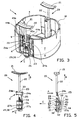
- the synthetic installation box 1 as depicted in figures 1 and 2 comprises a circumferential wall and an integrally formed bottom wall 3. At the side facing away from the bottom wall 3 the circumferential wall 2 changes into an upper edge 4, that defines an access opening to the interior of the installation box 1.
- the upper edge 4 is provided with a placement flange 10.
- a number of break-through gates 5 have been provided.
- the installation box 1 comprises two assembly holes 6 and insert slots 7, formed therebeneath, for otherwise not depicted nut plates into which locking bolts to be inserted through the assembly holes can be fixed.
- channels 9 have been formed integrally, which extend perpendicular to the bottom wall 3.
- these channels 3 have been provided with gear racks 11a, 11b.
- the teeth of the gear racks 11a, 11b have been provided with detaining planes 13 which extend parallel to the bottom wall 3 and face away from it.
- the channels 9 are open at their bottom end.
- a semicircular recess 12 has been formed in the placement flange 4.
- two longitudinal guides 45a, 45b have been formed which at the outer sides along an acute angle rim change into two longitudinal grooves 44a, 44b.
- two synthetic anchoring elements 20 have been placed in the channel 29, one of which has been depicted in figures 4-6 .
- the shown anchoring element 20 comprises a curved finger engagement 21, an elongated stem 22 that connects the finger engagement 21 via a break connection 33 with a guide 23, an intermediate portion 25 inclined to the stem 22, a first wedge member 26 that is rigidly connected with the intermediate portion 25, and the rear side 34 of which extends parallel to the stem 22, and a second wedge member 29 that is connected to the intermediate portion 25 by means of a bending strip 28.
- the guide 23 comprises two hook portions 24a, 24b that can partially snap behind the longitudinal guides 45a, 45b via the longitudinal grooves 44a, 44b.
- the first wedge member 26 comprises a right blocking tooth 27a and a left blocking tooth 27b which are resiliently connected to the first wedge member 26.
- the left tooth 27a and the right tooth 27b are staggered half a gear rack pitch with respect to each other.
- the first wedge member 26 comprises a first wedge plane 40, inclined to the rear side 34, facing the second wedge member 29, that at the lower end of the first wedge member 26 via a first abutment 41 that is directed transverse to the first wedge plane 40, changes into a second wedge plane 42.
- the second wedge member 29 comprises a third wedge plane 50 facing the first wedge member 26, that via a second abutment 51 changes into a fourth wedge plane 52.
- the first and third wedge plane 40, 50, and the second and fourth wedge plane 42, 52 are parallel to each other at a short distance from each other, wherein the distance between the first and second abutment 41, 52 is a multiple of the distance between said wedge planes.
- the second wedge member 29 comprises an anchoring plane 30 with a series of anchoring teeth 31 directed transverse thereto and projecting from the anchoring plane 30.
- An inclined run-off edge 32 extends between the lower anchoring position 31 and the anchoring plane 30.
- the anchoring positions 31 extend along the width of the anchoring plane.
- the anchoring positions can be divided in this orientation, wherein the teeth members are staggered with respect to each other in the longitudinal direction of the second wedge member 29.
- the anchoring positions 31 or the anchoring placement members may, alternatively, also be inclined to the anchoring plane 30, for instance with the free ends facing towards or away from each other, either in pairs or not.
- the second wedge member 29 comprises at the upper side at either side two transverse guides 53 which extend parallel to each other and transverse to the longitudinal direction, which as to shape and position are adapted to the teeth of the gear racks 11a, 11b so as to mesh therewith.
- the installation box 1 is particularly suited to be placed in a hole in a wall that has been constructed with plasterboards, wood, chipboard or combinations thereof.
- a blind hole is drilled with a diameter that is approximately equal to, or some millimeters larger than the diameter of the described circle D of the circumferential wall 2 of the installation box 1.
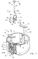
- an anchoring element 20 for securing the installation box 1 in the hole in the wall in each channel 9 an anchoring element 20, with the bending strip 28 in the unstretched condition, is placed partially in the channels 9 in direction A, wherein the guide 23 snaps behind the longitudinal guides 44a, 44b, the blocking teeth 27a, 27b at the first wedge member 26 engage the teeth of the gear racks 11a, 11b, the transverse guides 53 engage the higher positioned teeth of the gear racks 11a, 11b, the intermediate section 25 is incorporated between the teeth of the gear racks 11a, b, in a fitting manner and the stem 22 is partially incorporated in the recess 12.
- each first and second wedge member 26, 29 at the lower end extends above the plane of the bottom wall 3.
- the ends of the anchoring positions 30 are then still positioned within a described circle D of the installation wall 2.
- each anchoring element 20 is engaged between two fingers behind the finger engagements 21. Subsequently by pulling in the direction B the finger engagement 21 is moved away from the installation box 1, as a result of which the first wedge plane 26 moves upward in direction B with respect to the second wedge member 29 that is kept at a fixed height with respect to the bottom wall 3 by the transverse guides 53.
- the first and third wedge plane 40, 50 on the one hand, and the second and fourth wedge plane 42, 52 on the other hand become superposed by the mutual movement, after which during pulling out further in direction B the second wedge member 29 is partially moved out of the channel 9 by the cooperation of the wedge planes in direction C transverse to the wall 2.
- the second wedge member 29 moves in direction C within the radial circumferential area of the installation box 1, that is bounded by a plane that extends through the upper edge 4 and a plane that extends through the bottom wall 3.
- the anchoring positions 31 and subsequently the anchoring plane 30 arrive beyond the described circle D of the installation box 1 so as to fasten themselves against and partially in the circumferential wall of the hole.
- Direction C is directed parallel, in this example exactly parallel to the normal of the circumferential wall 3 and/or the plane of the bottom wall 3.
- direction C is at an angle of less than 10 degrees, preferably less than 5 degrees with respect to the normal of the circumferential wall 3 and/or the plane of the bottom wall 3.
- the pulling motion in direction B continues until the first abutment 41 and second abutment 52 become positioned against each other (as has been depicted in figure 6 also independently from the installation box 1) as a result of which the movement of the first wedge member 26 in direction B is blocked by the second wedge member 29.
- the break connection 33 breaks, as a result of which the upper side of the installation box 1 is exposed for applying switch material. Because of the operation of the blocking teeth 27a, 27b it is not possible to move the second wedge member 26 opposite to the direction B.
- an eyelet may be provided for insertion of a screw driver with which the finger engagement 21 can be turned, or the finger engagement 21 can be pulled.
Landscapes
- Engineering & Computer Science (AREA)
- Architecture (AREA)
- Civil Engineering (AREA)
- Structural Engineering (AREA)
- Connection Or Junction Boxes (AREA)
- Road Signs Or Road Markings (AREA)
- Forms Removed On Construction Sites Or Auxiliary Members Thereof (AREA)
- Joining Of Building Structures In Genera (AREA)
- Casings For Electric Apparatus (AREA)
Claims (19)
- Installationsdose (1), die in einem Loch einer Gebäudewand angeordnet werden soll, enthaltend eine Bodenwand (3), eine Umfangswand, bei der ein oberer Rand (4) eine Installationsöffnung begrenzt, und Verankerungseinrichtungen (20) zum Verankern der Installationsdose in dem Loch in der Wand, wobei die Verankerungseinrichtungen (20) ein Verankerungselement (29, 30) enthalten, das in eine Richtung (C) nach außen im Bezug auf die Umfangswand (2) im wesentlichen quer zur Umfangswand und/oder parallel zur Bodenwand (3) für einen Eingriff mit einer in Umfangsrichtung angrenzenden Wand des Loches bewegt werden kann, dadurch gekennzeichnet, dass die Verankerungseinrichtungen (20) ein Zugbetätigungselement (21, 22) enthalten, das im Bezug auf die Umfangswand (2) in einer Zugrichtung (B) weg von der Bodenwand (3) bewegt werden kann, um im Zusammenwirken mit dem Verankerungselement (29, 30) das Verankerungselement (29, 30) nach außen zu bewegen, wobei das Zugbetätigungselement (21, 22) während der Auswärtsbewegung des Verankerungselementes wenigstens teilweise über den oberen Rand (4) der Installationsdose (1) hinausragt.
- Installationsdose (1) nach Anspruch 1, bei der das Zugbetätigungselement (21, 22) im wesentlichen quer zur Bodenwand (3) und/oder parallel zur Umfangswand (2) bewegt werden kann.
- Installationsdose (1) nach einem der vorhergehenden Ansprüche, bei der das Verankerungselement (29, 30) in eine Auswärtsrichtung (C) im Bezug auf die Umfangswand (2) innerhalb eines radial äußeren Umfangsbereiches der Umfangswand (2) bewegt werden kann.
- Installationsdose (1) nach einem der vorhergehenden Ansprüche, bei der das Verankerungselement (29, 30) in eine Auswärtsrichtung (C) im Bezug auf die Umfangswand (2) bewegt werden kann, um im wesentlichen radial in die in Umfangsrichtung angrenzende Wand des Loches zu greifen.
- Installationsdose (1) nach einem der vorhergehenden Ansprüche, bei der das Verankerungselement (29, 30) und das Zugbetätigungselement (21, 22) im wesentlichen quer im Bezug zueinander bewegt werden können.
- Installationsdose (1) nach einem der vorhergehenden Ansprüche, bei der das Verankerungselement (29, 30) und das Zugbetätigungselement (21, 22) mit einer Wandlereinrichtung (26, 29) versehen sind, die eine Translation des Betätigungselementes (21, 22) in der Zugrichtung (B) in eine Translation des Verankerungselementes (29, 30) in die Auswärtsrichtung (C) umwandelt.
- Installationsdose (1) nach einem der vorhergehenden Ansprüche, bei der das Verankerungselement (29, 30) und/oder das Zugbetätigungselement (21, 22) eine Auflauffläche (52, 40) enthalten, die zur Zugrichtung (B) geneigt angeordnet ist, um die Zugbewegung des Betätigungselementes (21, 22) in die Auswärtsbewegung des Verankerungselementes (29, 30) umzuwandeln.
- Installationsdose (1) nach Anspruch 6 oder 7, bei der das Verankerungselement (29, 30) ein erstes Keilelement (29) und das Zugbetätigungselement (21, 22) ein zweites Keilelement (26) enthält, das mit dem ersten Keilelement (29) zusammenwirkt.
- Installationsdose nach Anspruch 8, bei der in einer Ausgangsstellung das erste und das zweite Keilelement (29, 26) gerade einander gegenüberliegend angeordnet sind.
- Installationsdose (1) nach einem der vorhergehenden Ansprüche, bei dem in Zugrichtung (B) das Verankerungselement (29, 30) und das Zugbetätigungselement (21, 22) in wechselseitig beweglicher Art miteinander verbunden sind.
- Installationsdose (1) nach Anspruch 9 oder 10, enthaltend ein bewegliches Gelenk (28) zwischen dem Verankerungselement (29, 30) und dem Zugbetätigungselement (21, 22).
- Installationsdose (1) nach einem der Ansprüche 6 bis 11, bei der das Verankerungselement (29, 30) und das Zugbetätigungselement (21, 22) zusammenwirkende Anschläge (51, 41) enthalten, die die Translation des Zugbetätigungselementes (21, 22) in einer äußerst ausgedehnten Stellung des Zugbetätigungselementes (21, 22) begrenzen.
- Installationsdose (1) nach einem der vorhergehenden Ansprüche, enthaltend erste Führungseinrichtungen (11a, b, 53), die das Verankerungselement (29, 30) in seiner Auswärtsrichtung (C) führen und einer Bewegung des Verankerungselementes (29, 30) in der Zugrichtung (B) entgegenwirken, wobei die ersten Führungseinrichtungen (11a, b, 53) vorzugsweise erste Zähne (11a, b) auf gegenüberliegenden Seiten eines Kanals (9), der in der Umfangswand (2) ausgebildet ist, und zweite Zähne (53) am Verankerungselement (29, 30) enthalten, wobei die zweiten Zähne (53) mit den ersten Zähnen (11a, b) zusammenwirken und die ersten Zähne (11a, b) in die zweiten Zähne (53) greifen und sich quer zur Umfangswand (2) erstrecken.
- Installationsdose (1) nach einem der vorhergehenden Ansprüche, enthaltend zweite Führungseinrichtungen (44a, b, 24a, b), die das Zugbetätigungselement (21, 22) im Bezug auf die Umfangswand (2) führen, wobei die zweiten Führungseinrichtungen (44a, b, 24a, b) vorzugsweise einen Kanal (9) enthalten, der in der Umfangswand (2) ausgebildet ist, um wenigstens einen Abschnitt des Zugbetätigungselementes (21, 22) aufzunehmen, und die zweiten Führungseinrichtungen (44a, b, 24a, b) vorzugsweise eine längliche Führung oder Schiene (44a, b), die sich entlang des Kanals (9) erstreckt, sowie einen Eingriffsteil (24a, b) enthalten, der mit dem Zugbetätigungselement (21, 22) verbunden ist, wobei dieser Eingriffsteil (24a, b) in die längliche Führung (44a, b) greift.
- Installationsdose (1) nach einem der vorhergehenden Ansprüche, enthaltend Blockiereinrichtungen (11 a, b, 27a, b), die einer Rückwärtsbewegung des Zugbetätigungselementes (21, 22) entgegenwirken, wobei die Blockiereinrichtungen (11a, b, 27a, b) vorzugsweise dritte Zähne (11a, b) auf gegenüberliegenden Seiten eines Kanals (9), der in der Umfangswand (2) ausgebildet ist, und vierte Zähne (27a, b) auf gegenüberliegenden Seiten des Zugbetätigungselementes (21, 22) enthalten, wobei die vierten Zähne (27a, b) mit den dritten Zähnen (11a, b) zusammenwirken und in Zugrichtung (B) die dritten und/oder vierten Zähne (11a, b, 27a, b) auf gegenüberliegenden Seiten des Zugbetätigungselementes (21, 22) im Bezug zueinander vorzugsweise um einen halben Zahn versetzt sind.
- Installationsdose (1) nach einem der Ansprüche 13 bis 15, bei der der Kanal (9) quer zur Bodenwand (3) der Installationsdose (1) ausgerichtet ist.
- Installationsdose (1) nach einem der vorhergehenden Ansprüche, bei der das Zugbetätigungselement (21, 22) einen Fingereingriffsteil (21) enthält, um das Zugbetätigungselement (21, 22) manuell von der Bodenwand (3) wegzuziehen, wobei der Fingereingriffsteil (21) mit Hilfe einer vorbestimmten Bruchverbindung (33) vorzugsweise einer vorbestimmten Torsionsbruchverbindung vorzugsweise eine Einheit mit dem Zugbetätigungselement (21, 22) bildet.
- Installationsdose (1) nach einem der vorhergehenden Ansprüche, bei der das Verankerungselement (29, 30) eine Eingriffsoberfläche (30) enthält, die einen fünften Zahn oder Zähne (31) hat, der/die in die angrenzende Wand des Loches greift/greifen.
- Installationsdose (1), die in einem Loch in einer Wand eines Gebäudes angeordnet werden soll, enthaltend eine Bodenwand (3)), eine Umfangswand (2), die eine Installationsöffnung begrenzt, und Verankerungseinrichtungen (20) zum Verankern der Installationsdose (1) in dem Loch in der Wand, wobei die Verankerungseinrichtungen (20) enthalten: ein Verankerungselement (29, 30), das mit der Wand in Eingriff gelangt, ein Zugbetätigungselement (21, 22), das in einer Zugrichtung (B) von der Bodenwand (3) durch einen Kanal (9) weggezogen werden kann, der in der Umfangswand (2) ausgebildet ist, und Blockiereinrichtungen (111a, b, 27a, b), die eine Rückwärtsbewegung des Zügbetäügungseiemenies (21, 22) entgegenwirken, wobei die Blockiereinrichtungen (11a, b, 27a, b) dritte Zähne (11a, b) auf gegenüberliegenden Seiten des Kanals (9) und vierte Zähne (27a, b) auf gegenüberliegenden Seiten des Zugbetätigungselementes (21, 22) enthalten, wobei die dritten Zähne (11a, b) mit den vierten Zähnen (27a, b) zusammenwirken, dadurch gekennzeichnet, dass in Zugrichtung (B) die dritten und/oder vierten Zähne (11a, b, 27a, b) auf gegenüberliegenden Seiten des Zugbetätigungselementes (21, 22) im Bezug zueinander um einen halben Zahn versetzt sind.
Applications Claiming Priority (1)
| Application Number | Priority Date | Filing Date | Title |
|---|---|---|---|
| NL1033126A NL1033126C2 (nl) | 2006-12-22 | 2006-12-22 | Installatiedoos met verankeringsmiddelen. |
Publications (2)
| Publication Number | Publication Date |
|---|---|
| EP1944846A1 EP1944846A1 (de) | 2008-07-16 |
| EP1944846B1 true EP1944846B1 (de) | 2010-02-24 |
Family
ID=38137494
Family Applications (1)
| Application Number | Title | Priority Date | Filing Date |
|---|---|---|---|
| EP07076091A Not-in-force EP1944846B1 (de) | 2006-12-22 | 2007-12-14 | Installationsdose mit Verankerungsmitteln |
Country Status (6)
| Country | Link |
|---|---|
| EP (1) | EP1944846B1 (de) |
| AT (1) | ATE459119T1 (de) |
| DE (1) | DE602007004937D1 (de) |
| DK (1) | DK1944846T3 (de) |
| ES (1) | ES2340809T3 (de) |
| NL (1) | NL1033126C2 (de) |
Cited By (1)
| Publication number | Priority date | Publication date | Assignee | Title |
|---|---|---|---|---|
| US11557888B2 (en) | 2019-02-14 | 2023-01-17 | Erico International Corporation | Adjustable depth electrical wall mount ring |
Families Citing this family (3)
| Publication number | Priority date | Publication date | Assignee | Title |
|---|---|---|---|---|
| US9088143B2 (en) | 2013-02-10 | 2015-07-21 | Gerald Macaulay Brey | Apparatus and method for mounting an electrical junction box |
| FR3013914B1 (fr) * | 2013-11-22 | 2015-12-11 | Legrand France | Support d'appareillage comportant un accessoire de griffage pour sa fixation a une boite murale, accessoire de griffage, ensemble de griffage et appareillage electrique associes |
| DK3355427T3 (da) * | 2017-01-31 | 2021-05-03 | Abb Schweiz Ag | Installationsboks med forankringsstrimmel til en hul væg |
Family Cites Families (4)
| Publication number | Priority date | Publication date | Assignee | Title |
|---|---|---|---|---|
| DE2213277C3 (de) * | 1972-03-18 | 1982-03-11 | Lange & Co, 5880 Lüdenscheid | Elektrische Abzweigdose |
| DE3041919A1 (de) * | 1980-11-06 | 1982-06-03 | Günther Spelsberg GmbH & Co KG, 5885 Schalksmühle | Hohlwanddose, wie einbaudose, wandausladose u.dgl., zur aufnahme elektrischer installationsgegenstaende |
| DK199901015A (da) * | 1999-07-13 | 2001-05-02 | Lk As | Fremgangsmåde til etablering af en monteringsramme for elektriske komponenter, koblingsramme til udøvelse af fremgangsmåden, samt et skjult elektrisk installationssystem til samvirkning med koblingsrammen |
| NL1020862C2 (nl) * | 2002-01-23 | 2005-12-30 | Abb Bv | Holle-wanddoos. |
-
2006
- 2006-12-22 NL NL1033126A patent/NL1033126C2/nl not_active IP Right Cessation
-
2007
- 2007-12-14 EP EP07076091A patent/EP1944846B1/de not_active Not-in-force
- 2007-12-14 DE DE602007004937T patent/DE602007004937D1/de active Active
- 2007-12-14 DK DK07076091.3T patent/DK1944846T3/da active
- 2007-12-14 AT AT07076091T patent/ATE459119T1/de not_active IP Right Cessation
- 2007-12-14 ES ES07076091T patent/ES2340809T3/es active Active
Cited By (1)
| Publication number | Priority date | Publication date | Assignee | Title |
|---|---|---|---|---|
| US11557888B2 (en) | 2019-02-14 | 2023-01-17 | Erico International Corporation | Adjustable depth electrical wall mount ring |
Also Published As
| Publication number | Publication date |
|---|---|
| ATE459119T1 (de) | 2010-03-15 |
| ES2340809T3 (es) | 2010-06-09 |
| EP1944846A1 (de) | 2008-07-16 |
| DE602007004937D1 (de) | 2010-04-08 |
| NL1033126C2 (nl) | 2008-06-30 |
| DK1944846T3 (da) | 2010-06-07 |
Similar Documents
| Publication | Publication Date | Title |
|---|---|---|
| EP1944846B1 (de) | Installationsdose mit Verankerungsmitteln | |
| RU2433238C2 (ru) | Дверная и оконная рама | |
| US8376021B2 (en) | Component for producing a sectional door panel, shell for such a component, reinforcement strut for such a component, sectional door panel having such a component, and sectional door having a corresponding sectional door panel | |
| US20050022941A1 (en) | Transmission rod for accessories for windows and doors | |
| GB2456181A (en) | Window installation and method | |
| RU2640814C2 (ru) | Отделочная пластина, оснащенная средствами центрирования на внутреннем элементе электрического устройства | |
| EP0767521B1 (de) | Multifunktionskanal | |
| US20180026577A1 (en) | Device for attaching a solar panel | |
| EP2700781B1 (de) | Fensterauskleidungsanordnung mit verbessertem Eckbeschlag | |
| EP2700780B1 (de) | Fensterauskleidungsanordnung mit verbessertem Montagebeschlag | |
| EP3768933B1 (de) | Montage eines kastens, insbesondere eines rollladenkastens, und einbaurahmen | |
| EP3319825B1 (de) | Fenster- oder türabdeckungsanordnung für ein fahrzeug | |
| JP4173856B2 (ja) | パネル連結固定装置 | |
| EP3039215B1 (de) | Befestigungsklammer und verfahren zur befestigung eines fertigungsrahmens an einem rahmen eines fensters oder dergleichen sowie mit solch einer befestigungsklammer ausgerüstetes fenster | |
| DE102013003823A1 (de) | Sanitärarmatur mit einer Rosette | |
| KR200409062Y1 (ko) | 케이블 고정용 정렬클립 | |
| KR100477031B1 (ko) | 도어 인사이드 핸들의 결합구조 | |
| EP2716854B1 (de) | Rollladen und Panzeranbindungsmodul dafür | |
| RU197832U1 (ru) | Профиль направляющей для жалюзи | |
| KR102421686B1 (ko) | 탈거방지를 위한 조립식 결로방지패드 및 이를 포함하는 창호브라켓 | |
| EP1561889B1 (de) | Konstruktion für ein Fenster, eine Tür oder ähnliches | |
| JP4333408B2 (ja) | 戸 | |
| UA92566C2 (uk) | Привідний механізм щонайменше з однією привідною штангою і щонайменше з одним напрямним елементом привідної штанги | |
| KR102025185B1 (ko) | 연동 도어 장착용 도어 수직 프레임 | |
| EP3635193B1 (de) | Wandverkleidung |
Legal Events
| Date | Code | Title | Description |
|---|---|---|---|
| PUAI | Public reference made under article 153(3) epc to a published international application that has entered the european phase |
Free format text: ORIGINAL CODE: 0009012 |
|
| AK | Designated contracting states |
Kind code of ref document: A1 Designated state(s): AT BE BG CH CY CZ DE DK EE ES FI FR GB GR HU IE IS IT LI LT LU LV MC MT NL PL PT RO SE SI SK TR |
|
| AX | Request for extension of the european patent |
Extension state: AL BA HR MK RS |
|
| 17P | Request for examination filed |
Effective date: 20080828 |
|
| 17Q | First examination report despatched |
Effective date: 20081118 |
|
| AKX | Designation fees paid |
Designated state(s): AT BE BG CH CY CZ DE DK EE ES FI FR GB GR HU IE IS IT LI LT LU LV MC MT NL PL PT RO SE SI SK TR |
|
| GRAP | Despatch of communication of intention to grant a patent |
Free format text: ORIGINAL CODE: EPIDOSNIGR1 |
|
| GRAS | Grant fee paid |
Free format text: ORIGINAL CODE: EPIDOSNIGR3 |
|
| GRAA | (expected) grant |
Free format text: ORIGINAL CODE: 0009210 |
|
| AK | Designated contracting states |
Kind code of ref document: B1 Designated state(s): AT BE BG CH CY CZ DE DK EE ES FI FR GB GR HU IE IS IT LI LT LU LV MC MT NL PL PT RO SE SI SK TR |
|
| REG | Reference to a national code |
Ref country code: GB Ref legal event code: FG4D |
|
| REG | Reference to a national code |
Ref country code: CH Ref legal event code: EP |
|
| REG | Reference to a national code |
Ref country code: IE Ref legal event code: FG4D |
|
| REF | Corresponds to: |
Ref document number: 602007004937 Country of ref document: DE Date of ref document: 20100408 Kind code of ref document: P |
|
| REG | Reference to a national code |
Ref country code: NL Ref legal event code: T3 |
|
| REG | Reference to a national code |
Ref country code: SE Ref legal event code: TRGR |
|
| REG | Reference to a national code |
Ref country code: DK Ref legal event code: T3 |
|
| REG | Reference to a national code |
Ref country code: ES Ref legal event code: FG2A Ref document number: 2340809 Country of ref document: ES Kind code of ref document: T3 |
|
| LTIE | Lt: invalidation of european patent or patent extension |
Effective date: 20100224 |
|
| PG25 | Lapsed in a contracting state [announced via postgrant information from national office to epo] |
Ref country code: LT Free format text: LAPSE BECAUSE OF FAILURE TO SUBMIT A TRANSLATION OF THE DESCRIPTION OR TO PAY THE FEE WITHIN THE PRESCRIBED TIME-LIMIT Effective date: 20100224 Ref country code: PT Free format text: LAPSE BECAUSE OF FAILURE TO SUBMIT A TRANSLATION OF THE DESCRIPTION OR TO PAY THE FEE WITHIN THE PRESCRIBED TIME-LIMIT Effective date: 20100625 Ref country code: IS Free format text: LAPSE BECAUSE OF FAILURE TO SUBMIT A TRANSLATION OF THE DESCRIPTION OR TO PAY THE FEE WITHIN THE PRESCRIBED TIME-LIMIT Effective date: 20100624 |
|
| PG25 | Lapsed in a contracting state [announced via postgrant information from national office to epo] |
Ref country code: LV Free format text: LAPSE BECAUSE OF FAILURE TO SUBMIT A TRANSLATION OF THE DESCRIPTION OR TO PAY THE FEE WITHIN THE PRESCRIBED TIME-LIMIT Effective date: 20100224 Ref country code: PL Free format text: LAPSE BECAUSE OF FAILURE TO SUBMIT A TRANSLATION OF THE DESCRIPTION OR TO PAY THE FEE WITHIN THE PRESCRIBED TIME-LIMIT Effective date: 20100224 Ref country code: SI Free format text: LAPSE BECAUSE OF FAILURE TO SUBMIT A TRANSLATION OF THE DESCRIPTION OR TO PAY THE FEE WITHIN THE PRESCRIBED TIME-LIMIT Effective date: 20100224 Ref country code: AT Free format text: LAPSE BECAUSE OF FAILURE TO SUBMIT A TRANSLATION OF THE DESCRIPTION OR TO PAY THE FEE WITHIN THE PRESCRIBED TIME-LIMIT Effective date: 20100224 Ref country code: FI Free format text: LAPSE BECAUSE OF FAILURE TO SUBMIT A TRANSLATION OF THE DESCRIPTION OR TO PAY THE FEE WITHIN THE PRESCRIBED TIME-LIMIT Effective date: 20100224 |
|
| PG25 | Lapsed in a contracting state [announced via postgrant information from national office to epo] |
Ref country code: RO Free format text: LAPSE BECAUSE OF FAILURE TO SUBMIT A TRANSLATION OF THE DESCRIPTION OR TO PAY THE FEE WITHIN THE PRESCRIBED TIME-LIMIT Effective date: 20100224 Ref country code: GR Free format text: LAPSE BECAUSE OF FAILURE TO SUBMIT A TRANSLATION OF THE DESCRIPTION OR TO PAY THE FEE WITHIN THE PRESCRIBED TIME-LIMIT Effective date: 20100525 Ref country code: EE Free format text: LAPSE BECAUSE OF FAILURE TO SUBMIT A TRANSLATION OF THE DESCRIPTION OR TO PAY THE FEE WITHIN THE PRESCRIBED TIME-LIMIT Effective date: 20100224 Ref country code: CY Free format text: LAPSE BECAUSE OF FAILURE TO SUBMIT A TRANSLATION OF THE DESCRIPTION OR TO PAY THE FEE WITHIN THE PRESCRIBED TIME-LIMIT Effective date: 20100224 |
|
| PG25 | Lapsed in a contracting state [announced via postgrant information from national office to epo] |
Ref country code: BG Free format text: LAPSE BECAUSE OF FAILURE TO SUBMIT A TRANSLATION OF THE DESCRIPTION OR TO PAY THE FEE WITHIN THE PRESCRIBED TIME-LIMIT Effective date: 20100524 Ref country code: CZ Free format text: LAPSE BECAUSE OF FAILURE TO SUBMIT A TRANSLATION OF THE DESCRIPTION OR TO PAY THE FEE WITHIN THE PRESCRIBED TIME-LIMIT Effective date: 20100224 Ref country code: SK Free format text: LAPSE BECAUSE OF FAILURE TO SUBMIT A TRANSLATION OF THE DESCRIPTION OR TO PAY THE FEE WITHIN THE PRESCRIBED TIME-LIMIT Effective date: 20100224 |
|
| PLBE | No opposition filed within time limit |
Free format text: ORIGINAL CODE: 0009261 |
|
| STAA | Information on the status of an ep patent application or granted ep patent |
Free format text: STATUS: NO OPPOSITION FILED WITHIN TIME LIMIT |
|
| 26N | No opposition filed |
Effective date: 20101125 |
|
| PG25 | Lapsed in a contracting state [announced via postgrant information from national office to epo] |
Ref country code: IT Free format text: LAPSE BECAUSE OF FAILURE TO SUBMIT A TRANSLATION OF THE DESCRIPTION OR TO PAY THE FEE WITHIN THE PRESCRIBED TIME-LIMIT Effective date: 20100224 |
|
| PG25 | Lapsed in a contracting state [announced via postgrant information from national office to epo] |
Ref country code: MC Free format text: LAPSE BECAUSE OF NON-PAYMENT OF DUE FEES Effective date: 20101231 |
|
| PG25 | Lapsed in a contracting state [announced via postgrant information from national office to epo] |
Ref country code: MT Free format text: LAPSE BECAUSE OF FAILURE TO SUBMIT A TRANSLATION OF THE DESCRIPTION OR TO PAY THE FEE WITHIN THE PRESCRIBED TIME-LIMIT Effective date: 20100224 |
|
| REG | Reference to a national code |
Ref country code: CH Ref legal event code: PL |
|
| PG25 | Lapsed in a contracting state [announced via postgrant information from national office to epo] |
Ref country code: LU Free format text: LAPSE BECAUSE OF NON-PAYMENT OF DUE FEES Effective date: 20101214 Ref country code: HU Free format text: LAPSE BECAUSE OF FAILURE TO SUBMIT A TRANSLATION OF THE DESCRIPTION OR TO PAY THE FEE WITHIN THE PRESCRIBED TIME-LIMIT Effective date: 20100825 |
|
| PG25 | Lapsed in a contracting state [announced via postgrant information from national office to epo] |
Ref country code: CH Free format text: LAPSE BECAUSE OF NON-PAYMENT OF DUE FEES Effective date: 20111231 Ref country code: TR Free format text: LAPSE BECAUSE OF FAILURE TO SUBMIT A TRANSLATION OF THE DESCRIPTION OR TO PAY THE FEE WITHIN THE PRESCRIBED TIME-LIMIT Effective date: 20100224 Ref country code: LI Free format text: LAPSE BECAUSE OF NON-PAYMENT OF DUE FEES Effective date: 20111231 |
|
| PGFP | Annual fee paid to national office [announced via postgrant information from national office to epo] |
Ref country code: DK Payment date: 20141212 Year of fee payment: 8 |
|
| PGFP | Annual fee paid to national office [announced via postgrant information from national office to epo] |
Ref country code: SE Payment date: 20141203 Year of fee payment: 8 Ref country code: ES Payment date: 20141114 Year of fee payment: 8 Ref country code: GB Payment date: 20141202 Year of fee payment: 8 Ref country code: IE Payment date: 20141203 Year of fee payment: 8 |
|
| PGFP | Annual fee paid to national office [announced via postgrant information from national office to epo] |
Ref country code: BE Payment date: 20141202 Year of fee payment: 8 |
|
| REG | Reference to a national code |
Ref country code: FR Ref legal event code: PLFP Year of fee payment: 9 |
|
| PG25 | Lapsed in a contracting state [announced via postgrant information from national office to epo] |
Ref country code: BE Free format text: LAPSE BECAUSE OF NON-PAYMENT OF DUE FEES Effective date: 20151231 |
|
| REG | Reference to a national code |
Ref country code: DK Ref legal event code: EBP Effective date: 20151231 |
|
| REG | Reference to a national code |
Ref country code: SE Ref legal event code: EUG |
|
| GBPC | Gb: european patent ceased through non-payment of renewal fee |
Effective date: 20151214 |
|
| PG25 | Lapsed in a contracting state [announced via postgrant information from national office to epo] |
Ref country code: SE Free format text: LAPSE BECAUSE OF NON-PAYMENT OF DUE FEES Effective date: 20151215 |
|
| REG | Reference to a national code |
Ref country code: IE Ref legal event code: MM4A |
|
| PG25 | Lapsed in a contracting state [announced via postgrant information from national office to epo] |
Ref country code: IE Free format text: LAPSE BECAUSE OF NON-PAYMENT OF DUE FEES Effective date: 20151214 Ref country code: GB Free format text: LAPSE BECAUSE OF NON-PAYMENT OF DUE FEES Effective date: 20151214 |
|
| REG | Reference to a national code |
Ref country code: FR Ref legal event code: PLFP Year of fee payment: 10 |
|
| REG | Reference to a national code |
Ref country code: ES Ref legal event code: FD2A Effective date: 20170126 |
|
| PG25 | Lapsed in a contracting state [announced via postgrant information from national office to epo] |
Ref country code: DK Free format text: LAPSE BECAUSE OF NON-PAYMENT OF DUE FEES Effective date: 20151231 |
|
| PGFP | Annual fee paid to national office [announced via postgrant information from national office to epo] |
Ref country code: DE Payment date: 20161213 Year of fee payment: 10 Ref country code: NL Payment date: 20161221 Year of fee payment: 10 |
|
| PG25 | Lapsed in a contracting state [announced via postgrant information from national office to epo] |
Ref country code: ES Free format text: LAPSE BECAUSE OF NON-PAYMENT OF DUE FEES Effective date: 20151215 |
|
| PGFP | Annual fee paid to national office [announced via postgrant information from national office to epo] |
Ref country code: FR Payment date: 20161222 Year of fee payment: 10 |
|
| REG | Reference to a national code |
Ref country code: DE Ref legal event code: R119 Ref document number: 602007004937 Country of ref document: DE |
|
| REG | Reference to a national code |
Ref country code: NL Ref legal event code: MM Effective date: 20180101 |
|
| PG25 | Lapsed in a contracting state [announced via postgrant information from national office to epo] |
Ref country code: NL Free format text: LAPSE BECAUSE OF NON-PAYMENT OF DUE FEES Effective date: 20180101 |
|
| REG | Reference to a national code |
Ref country code: FR Ref legal event code: ST Effective date: 20180831 |
|
| PG25 | Lapsed in a contracting state [announced via postgrant information from national office to epo] |
Ref country code: DE Free format text: LAPSE BECAUSE OF NON-PAYMENT OF DUE FEES Effective date: 20180703 Ref country code: FR Free format text: LAPSE BECAUSE OF NON-PAYMENT OF DUE FEES Effective date: 20180102 |