EP1944206A1 - Vehicle seatbelt - Google Patents
Vehicle seatbelt Download PDFInfo
- Publication number
- EP1944206A1 EP1944206A1 EP06811664A EP06811664A EP1944206A1 EP 1944206 A1 EP1944206 A1 EP 1944206A1 EP 06811664 A EP06811664 A EP 06811664A EP 06811664 A EP06811664 A EP 06811664A EP 1944206 A1 EP1944206 A1 EP 1944206A1
- Authority
- EP
- European Patent Office
- Prior art keywords
- webbing
- buckle
- band
- guide member
- loop portion
- Prior art date
- Legal status (The legal status is an assumption and is not a legal conclusion. Google has not performed a legal analysis and makes no representation as to the accuracy of the status listed.)
- Granted
Links
Images



Classifications
-
- B—PERFORMING OPERATIONS; TRANSPORTING
- B60—VEHICLES IN GENERAL
- B60R—VEHICLES, VEHICLE FITTINGS, OR VEHICLE PARTS, NOT OTHERWISE PROVIDED FOR
- B60R22/00—Safety belts or body harnesses in vehicles
- B60R22/18—Anchoring devices
- B60R22/26—Anchoring devices secured to the seat
-
- B—PERFORMING OPERATIONS; TRANSPORTING
- B60—VEHICLES IN GENERAL
- B60R—VEHICLES, VEHICLE FITTINGS, OR VEHICLE PARTS, NOT OTHERWISE PROVIDED FOR
- B60R22/00—Safety belts or body harnesses in vehicles
- B60R22/02—Semi-passive restraint systems, e.g. systems applied or removed automatically but not both ; Manual restraint systems
- B60R2022/021—Means for holding the tongue or buckle in a non-use position, e.g. for easy access by the user
-
- B—PERFORMING OPERATIONS; TRANSPORTING
- B60—VEHICLES IN GENERAL
- B60R—VEHICLES, VEHICLE FITTINGS, OR VEHICLE PARTS, NOT OTHERWISE PROVIDED FOR
- B60R22/00—Safety belts or body harnesses in vehicles
- B60R22/18—Anchoring devices
- B60R2022/1806—Anchoring devices for buckles
Definitions
- the present invention relates to a vehicle seatbelt mounted on an automobile, etc,.
- Patent Document 1 Japanese Unexamined Patent Application Publication No. 2005-119433 ( Fig. 1 )
- the band may become misaligned/lengthened.
- the circular rubber band is displaced below the buckle, so that the power of the circular rubber band holding the buckle belt is reduced, resulting in the drooping down of the buckle from the seat.
- the vehicle seatbelt in a vehicle seatbelt including a buckle webbing arranged on the side of a seat and a buckle mounted at an end of the buckle webbing to be detachably attached to a tongue provided in a tongue webbing, the vehicle seatbelt includes an elastic holding band connected to the seat for holding the buckle webbing inside the seat by stretching the buckle webbing and position fixing means for fixing the position of the elastic holding band relative to the buckle webbing.
- the elastic holding band when the buckle webbing is stretched inside the seat by the elastic holding band, the elastic holding band is connected to a predetermined position of the seat so that the buckle is held in an erected state from the seat, for example. At this time, since the position of the elastic holding band relative to the buckle webbing is fixed by the position fixing means, the elastic holding band is suppressed from being displaced downward (oppositely to the buckle). Thereby, even when the elastic holding band is used for a long time, the reduction in the power holding the buckle webbing by the elastic holding band can be suppressed.
- the buckle webbing is provided with a webbing loop portion formed at an end in a loop shape and connected to the buckle
- the position fixing means includes a band guide member mounted to the webbing loop portion so that the band guide member passes inside and outside the loop of the webbing loop portion, and the elastic holding band passes through the band guide member as well as the elastic holding band is routed to wrap the webbing loop portion therewith from the outside of the loop of the webbing loop portion operatively in associated with the band guide member.
- the width of the band guide member is smaller than that of the portion of the buckle webbing other than the webbing loop portion.
- the band guide member in a state of the buckle erected from the seat, for example, even the band guide member is to be displaced downward along the buckle webbing, the band guide member is caught at a position where the buckle webbing increases in width larger than the band guide member. Therefore, the band guide member can be restricted at a position above the root of the webbing loop portion.
- the reduction in the power holding the buckle belt can be suppressed, so that the drooping down of the buckle from the seat can be suppressed.
- the buckle 5 is difficult to interfere with the adjacent seat.
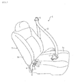
- Fig. 1 is a perspective view showing an embodiment of the vehicle seatbelt according to the present invention along with a seat.
- the vehicle seatbelt according to the embodiment may be incorporated in an automobile rear seat.
- the vehicle seatbelt 1 includes a tongue webbing 2, a tongue 3 provided in the intermediate portion of the tongue webbing 2, a buckle webbing 4, and a buckle 5 mounted at an end of the buckle webbing 4 to be detachably attached to the tongue 3.
- the tongue webbing 2 is withdrawn from a retractor (not shown) retractably toward an upper part of a vehicle body, and is further inserted into a through ring 6 so as to turn back toward a lower part of the vehicle body.
- One end of the tongue webbing 2 is fixed to an anchor plate (not shown) provided on one side of a seat 7.
- the tongue 3 is provided so that the tongue webbing 2 is inserted to the tongue 3 in the intermediate portion of the tongue webbing 2.
- the buckle webbing 4 is fixed to an anchor plate 8 provided on the other side of the seat 7.
- a loop-shaped webbing loop portion 9 is provided at one end of the buckle webbing 4.
- the webbing loop portion 9 is connected to the buckle 5 in a state hooked on a frame 5a of the buckle 5.
- a pattern stitched portion 10 is provided in the vicinity of the webbing loop portion 9 of the buckle webbing 4, by stitching overlapping portions together, which are made by folding back the buckle webbing 4 in a loop shape.
- the width of the webbing loop portion 9 is smaller than the width W 1 of the portion of the buckle webbing 4 other than the webbing loop portion 9. Moreover, the width of the webbing loop portion 9 is tapered toward its end (the buckle 5).
- a storage recess 11 is formed for accommodating the buckle 5 therein.
- a rubber elastic holding band 12 is provided for stretching the buckle webbing 4 inside the seat cushion 7a to hold it therein.
- the elastic holding band 12 may be a string type or a band shape.
- the webbing loop portion 9 of the buckle webbing 4 is provided with a band guide member 13 mounted to be inserted by the elastic holding band 12 thereinto.
- the band guide member 13 is made from cloth or a resin.
- the band guide member 13 is formed by being sewn to wrap a branch of the webbing loop portion 9 adjacent to the seat 7 therewith so as to pass inside and outside of the loop.
- the width W 2 of the band guide member 13 is smaller than the width W 1 of the portion of the buckle webbing 4 other than the webbing loop portion 9.
- the elastic holding band 12 is inserted into the band guide member 13 as well as is routed to wrap the webbing loop portion 9 therewith from the outside of the loop of the webbing loop portion 9 operatively in associated with the band guide member 13.
- one end of the elastic holding band 12 is connected at a band fixing position provided in the storage recess 11 of the seat 7.
- the elastic holding band 12 is inserted into the band guide member 13 from the below (the rear anchor of the buckle webbing 4).
- the elastic holding band 12 is wrapped around the webbing loop portion 9 so that the elastic holding band 12 does not pass inside the loop of the webbing loop portion 9 but passes outside the loop of the webbing loop portion 9.
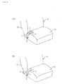
- the buckle 5 when the elastic holding band 12 and the band guide member 13 are not provided like in the past, as shown in Fig. 4(a) , the buckle 5 is generally accommodated in the storage recess 11 of the seat 7; however, the buckle 5, as shown in Fig. 4(b) , may hang down or drop out of the seat 7 due to factors such as vibration.
- a strap or a rubber band may be attached on the side of the seat 7; however, if the strap becomes misaligned/lengthened so as to be displaced downward during service, for example, the buckle 5 may hang down in the same way. In such a state, when the seat 7 is slid in the front-back direction, for example, the buckle 5 may interfere with the adjacent seat.
- the band guide member 13 is mounted on the webbing loop portion 9 of the buckle webbing 4; the elastic holding band 12 connected to the seat 7 is configured to pass through the band guide member 13 and to wrap the webbing loop portion 9 therewith, so that the webbing loop portion 9 is stretched and held inside the seat 7 by the elastic holding band 12.
- the buckle webbing 4 is held in an erected state from the seat cushion 7a; alternatively, as shown in Fig. 5(b) , the buckle webbing 4 is held so that the buckle 5 is accommodated within the storage recess 11 of the seat 7.
- the elastic holding band 12 may become lengthened during service, for example, it may be displaced below (oppositely to the buckle 5).
- the width W 2 of the band guide member 13 is smaller than the width W 1 of the buckle webbing 4, so that even the band guide member 13 is to be displaced downward along the webbing loop portion 9, the band guide member 13 is caught on the root of the webbing loop portion 9 (see Fig. 3 ). That is, the downward movement of the band guide member 13 is restricted by the root of the webbing loop portion 9, so that the position of the band guide member 13 relative to the webbing loop portion 9 is fixed.
- the elastic holding band 12 passing through the band guide member 13 is also suppressed from being displaced downward, so that the position stretching the webbing loop portion 9 by the elastic holding band 12 is fixed.
- the reduction in the power holding the buckle webbing 4 by the elastic holding band 12 is suppressed, so that the drooping down or the dropping out of the buckle 5 can be suppressed. Consequently, it can be suppressed that when the seat 7 is slid in the front-back direction, for example, the buckle 5 interferes with the adjacent seat.
- the band guide member 13 Since the band guide member 13 is mounted on the webbing loop portion 9; the elastic holding band 12 passing through the band guide member 13 is configured to outside wrap the loop of the webbing loop portion 9, when the webbing loop portion 9 is stretched and held inside the seat 7 by the elastic holding band 12, a force can be effectively exerted for putting the buckle 5 down onto the seat 7.
- the holding structure of the buckle webbing 4 is not of a large scale, but can be achieved in low cost.
- the width W 1 of the buckle webbing 4 may be wholly the same, including the webbing loop portion 9.
- another webbing is overlapped on the root of the webbing loop portion 9 and sewn together so as to increase the thickness of that portion.
- the vehicle seatbelt 1 according to the embodiment is applied to the rear seat; however, the vehicle seatbelt according to the present invention may be obviously incorporated in a front seat, if possible.
Landscapes
- Engineering & Computer Science (AREA)
- Mechanical Engineering (AREA)
- Automotive Seat Belt Assembly (AREA)
- Emergency Lowering Means (AREA)
Abstract
Description
- The present invention relates to a vehicle seatbelt mounted on an automobile, etc,.
- A conventional vehicle seatbelt has been known in that a circular rubber band is attached on an epidermal surface of a seat and a buckle-webbing withdrawn from the lateral of the seat is inserted into the circular rubber band, so that the drooping down of the buckle is prevented by stretching the buckle-webbing toward the seat surface with the circular rubber band (see Patent Document 1). Patent Document 1: Japanese Unexamined Patent Application Publication No.
2005-119433 Fig. 1 ) - However, in the conventional technique mentioned above, during use of the circular rubber band, the band may become misaligned/lengthened. In this case, the circular rubber band is displaced below the buckle, so that the power of the circular rubber band holding the buckle belt is reduced, resulting in the drooping down of the buckle from the seat.
- It is an object of the present invention to provide a vehicle seatbelt capable of suppressing the reduction in the power holding a buckle webbing.
- In order to achieve the above object, according to a first invention, in a vehicle seatbelt including a buckle webbing arranged on the side of a seat and a buckle mounted at an end of the buckle webbing to be detachably attached to a tongue provided in a tongue webbing, the vehicle seatbelt includes an elastic holding band connected to the seat for holding the buckle webbing inside the seat by stretching the buckle webbing and position fixing means for fixing the position of the elastic holding band relative to the buckle webbing.
- In such a vehicle seatbelt, when the buckle webbing is stretched inside the seat by the elastic holding band, the elastic holding band is connected to a predetermined position of the seat so that the buckle is held in an erected state from the seat, for example. At this time, since the position of the elastic holding band relative to the buckle webbing is fixed by the position fixing means, the elastic holding band is suppressed from being displaced downward (oppositely to the buckle). Thereby, even when the elastic holding band is used for a long time, the reduction in the power holding the buckle webbing by the elastic holding band can be suppressed.
- According to a second invention, preferably, the buckle webbing is provided with a webbing loop portion formed at an end in a loop shape and connected to the buckle, and the position fixing means includes a band guide member mounted to the webbing loop portion so that the band guide member passes inside and outside the loop of the webbing loop portion, and the elastic holding band passes through the band guide member as well as the elastic holding band is routed to wrap the webbing loop portion therewith from the outside of the loop of the webbing loop portion operatively in associated with the band guide member.
- In this case, in a state of the elastic holding band passing through the band guide member, the webbing loop portion is stretched and held inside the seat by the elastic holding band. At this time, in a state of the buckle erected from the seat, for example, even the band guide member is to be displaced downward along the buckle webbing, the band guide member is caught on the root of the webbing loop portion. Hence, the downward movement of the band guide member is restricted, so that along with this, the elastic holding band is also suppressed from being displaced downward.
- According to a third invention, preferably, the width of the band guide member is smaller than that of the portion of the buckle webbing other than the webbing loop portion.
- By such a configuration, in a state of the buckle erected from the seat, for example, even the band guide member is to be displaced downward along the buckle webbing, the band guide member is caught at a position where the buckle webbing increases in width larger than the band guide member. Therefore, the band guide member can be restricted at a position above the root of the webbing loop portion.
- According to the present invention, the reduction in the power holding the buckle belt can be suppressed, so that the drooping down of the buckle from the seat can be suppressed. Thereby, when the seat is slid in the front-back direction, for example, the
buckle 5 is difficult to interfere with the adjacent seat. - Preferred embodiments of a vehicle seatbelt according to the present invention will be described in detail below with reference to the drawings.
- ,
Fig. 1 is a perspective view showing an embodiment of the vehicle seatbelt according to the present invention along with a seat. In the drawing, the vehicle seatbelt according to the embodiment may be incorporated in an automobile rear seat. The vehicle seatbelt 1 includes atongue webbing 2, atongue 3 provided in the intermediate portion of thetongue webbing 2, abuckle webbing 4, and abuckle 5 mounted at an end of thebuckle webbing 4 to be detachably attached to thetongue 3. - The
tongue webbing 2 is withdrawn from a retractor (not shown) retractably toward an upper part of a vehicle body, and is further inserted into a throughring 6 so as to turn back toward a lower part of the vehicle body. One end of thetongue webbing 2 is fixed to an anchor plate (not shown) provided on one side of aseat 7. Thetongue 3 is provided so that thetongue webbing 2 is inserted to thetongue 3 in the intermediate portion of thetongue webbing 2. Thebuckle webbing 4 is fixed to ananchor plate 8 provided on the other side of theseat 7. - As shown in
Figs. 2 and3 , at one end of thebuckle webbing 4, a loop-shapedwebbing loop portion 9 is provided. Thewebbing loop portion 9 is connected to thebuckle 5 in a state hooked on a frame 5a of thebuckle 5. In the vicinity of thewebbing loop portion 9 of thebuckle webbing 4, a pattern stitchedportion 10 is provided by stitching overlapping portions together, which are made by folding back thebuckle webbing 4 in a loop shape. - In the
buckle webbing 4, the width of thewebbing loop portion 9 is smaller than the width W1 of the portion of thebuckle webbing 4 other than thewebbing loop portion 9. Moreover, the width of thewebbing loop portion 9 is tapered toward its end (the buckle 5). - Referring back to
Fig. 1 , in the vicinity of a seat back (back-face portion) 7b in a seat cushion (bearing surface) 7a of theseat 7, astorage recess 11 is formed for accommodating thebuckle 5 therein. In the storage recess 11, a rubberelastic holding band 12 is provided for stretching thebuckle webbing 4 inside theseat cushion 7a to hold it therein. Theelastic holding band 12 may be a string type or a band shape. - As shown in
Figs. 2 and3 , thewebbing loop portion 9 of thebuckle webbing 4 is provided with aband guide member 13 mounted to be inserted by theelastic holding band 12 thereinto. Theband guide member 13 is made from cloth or a resin. Theband guide member 13 is formed by being sewn to wrap a branch of thewebbing loop portion 9 adjacent to theseat 7 therewith so as to pass inside and outside of the loop. The width W2 of theband guide member 13 is smaller than the width W1 of the portion of thebuckle webbing 4 other than thewebbing loop portion 9. - The
elastic holding band 12 is inserted into theband guide member 13 as well as is routed to wrap thewebbing loop portion 9 therewith from the outside of the loop of thewebbing loop portion 9 operatively in associated with theband guide member 13. - Specifically, one end of the
elastic holding band 12 is connected at a band fixing position provided in thestorage recess 11 of theseat 7. In this state, first, theelastic holding band 12 is inserted into theband guide member 13 from the below (the rear anchor of the buckle webbing 4). Then, theelastic holding band 12 is wrapped around thewebbing loop portion 9 so that theelastic holding band 12 does not pass inside the loop of thewebbing loop portion 9 but passes outside the loop of thewebbing loop portion 9. - Incidentally, when the
elastic holding band 12 and theband guide member 13 are not provided like in the past, as shown inFig. 4(a) , thebuckle 5 is generally accommodated in thestorage recess 11 of theseat 7; however, thebuckle 5, as shown inFig. 4(b) , may hang down or drop out of theseat 7 due to factors such as vibration. Thus, for suppressing the drooping of thebuckle 5, a strap or a rubber band may be attached on the side of theseat 7; however, if the strap becomes misaligned/lengthened so as to be displaced downward during service, for example, thebuckle 5 may hang down in the same way. In such a state, when theseat 7 is slid in the front-back direction, for example, thebuckle 5 may interfere with the adjacent seat. - Whereas, in the vehicle seatbelt 1 according to the embodiment, the
band guide member 13 is mounted on thewebbing loop portion 9 of thebuckle webbing 4; theelastic holding band 12 connected to theseat 7 is configured to pass through theband guide member 13 and to wrap thewebbing loop portion 9 therewith, so that thewebbing loop portion 9 is stretched and held inside theseat 7 by theelastic holding band 12. At this time, in theseat 7, for example, by changing the fixed-position of theelastic holding band 12, as shown inFig. 5(a) , thebuckle webbing 4 is held in an erected state from theseat cushion 7a; alternatively, as shown inFig. 5(b) , thebuckle webbing 4 is held so that thebuckle 5 is accommodated within thestorage recess 11 of theseat 7. - Since the
elastic holding band 12 may become lengthened during service, for example, it may be displaced below (oppositely to the buckle 5). However, the width W2 of theband guide member 13 is smaller than the width W1 of thebuckle webbing 4, so that even theband guide member 13 is to be displaced downward along thewebbing loop portion 9, theband guide member 13 is caught on the root of the webbing loop portion 9 (seeFig. 3 ). That is, the downward movement of theband guide member 13 is restricted by the root of thewebbing loop portion 9, so that the position of theband guide member 13 relative to thewebbing loop portion 9 is fixed. - Thereby, the
elastic holding band 12 passing through theband guide member 13 is also suppressed from being displaced downward, so that the position stretching thewebbing loop portion 9 by theelastic holding band 12 is fixed. Hence, even when theelastic holding band 12 is used for a long time, the reduction in the power holding thebuckle webbing 4 by theelastic holding band 12 is suppressed, so that the drooping down or the dropping out of thebuckle 5 can be suppressed. Consequently, it can be suppressed that when theseat 7 is slid in the front-back direction, for example, thebuckle 5 interferes with the adjacent seat. - Since the
band guide member 13 is mounted on thewebbing loop portion 9; theelastic holding band 12 passing through theband guide member 13 is configured to outside wrap the loop of thewebbing loop portion 9, when thewebbing loop portion 9 is stretched and held inside theseat 7 by theelastic holding band 12, a force can be effectively exerted for putting thebuckle 5 down onto theseat 7. - Furthermore, since components for holding the
buckle webbing 4 require only very simple ones, such as the rubberelastic holding band 12 and the cloth or resinband guide member 13, the holding structure of thebuckle webbing 4 is not of a large scale, but can be achieved in low cost. - The present invention is not limited to the embodiment described above. For example, the width W1 of the
buckle webbing 4 may be wholly the same, including thewebbing loop portion 9. In this case, another webbing is overlapped on the root of thewebbing loop portion 9 and sewn together so as to increase the thickness of that portion. By doing so, even theband guide member 13 is to be displaced downward along thewebbing loop portion 9, theband guide member 13 is caught on the root of thewebbing loop portion 9. - The vehicle seatbelt 1 according to the embodiment is applied to the rear seat; however, the vehicle seatbelt according to the present invention may be obviously incorporated in a front seat, if possible.
-
-
Fig. 1 is a perspective view showing an embodiment of a vehicle seatbelt according to the present invention along with a seat. -
Fig. 2 is a side view (partly including a section) of an essential part of the vehicle seatbelt shown inFig. 1 . -
Fig. 3 is a front view of an essential part of the vehicle seatbelt shown inFig. 1 . -
Fig. 4 includes perspective views showing essential parts of a conventional vehicle seatbelt along with a seat. -
Fig. 5 includes side views showing service conditions of an essential part of the vehicle seatbelt shown inFig. 1 . Reference Numerals -
- 1 vehicle seatbelt
- 2 tongue webbing
- 3 tongue
- 4 buckle webbing
- 5 buckle
- 7 seat
- 9 webbing loop portion
- 12 elastic holding band
- 13 band guide member (position fixing means)
Claims (3)
- In a vehicle seatbelt including a buckle webbing arranged on the side of a seat and a buckle mounted at an end of the buckle webbing to be detachably attached to a tongue provided in a tongue webbing, the vehicle seatbelt comprising:an elastic holding band connected to the seat for holding the buckle webbing inside the seat by stretching the buckle webbing; andposition fixing means for fixing the position of the elastic holding band relative to the buckle webbing.
- The seatbelt according Claim 1, wherein the buckle webbing is provided with a webbing loop portion formed at an end in a loop shape and connected to the buckle, and
wherein the position fixing means includes a band guide member mounted to the webbing loop portion so that the band guide member passes inside and outside the loop of the webbing loop portion, and the elastic holding band passes through the band guide member as well as the elastic holding band is routed to wrap the webbing loop portion therewith from the outside of the loop of the webbing loop portion operatively in associated with the band guide member. - The seatbelt according Claim 1 or 2, wherein the width of the band guide member is smaller than that of the portion of the buckle webbing other than the webbing loop portion.
Applications Claiming Priority (2)
| Application Number | Priority Date | Filing Date | Title |
|---|---|---|---|
| JP2005316000A JP4671285B2 (en) | 2005-10-31 | 2005-10-31 | Vehicle seat belt |
| PCT/JP2006/320367 WO2007052453A1 (en) | 2005-10-31 | 2006-10-12 | Vehicle seatbelt |
Publications (3)
| Publication Number | Publication Date |
|---|---|
| EP1944206A1 true EP1944206A1 (en) | 2008-07-16 |
| EP1944206A4 EP1944206A4 (en) | 2009-09-02 |
| EP1944206B1 EP1944206B1 (en) | 2012-03-07 |
Family
ID=38005606
Family Applications (1)
| Application Number | Title | Priority Date | Filing Date |
|---|---|---|---|
| EP06811664A Not-in-force EP1944206B1 (en) | 2005-10-31 | 2006-10-12 | Vehicle seatbelt |
Country Status (5)
| Country | Link |
|---|---|
| US (1) | US7845734B2 (en) |
| EP (1) | EP1944206B1 (en) |
| JP (1) | JP4671285B2 (en) |
| CN (1) | CN101253079B (en) |
| WO (1) | WO2007052453A1 (en) |
Cited By (3)
| Publication number | Priority date | Publication date | Assignee | Title |
|---|---|---|---|---|
| ITTO20100660A1 (en) * | 2010-07-30 | 2012-01-31 | Ruspa Officine S P A | SEAT FOR BUSES, IN PARTICULAR SCHOOLS |
| FR2985698A1 (en) * | 2012-01-16 | 2013-07-19 | Renault Sa | Device for assembling safety belt on seat of automobile, has secondary strap connected to secondary roller, where loop of safety belt is fixed at secondary strap and strap of belt is equipped with bolt that is fixable in loop |
| FR3025159A1 (en) * | 2014-09-02 | 2016-03-04 | Peugeot Citroen Automobiles Sa | VEHICLE SEAT EQUIPPED WITH A BUCKLE LOOP |
Families Citing this family (21)
| Publication number | Priority date | Publication date | Assignee | Title |
|---|---|---|---|---|
| GB2449645B (en) * | 2007-05-29 | 2012-07-04 | Nissan Motor Mfg Uk Ltd | Improvements in or relating to seat belt buckles |
| JP2009137321A (en) * | 2007-12-03 | 2009-06-25 | Kanto Auto Works Ltd | Inner belt and automobile having inner belt |
| JP5144437B2 (en) * | 2008-09-04 | 2013-02-13 | 株式会社東海理化電機製作所 | Buckle device |
| JP5291410B2 (en) * | 2008-09-10 | 2013-09-18 | 株式会社東海理化電機製作所 | Buckle device |
| US8414081B2 (en) * | 2009-11-24 | 2013-04-09 | Nissan North America, Inc. | Vehicle seating apparatus with buckle positioning arrangement |
| US8308244B2 (en) * | 2010-09-01 | 2012-11-13 | Honda Motor Co., Ltd. | Apparatus for retaining seatbelt webbing away from a seatback split line |
| JP2012111409A (en) * | 2010-11-26 | 2012-06-14 | Delta Kogyo Co Ltd | Belt buckle drop prevention structure of seat belt |
| JP5663456B2 (en) * | 2011-10-26 | 2015-02-04 | 本田技研工業株式会社 | Buckle holding device |
| JP5904086B2 (en) * | 2012-10-23 | 2016-04-13 | トヨタ紡織株式会社 | Vehicle seat |
| US9586558B2 (en) * | 2013-10-30 | 2017-03-07 | GM Global Technology Operations LLC | Buckle assembly for a vehicle |
| US20150367759A1 (en) * | 2014-01-10 | 2015-12-24 | David Grey | Advanced Comfort Buckling System |
| US9533646B2 (en) * | 2014-08-27 | 2017-01-03 | Autoliv Asp, Inc. | Safety restraint system with inflatable pelvis restraint device |
| CN104325962A (en) * | 2014-10-28 | 2015-02-04 | 好孩子儿童用品有限公司 | Safety belt structure of automobile seat for children |
| US10486566B2 (en) * | 2016-10-05 | 2019-11-26 | Adient Luxembourg Holding S.à.r.l. | Vehicle seat cushion trim and seat belt buckle arrangement with elastic return |
| US10183647B2 (en) * | 2016-11-14 | 2019-01-22 | Honda Motor Co., Ltd. | Vehicle seatbelt buckle assembly and method |
| DE102018202697A1 (en) * | 2018-02-22 | 2019-08-22 | Volkswagen Aktiengesellschaft | Seat belt device for a vehicle seat |
| US10974689B2 (en) * | 2019-02-27 | 2021-04-13 | Trw Vehicle Safety Systems Inc. | Biasing arrangement for seatbelt buckle |
| CN112406776A (en) * | 2019-08-20 | 2021-02-26 | 李尔公司 | Ornament with elastic strap for returning soft latch in place |
| CN213799346U (en) * | 2020-06-30 | 2021-07-27 | 宝钜(中国)儿童用品有限公司 | Cushioning components, seat belt devices and child safety vehicles |
| JP7162043B2 (en) * | 2020-12-15 | 2022-10-27 | 本田技研工業株式会社 | vehicle seat belt device |
| JP7221266B2 (en) * | 2020-12-15 | 2023-02-13 | 本田技研工業株式会社 | vehicle seat belt device |
Family Cites Families (16)
| Publication number | Priority date | Publication date | Assignee | Title |
|---|---|---|---|---|
| US2480915A (en) * | 1945-08-30 | 1949-09-06 | Harry F George | Retractable safety belt |
| US3230009A (en) * | 1964-01-02 | 1966-01-18 | Borg Warner | Holder means for retractable safety seat belt means |
| US3405973A (en) * | 1966-11-02 | 1968-10-15 | Christopher G. Connolly | Safety belt |
| DE2718140B2 (en) * | 1977-04-23 | 1979-07-19 | Daimler-Benz Ag, 7000 Stuttgart | Fastening of seat belt buckles to motor vehicle seats |
| JPS5735501Y2 (en) * | 1977-10-27 | 1982-08-05 | ||
| JPS5469526A (en) | 1977-11-15 | 1979-06-04 | Sumitomo Metal Ind Ltd | Control method for pickling solution |
| JPS54146522U (en) * | 1978-04-03 | 1979-10-12 | ||
| DE8028060U1 (en) * | 1979-11-20 | 1981-02-19 | Ford-Werke Ag, 5000 Koeln | Motor vehicle seat |
| DE3243643A1 (en) * | 1982-11-25 | 1984-05-30 | Repa Feinstanzwerk Gmbh, 7071 Alfdorf | BELT LOCK FOR A SAFETY BELT |
| DE3316607C2 (en) * | 1983-05-06 | 1985-06-13 | Daimler-Benz Ag, 7000 Stuttgart | Device for receiving unneeded belt locking parts assigned to a motor vehicle rear seat |
| JPS6325155A (en) * | 1986-07-16 | 1988-02-02 | Toyota Motor Corp | Seat cushion |
| JPH0717665A (en) | 1993-06-30 | 1995-01-20 | Victor Co Of Japan Ltd | Separating method for work-finished optical part |
| JPH08301069A (en) | 1995-05-12 | 1996-11-19 | Mitsubishi Motors Corp | Seatbelt dropout prevention structure |
| JP2002225674A (en) | 2001-01-29 | 2002-08-14 | Johnson Controls Automotive Systems Corp | Buckle storing structure for vehicular seat |
| JP4006675B2 (en) | 2001-09-12 | 2007-11-14 | スズキ株式会社 | Seat belt mounting structure |
| JP2005119433A (en) * | 2003-10-16 | 2005-05-12 | T S Tec Kk | Automotive seat belt |
-
2005
- 2005-10-31 JP JP2005316000A patent/JP4671285B2/en not_active Expired - Fee Related
-
2006
- 2006-10-12 US US11/992,417 patent/US7845734B2/en not_active Expired - Fee Related
- 2006-10-12 CN CN200680032128XA patent/CN101253079B/en not_active Expired - Fee Related
- 2006-10-12 EP EP06811664A patent/EP1944206B1/en not_active Not-in-force
- 2006-10-12 WO PCT/JP2006/320367 patent/WO2007052453A1/en not_active Ceased
Cited By (3)
| Publication number | Priority date | Publication date | Assignee | Title |
|---|---|---|---|---|
| ITTO20100660A1 (en) * | 2010-07-30 | 2012-01-31 | Ruspa Officine S P A | SEAT FOR BUSES, IN PARTICULAR SCHOOLS |
| FR2985698A1 (en) * | 2012-01-16 | 2013-07-19 | Renault Sa | Device for assembling safety belt on seat of automobile, has secondary strap connected to secondary roller, where loop of safety belt is fixed at secondary strap and strap of belt is equipped with bolt that is fixable in loop |
| FR3025159A1 (en) * | 2014-09-02 | 2016-03-04 | Peugeot Citroen Automobiles Sa | VEHICLE SEAT EQUIPPED WITH A BUCKLE LOOP |
Also Published As
| Publication number | Publication date |
|---|---|
| US7845734B2 (en) | 2010-12-07 |
| EP1944206B1 (en) | 2012-03-07 |
| US20090273223A1 (en) | 2009-11-05 |
| JP4671285B2 (en) | 2011-04-13 |
| EP1944206A4 (en) | 2009-09-02 |
| CN101253079A (en) | 2008-08-27 |
| JP2007118854A (en) | 2007-05-17 |
| CN101253079B (en) | 2010-11-03 |
| WO2007052453A1 (en) | 2007-05-10 |
Similar Documents
| Publication | Publication Date | Title |
|---|---|---|
| US7845734B2 (en) | Vehicle seatbelt | |
| JP4925966B2 (en) | Seat belt shoulder anchor | |
| US9980537B2 (en) | Locking tongue | |
| US9963098B2 (en) | Vehicle occupant restraint device | |
| KR101235112B1 (en) | Belt locking tongue and seat belt therewith | |
| US8684469B2 (en) | Vehicle seat belt apparatus | |
| US7338083B2 (en) | Seat belt apparatus | |
| US20070013184A1 (en) | Seatbelt apparatus | |
| KR20120088976A (en) | Belt locking tongue and seat belt therewith | |
| US7367630B2 (en) | Integrated seat of an automotive vehicle | |
| US20080265653A1 (en) | Shoulder Pad for Vehicle Seat | |
| US6126200A (en) | Buckle arrangement | |
| US20050155193A1 (en) | Seat belt buckle assembly | |
| JP2004161037A (en) | Seat belt device | |
| KR101114580B1 (en) | Seat belt for vehicle | |
| JP2011016480A (en) | Seat belt device | |
| JP2018184082A (en) | Seat Belt Device | |
| JP4524263B2 (en) | Seat belt device | |
| KR100285806B1 (en) | Webbing Guide for Automotive Seat Belts | |
| JP2003080988A (en) | Seat belt mounting structure | |
| KR20120103920A (en) | Belt buckle and seat belt therewith | |
| KR100632220B1 (en) | Tongue Plate Unit for Seat Belts | |
| JP2026000778A (en) | Occupant protection devices | |
| KR200247533Y1 (en) | Joint member of a seat belt for a car | |
| KR100412442B1 (en) | Seat belt tongue assembly |
Legal Events
| Date | Code | Title | Description |
|---|---|---|---|
| PUAI | Public reference made under article 153(3) epc to a published international application that has entered the european phase |
Free format text: ORIGINAL CODE: 0009012 |
|
| 17P | Request for examination filed |
Effective date: 20080421 |
|
| AK | Designated contracting states |
Kind code of ref document: A1 Designated state(s): AT BE BG CH CY CZ DE DK EE ES FI FR GB GR HU IE IS IT LI LT LU LV MC NL PL PT RO SE SI SK TR |
|
| A4 | Supplementary search report drawn up and despatched |
Effective date: 20090805 |
|
| 17Q | First examination report despatched |
Effective date: 20100126 |
|
| GRAP | Despatch of communication of intention to grant a patent |
Free format text: ORIGINAL CODE: EPIDOSNIGR1 |
|
| GRAS | Grant fee paid |
Free format text: ORIGINAL CODE: EPIDOSNIGR3 |
|
| GRAA | (expected) grant |
Free format text: ORIGINAL CODE: 0009210 |
|
| AK | Designated contracting states |
Kind code of ref document: B1 Designated state(s): AT BE BG CH CY CZ DE DK EE ES FI FR GB GR HU IE IS IT LI LT LU LV MC NL PL PT RO SE SI SK TR |
|
| DAX | Request for extension of the european patent (deleted) | ||
| REG | Reference to a national code |
Ref country code: GB Ref legal event code: FG4D |
|
| REG | Reference to a national code |
Ref country code: CH Ref legal event code: EP Ref country code: AT Ref legal event code: REF Ref document number: 548231 Country of ref document: AT Kind code of ref document: T Effective date: 20120315 |
|
| REG | Reference to a national code |
Ref country code: IE Ref legal event code: FG4D |
|
| REG | Reference to a national code |
Ref country code: DE Ref legal event code: R096 Ref document number: 602006028085 Country of ref document: DE Effective date: 20120503 |
|
| REG | Reference to a national code |
Ref country code: NL Ref legal event code: VDEP Effective date: 20120307 |
|
| PG25 | Lapsed in a contracting state [announced via postgrant information from national office to epo] |
Ref country code: LT Free format text: LAPSE BECAUSE OF FAILURE TO SUBMIT A TRANSLATION OF THE DESCRIPTION OR TO PAY THE FEE WITHIN THE PRESCRIBED TIME-LIMIT Effective date: 20120307 Ref country code: NL Free format text: LAPSE BECAUSE OF FAILURE TO SUBMIT A TRANSLATION OF THE DESCRIPTION OR TO PAY THE FEE WITHIN THE PRESCRIBED TIME-LIMIT Effective date: 20120307 |
|
| LTIE | Lt: invalidation of european patent or patent extension |
Effective date: 20120307 |
|
| PG25 | Lapsed in a contracting state [announced via postgrant information from national office to epo] |
Ref country code: GR Free format text: LAPSE BECAUSE OF FAILURE TO SUBMIT A TRANSLATION OF THE DESCRIPTION OR TO PAY THE FEE WITHIN THE PRESCRIBED TIME-LIMIT Effective date: 20120608 Ref country code: LV Free format text: LAPSE BECAUSE OF FAILURE TO SUBMIT A TRANSLATION OF THE DESCRIPTION OR TO PAY THE FEE WITHIN THE PRESCRIBED TIME-LIMIT Effective date: 20120307 Ref country code: FI Free format text: LAPSE BECAUSE OF FAILURE TO SUBMIT A TRANSLATION OF THE DESCRIPTION OR TO PAY THE FEE WITHIN THE PRESCRIBED TIME-LIMIT Effective date: 20120307 |
|
| REG | Reference to a national code |
Ref country code: AT Ref legal event code: MK05 Ref document number: 548231 Country of ref document: AT Kind code of ref document: T Effective date: 20120307 |
|
| PG25 | Lapsed in a contracting state [announced via postgrant information from national office to epo] |
Ref country code: CY Free format text: LAPSE BECAUSE OF FAILURE TO SUBMIT A TRANSLATION OF THE DESCRIPTION OR TO PAY THE FEE WITHIN THE PRESCRIBED TIME-LIMIT Effective date: 20120307 |
|
| PG25 | Lapsed in a contracting state [announced via postgrant information from national office to epo] |
Ref country code: RO Free format text: LAPSE BECAUSE OF FAILURE TO SUBMIT A TRANSLATION OF THE DESCRIPTION OR TO PAY THE FEE WITHIN THE PRESCRIBED TIME-LIMIT Effective date: 20120307 Ref country code: PL Free format text: LAPSE BECAUSE OF FAILURE TO SUBMIT A TRANSLATION OF THE DESCRIPTION OR TO PAY THE FEE WITHIN THE PRESCRIBED TIME-LIMIT Effective date: 20120307 Ref country code: CZ Free format text: LAPSE BECAUSE OF FAILURE TO SUBMIT A TRANSLATION OF THE DESCRIPTION OR TO PAY THE FEE WITHIN THE PRESCRIBED TIME-LIMIT Effective date: 20120307 Ref country code: BE Free format text: LAPSE BECAUSE OF FAILURE TO SUBMIT A TRANSLATION OF THE DESCRIPTION OR TO PAY THE FEE WITHIN THE PRESCRIBED TIME-LIMIT Effective date: 20120307 Ref country code: SI Free format text: LAPSE BECAUSE OF FAILURE TO SUBMIT A TRANSLATION OF THE DESCRIPTION OR TO PAY THE FEE WITHIN THE PRESCRIBED TIME-LIMIT Effective date: 20120307 Ref country code: SE Free format text: LAPSE BECAUSE OF FAILURE TO SUBMIT A TRANSLATION OF THE DESCRIPTION OR TO PAY THE FEE WITHIN THE PRESCRIBED TIME-LIMIT Effective date: 20120307 Ref country code: EE Free format text: LAPSE BECAUSE OF FAILURE TO SUBMIT A TRANSLATION OF THE DESCRIPTION OR TO PAY THE FEE WITHIN THE PRESCRIBED TIME-LIMIT Effective date: 20120307 Ref country code: IS Free format text: LAPSE BECAUSE OF FAILURE TO SUBMIT A TRANSLATION OF THE DESCRIPTION OR TO PAY THE FEE WITHIN THE PRESCRIBED TIME-LIMIT Effective date: 20120707 |
|
| PG25 | Lapsed in a contracting state [announced via postgrant information from national office to epo] |
Ref country code: PT Free format text: LAPSE BECAUSE OF FAILURE TO SUBMIT A TRANSLATION OF THE DESCRIPTION OR TO PAY THE FEE WITHIN THE PRESCRIBED TIME-LIMIT Effective date: 20120709 Ref country code: SK Free format text: LAPSE BECAUSE OF FAILURE TO SUBMIT A TRANSLATION OF THE DESCRIPTION OR TO PAY THE FEE WITHIN THE PRESCRIBED TIME-LIMIT Effective date: 20120307 |
|
| PLBE | No opposition filed within time limit |
Free format text: ORIGINAL CODE: 0009261 |
|
| STAA | Information on the status of an ep patent application or granted ep patent |
Free format text: STATUS: NO OPPOSITION FILED WITHIN TIME LIMIT |
|
| PG25 | Lapsed in a contracting state [announced via postgrant information from national office to epo] |
Ref country code: AT Free format text: LAPSE BECAUSE OF FAILURE TO SUBMIT A TRANSLATION OF THE DESCRIPTION OR TO PAY THE FEE WITHIN THE PRESCRIBED TIME-LIMIT Effective date: 20120307 Ref country code: DK Free format text: LAPSE BECAUSE OF FAILURE TO SUBMIT A TRANSLATION OF THE DESCRIPTION OR TO PAY THE FEE WITHIN THE PRESCRIBED TIME-LIMIT Effective date: 20120307 |
|
| 26N | No opposition filed |
Effective date: 20121210 |
|
| PG25 | Lapsed in a contracting state [announced via postgrant information from national office to epo] |
Ref country code: IT Free format text: LAPSE BECAUSE OF FAILURE TO SUBMIT A TRANSLATION OF THE DESCRIPTION OR TO PAY THE FEE WITHIN THE PRESCRIBED TIME-LIMIT Effective date: 20120307 |
|
| PGFP | Annual fee paid to national office [announced via postgrant information from national office to epo] |
Ref country code: GB Payment date: 20121031 Year of fee payment: 7 |
|
| REG | Reference to a national code |
Ref country code: DE Ref legal event code: R097 Ref document number: 602006028085 Country of ref document: DE Effective date: 20121210 |
|
| PG25 | Lapsed in a contracting state [announced via postgrant information from national office to epo] |
Ref country code: ES Free format text: LAPSE BECAUSE OF FAILURE TO SUBMIT A TRANSLATION OF THE DESCRIPTION OR TO PAY THE FEE WITHIN THE PRESCRIBED TIME-LIMIT Effective date: 20120618 |
|
| PG25 | Lapsed in a contracting state [announced via postgrant information from national office to epo] |
Ref country code: MC Free format text: LAPSE BECAUSE OF NON-PAYMENT OF DUE FEES Effective date: 20121031 |
|
| REG | Reference to a national code |
Ref country code: CH Ref legal event code: PL |
|
| REG | Reference to a national code |
Ref country code: IE Ref legal event code: MM4A |
|
| REG | Reference to a national code |
Ref country code: FR Ref legal event code: ST Effective date: 20130628 |
|
| PG25 | Lapsed in a contracting state [announced via postgrant information from national office to epo] |
Ref country code: LI Free format text: LAPSE BECAUSE OF NON-PAYMENT OF DUE FEES Effective date: 20121031 Ref country code: CH Free format text: LAPSE BECAUSE OF NON-PAYMENT OF DUE FEES Effective date: 20121031 Ref country code: BG Free format text: LAPSE BECAUSE OF FAILURE TO SUBMIT A TRANSLATION OF THE DESCRIPTION OR TO PAY THE FEE WITHIN THE PRESCRIBED TIME-LIMIT Effective date: 20120607 Ref country code: IE Free format text: LAPSE BECAUSE OF NON-PAYMENT OF DUE FEES Effective date: 20121012 |
|
| PG25 | Lapsed in a contracting state [announced via postgrant information from national office to epo] |
Ref country code: FR Free format text: LAPSE BECAUSE OF NON-PAYMENT OF DUE FEES Effective date: 20121031 |
|
| PG25 | Lapsed in a contracting state [announced via postgrant information from national office to epo] |
Ref country code: TR Free format text: LAPSE BECAUSE OF FAILURE TO SUBMIT A TRANSLATION OF THE DESCRIPTION OR TO PAY THE FEE WITHIN THE PRESCRIBED TIME-LIMIT Effective date: 20120307 |
|
| PG25 | Lapsed in a contracting state [announced via postgrant information from national office to epo] |
Ref country code: LU Free format text: LAPSE BECAUSE OF NON-PAYMENT OF DUE FEES Effective date: 20121012 |
|
| GBPC | Gb: european patent ceased through non-payment of renewal fee |
Effective date: 20131012 |
|
| PG25 | Lapsed in a contracting state [announced via postgrant information from national office to epo] |
Ref country code: HU Free format text: LAPSE BECAUSE OF FAILURE TO SUBMIT A TRANSLATION OF THE DESCRIPTION OR TO PAY THE FEE WITHIN THE PRESCRIBED TIME-LIMIT Effective date: 20061012 Ref country code: GB Free format text: LAPSE BECAUSE OF NON-PAYMENT OF DUE FEES Effective date: 20131012 |
|
| REG | Reference to a national code |
Ref country code: DE Ref legal event code: R082 Ref document number: 602006028085 Country of ref document: DE Representative=s name: VOSSIUS & PARTNER PATENTANWAELTE RECHTSANWAELT, DE Ref country code: DE Ref legal event code: R081 Ref document number: 602006028085 Country of ref document: DE Owner name: JOYSON SAFETY SYSTEMS JAPAN K.K., JP Free format text: FORMER OWNER: TAKATA CORP., TOKIO/TOKYO, JP |
|
| PGFP | Annual fee paid to national office [announced via postgrant information from national office to epo] |
Ref country code: DE Payment date: 20181019 Year of fee payment: 13 |
|
| REG | Reference to a national code |
Ref country code: DE Ref legal event code: R119 Ref document number: 602006028085 Country of ref document: DE |
|
| PG25 | Lapsed in a contracting state [announced via postgrant information from national office to epo] |
Ref country code: DE Free format text: LAPSE BECAUSE OF NON-PAYMENT OF DUE FEES Effective date: 20200501 |