JP4006675B2 - Seat belt mounting structure - Google Patents
Seat belt mounting structure Download PDFInfo
- Publication number
- JP4006675B2 JP4006675B2 JP2001275913A JP2001275913A JP4006675B2 JP 4006675 B2 JP4006675 B2 JP 4006675B2 JP 2001275913 A JP2001275913 A JP 2001275913A JP 2001275913 A JP2001275913 A JP 2001275913A JP 4006675 B2 JP4006675 B2 JP 4006675B2
- Authority
- JP
- Japan
- Prior art keywords
- seat
- buckle
- cushion
- webbing
- seat cushion
- Prior art date
- Legal status (The legal status is an assumption and is not a legal conclusion. Google has not performed a legal analysis and makes no representation as to the accuracy of the status listed.)
- Expired - Fee Related
Links
Images


Description
【0001】
【発明の属する技術分野】
本発明は、特に四輪車両のリヤシートなどに設けられるシートベルトの取付構造に関するものである。
【0002】
【従来の技術】
従来から、図6に示すような四輪車両などのリヤシート51には、シートクッション52に着座した乗員を保持するシートベルト53が取付けられている。このシートベルト53は、ベルト脱着用のロック機構を有するバックル54と、該バックル54に挿脱されるタング55とを備えており、バックル54は、タング55が差し込み易い位置に配置され、シートクッション52から落下しない状態でシートクッション52上に保持されている必要がある。
【0003】
そのため、従来のリヤシート51においては、例えば、図7〜図9に示すような種々の手段によりバックル54をシートクッション52上に保持するようにしている。このうち、図7に示す保持手段は、シートクッション52に設けられたゴムバンド56であり、このゴムバンド56がバックルウェビング57を押え付けることにより、バックル54をシートクッション52上に保持するようになっている。また、図8に示す保持手段は、シートクッション52の後部上面に設けられたスリット58であり、このスリット58にバックルウェビング57を挿通させることにより、バックル54をシートクッション52上に保持するようになっている。さらに、図9に示す保持手段は、シートクッション52の側部に起立して設けられた断面L字状のホルダ59であり、このホルダ59の差込孔60にバックルウェビング57を挿通させることにより、バックル54をシートクッション52上に保持するようになっている。
【0004】
【発明が解決しようとする課題】
このように、従来のリヤシート51にあっては、シートベルト53のバックル54を保持する場合に、図7〜図9に示すような保持機能のみを持たせた別部品もしくは別構造の保持手段が必要となるので、コスト高や重量増大が別途発生するという不具合を有していた。また、図9に示すホルダ59は、着座した乗員と接触する可能性があるので、それを防止する対策を講じる必要があり、更なるコスト高を招くなどの問題を生じるおそれがあった。
【0005】
本発明はこのような実状に鑑みてなされたものであって、その目的は、別部品を用いたり、別構造とすることなく、バックルまたはタングの脱落を確実に防止し、バックルとタングを互いに差し込み易い位置に配置することが可能なシートベルトの取付構造を提供することにある。
【0006】
【課題を解決するための手段】
上記従来技術の有する課題を解決するために、本発明においては、シートクッションとシートバックを備え、シート取付部材を介して車体フロアに対して前記シートバックを回動可能に取付ける一方、前記シートクッションの前方側下部に前部脚の上端を回動可能に取付けると共に、該前部脚の下端を車体フロア側に回動可能に取付け、さらに前記シートクッションの後部を連接部材を介してシートバックの下部に回動可能に取付けることにより、前記シートバックを前倒しすると、前記シートクッションが前方かつ下方へスライド移動する車両用シートに取付けられるシートベルトの取付構造において、前記シートベルトの一部を構成するウェビングを、前記シートバック、前記シートクッションおよび前記連接部材で囲まれた空間部に挿通し、前記ウェビングの一端に備えたバックルまたはタングを前記シートクッションの上面側に配置すると共に、前記ウェビングの他端に備えたアンカプレートを前記車体フロア側または前記シート取付部材の外側面に取付け、前記空間部は、前記バックルおよび前記タングの挿通が不可能な大きさに設定している。
【0007】
【発明の実施の形態】
以下、本発明を図示の実施の形態に基づいて詳細に説明する。
【0008】
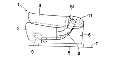
図1〜図4は本発明に係るシートベルトの取付構造の実施形態を示している。図において、1は四輪車両などの車室内に配設される車両用シートのうち、車両後部に設けられるリヤシートであり、このリヤシート1は、図1に示す如く、乗員が着座するシートクッション2と、乗員の背部を受けるシートバック3とを備えている。そして、リヤシート1には、シートクッション2に着座した乗員を保持するシートベルト4が取付けられている。
【0009】
上記リヤシート1は、図3および図4に示す如く、シートバック3が前倒し可能であり、かつシートバック3が前方へ倒れるとシートクッション2が前方かつ下方へスライド移動(チルトダウン)するタイプのシートである。このため、リヤシート1は、シート取付部材のロアレール5およびアッパレール6を介して車体フロア7上に設けられており、アッパレール6は、車体フロア7に固定されたロアレール5上にスライド可能に設置されている。また、シートバック3の下部には、シートクッション2の後部と側面視で略L字状のクッションステー(連接部材)8を介して回動可能に取付けられており、シートクッション2の左右前方側下部には、前部脚9の上端が回動可能にそれぞれ取付けられている。そして、これら前部脚9の下端は、車体フロア7側のアッパレール6に回動可能に取付けられている。
【0010】
また、上記シートバック3の下端には、シートクッション2の後端と回動自在に連結するヒンジ部の延設部10が一体に設けられており、該延設部10は車体フロア7側のアッパレール6に回動可能に取付けられ、シートバック3を前倒しすると、シートクッション2が前方かつ下方へスライド移動するように構成されている。しかも、延設部10には、これを覆うヒンジカバー11が取付けられており、該ヒンジカバー11は、後述のバックルウェビングと延設部10との接触面に配置されている。
【0011】
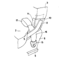
一方、上記シートベルト4は、図1および図2に示す如く、車体側に設けられたリトラクタ(図示せず)よりガイドリング12を経て巻き取り可能に取出され、かつシートクッション2の側部の車体フロア7などに固定されるタングウェビング13と、該タングウェビング13の中間部に設けられるタング(スルータング)14と、一端がアンカプレート15を介して車体フロア7側のアッパレール6に固定されるバックルウェビング16と、該バックルウェビング16の他端に設けられるバックル17とを備えている。バックル17は、ベルト脱着用のロック機構を有しており、当該バックル17にタング14を挿入したり、抜脱したりすることによりシートベルト4を着脱するように構成されている。そして、アンカプレート15は、アッパレール6の外側面に取付けられて固定されている。
【0012】
また、本実施形態のバックルウェビング16は、シートバック3、シートクッション2およびクッションステー8で囲まれた空間部Sに挿通され、その位置がヒンジカバー11とクッション2とクッションステー8とによって規制されており、先端側のバックル17がシートクッション2の上面側に常時配置されるように構成されている。この空間部Sは、アンカプレート15の挿通が可能で、かつバックル17の挿通が不可能な大きさに設定されており、これによってアンカプレート15の取付作業が支障なく行え、かつシートクッション2のスライド移動に伴ってバックル17がシートクッション2から落下しないようになっている。しかも、空間部Sは、ヒンジカバー11の大きさを適切に変更することによって、その大きさが調整可能に構成され、様々な大きさのバックル17に対応できるようになっている。
【0013】
本発明の実施の形態に係る取付構造によって、シートベルト4のバックルウェビング16をシート取付部材に取付けるには、まず、バックルウェビング16を持って一端側のアンカプレート15を空間部Sに挿通させ、この状態で、アンカプレート15をアッパレール6の外側面にボルトなどにより締付けて取付ける。すると、バックルウェビング16は、ヒンジカバー11とクッション2とクッションステー8とによって位置規制され、他端側のバックル17はシートクッション2の上面側に配置されることになり、シートベルト4の取付作業は終了することになる(図1および図2参照)。
【0014】
本発明の実施の形態に係るシートベルト4の取付構造では、バックルウェビング16の一端にアンカプレート15を設け、かつバックルウェビング16の他端にバックル17を設け、アンカプレート15をアッパレール6に取付けると共に、シートバック3、シートクッション2およびクッションステー8で囲まれた空間部Sにバックルウェビング16を挿通し、シートクッション2の上面側にバックル17を配置しているため、前方かつ下方へスライド移動するタイプのリヤシート1のシートバック3を前倒しすることによりシートクッション2が前方および下方へスライド移動しても、バックル17がシートクッション2の下方に脱落することなく、バックル17を常にタング14の差し込み易い位置に置くことができる。したがって、本実施形態の取付構造では、バックル17の脱落防止専用の別部品および別構造を設ける必要がないため、重量およびコストを抑えることができる上、別部品による乗員との接触を避けることができる。
【0015】
また、本実施形態の取付構造では、シートバック3、シートクッション2およびクッションステー8で囲まれた空間部Sを、アンカプレート15の挿通が可能で、かつバックル17の挿通が不可能な大きさに設定しており、しかも、シートバック3の延設部10にヒンジカバー11を設け、ヒンジカバー11の大きさを変更することによって空間部Sの大きさを調整可能に構成しているため、ヒンジカバー11の大きさを適切に選択することにより、様々な大きさのバックル17にも簡単に対応することができる。
【0016】
以上、本発明の実施の形態につき述べたが、本発明は既述の実施の形態に限定されるものではなく、本発明の技術的思想に基づいて各種の変形および変更が可能である。
【0017】
例えば、本発明の取付構造は、図5に示す如く、タングウェビング13にも適用可能であり、この場合、タングウェビング13は、シートバック3、シートクッション2およびクッションステー8で囲まれた空間部Sに挿通され、先端側のタング14がシートクッション2の上面側に常に配置されることになる。したがって、タング14のバックル17への差し込みが容易となる。また、本発明の取付構造は、シート取付部材を、ロアレール5およびアッパレール6によりスライド可能に構成するのでなく、車体フロア7に対して固着しても良い。
【0018】
【発明の効果】
上述の如く、本発明に係るシートベルトの取付構造は、シートクッションとシートバックを備え、シート取付部材を介して車体フロアに対して前記シートバックを回動可能に取付ける一方、前記シートクッションの前方側下部に前部脚の上端を回動可能に取付けると共に、該前部脚の下端を車体フロア側に回動可能に取付け、さらに前記シートクッションの後部を連接部材を介してシートバックの下部に回動可能に取付けることにより、前記シートバックを前倒しすると、前記シートクッションが前方かつ下方へスライド移動する車両用シートに取付けられるものであって、前記シートベルトの一部を構成するウェビングを、前記シートバック、前記シートクッションおよび前記連接部材で囲まれた空間部に挿通し、前記ウェビングの一端に備えたバックルまたはタングを前記シートクッションの上面側に配置すると共に、前記ウェビングの他端に備えたアンカプレートを前記車体フロア側または前記シート取付部材の外側面に取付け、前記空間部は、前記バックルおよび前記タングの挿通が不可能な大きさに設定しているので、シートバックの前倒しやシートクッションのスライド移動等の動作によりバックルまたはタングがシートクッションから落下することを確実に防止し、バックルとタングを互いに差し込み易い位置に常に配置できると共に、バックルやタングの脱落防止専用の別部品および別構造を設ける必要がなくなり、重量増大およびコスト高を抑えることができる。
【図面の簡単な説明】
【図1】本発明の実施の形態に係るシートベルトの取付構造が適用されたリヤシートの全体を示す斜視図である。
【図2】図1におけるX部を拡大して示す斜視図である。
【図3】図1におけるリヤシートのシートバックが起立している状態を示す側面図である。
【図4】図1におけるリヤシートのシートバックが前倒ししている状態を示す側面図である。
【図5】本発明の実施形態の変形例を示すものであり、図2に対応するX部を示す斜視図である。
【図6】従来のシートベルトの取付構造が適用されたリヤシートを示す斜視図である。
【図7】図6における従来例1のY部を拡大して示す斜視図である。
【図8】図6における従来例2のY部を拡大して示す斜視図である。
【図9】図6における従来例3のY部を拡大して示す斜視図である。
【符号の説明】
1 リヤシート
2 シートクッション
3 シートバック
4 シートベルト
5 ロアレール
6 アッパレール
7 車体フロア
8 クッションステー(連接部材)
9 前部脚
10 延設部
11 ヒンジカバー
12 ガイドリング
13 タングウェビング
14 タング
15 アンカプレート
16 バックルウェビング
17 バックル
S 空間部[0001]
BACKGROUND OF THE INVENTION
The present invention particularly relates to a seat belt mounting structure provided on a rear seat or the like of a four-wheel vehicle.
[0002]
[Prior art]
Conventionally, a
[0003]
Therefore, in the conventional
[0004]
[Problems to be solved by the invention]
As described above, in the conventional
[0005]
The present invention has been made in view of such a situation. The purpose of the present invention is to reliably prevent the buckle or tongue from falling off without using separate parts or a separate structure. An object of the present invention is to provide a seat belt mounting structure that can be arranged at a position where it can be easily inserted.
[0006]
[Means for Solving the Problems]
In order to solve the above-described problems of the prior art, in the present invention, a seat cushion and a seat back are provided, and the seat back is rotatably attached to a vehicle body floor via a seat attachment member. The upper end of the front leg is pivotably attached to the lower front side of the vehicle, the lower end of the front leg is pivotally attached to the vehicle floor, and the rear part of the seat cushion is connected to the seat back via a connecting member. A part of the seat belt is configured in a seat belt mounting structure in which the seat cushion is attached to a vehicle seat that slides forward and downward when the seat back is tilted forward by being pivotably attached to the lower part. interpolation webbing, the seat back, the space surrounded by the seat cushion and the connecting member And, together with placing the buckle or tongue provided on one end of the webbing to the top side of the seat cushion, mounting the anchor plate with the other end of the webbing on the outer surface of the vehicle body floor side or the seat mounting member, The space portion is set to a size in which the buckle and the tongue cannot be inserted .
[0007]
DETAILED DESCRIPTION OF THE INVENTION
Hereinafter, the present invention will be described in detail based on illustrated embodiments.
[0008]
1 to 4 show an embodiment of a seat belt mounting structure according to the present invention. In the figure,
[0009]
As shown in FIGS. 3 and 4, the
[0010]
Further, an extending
[0011]
On the other hand, as shown in FIGS. 1 and 2, the seat belt 4 is unwound from a retractor (not shown) provided on the vehicle body side via a
[0012]
Further, the
[0013]
In order to attach the
[0014]
In the seat belt 4 mounting structure according to the embodiment of the present invention, the
[0015]
Further, in the mounting structure of the present embodiment, the space portion S surrounded by the seat back 3, the
[0016]
Although the embodiments of the present invention have been described above, the present invention is not limited to the above-described embodiments, and various modifications and changes can be made based on the technical idea of the present invention.
[0017]
For example, as shown in FIG. 5, the mounting structure of the present invention can also be applied to a
[0018]
【The invention's effect】
As described above, the seat belt mounting structure according to the present invention includes a seat cushion and a seat back, and the seat back is pivotably mounted to the vehicle body floor via the seat mounting member, while the front of the seat cushion. The upper end of the front leg is pivotably attached to the side lower part, the lower end of the front leg is pivotally attached to the vehicle body floor side, and the rear part of the seat cushion is connected to the lower part of the seat back via a connecting member. When the seat back is tilted forward by being pivotably attached , the seat cushion is attached to a vehicle seat that slides forward and downward, and a webbing that constitutes a part of the seat belt includes: seat back, the inserted through the space surrounded by the seat cushion and the connecting member, one end of the webbing The example was buckle or tongue as well as disposed on the upper surface side of the seat cushion, mounting the anchor plate with the other end of the webbing on the outer surface of the vehicle body floor side or the seat mounting member, the space portion, said buckle and The size of the tongue is set so that it cannot be inserted, so that the buckle or tongue can be reliably prevented from falling off the seat cushion by moving the seat back forward or sliding the seat cushion. Can be always placed at positions where they can be easily inserted into each other, and it is not necessary to provide a separate part and a separate structure dedicated to preventing the buckle and tongue from falling off, thereby suppressing an increase in weight and cost.
[Brief description of the drawings]
FIG. 1 is a perspective view showing an entire rear seat to which a seat belt mounting structure according to an embodiment of the present invention is applied.
2 is an enlarged perspective view showing a portion X in FIG. 1. FIG.
FIG. 3 is a side view showing a state in which the seat back of the rear seat in FIG. 1 is raised.
4 is a side view showing a state where the seat back of the rear seat in FIG. 1 is tilted forward.
FIG. 5 is a perspective view showing a portion X corresponding to FIG. 2, showing a modification of the embodiment of the present invention.
FIG. 6 is a perspective view showing a rear seat to which a conventional seat belt mounting structure is applied.
7 is an enlarged perspective view showing a Y portion of Conventional Example 1 in FIG. 6. FIG.
8 is an enlarged perspective view showing a Y portion of Conventional Example 2 in FIG.
9 is an enlarged perspective view showing a Y portion of Conventional Example 3 in FIG. 6;
[Explanation of symbols]
1
9
Claims (3)
Priority Applications (1)
| Application Number | Priority Date | Filing Date | Title |
|---|---|---|---|
| JP2001275913A JP4006675B2 (en) | 2001-09-12 | 2001-09-12 | Seat belt mounting structure |
Applications Claiming Priority (1)
| Application Number | Priority Date | Filing Date | Title |
|---|---|---|---|
| JP2001275913A JP4006675B2 (en) | 2001-09-12 | 2001-09-12 | Seat belt mounting structure |
Publications (2)
| Publication Number | Publication Date |
|---|---|
| JP2003080988A JP2003080988A (en) | 2003-03-19 |
| JP4006675B2 true JP4006675B2 (en) | 2007-11-14 |
Family
ID=19100696
Family Applications (1)
| Application Number | Title | Priority Date | Filing Date |
|---|---|---|---|
| JP2001275913A Expired - Fee Related JP4006675B2 (en) | 2001-09-12 | 2001-09-12 | Seat belt mounting structure |
Country Status (1)
| Country | Link |
|---|---|
| JP (1) | JP4006675B2 (en) |
Families Citing this family (5)
| Publication number | Priority date | Publication date | Assignee | Title |
|---|---|---|---|---|
| JP4569386B2 (en) * | 2005-05-27 | 2010-10-27 | マツダ株式会社 | Vehicle seat storage structure |
| JP4671285B2 (en) | 2005-10-31 | 2011-04-13 | タカタ株式会社 | Vehicle seat belt |
| JP4176118B2 (en) | 2006-07-31 | 2008-11-05 | トヨタ自動車株式会社 | Vehicle seat device |
| JP5487727B2 (en) * | 2009-05-28 | 2014-05-07 | トヨタ紡織株式会社 | Vehicle seat fall prevention structure |
| JP6148220B2 (en) * | 2014-10-17 | 2017-06-14 | テイ・エス テック株式会社 | Vehicle seat |
-
2001
- 2001-09-12 JP JP2001275913A patent/JP4006675B2/en not_active Expired - Fee Related
Also Published As
| Publication number | Publication date |
|---|---|
| JP2003080988A (en) | 2003-03-19 |
Similar Documents
| Publication | Publication Date | Title |
|---|---|---|
| EP0599501B1 (en) | Vehicle seat assembly with integral child seat | |
| US5282667A (en) | Vehicle seat assembly with integral child seat | |
| US6089659A (en) | Headrest secured automobile seat cover | |
| EP0901935B1 (en) | Child seat anchorage | |
| US5700054A (en) | Vehicle seat assembly including integral child restraint seat | |
| US6616235B1 (en) | Seat assembly with integral head/neck rest | |
| US7887140B1 (en) | Automobile seat with integral child safety restraining assembly | |
| US6736456B2 (en) | Seat apparatus for automobile | |
| JPH0999767A (en) | Headrest housing mechanism of seat for vehicle | |
| EP0671291B1 (en) | Vehicle seat for children | |
| US20120139304A1 (en) | Vehicle seat with oxygen tank storage | |
| US5332284A (en) | Passenger car seat assembly with integral child seat | |
| JP3936166B2 (en) | Vehicle seat structure | |
| JP4006675B2 (en) | Seat belt mounting structure | |
| JPH07232580A (en) | Seat device for vehicle | |
| JP3972974B2 (en) | Automotive seat | |
| JPH074999Y2 (en) | Hinge cover for vehicle seat | |
| JP4421465B2 (en) | Vehicle seat | |
| US20090066129A1 (en) | Rigid Mounting Device for a Child Safety Seat with a hook connection | |
| KR19980054554A (en) | Removable Headrests for Cars | |
| JPH0986340A (en) | Seat belt device for child | |
| JP2963977B2 (en) | Foldable car seat | |
| JP2004195079A (en) | Device for preventing mounted object from falling | |
| JP4090679B2 (en) | Separate rear seat | |
| JP4280054B2 (en) | Mounted item fall prevention device |
Legal Events
| Date | Code | Title | Description |
|---|---|---|---|
| A621 | Written request for application examination |
Free format text: JAPANESE INTERMEDIATE CODE: A621 Effective date: 20040608 |
|
| A131 | Notification of reasons for refusal |
Free format text: JAPANESE INTERMEDIATE CODE: A131 Effective date: 20070601 |
|
| A521 | Written amendment |
Free format text: JAPANESE INTERMEDIATE CODE: A523 Effective date: 20070629 |
|
| TRDD | Decision of grant or rejection written | ||
| A01 | Written decision to grant a patent or to grant a registration (utility model) |
Free format text: JAPANESE INTERMEDIATE CODE: A01 Effective date: 20070803 |
|
| A61 | First payment of annual fees (during grant procedure) |
Free format text: JAPANESE INTERMEDIATE CODE: A61 Effective date: 20070816 |
|
| FPAY | Renewal fee payment (event date is renewal date of database) |
Free format text: PAYMENT UNTIL: 20100907 Year of fee payment: 3 |
|
| FPAY | Renewal fee payment (event date is renewal date of database) |
Free format text: PAYMENT UNTIL: 20100907 Year of fee payment: 3 |
|
| FPAY | Renewal fee payment (event date is renewal date of database) |
Free format text: PAYMENT UNTIL: 20110907 Year of fee payment: 4 |
|
| FPAY | Renewal fee payment (event date is renewal date of database) |
Free format text: PAYMENT UNTIL: 20110907 Year of fee payment: 4 |
|
| FPAY | Renewal fee payment (event date is renewal date of database) |
Free format text: PAYMENT UNTIL: 20120907 Year of fee payment: 5 |
|
| FPAY | Renewal fee payment (event date is renewal date of database) |
Free format text: PAYMENT UNTIL: 20120907 Year of fee payment: 5 |
|
| FPAY | Renewal fee payment (event date is renewal date of database) |
Free format text: PAYMENT UNTIL: 20130907 Year of fee payment: 6 |
|
| FPAY | Renewal fee payment (event date is renewal date of database) |
Free format text: PAYMENT UNTIL: 20130907 Year of fee payment: 6 |
|
| FPAY | Renewal fee payment (event date is renewal date of database) |
Free format text: PAYMENT UNTIL: 20140907 Year of fee payment: 7 |
|
| LAPS | Cancellation because of no payment of annual fees |