EP1944171A2 - Bildaufzeichnungsvorrichtung - Google Patents
Bildaufzeichnungsvorrichtung Download PDFInfo
- Publication number
- EP1944171A2 EP1944171A2 EP08000299A EP08000299A EP1944171A2 EP 1944171 A2 EP1944171 A2 EP 1944171A2 EP 08000299 A EP08000299 A EP 08000299A EP 08000299 A EP08000299 A EP 08000299A EP 1944171 A2 EP1944171 A2 EP 1944171A2
- Authority
- EP
- European Patent Office
- Prior art keywords
- image recording
- gas
- scanning direction
- primary scanning
- laser
- Prior art date
- Legal status (The legal status is an assumption and is not a legal conclusion. Google has not performed a legal analysis and makes no representation as to the accuracy of the status listed.)
- Granted
Links
Images



Classifications
-
- B—PERFORMING OPERATIONS; TRANSPORTING
- B41—PRINTING; LINING MACHINES; TYPEWRITERS; STAMPS
- B41J—TYPEWRITERS; SELECTIVE PRINTING MECHANISMS, i.e. MECHANISMS PRINTING OTHERWISE THAN FROM A FORME; CORRECTION OF TYPOGRAPHICAL ERRORS
- B41J29/00—Details of, or accessories for, typewriters or selective printing mechanisms not otherwise provided for
- B41J29/377—Cooling or ventilating arrangements
-
- B—PERFORMING OPERATIONS; TRANSPORTING
- B41—PRINTING; LINING MACHINES; TYPEWRITERS; STAMPS
- B41J—TYPEWRITERS; SELECTIVE PRINTING MECHANISMS, i.e. MECHANISMS PRINTING OTHERWISE THAN FROM A FORME; CORRECTION OF TYPOGRAPHICAL ERRORS
- B41J2/00—Typewriters or selective printing mechanisms characterised by the printing or marking process for which they are designed
- B41J2/435—Typewriters or selective printing mechanisms characterised by the printing or marking process for which they are designed characterised by selective application of radiation to a printing material or impression-transfer material
- B41J2/447—Typewriters or selective printing mechanisms characterised by the printing or marking process for which they are designed characterised by selective application of radiation to a printing material or impression-transfer material using arrays of radiation sources
- B41J2/45—Typewriters or selective printing mechanisms characterised by the printing or marking process for which they are designed characterised by selective application of radiation to a printing material or impression-transfer material using arrays of radiation sources using light-emitting diode [LED] or laser arrays
- B41J2/451—Special optical means therefor, e.g. lenses, mirrors, focusing means
Definitions
- This invention relates to an image recording apparatus for recording an image on an image recording medium which generates gas, dust and the like through a thermal reaction.
- the object of this invention is to provide an image recording apparatus in which gas and the like generated by laser irradiation do not seriously lower image quality even if the gas and the like re-adhere to the surface of an image recording medium.
- an image recording apparatus comprising a holder member for holding an image recording medium mounted on a surface thereof an image recording device for emitting light beams modulated by image signals toward the image recording medium; a primary scanning device for causing the light beams to scan the image recording medium in a primary scanning direction by moving the light beams relative to the holder member; a secondary scanning device for moving the image recording device in a direction perpendicular to the primary scanning direction; and a gas blowing device for blowing out a first gas in a predetermined direction to blow away a second gas generated from the image recording medium irradiated by the light beams; wherein the image recording device has a plurality of light sources arranged in a direction intersecting the primary scanning direction; the light sources being arranged in such a positional relationship that each light source is located upstream, in the primary scanning direction, of a different light source located adjacent thereto and downstream thereof in the gas blowing direction.
- the gas and the like generated by a light beam emitted from a certain light source is driven by a different gas blown out to move over an area exposed by a different light source adjoining that certain light source.
- Most of the gas and the like moved over the exposed area adhere to this area, without flowing over areas downstream thereof the gas blowing direction. Consequently, the surface of the image recording medium has no area where the gas and the like adhere locally, with little likelihood of variations in the adhesion of the gas and the like.
- the holder member is a cylindrical member around which the image recording medium is wrapped
- the primary scanning device is a motor for rotating the cylindrical member
- the image recording medium is a letterpress medium
- the light sources are arranged two-dimensionally.
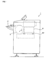
- Fig. 1 is a see-through side view of an image recording apparatus 1 which records an image on a flexo-digital plate P.
- An unexposed flexo-digital plate P (hereinafter abbreviated as plate P) is introduced from outside through an opening 2 into the image recording apparatus 1, and is wrapped around a drum 3.
- the drum 3 is rotatable in the direction of arrow "r" by a rotating mechanism not shown.
- a recording head 4 is disposed opposite the drum 3.
- the recording head 4 is movable along the axis of rotation of the drum 3 (in the direction normal to the plane of Fig. 1 ) by a secondary scanning device 4Y.
- the drum 3 is rotated while laser light modulated by image signals is emitted from the recording head 4 toward the surface of plate P, whereby the surface of plate P undergoes primary scanning action of the modulated laser light.
- the surface of plate P undergoes secondary scanning action of the modulated laser light when the recording head 4 is moved along the axis of rotation of the drum 3 synchronously with rotation of the drum 3.
- the scanning directions will be referred to as secondary scanning direction X and primary scanning direction Y.
- the drum 3 is a hollow cylindrical member having an inner chamber.
- the inner chamber is connected through piping to a vacuum pump, not shown, disposed outside the drum 3.
- Fig. 2 is a side view showing an outline of the recording head 4.
- Fig. 3 is a top view of the recording head 4 and drum 3.
- Fig. 4 is a front view of the recording head 4 seen from the drum 3.
- the recording head 4 includes a housing 41 with a laser source 42 mounted therein for emitting laser light.
- the laser light emitted from the laser source 42 with the action of a lens 43, forms an image at a point EP on the surface of the drum 3 (actually, on the plate P wrapped around the drum 3).
- a point EP on the surface of the drum 3 (actually, on the plate P wrapped around the drum 3).
- gas and dust will be generated.
- an air blowoff pipe 44, a case 45 and a gas suction pipe 46 are arranged on the front of the housing 41.
- the air blowoff pipe 44 blows high-speed air purified by a filter, from above the laser source 42 (that is, from downstream of the laser source 42 in the primary scanning direction Y) and from upstream in the secondary scanning direction X toward the laser irradiation point EP. This produces an airflow in a direction turned approximately 45 degrees clockwise from the primary scanning direction Y in Fig. 4 , which blows away the gas and the like generating from the plate P.
- the case 45 is a box-like member which prevents further diffusion of the diffused gas, and has an opening formed in a part of its surface opposed to the drum 3. That is, the hatched portion 45a in Fig. 4 is the opening of the case 45.
- the gas suction pipe 46 is connected to the case 45 in a position thereof downstream in the secondary scanning direction X.
- Fig. 5 is a developed view of the surface 31 of the drum 3.
- Fig. 5 shows, for reference, an X-axis of coordinates corresponding to the secondary scanning direction X, and a Y-axis of coordinates corresponding to the primary scanning direction Y.
- Fig. 5 shows two plates, i.e. a small size plate P1 and a large size plate P2, by way of example.
- the small plate P1 is a rectangle having vertices at point (x2, y1), point (x2, y5), point (x6, y5) and point (x6, y1).
- the large plate P2 is a rectangle having vertices at point (x1, y1), point (x1, y6), point (x6, y6) and point (x6, y1).
- suction grooves L1-L15 are formed in the drum surface 31 to have different angles of inclination relative to the secondary scanning direction X.
- the suction grooves L1-L15 extend from the same position in the primary scanning direction Y (i.e. from position y2 of Y coordinates), and from different positions in the secondary scanning direction X (between position x4 and position x5 inclusive of X coordinates).
- the suction grooves L1-L15 have suction bores H1-H15 formed in predetermined bottom positions thereof, respectively, for communication with the inner chamber of the drum 3.
- the suction grooves L2-L5 and L7-L14 and suction bores H2-H5 and H7-H14 are not affixed with the reference signs to avoid complication of the illustration.
- the suction groove L1 extends parallel to the secondary scanning direction X.
- the suction bore H1 is formed in the position, the most downstream in the secondary scanning direction X, of the suction groove L1.
- the suction groove L6 extends in a direction inclined approximately 45 degrees counterclockwise relative to the secondary scanning direction X.
- the suction bore H6 is formed in the position, the most downstream in the secondary scanning direction X, of the suction groove L6.
- the suction groove L15 extends parallel to the primary scanning direction Y.
- the suction grooves L2-L15 other than the suction groove L1 are formed to cross the secondary scanning direction X at different angles, respectively.
- the suction bores H2-H15 are formed in the positions, the most upstream in the primary scanning direction Y, i.e. the nearest to origin
- the position of coordinates (x6, y1) is used as reference for attaching any size plate P to the drum surface 31.
- the lower left point of plate P is common to all plate sizes, and an increase in the plate size entails an enlargement in the direction -X counter to the secondary scanning direction X or in the primary scanning direction Y.
- the position identified by coordinates (x6, y1) is called a reference position for attaching plates P.
- Fig. 5 schematically shows how the gas G generating from the laser irradiation point EP is driven upstream of the point EP in the primary scanning direction Y, and downstream of the point EP in the secondary scanning direction X, by the air blown from the air blowoff pipe 44.
- the laser source 42 of this image recording apparatus 1 is a multichannel type light source having a plurality of semiconductor lasers arranged two-dimensionally (e.g. in a lattice arrangement of six semiconductor lasers in total, consisting of three rows in the primary scanning direction and two rows in the secondary scanning direction).
- Fig. 6 is a view showing an example of arrangement of a plurality of semiconductor lasers ch in the laser source 42.
- a plurality of semiconductor lasers ch11, 12 and 13 located upstream in the secondary scanning direction X form a first row of light sources inclined relative to the primary scanning direction Y.
- a plurality of semiconductor laser ch21, 22 and 23 located downstream in the secondary scanning direction X form a second row of light sources inclined relative to the primary scanning direction Y.
- semiconductor lasers ch13 and 23, located most downstream in the primary scanning direction Y, in the respective rows of light sources will emit light first.
- the remaining semiconductor lasers ch11, 12, 21 and 22 will successively emit light, under timing control, after delays corresponding to their distances from these lasers ch13 and ch23 in the primary scanning direction.
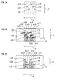
- Fig. 7A shows an arrangement of semiconductor laser light source images (i11, i12, i13, i21, i22 and i23) formed on the plate P by laser beams emitted from the plurality of semiconductor lasers ch.
- the light source images i11, i12 and i13 upstream in the secondary scanning direction X are images formed on the surface of plate P by the light beams emitted from the semiconductor laser sources ch11, 12 and 13. These light source images i11, i12 and i13 form a first row of light source images inclined relative to the primary scanning direction Y.
- the light source images i21, i22 and i23 downstream in the secondary scanning direction X are images formed on the surface of plate P by the light beams emitted from the semiconductor laser sources ch21, 22 and 23. These light source images i21, i22 and i23 form a second row of light source images inclined relative to the primary scanning direction Y.
- Fig. 7B is a schematic view illustrating a positional relationship between scan areas (a11, a12, a13, a21, a22 and a23) scanned by the semiconductor lasers ch and the light source images (i11, i12, i13, i21, i22 and i23).
- the hatched portions of the scan areas (a11, a12, a13, a21, a22 and a23) are those already irradiated with the laser beams by the time of illustration.
- Gas and dust are generated from the light source image i11 of the semiconductor laser ch11.
- the air blowoff pipe 44 described hereinbefore causes the gas G11 to flow over the area a12 already irradiated by the laser beam from the laser source ch12, and located downstream in an air blowing direction "d".
- This plate P has such a property that is adsorptivity of gas and the like changes as a result of laser irradiation. That is, adhesion increases in laser-irradiated areas of this plate P. Therefore, a laser-irradiated area will more readily adsorb gas flowing thereover than an unexposed area.
- Gas G12 generated from the light source image i12 is driven to flow over the scan area a13 irradiated with the laser light. Since the gas G12 flows over the laser-irradiated portion of the scan area a13, this portion adsorbs part of the gas G12. Only the remaining part of the gas G12 is collected through the opening 45a into the case 45.
- Gas G13 generated from the light source image i13 flows over unexposed portions of the areas a21 and a22. Since the gas adsorptivity of these portions is almost the same and as low as before image recording, most of the gas G13 is collected through the opening 45a into the case 45 without re-adhering to the surface of plate P.
- Re-adhesion of the gas generated from the plate P as a result of laser emission from the second row of light sources is similar to the above, and will not be described.
- Fig. 7C is a view showing a state of re-adhesion of the gas and the like to the plate P.
- the scan area a11 the most upstream in the air blowing direction "d” is free from adhesion of the gas generated by laser emission from the other light sources.
- the scan area a12 next upstream in the air blowing direction “d” has, adhering thereto, only the gas G11 generated immediately upstream in the air blowing direction "d” by laser emission from the semiconductor laser ch11. Further, the scan area a13 has, adhering thereto, only the gas G12 generated immediately upstream in the air blowing direction "d” by laser emission from the semiconductor laser chl2.
- the scan area a21 formed most upstream in the air blowing direction "d" by the semiconductor laser ch21 has the gas from the scan areas of the other semiconductor lasers attached thereto before image formation by the semiconductor laser ch21.
- these adhering elements are removed by laser emission from the semiconductor laser ch21, and therefore have little or no influence.
- the scan areas a22 and a23 undergo, only once, adhesion thereto of the gas from the scan areas of the other semiconductor lasers, as do the scan areas a12 and a13.
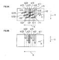
- Figs. 8 and 9 are comparative diagrams illustrating a state of re-adhesion of gas and the like at the time of rotating the drum 3 in a direction -r opposite to the case shown in Figs. 6 and 7 .
- the primary scanning direction also is opposite to the direction shown in Figs. 6 and 7 (to distinguish the opposite directions, the primary scanning direction being referenced -Y in Figs. 8 and 9 ).
- the secondary scanning direction X and air blowing direction "d" are the same as those in Figs. 6 and 7 .
- the plurality of semiconductor lasers ch11, 12 and 13 located upstream in the secondary scanning direction X form a first row of light sources inclined relative to the primary scanning direction - Y.
- the plurality of semiconductor laser ch21, 22 and 23 located downstream in the secondary scanning direction X form a second row of light sources inclined relative to the primary scanning direction -Y.
- the semiconductor laser ch11 (ch21) located the most upstream in the air blowing direction "d" among the plurality of semiconductor lasers ch belonging to each row is located the most downstream in the primary scanning direction - Y.
- Fig. 9A is a schematic view showing images i11, i12, i13, i21, i22 and i23 of the plurality of semiconductor lasers ch11, ch12, ch13, ch21, ch22, and ch23, and gas, dust and the like (G11, G12, G13, G21, G22 and G23) generating from the light source images.
- Gas G11 generated from the light source image i11 is driven by the air blowoff pipe 44 described hereinbefore to flow over an unexposed portion of the scan area a12 located downstream in the air blowing direction "d". Thus, the gas G11 flows further downstream in the air blowing direction "d" without being adsorbed to the scan area a12.
- Gas G12 generated from the light source image i12 is driven to flow over the scan areas a13 and a21. While the former is an unexposed portion, the latter is a portion irradiated by the laser beam emitted from the semiconductor laser ch21 and therefore easily adsorptive of gas and the like. Thus, part of the gas G12 is adsorbed to the laser-irradiated portion of the scan area a21, and the remainder is collected through the opening 45a into the case 45.
- Gas G13 generated from the light source image i13 flows over the laser-irradiated portion of the scan size a21. This portion adsorbs part of the gas G13, and the remainder is collected through the opening 45a into the case 45.
- the gas and the like generated from the plurality of light source images i11, i12 and i13 belonging to the first row of light source images are adsorbed in the largest quantity to the laser-irradiated portion of the scan area a21 corresponding to the light source ch21 and located the most upstream in the air blowing direction "d", and are little adsorbed to other portions.
- the largest quantity of gas and the like re-adheres to the scan area a21 among the scan areas a11, 12, 13, 21, 22 and 23.
- Fig. 9B is a view showing a state of re-adhesion of the gas and so on to the plate P in the comparative example.
Landscapes
- Physics & Mathematics (AREA)
- Optics & Photonics (AREA)
- Health & Medical Sciences (AREA)
- General Health & Medical Sciences (AREA)
- Toxicology (AREA)
- Exposure And Positioning Against Photoresist Photosensitive Materials (AREA)
- Manufacture Or Reproduction Of Printing Formes (AREA)
- Mechanical Optical Scanning Systems (AREA)
- Laser Beam Printer (AREA)
- Semiconductor Lasers (AREA)
- Facsimile Scanning Arrangements (AREA)
- Photographic Developing Apparatuses (AREA)
Applications Claiming Priority (1)
| Application Number | Priority Date | Filing Date | Title |
|---|---|---|---|
| JP2007004068A JP4859681B2 (ja) | 2007-01-12 | 2007-01-12 | 画像記録装置 |
Publications (3)
| Publication Number | Publication Date |
|---|---|
| EP1944171A2 true EP1944171A2 (de) | 2008-07-16 |
| EP1944171A3 EP1944171A3 (de) | 2008-07-23 |
| EP1944171B1 EP1944171B1 (de) | 2009-05-13 |
Family
ID=39322403
Family Applications (1)
| Application Number | Title | Priority Date | Filing Date |
|---|---|---|---|
| EP08000299A Not-in-force EP1944171B1 (de) | 2007-01-12 | 2008-01-09 | Bildaufzeichnungsvorrichtung |
Country Status (6)
| Country | Link |
|---|---|
| US (1) | US7924302B2 (de) |
| EP (1) | EP1944171B1 (de) |
| JP (1) | JP4859681B2 (de) |
| CN (1) | CN101219610B (de) |
| AT (1) | ATE431254T1 (de) |
| DE (1) | DE602008000012D1 (de) |
Family Cites Families (12)
| Publication number | Priority date | Publication date | Assignee | Title |
|---|---|---|---|---|
| CA1099435A (en) * | 1971-04-01 | 1981-04-14 | Gwendyline Y. Y. T. Chen | Photosensitive block copolymer composition and elements |
| JPH0980343A (ja) * | 1995-07-10 | 1997-03-28 | Fuji Photo Film Co Ltd | 画像走査装置のゴミ付着防止装置 |
| US5729793A (en) | 1995-07-10 | 1998-03-17 | Fuji Photo Film Co. Ltd. | Dust adhesion prevention system for image scanning system |
| JP3838697B2 (ja) | 1996-05-28 | 2006-10-25 | 富士写真フイルム株式会社 | 画像記録装置 |
| US6400389B1 (en) * | 2000-01-25 | 2002-06-04 | Eastman Kodak Company | Apparatus for laser marking indicia on a photosensitive web |
| US6494965B1 (en) * | 2000-05-30 | 2002-12-17 | Creo Products Inc. | Method and apparatus for removal of laser ablation byproducts |
| DE10323112A1 (de) * | 2002-05-28 | 2003-12-11 | Heidelberger Druckmasch Ag | Vorrichtung zum Herstellen einer Druckform |
| US7230636B2 (en) | 2003-03-10 | 2007-06-12 | Dainippon Screen Mfg. Co., Ltd. | Image recording apparatus with jet and suction |
| JP2004294740A (ja) * | 2003-03-27 | 2004-10-21 | Dainippon Screen Mfg Co Ltd | 画像記録装置 |
| JP4354219B2 (ja) | 2003-06-20 | 2009-10-28 | 大日本スクリーン製造株式会社 | 画像記録装置 |
| JP2005266467A (ja) * | 2004-03-19 | 2005-09-29 | Fuji Photo Film Co Ltd | 画像露光装置および画像露光方法 |
| JP2007293269A (ja) | 2006-03-28 | 2007-11-08 | Dainippon Screen Mfg Co Ltd | 画像記録装置 |
-
2007
- 2007-01-12 JP JP2007004068A patent/JP4859681B2/ja not_active Expired - Fee Related
- 2007-12-29 CN CN2007103076074A patent/CN101219610B/zh not_active Expired - Fee Related
-
2008
- 2008-01-03 US US12/003,885 patent/US7924302B2/en not_active Expired - Fee Related
- 2008-01-09 AT AT08000299T patent/ATE431254T1/de not_active IP Right Cessation
- 2008-01-09 DE DE602008000012T patent/DE602008000012D1/de active Active
- 2008-01-09 EP EP08000299A patent/EP1944171B1/de not_active Not-in-force
Also Published As
| Publication number | Publication date |
|---|---|
| CN101219610B (zh) | 2010-06-23 |
| US7924302B2 (en) | 2011-04-12 |
| DE602008000012D1 (de) | 2009-06-25 |
| JP2008170746A (ja) | 2008-07-24 |
| US20080170115A1 (en) | 2008-07-17 |
| EP1944171B1 (de) | 2009-05-13 |
| JP4859681B2 (ja) | 2012-01-25 |
| CN101219610A (zh) | 2008-07-16 |
| EP1944171A3 (de) | 2008-07-23 |
| ATE431254T1 (de) | 2009-05-15 |
Similar Documents
| Publication | Publication Date | Title |
|---|---|---|
| KR100564094B1 (ko) | 진공식 파편 제거 시스템 | |
| US7220975B2 (en) | Mask-making member and its production method, mask and its making method, exposure process, and fabrication method of semiconductor device | |
| US7795597B2 (en) | Deflector array, exposure apparatus, and device manufacturing method | |
| JP4388576B2 (ja) | 形状測定装置 | |
| US6328473B1 (en) | Static air-bearing and stage apparatus using the bearing and optical apparatus using the stage apparatus | |
| US6717159B2 (en) | Low distortion kinematic reticle support | |
| US5434424A (en) | Spinning reticle scanning projection lithography exposure system and method | |
| EP1944171B1 (de) | Bildaufzeichnungsvorrichtung | |
| EP2402111A2 (de) | Vorrichtung zur Entfernung eines dünnen Schichtes | |
| JP2008027686A5 (de) | ||
| JP2002305138A (ja) | 露光装置および露光方法 | |
| JP4086651B2 (ja) | 露光装置及び基板保持装置 | |
| CN1160762C (zh) | 电子束曝光掩模、曝光方法和设备及半导体器件制造方法 | |
| TWI815117B (zh) | 多荷電粒子束照射裝置及多荷電粒子束照射方法 | |
| JP6640040B2 (ja) | 伝熱板および描画装置 | |
| JP7617770B2 (ja) | 洗浄装置、洗浄方法、および、半導体装置の製造方法 | |
| CN1172973A (zh) | 多束电子光刻系统的电子柱光学器件 | |
| EP2034362B1 (de) | Bildaufzeichnungsvorrichtung | |
| JPH10289844A (ja) | 荷電粒子ビーム露光方法及びシステム | |
| JPS6371852A (ja) | 組立装置 | |
| CN1306226A (zh) | 曝光装置 | |
| TW202522126A (zh) | 光學裝置以及描繪裝置 | |
| WO2012137785A1 (ja) | マイクロレンズアレイを使用した露光装置 | |
| JP2006041543A (ja) | リソグラフィにおいて使用するためのレチクルグリッパバリヤシステム | |
| JP2011075742A (ja) | パターン描画装置および光源 |
Legal Events
| Date | Code | Title | Description |
|---|---|---|---|
| PUAI | Public reference made under article 153(3) epc to a published international application that has entered the european phase |
Free format text: ORIGINAL CODE: 0009012 |
|
| PUAL | Search report despatched |
Free format text: ORIGINAL CODE: 0009013 |
|
| AK | Designated contracting states |
Kind code of ref document: A2 Designated state(s): AT BE BG CH CY CZ DE DK EE ES FI FR GB GR HR HU IE IS IT LI LT LU LV MC MT NL NO PL PT RO SE SI SK TR |
|
| AX | Request for extension of the european patent |
Extension state: AL BA MK RS |
|
| AK | Designated contracting states |
Kind code of ref document: A3 Designated state(s): AT BE BG CH CY CZ DE DK EE ES FI FR GB GR HR HU IE IS IT LI LT LU LV MC MT NL NO PL PT RO SE SI SK TR |
|
| AX | Request for extension of the european patent |
Extension state: AL BA MK RS |
|
| 17P | Request for examination filed |
Effective date: 20081024 |
|
| GRAP | Despatch of communication of intention to grant a patent |
Free format text: ORIGINAL CODE: EPIDOSNIGR1 |
|
| AKX | Designation fees paid |
Designated state(s): AT BE BG CH CY CZ DE DK EE ES FI FR GB GR HR HU IE IS IT LI LT LU LV MC MT NL NO PL PT RO SE SI SK TR |
|
| GRAS | Grant fee paid |
Free format text: ORIGINAL CODE: EPIDOSNIGR3 |
|
| GRAA | (expected) grant |
Free format text: ORIGINAL CODE: 0009210 |
|
| AK | Designated contracting states |
Kind code of ref document: B1 Designated state(s): AT BE BG CH CY CZ DE DK EE ES FI FR GB GR HR HU IE IS IT LI LT LU LV MC MT NL NO PL PT RO SE SI SK TR |
|
| REG | Reference to a national code |
Ref country code: GB Ref legal event code: FG4D |
|
| REG | Reference to a national code |
Ref country code: CH Ref legal event code: EP |
|
| REG | Reference to a national code |
Ref country code: IE Ref legal event code: FG4D |
|
| REF | Corresponds to: |
Ref document number: 602008000012 Country of ref document: DE Date of ref document: 20090625 Kind code of ref document: P |
|
| PG25 | Lapsed in a contracting state [announced via postgrant information from national office to epo] |
Ref country code: ES Free format text: LAPSE BECAUSE OF FAILURE TO SUBMIT A TRANSLATION OF THE DESCRIPTION OR TO PAY THE FEE WITHIN THE PRESCRIBED TIME-LIMIT Effective date: 20090824 Ref country code: AT Free format text: LAPSE BECAUSE OF FAILURE TO SUBMIT A TRANSLATION OF THE DESCRIPTION OR TO PAY THE FEE WITHIN THE PRESCRIBED TIME-LIMIT Effective date: 20090513 Ref country code: FI Free format text: LAPSE BECAUSE OF FAILURE TO SUBMIT A TRANSLATION OF THE DESCRIPTION OR TO PAY THE FEE WITHIN THE PRESCRIBED TIME-LIMIT Effective date: 20090513 Ref country code: NO Free format text: LAPSE BECAUSE OF FAILURE TO SUBMIT A TRANSLATION OF THE DESCRIPTION OR TO PAY THE FEE WITHIN THE PRESCRIBED TIME-LIMIT Effective date: 20090813 Ref country code: LT Free format text: LAPSE BECAUSE OF FAILURE TO SUBMIT A TRANSLATION OF THE DESCRIPTION OR TO PAY THE FEE WITHIN THE PRESCRIBED TIME-LIMIT Effective date: 20090513 |
|
| NLV1 | Nl: lapsed or annulled due to failure to fulfill the requirements of art. 29p and 29m of the patents act | ||
| PG25 | Lapsed in a contracting state [announced via postgrant information from national office to epo] |
Ref country code: SI Free format text: LAPSE BECAUSE OF FAILURE TO SUBMIT A TRANSLATION OF THE DESCRIPTION OR TO PAY THE FEE WITHIN THE PRESCRIBED TIME-LIMIT Effective date: 20090513 Ref country code: PL Free format text: LAPSE BECAUSE OF FAILURE TO SUBMIT A TRANSLATION OF THE DESCRIPTION OR TO PAY THE FEE WITHIN THE PRESCRIBED TIME-LIMIT Effective date: 20090513 Ref country code: NL Free format text: LAPSE BECAUSE OF FAILURE TO SUBMIT A TRANSLATION OF THE DESCRIPTION OR TO PAY THE FEE WITHIN THE PRESCRIBED TIME-LIMIT Effective date: 20090513 Ref country code: IS Free format text: LAPSE BECAUSE OF FAILURE TO SUBMIT A TRANSLATION OF THE DESCRIPTION OR TO PAY THE FEE WITHIN THE PRESCRIBED TIME-LIMIT Effective date: 20090913 Ref country code: SE Free format text: LAPSE BECAUSE OF FAILURE TO SUBMIT A TRANSLATION OF THE DESCRIPTION OR TO PAY THE FEE WITHIN THE PRESCRIBED TIME-LIMIT Effective date: 20090813 Ref country code: LV Free format text: LAPSE BECAUSE OF FAILURE TO SUBMIT A TRANSLATION OF THE DESCRIPTION OR TO PAY THE FEE WITHIN THE PRESCRIBED TIME-LIMIT Effective date: 20090513 |
|
| PG25 | Lapsed in a contracting state [announced via postgrant information from national office to epo] |
Ref country code: DK Free format text: LAPSE BECAUSE OF FAILURE TO SUBMIT A TRANSLATION OF THE DESCRIPTION OR TO PAY THE FEE WITHIN THE PRESCRIBED TIME-LIMIT Effective date: 20090513 Ref country code: CZ Free format text: LAPSE BECAUSE OF FAILURE TO SUBMIT A TRANSLATION OF THE DESCRIPTION OR TO PAY THE FEE WITHIN THE PRESCRIBED TIME-LIMIT Effective date: 20090513 Ref country code: EE Free format text: LAPSE BECAUSE OF FAILURE TO SUBMIT A TRANSLATION OF THE DESCRIPTION OR TO PAY THE FEE WITHIN THE PRESCRIBED TIME-LIMIT Effective date: 20090513 |
|
| PG25 | Lapsed in a contracting state [announced via postgrant information from national office to epo] |
Ref country code: HR Free format text: LAPSE BECAUSE OF FAILURE TO SUBMIT A TRANSLATION OF THE DESCRIPTION OR TO PAY THE FEE WITHIN THE PRESCRIBED TIME-LIMIT Effective date: 20090513 Ref country code: BE Free format text: LAPSE BECAUSE OF FAILURE TO SUBMIT A TRANSLATION OF THE DESCRIPTION OR TO PAY THE FEE WITHIN THE PRESCRIBED TIME-LIMIT Effective date: 20090513 Ref country code: SK Free format text: LAPSE BECAUSE OF FAILURE TO SUBMIT A TRANSLATION OF THE DESCRIPTION OR TO PAY THE FEE WITHIN THE PRESCRIBED TIME-LIMIT Effective date: 20090513 |
|
| PLBE | No opposition filed within time limit |
Free format text: ORIGINAL CODE: 0009261 |
|
| STAA | Information on the status of an ep patent application or granted ep patent |
Free format text: STATUS: NO OPPOSITION FILED WITHIN TIME LIMIT |
|
| PG25 | Lapsed in a contracting state [announced via postgrant information from national office to epo] |
Ref country code: BG Free format text: LAPSE BECAUSE OF FAILURE TO SUBMIT A TRANSLATION OF THE DESCRIPTION OR TO PAY THE FEE WITHIN THE PRESCRIBED TIME-LIMIT Effective date: 20090813 |
|
| 26N | No opposition filed |
Effective date: 20100216 |
|
| PG25 | Lapsed in a contracting state [announced via postgrant information from national office to epo] |
Ref country code: MC Free format text: LAPSE BECAUSE OF NON-PAYMENT OF DUE FEES Effective date: 20100131 |
|
| PG25 | Lapsed in a contracting state [announced via postgrant information from national office to epo] |
Ref country code: GR Free format text: LAPSE BECAUSE OF FAILURE TO SUBMIT A TRANSLATION OF THE DESCRIPTION OR TO PAY THE FEE WITHIN THE PRESCRIBED TIME-LIMIT Effective date: 20090814 |
|
| PG25 | Lapsed in a contracting state [announced via postgrant information from national office to epo] |
Ref country code: IE Free format text: LAPSE BECAUSE OF NON-PAYMENT OF DUE FEES Effective date: 20100109 |
|
| PG25 | Lapsed in a contracting state [announced via postgrant information from national office to epo] |
Ref country code: IT Free format text: LAPSE BECAUSE OF FAILURE TO SUBMIT A TRANSLATION OF THE DESCRIPTION OR TO PAY THE FEE WITHIN THE PRESCRIBED TIME-LIMIT Effective date: 20090513 |
|
| PG25 | Lapsed in a contracting state [announced via postgrant information from national office to epo] |
Ref country code: MT Free format text: LAPSE BECAUSE OF FAILURE TO SUBMIT A TRANSLATION OF THE DESCRIPTION OR TO PAY THE FEE WITHIN THE PRESCRIBED TIME-LIMIT Effective date: 20090513 |
|
| PG25 | Lapsed in a contracting state [announced via postgrant information from national office to epo] |
Ref country code: CY Free format text: LAPSE BECAUSE OF FAILURE TO SUBMIT A TRANSLATION OF THE DESCRIPTION OR TO PAY THE FEE WITHIN THE PRESCRIBED TIME-LIMIT Effective date: 20090513 |
|
| REG | Reference to a national code |
Ref country code: CH Ref legal event code: PL |
|
| PG25 | Lapsed in a contracting state [announced via postgrant information from national office to epo] |
Ref country code: HU Free format text: LAPSE BECAUSE OF FAILURE TO SUBMIT A TRANSLATION OF THE DESCRIPTION OR TO PAY THE FEE WITHIN THE PRESCRIBED TIME-LIMIT Effective date: 20091114 Ref country code: LU Free format text: LAPSE BECAUSE OF NON-PAYMENT OF DUE FEES Effective date: 20100109 Ref country code: PT Free format text: LAPSE BECAUSE OF FAILURE TO SUBMIT A TRANSLATION OF THE DESCRIPTION OR TO PAY THE FEE WITHIN THE PRESCRIBED TIME-LIMIT Effective date: 20091013 |
|
| PG25 | Lapsed in a contracting state [announced via postgrant information from national office to epo] |
Ref country code: CH Free format text: LAPSE BECAUSE OF NON-PAYMENT OF DUE FEES Effective date: 20120131 Ref country code: TR Free format text: LAPSE BECAUSE OF FAILURE TO SUBMIT A TRANSLATION OF THE DESCRIPTION OR TO PAY THE FEE WITHIN THE PRESCRIBED TIME-LIMIT Effective date: 20090513 Ref country code: LI Free format text: LAPSE BECAUSE OF NON-PAYMENT OF DUE FEES Effective date: 20120131 |
|
| PG25 | Lapsed in a contracting state [announced via postgrant information from national office to epo] |
Ref country code: RO Free format text: LAPSE BECAUSE OF FAILURE TO SUBMIT A TRANSLATION OF THE DESCRIPTION OR TO PAY THE FEE WITHIN THE PRESCRIBED TIME-LIMIT Effective date: 20090513 |
|
| REG | Reference to a national code |
Ref country code: DE Ref legal event code: R082 Ref document number: 602008000012 Country of ref document: DE Representative=s name: BOEHMERT & BOEHMERT ANWALTSPARTNERSCHAFT MBB -, DE |
|
| REG | Reference to a national code |
Ref country code: DE Ref legal event code: R081 Ref document number: 602008000012 Country of ref document: DE Owner name: SCREEN HOLDINGS CO., LTD., JP Free format text: FORMER OWNER: DAINIPPON SCREEN MFG. CO., LTD., KYOTO, JP Effective date: 20150220 Ref country code: DE Ref legal event code: R082 Ref document number: 602008000012 Country of ref document: DE Representative=s name: BOEHMERT & BOEHMERT ANWALTSPARTNERSCHAFT MBB -, DE Effective date: 20150220 |
|
| REG | Reference to a national code |
Ref country code: FR Ref legal event code: CD Owner name: SCREEN HOLDINGS CO., LTD., JP Effective date: 20150331 Ref country code: FR Ref legal event code: CA Effective date: 20150331 |
|
| REG | Reference to a national code |
Ref country code: FR Ref legal event code: PLFP Year of fee payment: 9 |
|
| REG | Reference to a national code |
Ref country code: FR Ref legal event code: PLFP Year of fee payment: 10 |
|
| REG | Reference to a national code |
Ref country code: FR Ref legal event code: PLFP Year of fee payment: 11 |
|
| PGFP | Annual fee paid to national office [announced via postgrant information from national office to epo] |
Ref country code: GB Payment date: 20211206 Year of fee payment: 15 Ref country code: FR Payment date: 20211217 Year of fee payment: 15 |
|
| PGFP | Annual fee paid to national office [announced via postgrant information from national office to epo] |
Ref country code: DE Payment date: 20211130 Year of fee payment: 15 |
|
| REG | Reference to a national code |
Ref country code: DE Ref legal event code: R119 Ref document number: 602008000012 Country of ref document: DE |
|
| GBPC | Gb: european patent ceased through non-payment of renewal fee |
Effective date: 20230109 |
|
| PG25 | Lapsed in a contracting state [announced via postgrant information from national office to epo] |
Ref country code: GB Free format text: LAPSE BECAUSE OF NON-PAYMENT OF DUE FEES Effective date: 20230109 Ref country code: DE Free format text: LAPSE BECAUSE OF NON-PAYMENT OF DUE FEES Effective date: 20230801 |
|
| PG25 | Lapsed in a contracting state [announced via postgrant information from national office to epo] |
Ref country code: FR Free format text: LAPSE BECAUSE OF NON-PAYMENT OF DUE FEES Effective date: 20230131 |