EP1943968A1 - Chirurgisches Rohrschaftinstrument - Google Patents
Chirurgisches Rohrschaftinstrument Download PDFInfo
- Publication number
- EP1943968A1 EP1943968A1 EP07121962A EP07121962A EP1943968A1 EP 1943968 A1 EP1943968 A1 EP 1943968A1 EP 07121962 A EP07121962 A EP 07121962A EP 07121962 A EP07121962 A EP 07121962A EP 1943968 A1 EP1943968 A1 EP 1943968A1
- Authority
- EP
- European Patent Office
- Prior art keywords
- tubular shaft
- bearing arms
- tubular
- bearing
- sleeve
- Prior art date
- Legal status (The legal status is an assumption and is not a legal conclusion. Google has not performed a legal analysis and makes no representation as to the accuracy of the status listed.)
- Granted
Links
Images


Classifications
-
- A—HUMAN NECESSITIES
- A61—MEDICAL OR VETERINARY SCIENCE; HYGIENE
- A61B—DIAGNOSIS; SURGERY; IDENTIFICATION
- A61B17/00—Surgical instruments, devices or methods
- A61B17/28—Surgical forceps
- A61B17/29—Forceps for use in minimally invasive surgery
-
- A—HUMAN NECESSITIES
- A61—MEDICAL OR VETERINARY SCIENCE; HYGIENE
- A61B—DIAGNOSIS; SURGERY; IDENTIFICATION
- A61B17/00—Surgical instruments, devices or methods
- A61B17/28—Surgical forceps
- A61B17/29—Forceps for use in minimally invasive surgery
- A61B2017/2926—Details of heads or jaws
-
- A—HUMAN NECESSITIES
- A61—MEDICAL OR VETERINARY SCIENCE; HYGIENE
- A61B—DIAGNOSIS; SURGERY; IDENTIFICATION
- A61B17/00—Surgical instruments, devices or methods
- A61B17/28—Surgical forceps
- A61B17/29—Forceps for use in minimally invasive surgery
- A61B2017/2926—Details of heads or jaws
- A61B2017/2932—Transmission of forces to jaw members
- A61B2017/2933—Transmission of forces to jaw members camming or guiding means
- A61B2017/2936—Pins in guiding slots
-
- A—HUMAN NECESSITIES
- A61—MEDICAL OR VETERINARY SCIENCE; HYGIENE
- A61B—DIAGNOSIS; SURGERY; IDENTIFICATION
- A61B17/00—Surgical instruments, devices or methods
- A61B17/28—Surgical forceps
- A61B17/29—Forceps for use in minimally invasive surgery
- A61B2017/2926—Details of heads or jaws
- A61B2017/2932—Transmission of forces to jaw members
- A61B2017/2939—Details of linkages or pivot points
Definitions
- the invention relates to a surgical Rohrschaftinstrument with an elongated tubular shaft and with two at the distal end of the tubular shaft at a distance juxtaposed and elastically bendable bearing arms between which at least one pivotable about a transverse axis to the longitudinal axis of the tubular shaft pivotable tool is mounted, and with a Tubular shaft and the bearing arms cross-tubular sleeve.
- Surgical tubular shaft instruments of this type are used in particular in minimally invasive operations in which these instruments are inserted through tubular trocars into the interior of the body. For this, it is necessary that the outer diameter is small, yet the instruments must be stable enough to transmit relatively large forces.
- the tools such as jaws or cutting blades
- the tools are pivotally mounted in the gap between the adjacent bearing arms, to the gap between the bearing arms is penetrated by a bearing shaft on which the tool or tools are mounted.
- the tools can be pivoted about the bearing shaft by a suitable mechanism to be operated from the proximal side of the tubular shaft instrument, and in this pivoting movement forces can be exerted by the tools on the bearing arms, which run in the direction of the bearing shaft and the Bend bearing arms apart, ie the gap between the bearing arms is thereby spread.
- This may for example be the case when the tools are designed as cutting blades and so against each other are bent or set, that they are strongly pressed against each other during the entire cutting process with the cutting edges. This leads to an elastic bending of the cutting blades and / or the bearing arms.
- a tubular shaft instrument having a circular cylindrical cross section that the outer surfaces of the non-bent bearing arms are formed substantially cone-shaped, thus resulting in a conical configuration of the bearing arms at the distal end of the shaft.
- the bearing arms may be part of the tubular shaft itself, but it is also possible in a modified embodiment, that the bearing arms are part of a bearing element, which is inserted into the tubular shaft.
- this bearing element is preferably continuous on its outer side into the tubular shaft.
- the tubular sleeve may be made of metal or plastic, it is favorable, if it is a plastic hose, in particular a shrink tube.
- the tool or, if appropriate, the tools have a notch on their outer edge into which the distal edge of the tubular sleeve is inserted when the tool is at an angle to the longitudinal axis of the tubular shaft.
- the opening movement of the tools is limited, for example by suitable stops. Thereby it is ensured that the open tools do not hit the distal edge of the tubular sleeve and unintentionally widen it.
- the cutting blades are bent against each other so that the cutting blades are pressed apart when closing in the region of their storage on the bearing arms with an increasing force.
- this applied by the bearing arms forces and the resulting spread of the gap between the bearing arms is ensured by the decreasing distance of the outer surfaces of the bearing arms that the bearing arms do not expand the tubular sleeve, but also in the bending with its outer contour always within the inner cross section of the tubular, undeformed sleeve remain.
- the tubular shaft instrument 1 shown in the drawing comprises an elongate, tubular shaft 2, at the proximal end 3 of which an industry 4 protruding approximately transversely from the longitudinal direction of the tubular shaft instrument 1 is attached with a finger opening 5.
- a second branch 6 with a finger opening 7 is pivotally connected to the stationary branch 4 about a pivot axis extending transversely to the longitudinal axis of the tubular shaft instrument 1, so that the two branches 4, 6 can be pivoted apart from each other and apart again.
- a push and pull rod 8 which is freely displaceable in the longitudinal direction of the shank 2, is articulatedly connected to the swiveling branch 6 at the proximal end, so that the push and pull rod 8 in the shank 2 are in its pivoting movement. or pushed back.
- the push and pull rod 8 carries a sliding block 9 with curved, channel-shaped depressions 10, 11 on opposite sides.
- At the distal end 12 of the shaft 2 carries two parallel in the longitudinal direction of the shaft and at a distance from each other extending bearing arms 13, 14 which form a bearing gap 15 between them. This is bridged by a holding on the two bearing arms 13, 14, transverse to the longitudinal direction of the shaft 2 extending bearing shaft 16 which is disposed in the front region of the bearing arms 13, 14 near the free end of the bearing arms 13, 14.
- two cutting blades 17, 18 are mounted pivotably about the axis of rotation formed by the bearing shaft 16.
- a pivoting takes place by a longitudinal displacement of the sliding block 9, which is located at the proximal end of the bearing gap 15 in this and on the side walls of the rear ends 19, 20 of the cutting blades 17, 18 abut.
- the rear ends 19, 20 carry laterally projecting pins 21, 22, which dive into the groove-shaped recesses 10 and 11 of the sliding block 9 and are guided in longitudinal displacement of the sliding block 9 through the side walls of these channel-shaped recesses 10, 11.
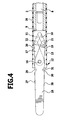
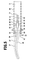
- This movement is translated into a pivoting movement of the cutting blades 17, 18 so that they are closed when the sliding block 9 is retracted ( FIGS. 4 and 5 On the other hand, with the sliding block 9 advanced, it is open ( Figures 2 and 3 ).
- the two cutting blades 17, 18 are laterally bent in the longitudinal direction, in such a way that during the movement of the cutting blades 17, 18 from the open position to the closed position, the contact area between the two cutting blades 17, 18 is displaced in the distal direction.
- the two cutting blades 17, 18 lie against the opposite, flat inner sides of the bearing arms 13, 14 and are thereby pressed against each other. Due to the shape of the cutting blades 17 and 18, the force increases at, with the cutting blades 17, 18 are pressed against each other when closing, and this causes the two bearing arms 13, 14 are bent elastically outwards, ie, the bearing gap 15 is widened.
- the outer surfaces 23, 24 of the bearing arms 13, 14 are conical, ie they lie in undeformed bearing arms on a conical surface, wherein the diameter decreases from the proximal to the distal end. This results in an unenclosed bearing arms between the Au ⁇ endon 23 and 24 and one of the outer surface of the shaft 2 corresponding cylindrical surface an annular gap 25 with increasing width in the distal direction ( FIG. 3 ).
- a cylindrical sleeve 26 is pushed, which extends in the distal direction to over the free ends of the bearing arms 13, 14 out and this covers completely laterally. This cylindrical sleeve 26 is not reached even with elastically outwardly bent bearing arms 13, 14 of these and not expanded outward.
- the cutting blades 17, 18 carry at their outer edges 27, 28 in one of the bearing shaft 16 near section each have a notch 29 and 30, which are arranged so that upon pivoting of the cutting blades 17, 18 in the open position ( FIG. 2 ) the distal edge 31 of the sleeve 26 dips into these notches 29, 30, so that the cutting blades 17, 18 in the open position can take a large angle relative to the longitudinal axis of the shaft 2, without thereby abut the distal edge 31 of the sleeve 26 and this dilate.
- the described measures are used individually and also together to avoid unwanted widening of the sleeve 26.
Landscapes
- Health & Medical Sciences (AREA)
- Surgery (AREA)
- Life Sciences & Earth Sciences (AREA)
- Biomedical Technology (AREA)
- Nuclear Medicine, Radiotherapy & Molecular Imaging (AREA)
- Engineering & Computer Science (AREA)
- Ophthalmology & Optometry (AREA)
- Heart & Thoracic Surgery (AREA)
- Medical Informatics (AREA)
- Molecular Biology (AREA)
- Animal Behavior & Ethology (AREA)
- General Health & Medical Sciences (AREA)
- Public Health (AREA)
- Veterinary Medicine (AREA)
- Surgical Instruments (AREA)
Abstract
Description
- Die Erfindung betrifft ein chirurgisches Rohrschaftinstrument mit einem länglichen Rohrschaft und mit zwei am distalen Ende des Rohrschafts im Abstand nebeneinander angeordneten und elastisch auseinander biegbaren Lagerarmen, zwischen denen mindestens ein um eine quer zur Längsachse des Rohrschaftes verlaufende Drehachse verschwenkbares Werkzeug gelagert ist, und mit einer den Rohrschaft und die Lagerarme übergreifenden rohrförmigen Hülse.
- Chirurgische Rohrschaftinstrumente dieser Art werden insbesondere bei minimalinvasiven Operationen eingesetzt, bei denen diese Instrumente durch rohrförmige Trokare in das Körperinnere eingeführt werden. Dazu ist es notwendig, dass der Außendurchmesser klein ist, trotzdem müssen die Instrumente stabil genug sein, um relativ große Kräfte zu übertragen.
- Bei bekannten Rohrschaftinstrumenten dieser Art werden die Werkzeuge, beispielsweise Klemmbacken oder Schneidklingen, im Spalt zwischen den nebeneinander angeordneten Lagerarmen verschwenkbar gelagert, dazu wird der Spalt zwischen den Lagerarmen von einer Lagerwelle durchsetzt, auf der das Werkzeug oder die Werkzeuge gelagert sind. Die Werkzeuge können durch einen geeigneten Mechanismus, der von der proximalen Seite des Rohrschaftinstrumentes aus zu bedienen ist, um die Lagerwelle verschwenkt werden, und bei dieser Verschwenkbewegung können Kräfte von den Werkzeugen auf die Lagerarme ausgeübt werden, die in Richtung der Lagerwelle verlaufen und dabei die Lagerarme auseinander biegen, d.h. der Spalt zwischen den Lagerarmen wird dadurch aufgespreizt. Dies kann beispielsweise dann der Fall sein, wenn die Werkzeuge als Schneidklingen ausgebildet und so gegeneinander gebogen oder geschränkt sind, dass sie während des gesamten Schneidvorganges mit den Schneidkanten kräftig gegeneinander gedrückt werden. Dies führt zu einer elastischen Aufbiegung der Schneidklingen und/oder der Lagerarme.
- An sich ist eine solche geringfügige Aufbiegung der Lagerarme unschädlich, es ergeben sich aber dann Schwierigkeiten, wenn das Rohrschaftinstrument von einer rohrförmigen Hülse überfangen ist, beispielsweise in Form eines dünnen Kunststoffschlauches zur Isolation und zur Verhinderung von Verletzungen. Diese Hülse überfängt üblicherweise die Lagerarme und wird beim elastischen Aufspreizen der Lagerarme gedehnt, so dass sie trichterförmig verformt wird. Dies kann das Einführen in den Trokar behindern und sollte daher vermieden werden.
- Es ist Aufgabe der Erfindung, ein chirurgisches Rohrschaftinstrument der gattungsgemäßen Art so auszubilden, dass ein unbeabsichtigtes Aufweiten der rohrförmigen Hülse auf dem Rohrschaftinstrument vermieden wird.
- Diese Aufgabe wird bei einem chirurgischen Rohrschaftinstrument der eingangs beschriebenen Art erfindungsgemäß dadurch gelöst, dass der Abstand der Außenflächen der unverbogenen Lagerarme vom Rohrschaft zu den freien Enden der Lagerarme hin abnimmt.
- Bei einer solchen Ausgestaltung ergibt sich zwischen den Außenflächen der unverbogenen Lagerarme und der Innenfläche der rohrförmigen Hülse ein Spalt, der vom Rohrschaft zum freien Ende der Lagerarme hin größer wird. Wenn die Lagerarme in der erörterten Weise bei der Verschwenkung der Werkzeuge elastisch nach außen gebogen werden, kann die Außenfläche diesen zum freien Ende hin größer werdenden Spalt verkleinern, ohne bei dieser Verbiegung an der Innenwand der rohrförmigen Hülse anzuliegen, d.h. eine Verformung der rohrförmigen Hülse unterbleibt.
- Beispielsweise kann bei einem Rohrschaftinstrument mit einem kreiszylindrischen Querschnitt vorgesehen sein, dass die Außenflächen der unverbogenen Lagerarme im Wesentlichen kegelmantelförmig ausgebildet sind, damit ergibt sich eine konische Ausgestaltung der Lagerarme am distalen Ende des Schaftes.
- Die Lagerarme können Teil des Rohrschaftes selbst sein, es ist aber bei einer abgewandelten Ausführungsform auch möglich, dass die Lagerarme Teil eines Lagerelementes sind, welches in den Rohrschaft eingesetzt ist. Dabei geht dieses Lagerelement an seiner Außenseite vorzugsweise stufenlos in den Rohrschaft über.
- Die rohrförmige Hülse kann aus Metall oder Kunststoff bestehen, günstig ist es, wenn es sich dabei um einen Kunststoffschlauch handelt, insbesondere um einen Schrumpfschlauch.
- Bei einer weiteren bevorzugten Ausführungsform ist zusätzlich vorgesehen, dass das Werkzeug oder gegebenenfalls die Werkzeuge an ihrer außen liegenden Kante eine Einkerbung aufweisen, in die bei schräg zur Längsachse des Rohrschaftes stehendem Werkzeug der distale Rand der rohrförmigen Hülse eintaucht. Auf diese Weise ist auch bei einem großen Öffnungswinkel sichergestellt, dass das geöffnete Werkzeug nicht am distalen Rand der rohrförmigen Hülse anschlägt und diese unbeabsichtigt aufweitet. Auch diese Maßnahme trägt also dazu bei, die unerwünschte Aufweitung der rohrförmigen Hülse zu vermeiden. Es kann auch vorgesehen sein, dass die Öffnungsbewegung der Werkzeuge begrenzt wird, beispielsweise durch geeignete Anschläge. Dadurch ist sichergestellt, dass die geöffneten Werkzeuge nicht am distalen Rand der rohrförmigen Hülse anschlagen und diese unbeabsichtigt aufweiten.
- Besonders vorteilhaft ist die beschriebene Ausgestaltung bei einem Instrument, bei dem zwei als Schneidklingen ausgebildete Werkzeuge vorgesehen sind, die durch die Lagerarme in Richtung der Drehachse gegeneinander gedrückt werden. Die Lagerarme wirken somit als federndes Andruckelement, dadurch werden die Schneidklingen im Kontaktbereich gegeneinander gedrückt.
- Insbesondere kann dabei vorgesehen sein, dass die Schneidklingen so gegeneinander gebogen sind, dass die Schneidklingen beim Schließen im Bereich ihrer Lagerung an den Lagerarmen mit einer ansteigenden Kraft auseinandergedrückt werden. Trotz dieser von den Lagerarmen aufzubringenden Kräfte und der daraus resultierenden Aufspreizung des Spaltes zwischen den Lagerarmen ist durch den abnehmenden Abstand der Außenflächen der Lagerarme sichergestellt, dass die Lagerarme die rohrförmige Hülse nicht aufweiten, sondern auch bei der Verbiegung mit ihrer Außenkontur immer innerhalb des Innenquerschnittes der rohrförmigen, unverformten Hülse verbleiben.
- Die nachfolgende Beschreibung bevorzugter Ausführungsformen der Erfindung dient im Zusammenhang mit der Zeichnung der näheren Erläuterung. Es zeigen:
- Figur 1:
- eine perspektivische Ansicht eines Rohrschaftinstrumentes;
- Figur 2:
- eine vergrößerte Längsschnittansicht des Bereiches A in
Figur 1 mit den Werkzeugen in einer Öffnungsstellung; - Figur 2a:
- eine vergrößerte Detailansicht des Bereiches C in
Figur 2 ; - Figur 3:
- eine Draufsicht auf den distalen Bereich des Rohrschaftinstrumentes in Richtung des Pfeiles B in
Figur 2 ; - Figur 4:
- eine Ansicht ähnlich
Figur 2 mit den Werkzeugen in Schließstellung und - Figur 5:
- eine Ansicht ähnlich
Figur 3 mit den Werkzeugen in Schließstellung. - Das in der Zeichnung dargestellte Rohrschaftinstrument 1 umfasst einen länglichen, rohrförmigen Schaft 2, an dessen proximalem Ende 3 eine etwa quer von der Längsrichtung des Rohrschaftinstrumentes 1 abstehende Branche 4 mit einer Fingeröffnung 5 angesetzt ist. Eine zweite Branche 6 mit einer Fingeröffnung 7 ist um eine quer zur Längsachse des Rohrschaftinstrumentes 1 verlaufende Schwenkachse verschwenkbar mit der feststehenden Branche 4 verbunden, so dass die beiden Branchen 4, 6 gegeneinander und wieder auseinander geschwenkt werden können.
- Im Inneren des Schaftes 2 ist eine in Längsrichtung des Schaftes 2 frei verschiebbare Schub- und Zugstange 8 gelagert, die am proximalen Ende gelenkig mit der verschwenkbaren Branche 6 verbunden ist, so dass bei deren Verschwenkbewegung die Schub- und Zugstange 8 im Schaft 2 vor- bzw. zurückgeschoben wird.
- Am distalen Ende trägt die Schub- und Zugstange 8 einen Gleitstein 9 mit gebogenen, rinnenförmigen Vertiefungen 10, 11 auf gegenüberliegenden Seiten.
- Am distalen Ende 12 trägt der Schaft 2 zwei in Längsrichtung des Schaftes parallel und mit Abstand zueinander verlaufende Lagerarme 13, 14, die zwischen sich einen Lagerspalt 15 ausbilden. Dieser wird von einer an den beiden Lagerarmen 13, 14 gehaltenen, quer zur Längsrichtung des Schaftes 2 verlaufenden Lagerwelle 16 überbrückt, die im vorderen Bereich der Lagerarme 13, 14 nahe dem freien Ende der Lagerarme 13, 14 angeordnet ist.
- Auf der Lagerwelle 16 sind zwei Schneidklingen 17, 18 um die durch die Lagerwelle 16 gebildete Drehachse verschwenkbar gelagert. Eine Verschwenkung erfolgt durch eine Längsverschiebung des Gleitsteines 9, der sich am proximalen Ende des Lagerspaltes 15 in diesem befindet und an dessen Seitenwänden die rückwärtigen Enden 19, 20 der Schneidklingen 17, 18 anliegen. In diesem Anlagebereich tragen die rückwärtigen Enden 19, 20 seitlich vorstehende Zapfen 21, 22, die in die rinnenförmigen Vertiefungen 10 bzw. 11 des Gleitsteines 9 eintauchen und bei Längsverschiebung des Gleitsteines 9 durch die Seitenwände dieser rinnenförmigen Vertiefungen 10, 11 geführt werden. Diese Bewegung wird in eine Verschwenkbewegung der Schneidklingen 17, 18 übersetzt, so dass diese bei zurückgezogenem Gleitstein 9 geschlossen sind (
Figuren 4 und5 ), bei vorgeschobenem Gleitstein 9 dagegen geöffnet (Figuren 2 und3 ). - Die beiden Schneidklingen 17, 18 sind in Längsrichtung seitlich abgebogen, und zwar derart, dass bei der Bewegung der Schneidklingen 17, 18 von der Öffnungsstellung in die Schließstellung der Kontaktbereich zwischen den beiden Schneidklingen 17, 18 in distaler Richtung verschoben wird. Die beiden Schneidklingen 17, 18 liegen dabei an den einander gegenüberliegenden, ebenen Innenseiten der Lagerarme 13, 14 an und werden dadurch gegeneinander gedrückt. Durch die Formgebung der Schneidklingen 17 und 18 steigt die Kraft an, mit der die Schneidklingen 17, 18 beim Schließen gegeneinander gedrückt werden, und dies führt dazu, dass die beiden Lagerarme 13, 14 elastisch nach außen gebogen werden, d.h. der Lagerspalt 15 wird aufgeweitet.
- Aus diesem Grund sind die Außenflächen 23, 24 der Lagerarme 13, 14 konisch ausgebildet, d.h. sie liegen bei unverformten Lagerarmen auf einem Kegelmantel, wobei der Durchmesser vom proximalen zum distalen Ende hin abnimmt. Es entsteht dadurch bei unverbogenen Lagerarmen zwischen den Au-βenflächen 23 und 24 und einer der Außenfläche des Schaftes 2 entsprechenden Zylinderfläche ein Ringspalt 25 mit in distaler Richtung zunehmender Breite (
Figur 3 ). - Beim elastischen Aufbiegen der Lagerarme 13, 14 in Längsrichtung der Lagerwelle 16 können die Außenflächen 23 und 24 in diesen Ringspalt 25 eintreten und verbleiben dabei trotzdem immer noch innerhalb des Querschnittes der durch die Außenseite des Schaftes 2 definierten Zylinderfläche. Es ist damit sichergestellt, dass die Außenflächen 23 und 24 bei der Schließbewegung der Schneidklingen 17, 18 nicht nach außen über diese Zylinderfläche hervortreten.
- Auf den Schaft 2 ist eine zylinderförmige Hülse 26 aufgeschoben, die sich in distaler Richtung bis über die freien Enden der Lagerarme 13, 14 hin erstreckt und diese vollständig seitlich abdeckt. Diese zylinderförmige Hülse 26 wird auch bei elastisch nach außen gebogenen Lagerarmen 13, 14 von diesen nicht erreicht und nicht nach außen ausgeweitet.
- Die Schneidklingen 17, 18 tragen an ihren Außenkanten 27, 28 in einem der Lagerwelle 16 naheliegenden Abschnitt jeweils eine Einkerbung 29 bzw. 30, die so angeordnet sind, dass beim Verschwenken der Schneidklingen 17, 18 in die Öffnungsstellung (
Figur 2 ) der distale Rand 31 der Hülse 26 in diese Einkerbungen 29, 30 eintaucht, so dass die Schneidklingen 17, 18 in der Öffnungsstellung einen großen Winkel gegenüber der Längsachse des Schaftes 2 einnehmen können, ohne dadurch am distalen Rand 31 der Hülse 26 anzustoßen und diese aufzuweiten. - Die geschilderten Maßnahmen dienen jeweils für sich und auch gemeinsam dazu, eine unerwünschte Aufweitung der Hülse 26 zu vermeiden.
Claims (7)
- Chirurgisches Rohrschaftinstrument (1) mit einem länglichen Rohrschaft (2) und mit zwei am distalen Ende (12) des Rohrschafts (2) im Abstand nebeneinander angeordneten und elastisch auseinander biegbaren Lagerarmen (13, 14), zwischen denen mindestens ein um eine quer zur Längsachse des Rohrschaftes (2) verlaufende Drehachse verschwenkbares Werkzeug gelagert ist, und mit einer den Rohrschaft (2) und die Lagerarme (13, 14) übergreifenden rohrförmigen Hülse (26), dadurch gekennzeichnet, dass der Abstand der Außenflächen (23, 24) der unverbogenen Lagerarme (13, 14) vom Rohrschaft (2) zu den freien Enden der Lagerarme (13, 14) hin abnimmt.
- Rohrschaftinstrument nach Anspruch 1, dadurch gekennzeichnet, dass die Außenflächen (23, 24) der unverbogenen Lagerarme (13, 14) im wesentlichen kegelmantelförmig ausgebildet sind.
- Rohrschaftinstrument nach einem der Ansprüche 1 oder 2, dadurch gekennzeichnet, dass die Lagerarme (13, 14) Teil eines Lagerelements sind, welches in den Rohrschaft (2) eingesetzt ist.
- Rohrschaftinstrument nach einem der voranstehenden Ansprüche, dadurch gekennzeichnet, dass die rohrförmige Hülse (26) ein Kunststoffschlauch ist.
- Rohrschaftinstrument nach einem der voranstehenden Ansprüche, dadurch gekennzeichnet, dass das Werkzeug oder gegebenenfalls die Werkzeuge (17, 18) an ihrer außen liegenden Kante (27, 28) eine Einkerbung (29, 30) aufweisen, in die bei schräg zur Längsachse des Rohrschaftes (2) stehendem Werkzeug (17, 18) der distale Rand (31) der rohrförmigen Hülse (26) eintaucht.
- Rohrschaftinstrument nach einem der voranstehenden Ansprüche, dadurch gekennzeichnet, dass zwei als Schneidklingen ausgebildete Werkzeuge (17, 18) vorgesehen sind, die durch die Lagerarme (13, 14) in Richtung der Drehachse gegeneinander gedrückt werden.
- Rohrschaftinstrument nach Anspruch 6, dadurch gekennzeichnet, dass die Werkzeuge (17, 18) so gegeneinander gebogen sind, dass sie beim Schließen im Bereich ihrer Lagerung an den Lagerarmen (13, 14) mit einer ansteigenden Kraft auseinandergedrückt werden.
Applications Claiming Priority (1)
| Application Number | Priority Date | Filing Date | Title |
|---|---|---|---|
| DE102007002250A DE102007002250B3 (de) | 2007-01-11 | 2007-01-11 | Chirurgisches Rohrschaftinstrument |
Publications (2)
| Publication Number | Publication Date |
|---|---|
| EP1943968A1 true EP1943968A1 (de) | 2008-07-16 |
| EP1943968B1 EP1943968B1 (de) | 2011-10-05 |
Family
ID=39245595
Family Applications (1)
| Application Number | Title | Priority Date | Filing Date |
|---|---|---|---|
| EP07121962A Active EP1943968B1 (de) | 2007-01-11 | 2007-11-30 | Chirurgisches Rohrschaftinstrument |
Country Status (4)
| Country | Link |
|---|---|
| EP (1) | EP1943968B1 (de) |
| AT (1) | ATE526889T1 (de) |
| DE (1) | DE102007002250B3 (de) |
| ES (1) | ES2371672T3 (de) |
Cited By (1)
| Publication number | Priority date | Publication date | Assignee | Title |
|---|---|---|---|---|
| US10660626B2 (en) | 2007-10-05 | 2020-05-26 | Covidien Lp | Hand-held surgical devices |
Citations (4)
| Publication number | Priority date | Publication date | Assignee | Title |
|---|---|---|---|---|
| WO1993012722A1 (en) * | 1991-12-27 | 1993-07-08 | Symbiosis Corporation | Hermaprhoditic endoscopic claw extractors |
| US5695521A (en) * | 1996-10-01 | 1997-12-09 | Symbiosis Corporation | Tubular sheath protective insert |
| EP1177771A1 (de) * | 1994-07-29 | 2002-02-06 | Olympus Optical Co., Ltd. | Medizinisches Instrument zur Benutzung in Kombination mit Endoskopen |
| US20060184198A1 (en) * | 2005-01-31 | 2006-08-17 | Kms Biopsy, Llc | End effector for surgical instrument, surgical instrument, and method for forming the end effector |
Family Cites Families (2)
| Publication number | Priority date | Publication date | Assignee | Title |
|---|---|---|---|---|
| US6086606A (en) * | 1998-05-06 | 2000-07-11 | Knodel; Bryan D. | Manually-operable surgical tool suitable for laparoscopic operations, readily adaptable for different functions by quick change of tissue-contacting operational elements |
| DE20309778U1 (de) * | 2003-06-20 | 2003-08-28 | Aesculap AG & Co. KG, 78532 Tuttlingen | Chirurgisches Instrument |
-
2007
- 2007-01-11 DE DE102007002250A patent/DE102007002250B3/de active Active
- 2007-11-30 EP EP07121962A patent/EP1943968B1/de active Active
- 2007-11-30 AT AT07121962T patent/ATE526889T1/de active
- 2007-11-30 ES ES07121962T patent/ES2371672T3/es active Active
Patent Citations (4)
| Publication number | Priority date | Publication date | Assignee | Title |
|---|---|---|---|---|
| WO1993012722A1 (en) * | 1991-12-27 | 1993-07-08 | Symbiosis Corporation | Hermaprhoditic endoscopic claw extractors |
| EP1177771A1 (de) * | 1994-07-29 | 2002-02-06 | Olympus Optical Co., Ltd. | Medizinisches Instrument zur Benutzung in Kombination mit Endoskopen |
| US5695521A (en) * | 1996-10-01 | 1997-12-09 | Symbiosis Corporation | Tubular sheath protective insert |
| US20060184198A1 (en) * | 2005-01-31 | 2006-08-17 | Kms Biopsy, Llc | End effector for surgical instrument, surgical instrument, and method for forming the end effector |
Cited By (2)
| Publication number | Priority date | Publication date | Assignee | Title |
|---|---|---|---|---|
| US10660626B2 (en) | 2007-10-05 | 2020-05-26 | Covidien Lp | Hand-held surgical devices |
| US11389144B2 (en) | 2010-04-16 | 2022-07-19 | Covidien Lp | Hand-held surgical devices |
Also Published As
| Publication number | Publication date |
|---|---|
| EP1943968B1 (de) | 2011-10-05 |
| DE102007002250B3 (de) | 2008-05-21 |
| ATE526889T1 (de) | 2011-10-15 |
| ES2371672T3 (es) | 2012-01-09 |
Similar Documents
| Publication | Publication Date | Title |
|---|---|---|
| DE10328514B3 (de) | Chirurgisches Instrument | |
| DE69835148T2 (de) | Chirurgische clips und klemmen | |
| EP0699054B1 (de) | Chirurgisches instrument mit zwei trennbaren griffbranchen | |
| EP1065979B1 (de) | Chirurgisches instrument mit einem durchgehenden hohlkanal für ein weiteres instrument | |
| EP2213254B1 (de) | Chirurgisches Instrument | |
| DE69731096T2 (de) | Pinzette, insbesondere zur biopsie | |
| EP2249715B1 (de) | Zerlegbares chirurgisches instrument | |
| EP1052945B1 (de) | Medizinisches rohrschaftinstrument | |
| WO2011018154A1 (de) | Elektrochirurgisches instrument | |
| CH685368A5 (de) | Medizinisches Instrument. | |
| EP0732894B1 (de) | Instrument für chirurgische zwecke | |
| DE102009056099B4 (de) | Chirurgisches Instrument | |
| EP1279371A1 (de) | Chirurgisches Instrument | |
| DE102004030030A1 (de) | Griffteil für ein chirurgisches Instrument | |
| EP1943968B1 (de) | Chirurgisches Rohrschaftinstrument | |
| EP2653122B1 (de) | Werkzeug für ein medizinisches Instrument | |
| DE202007000624U1 (de) | Chirurgisches Rohrschaftinstrument | |
| DE102007030874B4 (de) | Chirurgisches Instrument | |
| DE3716764A1 (de) | Medizinisches, insbesondere chirurgisches instrument mit einem saugrohr | |
| DE10353006B4 (de) | Chirurgisches Rohrschaftinstrument | |
| DE102007054432B3 (de) | Chirurgisches Instrument | |
| DE202007009315U1 (de) | Chirurgisches Instrument | |
| DE202007000427U1 (de) | Chirurgischer Haltegriff und chirurgisches Instrument | |
| DE10163863B4 (de) | Chirurgisches Instrument mit einem Werkzeughalter | |
| EP2591735B1 (de) | Verlängerung für Knochenhebel oder Wundhaken |
Legal Events
| Date | Code | Title | Description |
|---|---|---|---|
| PUAI | Public reference made under article 153(3) epc to a published international application that has entered the european phase |
Free format text: ORIGINAL CODE: 0009012 |
|
| AK | Designated contracting states |
Kind code of ref document: A1 Designated state(s): AT BE BG CH CY CZ DE DK EE ES FI FR GB GR HU IE IS IT LI LT LU LV MC MT NL PL PT RO SE SI SK TR |
|
| AX | Request for extension of the european patent |
Extension state: AL BA HR MK RS |
|
| RAP1 | Party data changed (applicant data changed or rights of an application transferred) |
Owner name: AESCULAP AG |
|
| 17P | Request for examination filed |
Effective date: 20090110 |
|
| AKX | Designation fees paid |
Designated state(s): AT BE BG CH CY CZ DE DK EE ES FI FR GB GR HU IE IS IT LI LT LU LV MC MT NL PL PT RO SE SI SK TR |
|
| 17Q | First examination report despatched |
Effective date: 20090717 |
|
| GRAP | Despatch of communication of intention to grant a patent |
Free format text: ORIGINAL CODE: EPIDOSNIGR1 |
|
| GRAS | Grant fee paid |
Free format text: ORIGINAL CODE: EPIDOSNIGR3 |
|
| RBV | Designated contracting states (corrected) |
Designated state(s): AT BE BG CH CY CZ DK EE ES FI FR GB GR HU IE IS IT LI LT LU LV MC MT NL PL PT RO SE SI SK TR |
|
| REG | Reference to a national code |
Ref country code: DE Ref legal event code: R108 |
|
| GRAA | (expected) grant |
Free format text: ORIGINAL CODE: 0009210 |
|
| AK | Designated contracting states |
Kind code of ref document: B1 Designated state(s): AT BE BG CH CY CZ DK EE ES FI FR GB GR HU IE IS IT LI LT LU LV MC MT NL PL PT RO SE SI SK TR |
|
| REG | Reference to a national code |
Ref country code: GB Ref legal event code: FG4D Free format text: NOT ENGLISH |
|
| REG | Reference to a national code |
Ref country code: DE Ref legal event code: R108 Effective date: 20110822 |
|
| REG | Reference to a national code |
Ref country code: CH Ref legal event code: EP |
|
| REG | Reference to a national code |
Ref country code: IE Ref legal event code: FG4D |
|
| REG | Reference to a national code |
Ref country code: ES Ref legal event code: FG2A Ref document number: 2371672 Country of ref document: ES Kind code of ref document: T3 Effective date: 20120109 |
|
| REG | Reference to a national code |
Ref country code: NL Ref legal event code: VDEP Effective date: 20111005 |
|
| PG25 | Lapsed in a contracting state [announced via postgrant information from national office to epo] |
Ref country code: SI Free format text: LAPSE BECAUSE OF FAILURE TO SUBMIT A TRANSLATION OF THE DESCRIPTION OR TO PAY THE FEE WITHIN THE PRESCRIBED TIME-LIMIT Effective date: 20111005 |
|
| LTIE | Lt: invalidation of european patent or patent extension |
Effective date: 20111005 |
|
| PG25 | Lapsed in a contracting state [announced via postgrant information from national office to epo] |
Ref country code: IS Free format text: LAPSE BECAUSE OF FAILURE TO SUBMIT A TRANSLATION OF THE DESCRIPTION OR TO PAY THE FEE WITHIN THE PRESCRIBED TIME-LIMIT Effective date: 20120205 Ref country code: LT Free format text: LAPSE BECAUSE OF FAILURE TO SUBMIT A TRANSLATION OF THE DESCRIPTION OR TO PAY THE FEE WITHIN THE PRESCRIBED TIME-LIMIT Effective date: 20111005 |
|
| REG | Reference to a national code |
Ref country code: IE Ref legal event code: FD4D |
|
| BERE | Be: lapsed |
Owner name: AESCULAP A.G. Effective date: 20111130 |
|
| PG25 | Lapsed in a contracting state [announced via postgrant information from national office to epo] |
Ref country code: SE Free format text: LAPSE BECAUSE OF FAILURE TO SUBMIT A TRANSLATION OF THE DESCRIPTION OR TO PAY THE FEE WITHIN THE PRESCRIBED TIME-LIMIT Effective date: 20111005 Ref country code: GR Free format text: LAPSE BECAUSE OF FAILURE TO SUBMIT A TRANSLATION OF THE DESCRIPTION OR TO PAY THE FEE WITHIN THE PRESCRIBED TIME-LIMIT Effective date: 20120106 Ref country code: NL Free format text: LAPSE BECAUSE OF FAILURE TO SUBMIT A TRANSLATION OF THE DESCRIPTION OR TO PAY THE FEE WITHIN THE PRESCRIBED TIME-LIMIT Effective date: 20111005 Ref country code: LV Free format text: LAPSE BECAUSE OF FAILURE TO SUBMIT A TRANSLATION OF THE DESCRIPTION OR TO PAY THE FEE WITHIN THE PRESCRIBED TIME-LIMIT Effective date: 20111005 Ref country code: PT Free format text: LAPSE BECAUSE OF FAILURE TO SUBMIT A TRANSLATION OF THE DESCRIPTION OR TO PAY THE FEE WITHIN THE PRESCRIBED TIME-LIMIT Effective date: 20120206 |
|
| PG25 | Lapsed in a contracting state [announced via postgrant information from national office to epo] |
Ref country code: CY Free format text: LAPSE BECAUSE OF FAILURE TO SUBMIT A TRANSLATION OF THE DESCRIPTION OR TO PAY THE FEE WITHIN THE PRESCRIBED TIME-LIMIT Effective date: 20111005 Ref country code: MC Free format text: LAPSE BECAUSE OF NON-PAYMENT OF DUE FEES Effective date: 20111130 |
|
| REG | Reference to a national code |
Ref country code: CH Ref legal event code: PL |
|
| PG25 | Lapsed in a contracting state [announced via postgrant information from national office to epo] |
Ref country code: SK Free format text: LAPSE BECAUSE OF FAILURE TO SUBMIT A TRANSLATION OF THE DESCRIPTION OR TO PAY THE FEE WITHIN THE PRESCRIBED TIME-LIMIT Effective date: 20111005 Ref country code: EE Free format text: LAPSE BECAUSE OF FAILURE TO SUBMIT A TRANSLATION OF THE DESCRIPTION OR TO PAY THE FEE WITHIN THE PRESCRIBED TIME-LIMIT Effective date: 20111005 Ref country code: DK Free format text: LAPSE BECAUSE OF FAILURE TO SUBMIT A TRANSLATION OF THE DESCRIPTION OR TO PAY THE FEE WITHIN THE PRESCRIBED TIME-LIMIT Effective date: 20111005 Ref country code: CZ Free format text: LAPSE BECAUSE OF FAILURE TO SUBMIT A TRANSLATION OF THE DESCRIPTION OR TO PAY THE FEE WITHIN THE PRESCRIBED TIME-LIMIT Effective date: 20111005 Ref country code: IE Free format text: LAPSE BECAUSE OF FAILURE TO SUBMIT A TRANSLATION OF THE DESCRIPTION OR TO PAY THE FEE WITHIN THE PRESCRIBED TIME-LIMIT Effective date: 20111005 Ref country code: BG Free format text: LAPSE BECAUSE OF FAILURE TO SUBMIT A TRANSLATION OF THE DESCRIPTION OR TO PAY THE FEE WITHIN THE PRESCRIBED TIME-LIMIT Effective date: 20120105 Ref country code: CH Free format text: LAPSE BECAUSE OF NON-PAYMENT OF DUE FEES Effective date: 20111130 Ref country code: LI Free format text: LAPSE BECAUSE OF NON-PAYMENT OF DUE FEES Effective date: 20111130 |
|
| PLBE | No opposition filed within time limit |
Free format text: ORIGINAL CODE: 0009261 |
|
| STAA | Information on the status of an ep patent application or granted ep patent |
Free format text: STATUS: NO OPPOSITION FILED WITHIN TIME LIMIT |
|
| PG25 | Lapsed in a contracting state [announced via postgrant information from national office to epo] |
Ref country code: PL Free format text: LAPSE BECAUSE OF FAILURE TO SUBMIT A TRANSLATION OF THE DESCRIPTION OR TO PAY THE FEE WITHIN THE PRESCRIBED TIME-LIMIT Effective date: 20111005 Ref country code: BE Free format text: LAPSE BECAUSE OF NON-PAYMENT OF DUE FEES Effective date: 20111130 Ref country code: RO Free format text: LAPSE BECAUSE OF FAILURE TO SUBMIT A TRANSLATION OF THE DESCRIPTION OR TO PAY THE FEE WITHIN THE PRESCRIBED TIME-LIMIT Effective date: 20111005 |
|
| 26N | No opposition filed |
Effective date: 20120706 |
|
| PG25 | Lapsed in a contracting state [announced via postgrant information from national office to epo] |
Ref country code: MT Free format text: LAPSE BECAUSE OF FAILURE TO SUBMIT A TRANSLATION OF THE DESCRIPTION OR TO PAY THE FEE WITHIN THE PRESCRIBED TIME-LIMIT Effective date: 20111005 |
|
| PG25 | Lapsed in a contracting state [announced via postgrant information from national office to epo] |
Ref country code: LU Free format text: LAPSE BECAUSE OF NON-PAYMENT OF DUE FEES Effective date: 20111130 |
|
| PG25 | Lapsed in a contracting state [announced via postgrant information from national office to epo] |
Ref country code: FI Free format text: LAPSE BECAUSE OF FAILURE TO SUBMIT A TRANSLATION OF THE DESCRIPTION OR TO PAY THE FEE WITHIN THE PRESCRIBED TIME-LIMIT Effective date: 20111005 |
|
| PG25 | Lapsed in a contracting state [announced via postgrant information from national office to epo] |
Ref country code: TR Free format text: LAPSE BECAUSE OF FAILURE TO SUBMIT A TRANSLATION OF THE DESCRIPTION OR TO PAY THE FEE WITHIN THE PRESCRIBED TIME-LIMIT Effective date: 20111005 |
|
| PG25 | Lapsed in a contracting state [announced via postgrant information from national office to epo] |
Ref country code: HU Free format text: LAPSE BECAUSE OF FAILURE TO SUBMIT A TRANSLATION OF THE DESCRIPTION OR TO PAY THE FEE WITHIN THE PRESCRIBED TIME-LIMIT Effective date: 20111005 |
|
| REG | Reference to a national code |
Ref country code: AT Ref legal event code: MM01 Ref document number: 526889 Country of ref document: AT Kind code of ref document: T Effective date: 20121130 |
|
| PG25 | Lapsed in a contracting state [announced via postgrant information from national office to epo] |
Ref country code: AT Free format text: LAPSE BECAUSE OF NON-PAYMENT OF DUE FEES Effective date: 20121130 |
|
| REG | Reference to a national code |
Ref country code: FR Ref legal event code: PLFP Year of fee payment: 9 |
|
| REG | Reference to a national code |
Ref country code: FR Ref legal event code: PLFP Year of fee payment: 10 |
|
| REG | Reference to a national code |
Ref country code: FR Ref legal event code: PLFP Year of fee payment: 11 |
|
| P01 | Opt-out of the competence of the unified patent court (upc) registered |
Effective date: 20230922 |
|
| PGFP | Annual fee paid to national office [announced via postgrant information from national office to epo] |
Ref country code: GB Payment date: 20251120 Year of fee payment: 19 |
|
| PGFP | Annual fee paid to national office [announced via postgrant information from national office to epo] |
Ref country code: IT Payment date: 20251128 Year of fee payment: 19 |
|
| PGFP | Annual fee paid to national office [announced via postgrant information from national office to epo] |
Ref country code: FR Payment date: 20251125 Year of fee payment: 19 |
|
| PGFP | Annual fee paid to national office [announced via postgrant information from national office to epo] |
Ref country code: ES Payment date: 20251216 Year of fee payment: 19 |