EP1943878B1 - Plaque de cuisson et procede permettant de faire fonctionner une plaque de cuisson - Google Patents
Plaque de cuisson et procede permettant de faire fonctionner une plaque de cuisson Download PDFInfo
- Publication number
- EP1943878B1 EP1943878B1 EP06807106A EP06807106A EP1943878B1 EP 1943878 B1 EP1943878 B1 EP 1943878B1 EP 06807106 A EP06807106 A EP 06807106A EP 06807106 A EP06807106 A EP 06807106A EP 1943878 B1 EP1943878 B1 EP 1943878B1
- Authority
- EP
- European Patent Office
- Prior art keywords
- heating
- switching
- heating zone
- cooking hob
- operating mode
- Prior art date
- Legal status (The legal status is an assumption and is not a legal conclusion. Google has not performed a legal analysis and makes no representation as to the accuracy of the status listed.)
- Active
Links
- 238000010411 cooking Methods 0.000 title claims abstract description 24
- 238000000034 method Methods 0.000 title claims description 4
- 238000010438 heat treatment Methods 0.000 claims abstract description 130
- 230000006698 induction Effects 0.000 claims abstract description 20
- 238000006243 chemical reaction Methods 0.000 claims description 7
- 230000004913 activation Effects 0.000 claims description 2
- 230000008878 coupling Effects 0.000 claims 1
- 238000010168 coupling process Methods 0.000 claims 1
- 238000005859 coupling reaction Methods 0.000 claims 1
- 230000003213 activating effect Effects 0.000 description 2
- 230000001419 dependent effect Effects 0.000 description 2
- 238000010586 diagram Methods 0.000 description 2
- 230000000903 blocking effect Effects 0.000 description 1
- 239000003990 capacitor Substances 0.000 description 1
- 230000000694 effects Effects 0.000 description 1
- 238000012986 modification Methods 0.000 description 1
- 230000004048 modification Effects 0.000 description 1
- 238000013021 overheating Methods 0.000 description 1
- 230000005855 radiation Effects 0.000 description 1
Images


Classifications
-
- H—ELECTRICITY
- H05—ELECTRIC TECHNIQUES NOT OTHERWISE PROVIDED FOR
- H05B—ELECTRIC HEATING; ELECTRIC LIGHT SOURCES NOT OTHERWISE PROVIDED FOR; CIRCUIT ARRANGEMENTS FOR ELECTRIC LIGHT SOURCES, IN GENERAL
- H05B6/00—Heating by electric, magnetic or electromagnetic fields
- H05B6/02—Induction heating
- H05B6/04—Sources of current
-
- H—ELECTRICITY
- H05—ELECTRIC TECHNIQUES NOT OTHERWISE PROVIDED FOR
- H05B—ELECTRIC HEATING; ELECTRIC LIGHT SOURCES NOT OTHERWISE PROVIDED FOR; CIRCUIT ARRANGEMENTS FOR ELECTRIC LIGHT SOURCES, IN GENERAL
- H05B6/00—Heating by electric, magnetic or electromagnetic fields
- H05B6/02—Induction heating
- H05B6/06—Control, e.g. of temperature, of power
- H05B6/062—Control, e.g. of temperature, of power for cooking plates or the like
- H05B6/065—Control, e.g. of temperature, of power for cooking plates or the like using coordinated control of multiple induction coils
-
- H—ELECTRICITY
- H05—ELECTRIC TECHNIQUES NOT OTHERWISE PROVIDED FOR
- H05B—ELECTRIC HEATING; ELECTRIC LIGHT SOURCES NOT OTHERWISE PROVIDED FOR; CIRCUIT ARRANGEMENTS FOR ELECTRIC LIGHT SOURCES, IN GENERAL
- H05B6/00—Heating by electric, magnetic or electromagnetic fields
- H05B6/02—Induction heating
- H05B6/10—Induction heating apparatus, other than furnaces, for specific applications
- H05B6/12—Cooking devices
- H05B6/1209—Cooking devices induction cooking plates or the like and devices to be used in combination with them
- H05B6/1245—Cooking devices induction cooking plates or the like and devices to be used in combination with them with special coil arrangements
- H05B6/1272—Cooking devices induction cooking plates or the like and devices to be used in combination with them with special coil arrangements with more than one coil or coil segment per heating zone
-
- Y—GENERAL TAGGING OF NEW TECHNOLOGICAL DEVELOPMENTS; GENERAL TAGGING OF CROSS-SECTIONAL TECHNOLOGIES SPANNING OVER SEVERAL SECTIONS OF THE IPC; TECHNICAL SUBJECTS COVERED BY FORMER USPC CROSS-REFERENCE ART COLLECTIONS [XRACs] AND DIGESTS
- Y02—TECHNOLOGIES OR APPLICATIONS FOR MITIGATION OR ADAPTATION AGAINST CLIMATE CHANGE
- Y02B—CLIMATE CHANGE MITIGATION TECHNOLOGIES RELATED TO BUILDINGS, e.g. HOUSING, HOUSE APPLIANCES OR RELATED END-USER APPLICATIONS
- Y02B40/00—Technologies aiming at improving the efficiency of home appliances, e.g. induction cooking or efficient technologies for refrigerators, freezers or dish washers
Definitions
- the invention relates to a hob according to the preamble of claim 1 and to a method for operating a hob according to the preamble of claim 12.
- An induction hob with at least one first heating zone which has two independently heatable heating elements, which are operated in a normal operating mode via a first switching device with a first power supply device.
- In the normal operating mode can be operated depending on a size of Gargut mattersers or pot, which is arranged on the heating zone, both heating elements or only one heating element of the heating zone.
- induction hobs with further heating zones for heating further food containers or pots are known from the prior art, which are operated in the normal operating mode via a second switching device with a second power supply device.
- the object of the invention is in particular to provide a generic hob with a special mode in which a heating power of the first heating zone above a maximum power of the first power supply device can be increased and in the normal operating mode, the first heating zone with both heating elements and the other heating zone simultaneously can be operated.
- the invention is based on a hob, in particular an induction hob, with at least one first heating zone having at least two independently heatable heating elements, which are operated in a normal operating mode via a first switching device with a first power supply device, and with at least one other Heating zone, which is operated in the normal operating mode via a second switching device with a second power supply device.
- the cooktop comprises a switching element for establishing a power supply connection between the second power supply device and one of the heating elements of the first heating zone, the power supply connection being produced in a special operating mode for increasing a heating power of the first heating zone.
- the second power supply device is used to supply the first heating zone only when the special operating mode is active or only when a heating power exceeding the maximum power of the first power supply device is actually requested. It can be achieved, in particular, that the second power supply device is always available for operating the further heating zone in the normal mode, even if both heating elements of the first heating zone are in operation.
- the size and shape of the heating zone can be varied by the switching on and off of heating elements.
- the idea of the invention can be used profitably mainly in the field of induction hobs because of the high-frequency technology used there, in principle also a use in connection with hobs with ohmic heating elements is conceivable.
- an intermodulation hum can be avoided when operating a plurality of heating elements with different frequencies.
- the intermodulation buzzing can be avoided particularly reliably if the hob comprises a synchronization line for synchronizing the power supply devices.
- a frequency generator of a first power supply device as a master and a frequency generator of the second power supply device can be used as a slave.
- the frequency encoders of the power supply devices can be designed to be particularly space-saving and cost-effective as application-specific integrated circuits (ASICs), which each control an inverter of the power supply device.
- ASICs application-specific integrated circuits
- the application specific integrated circuits can in turn be operated by a low-frequency switching microcontroller, which may be arranged together with the ASIC and the inverter on a common circuit board which carries the switching device.
- a low-frequency switching microcontroller which may be arranged together with the ASIC and the inverter on a common circuit board which carries the switching device.
- the two switching devices are carried by a common circuit board.
- a comfortable, short-term increase in heating power can be achieved by a switching means for manually activating the special operating mode. Overheating of the hob can be avoided if the special operating mode automatically deactivates after the expiration of a preset time.
- the special operating mode can thus be regarded as a short-term heating power boost. Further embodiments of the invention are conceivable in which the special operating mode is automatically deactivated when a temperature threshold is reached.
- An overload of the second power supply device can be avoided if the further heating zone is deactivated in the special operating mode. This can be achieved either by deactivating the second heating zone for the duration of operation in the special operating mode or by blocking the activation of the special operating mode whenever the further heating zone is active and conversely the further heating zone during operation in the special operating mode can not be switched on.
- the hob comprises a connection line for connecting the second power supply device to one of the heating elements of the first heating zone, crosstalk of the frequencies of the two power supply devices can be at least reduced by a remote arrangement thereof.
- a disturbance due to a disturbance frequency, as produced by a non-linear superimposition of the conversion frequencies of the two switching devices, can be controlled if one of the switching devices is intended to limit a difference frequency between a conversion frequency of the first switching device and a conversion frequency of the second switching device.
- An audible acoustic disturbance can be completely avoided if the switching device is intended to determine the difference frequency to lie outside an audible frequency band.
- the hob comprises a switching device for changing the connections between the power supply devices and the heating zones for switching between the normal operating mode and the special operating mode
- the power supply devices from conventional cooking hobs can be used largely without change in a hob according to the invention. A number of additional cabling can be reduced.
- Additional lines carrying a working current can be avoided when a first switch for disconnecting a first heating element of the first heating zone from the first power supply device is arranged in the first switching device.
- the invention relates to a method for operating a hob, in particular an induction hob, having at least a first heating zone having at least two independently heatable heating elements, wherein in a normal operating mode, the two heating elements are operated via a first switching device with a first power supply device and another heating zone is operated via a second switching device with a second power supply device.
- a switching element for establishing a power supply connection between the second power supply device and one of the heating elements of the first heating zone is actuated for switching on and off a special operating mode for increasing a heating power of the first heating zone.
- a generic hob can be operated in a special operating mode in which a heating power of the first heating zone can be increased above a maximum power of the first power supply device.
- both heating elements of the first heating zone and the other heating zone can be operated simultaneously in the normal operating mode.
- FIG. 1 shows an induction hob with a total of three heating zones 10, 12, 14.
- a first heating zone 10 has two independently operable heating elements 16, 18 in the form of concentric rings, which are operated in a normal operating mode via a first switching device 20 with a first power supply device 26.
- the power supply device 26 has two outputs 40, 42.
- the heating elements 16, 18 are formed as induction coils and provided to transmit electrical energy to a resonator circuit in a cooking utensil or pot, not shown here, on the Induction hob can be arranged.
- the induction hob also includes a Kochtopferkennungungssystem that detects about the load or a complex-valued impedance of the heating elements 16, 18, whether a cooking product is placed on the induction hob and what size of Gargut capableer has. If the cooking utensil container is significantly larger than the inner heating element 16, the first switching device 20 for heating the cooking utensil next to the inner heating element 16 also switches on the first, outer heating element 18, which surrounds the inner heating element 16 in an annular manner.
- the two further heating zones 12, 14 are operated in the normal operating mode via a second switching device 22 with a second power supply device 28, which also has two outputs 44, 46.
- a power supply connection between the second power supply device 28 and the outer, annular heating element 18 of the first heating zone 10 can be produced.
- the input unit 47 includes a special key that forms a switching means 34 for manually activating the special mode of operation. After the expiration of a preset time, the special operation mode ends automatically and without further operator intervention.
- the two further heating zones 12, 14 are simultaneously deactivated.
- the high-frequency AC voltage generated by the corresponding output 44 of the second power supply device 28 is given by the switching or electronic switching of the integrated into the second switching device 22 switching element 32 to a connecting line 38.
- the connection line 38 is provided for connecting the second power supply device 28 to the outer heating element 18 of the first heating zone 10.
- the connecting line 38 opens into a further switching device 24 for changing the links between the power supply devices 26, 28 and the heating zones 10, 12, 14.
- the further switching device 24 changes these links for switching between the normal operating mode and the special operating mode and also includes the first switching element 30th
- the switching of a first switching element 30 of the further switching device 24 interrupts a connection between the output 42 of the first power supply device 26 and the outer heating element 18 of the first heating zone 10 and at the same time a connection between the outer heating element 18 and the connecting line 38 or the output 44 of the second power supply device 28.
- the switching elements 30, 32 are switched simultaneously by a central control unit of the induction hob.
- the further switching device 24 and thus also the first switching element 30 are integrated in the first switching device 20 or arranged directly next to the first switching device 20.
- the first switching element 30 therefore serves to connect the outer heating element 18 of the first heating zone 10 to the second power supply device 28 and is arranged in the second switching device 22 or integrated into the second switching device 22.
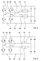
- FIG. 2 shows the right switching device 22 from FIG. 1 in a more detailed presentation.
- the switching device 22 comprises, in addition to an inverter circuit 58 for the independent power supply of the heating zones 12, 14, two switching elements 60, 62 for switching between sub-modes of the normal operating mode, in which either one of the heating zones 12, 14 or both heating zones 12, 14 are operated.
- the inverter circuit 58 comprises a total of four inverter diodes and four capacitors.
- the switching element 32 is integrated in the switching device 22.
- Analog shows FIG. 3 the left switching device 20 from FIG. 1 in a more detailed presentation.
- the switching device 20 comprises, in addition to an inverter circuit 56 for the independent power supply of the heating elements 16, 18 of the heating zone 10, two switching elements 64, 66 for switching between sub-modes of the normal operating mode in which either one of the heating elements 16, 18 or both heating elements 16, 18 of the heating zone 10 operated become.
- FIG. 4 shows the two switching devices 20, 22 and power supply devices 26, 28 in an alternative representation.
- Each of the switching devices 20, 22 comprises a microcontroller 48, 50, which is controlled by signals of the input unit 47.
- the input unit 47 also includes a central control unit for controlling an entire cooking appliance, which in addition to the induction hob also includes an oven not explicitly shown here.
- the microcontroller 48, 50 in turn each control an ASIC 52, 54 (Application Specific Integrated Circuit), which generates the high-frequency signals necessary for generating a high-frequency heating voltage and in the FIGS. 2 and 3 Inverter circuits 56, 58 shown in more detail.
- ASIC 52, 54 Application Specific Integrated Circuit
- the two switching devices 20, 22 are interconnected by a synchronization line 36 for synchronizing the power supply devices 26, 28 in the special mode of operation. If the special operating mode is activated, the ASIC 52 of the first switching device 20 operates as a master and transmits the Umrichtfrequenz U1 and a difference frequency DF to the operating as a slave further switching device 22 and to the corresponding ASIC 52 on. The microcontroller 50 of the further switching device 24 is thus disabled. In particular, a phase control signal can also be transmitted via this synchronization line 36.
- the first switching device 20 is designed so that in the special mode a differential frequency DF between a Umrichtfrequenz U1 of the first switching device 20 and a Umrichtfrequenz U2 of the second switching device 22 always has the value zero and therefore limited is.
- the difference frequency DF is always outside an audible frequency band of about 100 Hz to 10 kHz.
Landscapes
- Physics & Mathematics (AREA)
- Electromagnetism (AREA)
- General Induction Heating (AREA)
- Induction Heating Cooking Devices (AREA)
- Frying-Pans Or Fryers (AREA)
- Electric Stoves And Ranges (AREA)
Claims (12)
- Plaque de cuisson, notamment plaque de cuisson à induction, comprenant au moins une première zone de chauffe (10) qui comporte au moins deux éléments chauffants (16, 18) pouvant être chauffés de manière indépendante qui fonctionnent avec un premier dispositif d'alimentation en courant (26) par le biais d'un premier dispositif de commutation (20) dans un mode de fonctionnement normal, et comprenant au moins une autre zone de chauffe (12, 14) qui fonctionne avec un second dispositif d'alimentation en courant (28) par le biais d'un second dispositif de commutation (22) dans le mode de fonctionnement normal, caractérisée par au moins un élément de commutation (30, 32) pour l'établissement d'une connexion d'alimentation en courant entre le second dispositif d'alimentation en courant (28) et un des éléments chauffants (16, 18) de la première zone de chauffe (10) dans un mode de fonctionnement spécial pour augmenter une puissance de chauffe de la première zone de chauffe (10).
- Plaque de cuisson selon la revendication 1, caractérisée en ce que les éléments chauffants (16, 18) sont exécutés en tant que bobines d'induction.
- Plaque de cuisson selon la revendication 2, caractérisée par une ligne de synchronisation (36) pour synchroniser les dispositifs d'alimentation en courant (26, 28) dans le mode de fonctionnement spécial.
- Plaque de cuisson selon l'une des revendications précédentes, caractérisée par un moyen de commutation (34) pour l'activation manuelle du mode de fonctionnement spécial.
- Plaque de cuisson selon l'une des revendications précédentes, caractérisée en ce que l'autre zone de chauffe (12, 14) est désactivée dans le mode de fonctionnement spécial.
- Plaque de cuisson selon l'une des revendications précédentes, caractérisée par une ligne de connexion (38) pour connecter le second dispositif d'alimentation en courant (28) à l'un des éléments chauffants (16, 18) de la première zone de chauffe (10).
- Plaque de cuisson selon l'une des revendications précédentes, caractérisée en ce que l'un des dispositifs de commutation (20, 22) est prévu pour limiter une fréquence différentielle (DF) entre une fréquence de conversion (U1) du premier dispositif de commutation (20) et une fréquence de conversion (U2) du second dispositif de commutation (22).
- Plaque de cuisson selon la revendication 7, caractérisée en ce que le dispositif de commutation (20) est prévu pour déterminer la fréquence différentielle (DF) de manière à ce qu'elle soit située en dehors d'une bande de fréquence audible.
- Plaque de cuisson selon l'une des revendications précédentes, caractérisée par un dispositif de commutation (24) pour modifier les connexions entre les dispositifs d'alimentation en courant (26, 28) et les zones de chauffe (10, 12, 14) pour commuter entre le mode de fonctionnement normal et le mode de fonctionnement spécial.
- Plaque de cuisson selon l'une des revendications précédentes, caractérisée en ce qu'un premier élément de commutation (30) pour séparer un premier élément chauffant (18) de la première zone de chauffe (10) du premier dispositif d'alimentation en courant (26) est situé dans le premier dispositif de commutation (20).
- Plaque de cuisson selon la revendication 10, caractérisée en ce que l'élément de commutation (32) pour connecter le premier élément chauffant (18) de la première zone de chauffe (10) au second dispositif d'alimentation en courant (28) est situé dans le second dispositif de commutation (22).
- Procédé pour faire fonctionner une plaque de cuisson, notamment une plaque de cuisson à induction, comprenant au moins une première zone de chauffe (10) qui comporte au moins deux éléments chauffants (16, 18) pouvant être chauffés de manière indépendante, les deux éléments chauffants (16, 18) fonctionnant avec un premier dispositif d'alimentation en courant (26) par le biais d'un premier dispositif de commutation (20) dans un mode de fonctionnement normal, et au moins une autre zone de chauffe (12, 14) fonctionnant avec un second dispositif d'alimentation en courant (28) par le biais d'un second dispositif de commutation (22), caractérisée en ce que, pour enclencher et déclencher un mode de fonctionnement spécial pour augmenter une puissance de chauffe de la première zone de chauffe (10), on actionne un élément de commutation (30, 32) pour l'établissement d'une connexion d'alimentation en courant entre le second dispositif d'alimentation en courant (28) et un des éléments chauffants (16, 18) de la première zone de chauffe (10).
Applications Claiming Priority (2)
| Application Number | Priority Date | Filing Date | Title |
|---|---|---|---|
| ES200502708A ES2300168B1 (es) | 2005-10-27 | 2005-10-27 | Encimera de cocina y procedimiento para el funcionamiento de una encimera de cocina. |
| PCT/EP2006/067220 WO2007048700A1 (fr) | 2005-10-27 | 2006-10-10 | Plaque de cuisson et procede permettant de faire fonctionner une plaque de cuisson |
Publications (2)
| Publication Number | Publication Date |
|---|---|
| EP1943878A1 EP1943878A1 (fr) | 2008-07-16 |
| EP1943878B1 true EP1943878B1 (fr) | 2009-03-25 |
Family
ID=37771087
Family Applications (1)
| Application Number | Title | Priority Date | Filing Date |
|---|---|---|---|
| EP06807106A Active EP1943878B1 (fr) | 2005-10-27 | 2006-10-10 | Plaque de cuisson et procede permettant de faire fonctionner une plaque de cuisson |
Country Status (7)
| Country | Link |
|---|---|
| US (1) | US8963054B2 (fr) |
| EP (1) | EP1943878B1 (fr) |
| CN (1) | CN101297601B (fr) |
| AT (1) | ATE427024T1 (fr) |
| DE (1) | DE502006003290D1 (fr) |
| ES (2) | ES2300168B1 (fr) |
| WO (1) | WO2007048700A1 (fr) |
Families Citing this family (37)
| Publication number | Priority date | Publication date | Assignee | Title |
|---|---|---|---|---|
| ES2329211B1 (es) * | 2007-08-07 | 2010-08-30 | Bsh Electrodomesticos España, S.A. | Circuito de dispositivo de coccion. |
| ES2398290T3 (es) | 2007-09-05 | 2013-03-15 | Whirlpool Corporation | Aparato de cocción por inducción mejorado y método para comprobar las capacidades de cocción de una pieza de batería de cocina |
| CN102177765B (zh) * | 2008-10-08 | 2013-10-02 | 松下电器产业株式会社 | 感应加热装置 |
| ES2347403B1 (es) * | 2008-12-19 | 2011-08-17 | Bsh Electrodomesticos España, S.A. | Campo de coccion por induccion y procedimiento para accionar un campode coccion por induccion. |
| ES2352772B1 (es) * | 2008-12-19 | 2012-01-26 | Bsh Electrodomésticos España, S.A. | Campo de cocción con varios elementos de calentamiento y al menos un grupo constructivo de la electrónica de potencia. |
| ES2353890B1 (es) * | 2008-12-19 | 2012-01-26 | Bsh Electrodomesticos España, S.A. | Campo de cocción con al menos tres zonas de calentamiento. |
| EP2209350B1 (fr) | 2009-01-16 | 2018-11-28 | Whirlpool Corporation | Procédé pour la synchronisation de bobines d'induction par des convertisseurs de puissance d'une plaque de cuisson par induction et système de chauffage par induction pour réaliser ledit procédé |
| TWI394547B (zh) * | 2009-03-18 | 2013-05-01 | Delta Electronics Inc | 加熱裝置 |
| EP3771288B1 (fr) | 2009-10-05 | 2021-12-15 | Whirlpool Corporation | Procédé de fourniture de puissance à des zones de cuisson par induction d'une plaque de cuisson par induction dotée d'une pluralité de convertisseurs de puissance, et plaque de cuisson par induction utilisant ledit procédé |
| ES2382862B1 (es) * | 2009-10-26 | 2013-05-08 | BSH Electrodomésticos España S.A. | Encimera de cocción con al menos dos elementos de calentamiento y una disposición de la electrónica de potencia |
| ITTO20090942A1 (it) | 2009-12-01 | 2011-06-02 | Indesit Co Spa | Piano cottura e metodo per il suo controllo |
| ES2384919B1 (es) * | 2009-12-28 | 2013-05-20 | Bsh Electrodomésticos España, S.A. | Dispositivo de aparato de cocción. |
| ES2388028B1 (es) * | 2010-03-03 | 2013-08-23 | Bsh Electrodomésticos España, S.A. | Encimera de cocción con al menos una zona de cocción y procedimiento para accionar una encimera de cocción. |
| CN102792770B (zh) * | 2010-03-04 | 2015-02-11 | 三菱电机株式会社 | 感应加热烹调器 |
| ES2678499T3 (es) * | 2010-05-28 | 2018-08-13 | Mitsubishi Electric Corporation | Sistema de cocción por inducción |
| EP2651182B1 (fr) * | 2011-01-19 | 2021-12-15 | Electrolux Home Products Corporation N.V. | Table de cuisson par induction comprenant quatre zones de chauffage |
| RU2567853C2 (ru) * | 2011-03-30 | 2015-11-10 | Бсх Хаусгерете Гмбх | Индукционное нагревательное устройство |
| EP2692205A1 (fr) * | 2011-03-31 | 2014-02-05 | BSH Bosch und Siemens Hausgeräte GmbH | Dispositif de chauffage par induction |
| ES2432235B1 (es) * | 2012-05-30 | 2014-11-04 | Bsh Electrodomésticos España, S.A. | Dispositivo de calentamiento por inducción |
| WO2014167814A1 (fr) * | 2013-04-10 | 2014-10-16 | パナソニック株式会社 | Dispositif chauffant à induction |
| EP3024300B1 (fr) * | 2013-09-05 | 2017-08-30 | Electrolux Appliances Aktiebolag | Table de cuisson par induction comprenant une zone de cuisson avec trois ou plusieurs bobines d'induction et procédé permettant de commander une zone de cuisson |
| ES2538605B1 (es) * | 2013-12-20 | 2016-04-15 | Bsh Electrodomésticos España, S.A. | Dispositivo de campo de cocción |
| US10024545B2 (en) | 2014-04-17 | 2018-07-17 | Whirlpool Corporation | Power management for home appliances |
| WO2016071824A1 (fr) * | 2014-11-06 | 2016-05-12 | BSH Hausgeräte GmbH | Dispositif pour appareil de cuisson |
| US10455647B2 (en) * | 2014-11-26 | 2019-10-22 | Samsung Electronics Co., Ltd. | Cooking apparatus and method for controlling the same |
| KR102388214B1 (ko) * | 2015-06-22 | 2022-04-20 | 엘지전자 주식회사 | 전자 유도 가열 조리기 |
| CN105050217A (zh) * | 2015-07-28 | 2015-11-11 | 阳春丽 | 一种串联谐振式感应加热电源同步运行方法 |
| DE102015118397A1 (de) | 2015-10-28 | 2017-05-04 | Frima International Ag | Verfahren zur Steuerung eines Gargeräts, Gargerät und Heizelement |
| EP3209093B1 (fr) | 2016-02-19 | 2018-09-12 | Electrolux Appliances Aktiebolag | Module à induction et table de cuisson à induction |
| EP3424270B1 (fr) | 2016-03-04 | 2019-10-09 | Arçelik Anonim Sirketi | Appareil de cuisson à chauffage par induction avec dispositif de chauffage à bobine et procédé de détection de récipient |
| WO2017149111A1 (fr) | 2016-03-04 | 2017-09-08 | Arcelik Anonim Sirketi | Appareil de cuisson à chauffage par induction doté d'un dispositif de chauffage à double bobine et procédé de détection de récipient |
| WO2017174630A1 (fr) | 2016-04-06 | 2017-10-12 | Arcelik Anonim Sirketi | Table de cuisson à chauffage par induction comprenant une zone de chauffage à double bobine |
| EP3282815B1 (fr) * | 2016-08-08 | 2019-05-15 | Electrolux Appliances Aktiebolag | Procédé de commande d'une plaque de cuisson à induction |
| KR101851889B1 (ko) * | 2017-01-12 | 2018-06-07 | 엘지전자 주식회사 | 유도 가열 조리기 |
| EP3445135B1 (fr) * | 2017-08-14 | 2020-05-27 | Electrolux Appliances Aktiebolag | Module de puissance et appareil de cuisson |
| KR102541269B1 (ko) | 2018-06-25 | 2023-06-09 | 삼성전자주식회사 | 조리 기기 및 이의 제어 방법 |
| KR102525461B1 (ko) * | 2018-08-09 | 2023-04-24 | 엘지전자 주식회사 | 간섭 소음을 줄일 수 있는 유도 가열 장치 |
Family Cites Families (8)
| Publication number | Priority date | Publication date | Assignee | Title |
|---|---|---|---|---|
| US4755655A (en) * | 1986-12-04 | 1988-07-05 | General Electric Company | Thermal protection arrangement for solid disk glass cooktop |
| KR0179529B1 (ko) * | 1995-12-27 | 1999-05-15 | 구자홍 | 다출력 제어를 위한 듀얼 할프 브리지형 전자 유도 가열 조리 장치 |
| FR2773014B1 (fr) * | 1997-12-23 | 2000-03-03 | Europ Equip Menager | Dispositif d'alimentation de plusieurs circuits resonants par un generateur de puissance a onduleur |
| US6528770B1 (en) * | 1999-04-09 | 2003-03-04 | Jaeger Regulation | Induction cooking hob with induction heaters having power supplied by generators |
| ATE408261T1 (de) | 2000-09-29 | 2008-09-15 | Bsh Bosch Siemens Hausgeraete | Umrichterschaltung und verfahren zum betrieb einer solchen |
| ES2211303B1 (es) * | 2002-08-01 | 2005-10-01 | Bsh Electrodomesticos España, S.A. | Placa de cocina de induccion con zonas de calentamiento de estructura reconfigurable y procedimiento para incrementar la potencia maxima de dichas zonas de calentamiento. |
| FR2850216B1 (fr) * | 2003-01-21 | 2005-04-08 | Brandt Ind | Generateur d'alimentation d'un circuit oscillant, notamment pour table de cuisson par induction. |
| ES2201937B1 (es) * | 2003-11-03 | 2005-02-01 | Bsh Electrodomesticos España, S.A. | Procedimiento para el funcionamiento de un circuito convertidor. |
-
2005
- 2005-10-27 ES ES200502708A patent/ES2300168B1/es not_active Expired - Fee Related
-
2006
- 2006-10-10 EP EP06807106A patent/EP1943878B1/fr active Active
- 2006-10-10 AT AT06807106T patent/ATE427024T1/de not_active IP Right Cessation
- 2006-10-10 US US12/084,163 patent/US8963054B2/en not_active Expired - Fee Related
- 2006-10-10 DE DE502006003290T patent/DE502006003290D1/de active Active
- 2006-10-10 ES ES06807106T patent/ES2322671T3/es active Active
- 2006-10-10 WO PCT/EP2006/067220 patent/WO2007048700A1/fr active Application Filing
- 2006-10-10 CN CN2006800398099A patent/CN101297601B/zh not_active Expired - Fee Related
Also Published As
| Publication number | Publication date |
|---|---|
| CN101297601B (zh) | 2011-05-04 |
| ATE427024T1 (de) | 2009-04-15 |
| US20090139980A1 (en) | 2009-06-04 |
| ES2300168B1 (es) | 2009-05-08 |
| DE502006003290D1 (de) | 2009-05-07 |
| ES2300168A1 (es) | 2008-06-01 |
| US8963054B2 (en) | 2015-02-24 |
| ES2322671T3 (es) | 2009-06-24 |
| CN101297601A (zh) | 2008-10-29 |
| WO2007048700A1 (fr) | 2007-05-03 |
| EP1943878A1 (fr) | 2008-07-16 |
Similar Documents
| Publication | Publication Date | Title |
|---|---|---|
| EP1943878B1 (fr) | Plaque de cuisson et procede permettant de faire fonctionner une plaque de cuisson | |
| EP2342943B1 (fr) | Plaque de cuisson et procédé permettant de faire fonctionner une plaque de cuisson | |
| EP1878309B1 (fr) | Procede et dispositif d'alimentation electrique de plusieurs bobines d'induction d'un appareil d'induction | |
| EP2380395B1 (fr) | Table de cuisson avec au moins trois zones de cuisson | |
| EP2034800B1 (fr) | Commutateur de dispositif de cuisson | |
| DE602005003310T2 (de) | Umrichterschaltung für Induktionsheizvorrichtung, Kochgerät mit einer solchen Schaltung und Betriebsverfahren | |
| EP2380399B1 (fr) | Table de cuisson comprenant plusieurs éléments chauffants et au moins un module d'électronique de puissance | |
| EP2206407B1 (fr) | Dispositif de cuisson | |
| EP2494846B1 (fr) | Plaque de cuisson à au moins deux résistances, et dispositif électronique de puissance | |
| EP2543231B1 (fr) | Plaque de cuisson comportant au moins une zone de cuisson, ainsi que procédé pour faire fonctionner une plaque de cuisson | |
| WO2005043737A2 (fr) | Procede d'utilisation d'un circuit de convertisseur | |
| EP1935213A1 (fr) | Procede pour faire fonctionner un systeme de chauffage par induction | |
| EP3706510A1 (fr) | Procédé de commande d'une bobine d'induction et dispositif de bobine d'induction | |
| DE102010001770A1 (de) | Wechselrichter zum Betreiben von Unterhaltungs-Elektronikgeräten in einem Fahrzeug | |
| EP2469970B1 (fr) | Dispositif d'appareil de cuisson | |
| EP2520131B1 (fr) | Système d'appareil de cuisson | |
| DE10017176B4 (de) | Induktionskochplatte mit von Generatoren gespeisten Induktionsheizelementen | |
| DE19707159C2 (de) | Einrichtung zum induktiven Beheizen von Behältern | |
| EP4413832A1 (fr) | Système de transmission d'énergie par induction | |
| EP3664578B1 (fr) | Dispositif formant appareil de cuisson | |
| WO2008031560A1 (fr) | Système de chauffage par induction | |
| WO2024046640A1 (fr) | Système de transmission d'énergie par induction | |
| WO2023104886A1 (fr) | Dispositif de table de cuisson à induction | |
| WO2020239821A1 (fr) | Dispositif formant appareil de cuisson | |
| EP2945461A1 (fr) | Dispositif d'appareil de cuisson |
Legal Events
| Date | Code | Title | Description |
|---|---|---|---|
| PUAI | Public reference made under article 153(3) epc to a published international application that has entered the european phase |
Free format text: ORIGINAL CODE: 0009012 |
|
| 17P | Request for examination filed |
Effective date: 20080527 |
|
| AK | Designated contracting states |
Kind code of ref document: A1 Designated state(s): AT BE BG CH CY CZ DE DK EE ES FI FR GB GR HU IE IS IT LI LT LU LV MC NL PL PT RO SE SI SK TR |
|
| GRAP | Despatch of communication of intention to grant a patent |
Free format text: ORIGINAL CODE: EPIDOSNIGR1 |
|
| DAX | Request for extension of the european patent (deleted) | ||
| GRAS | Grant fee paid |
Free format text: ORIGINAL CODE: EPIDOSNIGR3 |
|
| GRAA | (expected) grant |
Free format text: ORIGINAL CODE: 0009210 |
|
| AK | Designated contracting states |
Kind code of ref document: B1 Designated state(s): AT BE BG CH CY CZ DE DK EE ES FI FR GB GR HU IE IS IT LI LT LU LV MC NL PL PT RO SE SI SK TR |
|
| REG | Reference to a national code |
Ref country code: GB Ref legal event code: FG4D Free format text: NOT ENGLISH |
|
| REG | Reference to a national code |
Ref country code: CH Ref legal event code: EP |
|
| REG | Reference to a national code |
Ref country code: IE Ref legal event code: FG4D Free format text: LANGUAGE OF EP DOCUMENT: GERMAN |
|
| REF | Corresponds to: |
Ref document number: 502006003290 Country of ref document: DE Date of ref document: 20090507 Kind code of ref document: P |
|
| REG | Reference to a national code |
Ref country code: ES Ref legal event code: FG2A Ref document number: 2322671 Country of ref document: ES Kind code of ref document: T3 |
|
| PG25 | Lapsed in a contracting state [announced via postgrant information from national office to epo] |
Ref country code: SI Free format text: LAPSE BECAUSE OF FAILURE TO SUBMIT A TRANSLATION OF THE DESCRIPTION OR TO PAY THE FEE WITHIN THE PRESCRIBED TIME-LIMIT Effective date: 20090325 Ref country code: LT Free format text: LAPSE BECAUSE OF FAILURE TO SUBMIT A TRANSLATION OF THE DESCRIPTION OR TO PAY THE FEE WITHIN THE PRESCRIBED TIME-LIMIT Effective date: 20090325 Ref country code: FI Free format text: LAPSE BECAUSE OF FAILURE TO SUBMIT A TRANSLATION OF THE DESCRIPTION OR TO PAY THE FEE WITHIN THE PRESCRIBED TIME-LIMIT Effective date: 20090325 |
|
| PG25 | Lapsed in a contracting state [announced via postgrant information from national office to epo] |
Ref country code: SE Free format text: LAPSE BECAUSE OF FAILURE TO SUBMIT A TRANSLATION OF THE DESCRIPTION OR TO PAY THE FEE WITHIN THE PRESCRIBED TIME-LIMIT Effective date: 20090625 Ref country code: LV Free format text: LAPSE BECAUSE OF FAILURE TO SUBMIT A TRANSLATION OF THE DESCRIPTION OR TO PAY THE FEE WITHIN THE PRESCRIBED TIME-LIMIT Effective date: 20090325 Ref country code: PL Free format text: LAPSE BECAUSE OF FAILURE TO SUBMIT A TRANSLATION OF THE DESCRIPTION OR TO PAY THE FEE WITHIN THE PRESCRIBED TIME-LIMIT Effective date: 20090325 |
|
| NLV1 | Nl: lapsed or annulled due to failure to fulfill the requirements of art. 29p and 29m of the patents act | ||
| REG | Reference to a national code |
Ref country code: IE Ref legal event code: FD4D |
|
| PG25 | Lapsed in a contracting state [announced via postgrant information from national office to epo] |
Ref country code: EE Free format text: LAPSE BECAUSE OF FAILURE TO SUBMIT A TRANSLATION OF THE DESCRIPTION OR TO PAY THE FEE WITHIN THE PRESCRIBED TIME-LIMIT Effective date: 20090325 Ref country code: CZ Free format text: LAPSE BECAUSE OF FAILURE TO SUBMIT A TRANSLATION OF THE DESCRIPTION OR TO PAY THE FEE WITHIN THE PRESCRIBED TIME-LIMIT Effective date: 20090325 Ref country code: PT Free format text: LAPSE BECAUSE OF FAILURE TO SUBMIT A TRANSLATION OF THE DESCRIPTION OR TO PAY THE FEE WITHIN THE PRESCRIBED TIME-LIMIT Effective date: 20090831 |
|
| PG25 | Lapsed in a contracting state [announced via postgrant information from national office to epo] |
Ref country code: RO Free format text: LAPSE BECAUSE OF FAILURE TO SUBMIT A TRANSLATION OF THE DESCRIPTION OR TO PAY THE FEE WITHIN THE PRESCRIBED TIME-LIMIT Effective date: 20090325 Ref country code: NL Free format text: LAPSE BECAUSE OF FAILURE TO SUBMIT A TRANSLATION OF THE DESCRIPTION OR TO PAY THE FEE WITHIN THE PRESCRIBED TIME-LIMIT Effective date: 20090325 Ref country code: SK Free format text: LAPSE BECAUSE OF FAILURE TO SUBMIT A TRANSLATION OF THE DESCRIPTION OR TO PAY THE FEE WITHIN THE PRESCRIBED TIME-LIMIT Effective date: 20090325 Ref country code: IS Free format text: LAPSE BECAUSE OF FAILURE TO SUBMIT A TRANSLATION OF THE DESCRIPTION OR TO PAY THE FEE WITHIN THE PRESCRIBED TIME-LIMIT Effective date: 20090725 |
|
| PG25 | Lapsed in a contracting state [announced via postgrant information from national office to epo] |
Ref country code: IE Free format text: LAPSE BECAUSE OF FAILURE TO SUBMIT A TRANSLATION OF THE DESCRIPTION OR TO PAY THE FEE WITHIN THE PRESCRIBED TIME-LIMIT Effective date: 20090325 Ref country code: BG Free format text: LAPSE BECAUSE OF FAILURE TO SUBMIT A TRANSLATION OF THE DESCRIPTION OR TO PAY THE FEE WITHIN THE PRESCRIBED TIME-LIMIT Effective date: 20090625 Ref country code: DK Free format text: LAPSE BECAUSE OF FAILURE TO SUBMIT A TRANSLATION OF THE DESCRIPTION OR TO PAY THE FEE WITHIN THE PRESCRIBED TIME-LIMIT Effective date: 20090325 |
|
| PLBE | No opposition filed within time limit |
Free format text: ORIGINAL CODE: 0009261 |
|
| STAA | Information on the status of an ep patent application or granted ep patent |
Free format text: STATUS: NO OPPOSITION FILED WITHIN TIME LIMIT |
|
| 26N | No opposition filed |
Effective date: 20091229 |
|
| BERE | Be: lapsed |
Owner name: BSH BOSCH UND SIEMENS HAUSGERATE G.M.B.H. Effective date: 20091031 |
|
| PG25 | Lapsed in a contracting state [announced via postgrant information from national office to epo] |
Ref country code: MC Free format text: LAPSE BECAUSE OF NON-PAYMENT OF DUE FEES Effective date: 20091031 |
|
| PG25 | Lapsed in a contracting state [announced via postgrant information from national office to epo] |
Ref country code: BE Free format text: LAPSE BECAUSE OF NON-PAYMENT OF DUE FEES Effective date: 20091031 |
|
| PG25 | Lapsed in a contracting state [announced via postgrant information from national office to epo] |
Ref country code: AT Free format text: LAPSE BECAUSE OF NON-PAYMENT OF DUE FEES Effective date: 20091010 |
|
| PG25 | Lapsed in a contracting state [announced via postgrant information from national office to epo] |
Ref country code: LU Free format text: LAPSE BECAUSE OF NON-PAYMENT OF DUE FEES Effective date: 20091010 |
|
| REG | Reference to a national code |
Ref country code: CH Ref legal event code: PL |
|
| PG25 | Lapsed in a contracting state [announced via postgrant information from national office to epo] |
Ref country code: HU Free format text: LAPSE BECAUSE OF FAILURE TO SUBMIT A TRANSLATION OF THE DESCRIPTION OR TO PAY THE FEE WITHIN THE PRESCRIBED TIME-LIMIT Effective date: 20090926 |
|
| PG25 | Lapsed in a contracting state [announced via postgrant information from national office to epo] |
Ref country code: LI Free format text: LAPSE BECAUSE OF NON-PAYMENT OF DUE FEES Effective date: 20101031 Ref country code: CH Free format text: LAPSE BECAUSE OF NON-PAYMENT OF DUE FEES Effective date: 20101031 |
|
| PG25 | Lapsed in a contracting state [announced via postgrant information from national office to epo] |
Ref country code: CY Free format text: LAPSE BECAUSE OF FAILURE TO SUBMIT A TRANSLATION OF THE DESCRIPTION OR TO PAY THE FEE WITHIN THE PRESCRIBED TIME-LIMIT Effective date: 20090325 |
|
| PG25 | Lapsed in a contracting state [announced via postgrant information from national office to epo] |
Ref country code: GR Free format text: LAPSE BECAUSE OF FAILURE TO SUBMIT A TRANSLATION OF THE DESCRIPTION OR TO PAY THE FEE WITHIN THE PRESCRIBED TIME-LIMIT Effective date: 20090325 |
|
| REG | Reference to a national code |
Ref country code: DE Ref legal event code: R081 Ref document number: 502006003290 Country of ref document: DE Owner name: BSH HAUSGERAETE GMBH, DE Free format text: FORMER OWNER: BSH BOSCH UND SIEMENS HAUSGERAETE GMBH, 81739 MUENCHEN, DE Effective date: 20150407 |
|
| REG | Reference to a national code |
Ref country code: ES Ref legal event code: PC2A Owner name: BSH HAUSGERATE GMBH Effective date: 20150609 |
|
| REG | Reference to a national code |
Ref country code: FR Ref legal event code: PLFP Year of fee payment: 10 |
|
| REG | Reference to a national code |
Ref country code: FR Ref legal event code: CD Owner name: BSH HAUSGERATE GMBH, DE Effective date: 20151022 |
|
| REG | Reference to a national code |
Ref country code: FR Ref legal event code: PLFP Year of fee payment: 11 |
|
| REG | Reference to a national code |
Ref country code: FR Ref legal event code: PLFP Year of fee payment: 12 |
|
| REG | Reference to a national code |
Ref country code: FR Ref legal event code: PLFP Year of fee payment: 13 |
|
| PGFP | Annual fee paid to national office [announced via postgrant information from national office to epo] |
Ref country code: TR Payment date: 20191004 Year of fee payment: 14 |
|
| PG25 | Lapsed in a contracting state [announced via postgrant information from national office to epo] |
Ref country code: TR Free format text: LAPSE BECAUSE OF NON-PAYMENT OF DUE FEES Effective date: 20201010 |
|
| P01 | Opt-out of the competence of the unified patent court (upc) registered |
Effective date: 20230504 |
|
| PGFP | Annual fee paid to national office [announced via postgrant information from national office to epo] |
Ref country code: GB Payment date: 20231025 Year of fee payment: 18 |
|
| PGFP | Annual fee paid to national office [announced via postgrant information from national office to epo] |
Ref country code: ES Payment date: 20231117 Year of fee payment: 18 |
|
| PGFP | Annual fee paid to national office [announced via postgrant information from national office to epo] |
Ref country code: IT Payment date: 20231031 Year of fee payment: 18 Ref country code: FR Payment date: 20231023 Year of fee payment: 18 Ref country code: DE Payment date: 20231031 Year of fee payment: 18 |