EP1943804B1 - Method and devices for the transfer of a data flow from a data source to a data sink - Google Patents
Method and devices for the transfer of a data flow from a data source to a data sink Download PDFInfo
- Publication number
- EP1943804B1 EP1943804B1 EP06807499.6A EP06807499A EP1943804B1 EP 1943804 B1 EP1943804 B1 EP 1943804B1 EP 06807499 A EP06807499 A EP 06807499A EP 1943804 B1 EP1943804 B1 EP 1943804B1
- Authority
- EP
- European Patent Office
- Prior art keywords
- data
- identifier
- data packet
- trick mode
- packet
- Prior art date
- Legal status (The legal status is an assumption and is not a legal conclusion. Google has not performed a legal analysis and makes no representation as to the accuracy of the status listed.)
- Active
Links
- 238000012546 transfer Methods 0.000 title claims description 35
- 238000000034 method Methods 0.000 title claims description 18
- 230000015654 memory Effects 0.000 claims description 37
- 238000004891 communication Methods 0.000 claims description 10
- 230000008859 change Effects 0.000 description 8
- 230000006870 function Effects 0.000 description 6
- 230000007704 transition Effects 0.000 description 4
- 238000010586 diagram Methods 0.000 description 3
- 230000004044 response Effects 0.000 description 3
- 230000009471 action Effects 0.000 description 2
- 230000006399 behavior Effects 0.000 description 1
- 230000005540 biological transmission Effects 0.000 description 1
- 230000001934 delay Effects 0.000 description 1
- 238000012217 deletion Methods 0.000 description 1
- 230000037430 deletion Effects 0.000 description 1
- 238000001514 detection method Methods 0.000 description 1
- 238000011161 development Methods 0.000 description 1
- 230000018109 developmental process Effects 0.000 description 1
- 238000011835 investigation Methods 0.000 description 1
- 230000006855 networking Effects 0.000 description 1
- 230000008569 process Effects 0.000 description 1
Images


Classifications
-
- H—ELECTRICITY
- H04—ELECTRIC COMMUNICATION TECHNIQUE
- H04L—TRANSMISSION OF DIGITAL INFORMATION, e.g. TELEGRAPHIC COMMUNICATION
- H04L12/00—Data switching networks
- H04L12/02—Details
- H04L12/16—Arrangements for providing special services to substations
-
- H—ELECTRICITY
- H04—ELECTRIC COMMUNICATION TECHNIQUE
- H04L—TRANSMISSION OF DIGITAL INFORMATION, e.g. TELEGRAPHIC COMMUNICATION
- H04L65/00—Network arrangements, protocols or services for supporting real-time applications in data packet communication
- H04L65/1066—Session management
- H04L65/1101—Session protocols
-
- H—ELECTRICITY
- H04—ELECTRIC COMMUNICATION TECHNIQUE
- H04L—TRANSMISSION OF DIGITAL INFORMATION, e.g. TELEGRAPHIC COMMUNICATION
- H04L65/00—Network arrangements, protocols or services for supporting real-time applications in data packet communication
- H04L65/60—Network streaming of media packets
- H04L65/65—Network streaming protocols, e.g. real-time transport protocol [RTP] or real-time control protocol [RTCP]
Definitions
- the invention relates to the technical field of trick mode replay of multimedia contents, especially video or audio contents with special reference to the trick mode generation in a network environment, such as a home network, for example.
- AVi Home Audio/Video interoperability
- UPnP Universal Plug and Play
- the transfer of AV data flows has been particularly taken into account in these network systems since the HAVi system has been primarily developed for this case of application, and with regard to the UPnP system, a working group of the UPnP forum developed a UPnP AV specification which is based on the general UPnP specification and expands it.
- the designation of this specification is UPnP AV Architecture: 0.83 of 12 June 2002.
- the mentioned specifications support the detection of AV devices, setting up AV connections, finding AV contents, operating the data source and data sink device, replay of selected AV contents in the mode of normal replay and in trick mode replay, etc.
- Trick mode replay shows a behavior which is problematic.
- device A is a data source - such as, e.g. a digital video recorder which is hard disk based and has AV contents stored.
- Device B should serve as data sink, e.g. as a display device. Both devices are provided with a communication interface for data exchange as well as for the exchange of control commands.
- data transfer (which can be done e.g. in TCP/IP based networks via HTTP or via RTP), the data must, as a rule, go through different buffer memories.
- the transfer network itself can also be considered a memory in this sense because even this transfer can result in delays on the net.
- the replay of AV contents is relatively simple in case of normal replay (thus with simple replay speed).
- the devices Via the communication interface, the devices are informed which content is to be sent where and, respectively, what they are to receive; and then, replay can start.
- trick modes fast forward, fast reverse, slow motion, still image.
- a case will be considered where the AV system is in normal replay mode and will then be switched, without pause, to a higher forward speed, e.g. triple search function.
- the device A supports so-called "server side” trick modes, i.e. that the source will modify the data flow such that the receiver will receive a valid data flow from which the images not to be shown have already been removed. For that, a corresponding trick mode module is looped into the data path in device A.
- the data generated by this module must now run through the memories on the transfer path, e.g. a sender memory, a receiver memory, and a buffer memory for the data decoder. That means the data still existing in these memories at the time of switching must actually still be decoded by the decoder in device B before the trick mode specific data can be decoded.
- WO 98/34405 relates to improved techniques for displaying video images transmitted over a computer network.
- EP1531601 relates to the techical field of data transmission in a network of distributed stations, in particular in a so-called domestic network.
- the object of the invention to provide a method and corresponding devices by means of which the mentioned time delay can be minimized so that the user will find the system less sluggish.
- the solution according to the invention is based on the deletion of data which was still present in the memories upon the user's request to change into trick mode. To do this, a measure is proposed which is carried out in the receiver device. That device will actually receive the irrelevant data, but will not decode it, rather ignore it instead. Yet, for its realization, the receiver device must know when the relevant data begins (in the example that belonging to the newly set trick mode). This problem will be solved by embedding additional control data in the AV data flow. The additional control data identify the subsequent AV data as uniquely belonging to a specific action.
- the additional control data are not only once integrated into the data flow but will be repeated at regular intervals.
- any possible loss of data on the transfer path e.g. caused by intervening wireless data connections
- additional data sinks - connected at a later point in time with a data source already sending data - would receive information about the command triggering the sending or, respectively, the current operating mode of the data source device.
- the operating mode identifier will be integrated - within the scope of the OSI/ISO layer model of data communication - in the data flow on the transport layer since this will not require any manipulation of the useful load data flow.
- an operating mode suggests itself especially in trick mode replay - that of the so-called chunked transfer encoding according to the HTTP 1.1 specification.
- the useful data are transferred in blocks of various length, the block length being transferred as a hexadecimal number before the actual block.
- this transfer mode it is possible to also insert comment text behind the indication of the block length, separated by a semicolon. It is precisely this comment text which can be used for the transfer of the said identifier within the scope of the invention.
- a so-called X-bit can be set in the header of the RTP packet.
- an additional header can be added to the standard header as a so-called "RTP header extension".
- the identifier according to the invention can also be inserted in this additional header.
- the data source device inserts additional information into the AV data flow which will allow device B to determine the exact position information.
- the data sink device informs the data source device up to which point the decoding has progressed. The data source device can then re-align the trick mode replay to precisely this point and start with the trick mode data flow generation at the point where the replay had been interrupted before.
- the data sink device can identify the point at which replay was interrupted.
- the time code information can also be used, for example, in the data sink device at the same time as a source information for displaying a replay counter.
- Claims 8 and 9 list correspondingly advantageous measures for a data sink device according to the invention.
- Claims 10 to 16 list advantageous measures for a data source device according to the invention.
- the invention can also be advantageously used when data source and data sink are not positioned in different devices connected by a network but are instead provided in a single device.
- Claim 17 lists the measures according to the invention for such a device for performing the method according to the invention.
- FIG. 1 shows a digital video recorder DVR with the reference number 10. It is provided with mass storage to store video and audio contents. Today's standard digital video recorders have a hard disk for this purpose.
- the reference number 20 designates a digital TV device, DTV. This may be a flat screen device, such as LCD or plasma TV, with an integrated decoder for digital audio and video signals.
- the reference number 30 designates a DVD player. All devices 10 to 30 are networked.
- a network connecting switch unit 40 is provided for this which is also known as "network switch" or "router", respectively.
- the data in the network can be transferred according to the Ethernet protocol.
- the commercially available Ethernet network cables can be used as network cables. For the transfer of AV data flows, the use of a network cable for 100 Mbit Ethernet will be already adequate since the data are transferred in compressed condition.
- Reference number 50 designates a personal computer and reference number 60 a printer. These two devices are connected via their own network connection switch unit 80 to the rest of the network. Additionally, the network comprises a personal data assistant 70 as a network user station. This device is, however, wirelessly connected with the network via a corresponding wireless connection route which is supported by the network connection switch unit 80.
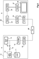
- Figure 2 shows the two devices - data source device 10 and data sink device 20 - which are connected with each other, and their structure by means of the pertinent rough block diagrams.
- a hard disk 11 is provided as mass storage in the digital video recorder 10. When reading data from the hard disk 11, the data read will first go into a read memory 12. It is supposed that the data in mass storage 11 are already stored in coded form, compressed. In normal replay, the data are not recoded so that the data path goes from the hard disk 11 via the read memory 12 directly to the sending memory 14; and from there, the data are transferred via the communication interface 15 via the network to the data sink device 20.
- the algorithms known in the state of the art for filling the sending memory 14 can be used in the data source device 10.
- trick modes will be the known modes of fast forward, fast reverse, slow motion, as well as still image replay.
- the data are stored in compressed condition and encoded in the mass storage 11. If e.g. the MPEG2 encoding method is used for video coding, switching into a trick mode of any speed will require that the data are recoded.
- three different types of images are used according to the MPEG2 video encoding method. These are intra-coded images I, unidirectionally predicated images P, as well as bidirectionally predicated images B.
- the different types of images can appear in the data flow according to the MPEG2 standard in determinate or arbitrary sequence. Since the I and P images depend on the preceding or, respectively, succeeding images, they cannot simply be transferred singularly but only together with the pertinent basic images. This is one difficulty in the realization of trick modes. For this reason, it has been suggested in the state of the art to actually decode the MPEG2 data flow existing in mass storage to generate trick mode replays, and then re-encode them to have again new freedom in the selection of the images to be transferred. For this, it has been suggested in the state of the art to actually decode the MPEG2 data flow existing in mass storage to generate trick mode replays, and then re-encode them to have again new freedom in the selection of the images to be transferred. For this, a trick mode generator 13 is provided in the data source device 10. Said generator will be looped in the data path upon switching over to trick mode replay. The MPEG2 data present in the read memory 12 will then be recoded so that a new MPEG2 data flow is
- the transferred data get via the network into the data sink device 20.
- this is a digital TV device which comprises as major components a decoder 21 and a display unit 26. It is assumed that a plasma or LCD panel is used as a display unit.
- the decoder 21 is an MPEG2 decoder, for example.
- a buffer memory 22 is assigned to it as a decoding memory. However, the data first pass into the device via the communication interface 25 and will then be provided in a receiving buffer memory 24.
- a demultiplexer unit 23 provides for the distribution of the data to the different decoder units of which only the video decoder unit 21 is shown in the block diagram.
- the digital TV device 20 is provided in standard manner with a remote control by means of which the user can operate the device.
- the digital TV device 20 receives a video data flow from the data source device 10 and displays the associated content with normal replay mode.
- the data source device 10 starts sending the data flow for normal replay. Some time will pass until the buffer memories are filled - the receiving buffer memory 24 and the decoder buffer memory 22.
- replay of the received data flow will start in the data sink device 20.
- the content received will be decoded with a certain time delay.
- the operating person interrupts the normal replay and instead requests changing into a trick mode replay, for example, triple search run in forward direction.
- the communication interface 25 in the data sink device 20 sends this request to the data source device 10.
- the upper part of Figure 3 shows which part of the data has been respectively transferred. As shown, at time t4, the data part marked by hatched lines has been transferred to the data sink device 20. The lower part of Figure 3 shows which percentage of data in the data sink device is already decoded. As described, there is a delay between the receipt of data and the start of decoding. At time t4, decoding of the data hatched in the upper part has not yet taken place. Since normal replay was interrupted at time t4, there are still data in the buffer memories 24 and 22 which had been transferred between time t3 and time t4.
- these data are removed according to the invention from the buffer memories 24 and 22. This is done in such manner that - upon transfer of the trick mode request on the part of the data sink device 20 - an identifier is notified to the data source device 10. After the data path within the data source device has been switched over, the trick mode generator 13 inserts the notified identifier into the newly generated data flow. The decoder driver in the data sink device 20 will then check, prior to the decoding of a data packet, whether it contains the transferred identifier. As long as this is not yet the case, the data packet is rejected and thus will not be decoded. Accordingly, the decoder memory 22 will be discharged fast and filled again with new fresh data from the receiving memory 24.
- Figure 4 shows the exemplary HTTP get request which is made on the part of the data sink device 20 to the data source device 10 for requesting the change from normal replay to forward search mode with triple speed.
- the requested file name will follow after the keyword Get. This is signalized by the parameter name ITEM.
- the file name meninblack.mpg is indicated.
- the HTTP version information in the same line in the next line will follow the information as to where this file is to be found.
- the term 'host' precedes the server name in the second line.
- AV_Speed AV_Speed
- forward_3 means that fast search should be done in forward direction and triple speed.
- FIG. 5 shows the response on the part of the source device 10 to the HTTP get request.
- the first line provides the status report for a successfully received HTTP get request. It also includes the version information regarding the HTTP process.
- the second line indicates the date and the time of day.
- the third line will signalize via the keyword Content Type which data type will be subsequently transferred.
- the mentioned example concerns video data encoded in MPEG2 format.
- the fourth line then signalizes that the subsequent transfer will be made in the "chunked transfer encoding" mode.
- the first data section will be sent. It is preceded by the length indication of the corresponding data section as a hexadecimal number. Separated from the length indication by a semicolon, comment text can be provided after the HTTP specification.
- This will be used for the invention to transfer the identifier which the decoding unit in the data sink device 20 should pay attention to.
- the example simply indicates FF3 as the information that the data flow is equivalent to the operating mode of fast forward at triple speed.
- Figure 5 shows that this information will be transferred with each transferred data section of the "chunked transfer encoding" mode. This is not absolutely required according to the invention, but has the advantages described in the beginning.
- FIG 6 shows the time conditions in the special case of changing from the normal replay operating mode to the slow motion operating mode. Normal replay will again be stopped at time t4. In that case, however, the change should be to the slow motion operating mode in which a smooth transition between normal replay and slow motion will be important.
- the pertinent HTTP get request is shown in Figure 7 .
- the parameter AV_speed has the entry SM for slow motion. Underneath, the time 01:02:03:03 is indicated as the decoder time. The data source device 10 will thus be informed about the last decoded image in the data sink device 20.
- the data source device 10 sends the newly coded data flow beginning as of the image subsequently to be displayed, with the time code 01:02:03:04.
- the time information is provided, separated by a semicolon, behind the length indication of the data block in the "chunked transfer encoding" mode.
- the identifier of the newly started operating mode SM will also follow. On the basis of this identifier, the data source device 20 can determine once more when it must start the decoding of data again. All data will be rejected which are read from the decoder memory 22 until the arrival of the new data flow including identifier SM.
- the absolute byte position of the start of the corresponding block can be alternatively transferred as a parameter.
- the possible objection that this position can be theoretically determined by the receiver itself by counting the data bytes received is not correct since that is only possible in replay at normal speed. As soon as it is switched between normal replay and trick mode, the received byte number no longer corresponds with the position in the original document, due to the trick mode recoding done at the data source device.
- RTP real time protocol
- HTTP real time protocol
- the transport packets (HTTP packets or RTP packets) first go to the communication interface 25 in the data sink device 20. These data packets are, however, not processed therein; and, subsequently, only the useful data content is transferred into the receiving memory 24.
- the corresponding storage format is shown in Figure 9 .
- Reference number 91 marks the identifier ID.
- Reference number 92 designates the field for the byte position information or, respectively, the time code.
- Reference number 93 designates the field in which the length of the data block is indicated.
- Reference number 94 indicates the useful data of the packet. This format will also be maintained in the further data path within the data sink device 20 so that the data will also be received in this format in the decoder memory 22.
- the decoder driver for the decoder 21 can then analyze the entries and begin decoding the new content as of the data block at which the desired identifier 91 occurs for the first time.
- the invention was described with exemplary embodiments regarding the application in a home network. It is basically also possible to use the same method when the devices of data source device and data target device are not operated as separate devices in a network but as modules in a single device, for example, modules in a DVD player.
Landscapes
- Engineering & Computer Science (AREA)
- Multimedia (AREA)
- Computer Networks & Wireless Communication (AREA)
- Signal Processing (AREA)
- Business, Economics & Management (AREA)
- General Business, Economics & Management (AREA)
- Two-Way Televisions, Distribution Of Moving Picture Or The Like (AREA)
- Television Signal Processing For Recording (AREA)
- Communication Control (AREA)
- Data Exchanges In Wide-Area Networks (AREA)
Applications Claiming Priority (2)
| Application Number | Priority Date | Filing Date | Title |
|---|---|---|---|
| DE102005052207A DE102005052207A1 (de) | 2005-11-02 | 2005-11-02 | Verfahren zum Übertragen von einem Datenstrom von einer Datenquelle zu einer Datensenke sowie Datensenkengerät, Datenquellgerät und Gerät zur Durchführung des Verfahrens |
| PCT/EP2006/067703 WO2007051729A1 (en) | 2005-11-02 | 2006-10-24 | Method and devices for the transfer of a data flow from a data source to a data sink |
Publications (2)
| Publication Number | Publication Date |
|---|---|
| EP1943804A1 EP1943804A1 (en) | 2008-07-16 |
| EP1943804B1 true EP1943804B1 (en) | 2018-04-18 |
Family
ID=37714945
Family Applications (1)
| Application Number | Title | Priority Date | Filing Date |
|---|---|---|---|
| EP06807499.6A Active EP1943804B1 (en) | 2005-11-02 | 2006-10-24 | Method and devices for the transfer of a data flow from a data source to a data sink |
Country Status (8)
| Country | Link |
|---|---|
| US (1) | US7984205B2 (zh) |
| EP (1) | EP1943804B1 (zh) |
| JP (1) | JP5085553B2 (zh) |
| KR (1) | KR101390880B1 (zh) |
| CN (1) | CN101288286B (zh) |
| DE (1) | DE102005052207A1 (zh) |
| TW (1) | TWI415432B (zh) |
| WO (1) | WO2007051729A1 (zh) |
Families Citing this family (4)
| Publication number | Priority date | Publication date | Assignee | Title |
|---|---|---|---|---|
| US8493905B2 (en) * | 2010-09-08 | 2013-07-23 | Intel Corporation | Wireless clone mode display |
| CN102595107A (zh) * | 2012-02-22 | 2012-07-18 | 南京迪威视讯技术有限公司 | 一种流媒体数据结构、解码方法及设备 |
| JP2015080025A (ja) * | 2013-10-15 | 2015-04-23 | 株式会社東芝 | 電子機器および通信制御方法 |
| JP6022076B2 (ja) * | 2013-10-15 | 2016-11-09 | 株式会社東芝 | 電子機器および通信制御方法 |
Family Cites Families (12)
| Publication number | Priority date | Publication date | Assignee | Title |
|---|---|---|---|---|
| JPH08322035A (ja) * | 1995-05-24 | 1996-12-03 | Hitachi Ltd | 双方向テレビジョンシステムの通信方法及びその送受信装置 |
| JPH0965323A (ja) * | 1995-08-28 | 1997-03-07 | Toshiba Corp | 双方向送受信装置 |
| JP3056685B2 (ja) * | 1996-02-29 | 2000-06-26 | 松下電器産業株式会社 | 情報提供システム |
| JP3653569B2 (ja) | 1997-01-30 | 2005-05-25 | マイクロソフト コーポレーション | ビデオをオン・デマンドでレンダリングするvcrに似た機能 |
| US6154603A (en) * | 1997-02-18 | 2000-11-28 | Thomson Licensing S.A. | Picture decoding for trick mode operation |
| JPH11215464A (ja) * | 1998-01-21 | 1999-08-06 | Matsushita Electric Ind Co Ltd | ビデオオンデマンドシステム |
| US20030077071A1 (en) * | 2001-10-23 | 2003-04-24 | Shu Lin | Fast forward trick mode and reverse trick mode using an information file |
| AU2003298456A1 (en) * | 2002-12-19 | 2004-07-14 | Koninklijke Philips Electronics N.V. | Protecting real-time data in wireless networks |
| WO2004114581A2 (en) * | 2003-06-17 | 2004-12-29 | Bytemobile, Inc. | Method and system for dynamic interleaving |
| DE10353564A1 (de) * | 2003-11-14 | 2005-06-16 | Deutsche Thomson-Brandt Gmbh | Verfahren zur abschnittsweisen, diskontinuierlichen Übertragung von Daten in einem Netzwerk verteilter Stationen sowie Netzwerkteilnehmerstation als Anforderungsgerät bei der Durchführung eines solchen Verfahrens als auch Netzwerkteilnehmerstation als Quellgerät bei der Durchführung eines solchen Verfahrens |
| EP1557982B1 (en) * | 2004-01-26 | 2011-05-11 | STMicroelectronics Srl | Method and system for admission control in communication networks |
| WO2005079501A2 (en) * | 2004-02-18 | 2005-09-01 | Nielsen Media Research, Inc., Et Al. | Methods and apparatus to determine audience viewing of video-on-demand programs |
-
2005
- 2005-11-02 DE DE102005052207A patent/DE102005052207A1/de not_active Withdrawn
-
2006
- 2006-10-24 WO PCT/EP2006/067703 patent/WO2007051729A1/en active Application Filing
- 2006-10-24 KR KR1020087009720A patent/KR101390880B1/ko not_active IP Right Cessation
- 2006-10-24 CN CN2006800384274A patent/CN101288286B/zh not_active Expired - Fee Related
- 2006-10-24 EP EP06807499.6A patent/EP1943804B1/en active Active
- 2006-10-24 US US12/083,655 patent/US7984205B2/en active Active
- 2006-10-24 JP JP2008538329A patent/JP5085553B2/ja not_active Expired - Fee Related
- 2006-10-27 TW TW095139626A patent/TWI415432B/zh not_active IP Right Cessation
Non-Patent Citations (1)
| Title |
|---|
| None * |
Also Published As
| Publication number | Publication date |
|---|---|
| KR101390880B1 (ko) | 2014-04-30 |
| EP1943804A1 (en) | 2008-07-16 |
| CN101288286A (zh) | 2008-10-15 |
| WO2007051729A1 (en) | 2007-05-10 |
| JP2009515391A (ja) | 2009-04-09 |
| TW200719641A (en) | 2007-05-16 |
| JP5085553B2 (ja) | 2012-11-28 |
| WO2007051729A8 (en) | 2008-05-02 |
| TWI415432B (zh) | 2013-11-11 |
| KR20080063359A (ko) | 2008-07-03 |
| US7984205B2 (en) | 2011-07-19 |
| US20090240848A1 (en) | 2009-09-24 |
| DE102005052207A1 (de) | 2007-05-03 |
| CN101288286B (zh) | 2013-06-05 |
Similar Documents
| Publication | Publication Date | Title |
|---|---|---|
| JP3434653B2 (ja) | マルチメディアデータ蓄積伝送方法及び装置 | |
| CN101785278B (zh) | 在网络中流传输数据内容 | |
| EP1088449B1 (en) | A method of and apparatus for handling high bandwidth on-screen-display graphics data over a distributed ieee 1394 network utilizing an isochronous data transmission format | |
| JP3739836B2 (ja) | ビデオビットストリームの伝送方法及び装置 | |
| EP2733936A1 (en) | Transmission device, method for controlling transmission device, control program, and recording medium | |
| US20090252176A1 (en) | Gateway Device | |
| JP3633884B2 (ja) | 再生画像伝送装置 | |
| CN101018139B (zh) | 管理内容的方法和设备、存储介质及自适应内容播放方法 | |
| CN104769889A (zh) | 使用第二层管理实体消息传送的软件升级 | |
| JP2009100411A (ja) | 映像配信システム、映像中継装置、及び映像中継方法 | |
| EP1943804B1 (en) | Method and devices for the transfer of a data flow from a data source to a data sink | |
| EP2564551B1 (en) | Method and apparatus for transmitting content to plurality of devices | |
| JP5082715B2 (ja) | 受信装置、受信方法およびコンピュータプログラム | |
| EP2271094A2 (en) | Media distribution switching method, receiving device and transmitting device | |
| JP2005323068A (ja) | ホームネットワークavサーバ及びホームネットワークavサーバプログラム | |
| JP3356370B2 (ja) | データ伝送装置 | |
| US20060137025A1 (en) | Method for restriction of access to at least one content, computer program product and corresponding receiver device | |
| KR100467269B1 (ko) | 데이터의 전송속도 확인방법 | |
| CN101389010A (zh) | 播放器以及播放方法 | |
| CN109196870B (zh) | 用于发射和接收mmtp分组的方法和装置 | |
| CN117997885A (zh) | 一种多媒体流传输系统、方法、电子设备及存储介质 | |
| CN112752070A (zh) | 一种数据传输方法、装置、终端设备和存储介质 | |
| JP3647366B2 (ja) | データ処理装置、データ処理方法及びコンピュータ読み取り可能な記録媒体 | |
| JP2001223656A (ja) | 多重化伝送装置 | |
| JP2005167800A (ja) | データ通信装置 |
Legal Events
| Date | Code | Title | Description |
|---|---|---|---|
| PUAI | Public reference made under article 153(3) epc to a published international application that has entered the european phase |
Free format text: ORIGINAL CODE: 0009012 |
|
| 17P | Request for examination filed |
Effective date: 20080430 |
|
| AK | Designated contracting states |
Kind code of ref document: A1 Designated state(s): DE FR GB |
|
| RBV | Designated contracting states (corrected) |
Designated state(s): DE FR GB |
|
| RAP1 | Party data changed (applicant data changed or rights of an application transferred) |
Owner name: THOMSON LICENSING |
|
| DAX | Request for extension of the european patent (deleted) | ||
| 17Q | First examination report despatched |
Effective date: 20160112 |
|
| GRAP | Despatch of communication of intention to grant a patent |
Free format text: ORIGINAL CODE: EPIDOSNIGR1 |
|
| INTG | Intention to grant announced |
Effective date: 20170707 |
|
| GRAJ | Information related to disapproval of communication of intention to grant by the applicant or resumption of examination proceedings by the epo deleted |
Free format text: ORIGINAL CODE: EPIDOSDIGR1 |
|
| INTC | Intention to grant announced (deleted) | ||
| GRAP | Despatch of communication of intention to grant a patent |
Free format text: ORIGINAL CODE: EPIDOSNIGR1 |
|
| INTG | Intention to grant announced |
Effective date: 20171106 |
|
| GRAS | Grant fee paid |
Free format text: ORIGINAL CODE: EPIDOSNIGR3 |
|
| GRAA | (expected) grant |
Free format text: ORIGINAL CODE: 0009210 |
|
| AK | Designated contracting states |
Kind code of ref document: B1 Designated state(s): DE FR GB |
|
| REG | Reference to a national code |
Ref country code: GB Ref legal event code: FG4D |
|
| REG | Reference to a national code |
Ref country code: DE Ref legal event code: R096 Ref document number: 602006055187 Country of ref document: DE |
|
| REG | Reference to a national code |
Ref country code: DE Ref legal event code: R084 Ref document number: 602006055187 Country of ref document: DE |
|
| REG | Reference to a national code |
Ref country code: GB Ref legal event code: 746 Effective date: 20180502 |
|
| REG | Reference to a national code |
Ref country code: FR Ref legal event code: PLFP Year of fee payment: 13 |
|
| REG | Reference to a national code |
Ref country code: DE Ref legal event code: R097 Ref document number: 602006055187 Country of ref document: DE |
|
| PLBE | No opposition filed within time limit |
Free format text: ORIGINAL CODE: 0009261 |
|
| STAA | Information on the status of an ep patent application or granted ep patent |
Free format text: STATUS: NO OPPOSITION FILED WITHIN TIME LIMIT |
|
| 26N | No opposition filed |
Effective date: 20190121 |
|
| REG | Reference to a national code |
Ref country code: DE Ref legal event code: R081 Ref document number: 602006055187 Country of ref document: DE Owner name: INTERDIGITAL CE PATENT HOLDINGS SAS, FR Free format text: FORMER OWNER: THOMSON LICENSING, ISSY-LES-MOULINEAUX, FR |
|
| REG | Reference to a national code |
Ref country code: GB Ref legal event code: 732E Free format text: REGISTERED BETWEEN 20190926 AND 20191002 |
|
| REG | Reference to a national code |
Ref country code: DE Ref legal event code: R079 Ref document number: 602006055187 Country of ref document: DE Free format text: PREVIOUS MAIN CLASS: H04L0029060000 Ipc: H04L0065000000 |
|
| P01 | Opt-out of the competence of the unified patent court (upc) registered |
Effective date: 20230511 |
|
| PGFP | Annual fee paid to national office [announced via postgrant information from national office to epo] |
Ref country code: GB Payment date: 20231024 Year of fee payment: 18 |
|
| PGFP | Annual fee paid to national office [announced via postgrant information from national office to epo] |
Ref country code: FR Payment date: 20231026 Year of fee payment: 18 Ref country code: DE Payment date: 20231027 Year of fee payment: 18 |