EP1943687B1 - Synthesestrahl-kühlsystem für ein led-modul - Google Patents
Synthesestrahl-kühlsystem für ein led-modul Download PDFInfo
- Publication number
- EP1943687B1 EP1943687B1 EP06836931.3A EP06836931A EP1943687B1 EP 1943687 B1 EP1943687 B1 EP 1943687B1 EP 06836931 A EP06836931 A EP 06836931A EP 1943687 B1 EP1943687 B1 EP 1943687B1
- Authority
- EP
- European Patent Office
- Prior art keywords
- led
- synthetic jet
- housing
- actuator
- led assembly
- Prior art date
- Legal status (The legal status is an assumption and is not a legal conclusion. Google has not performed a legal analysis and makes no representation as to the accuracy of the status listed.)
- Ceased
Links
- 238000001816 cooling Methods 0.000 title description 5
- 239000012530 fluid Substances 0.000 description 16
- 230000017525 heat dissipation Effects 0.000 description 11
- 230000000712 assembly Effects 0.000 description 7
- 238000000429 assembly Methods 0.000 description 7
- 238000004891 communication Methods 0.000 description 7
- 238000000034 method Methods 0.000 description 7
- 239000003570 air Substances 0.000 description 6
- 238000005286 illumination Methods 0.000 description 6
- 238000013459 approach Methods 0.000 description 5
- 230000008901 benefit Effects 0.000 description 4
- 239000007788 liquid Substances 0.000 description 4
- 230000007423 decrease Effects 0.000 description 3
- 230000006872 improvement Effects 0.000 description 3
- 239000000463 material Substances 0.000 description 3
- 229910000980 Aluminium gallium arsenide Inorganic materials 0.000 description 2
- XKRFYHLGVUSROY-UHFFFAOYSA-N Argon Chemical compound [Ar] XKRFYHLGVUSROY-UHFFFAOYSA-N 0.000 description 2
- IJGRMHOSHXDMSA-UHFFFAOYSA-N Atomic nitrogen Chemical compound N#N IJGRMHOSHXDMSA-UHFFFAOYSA-N 0.000 description 2
- 239000000853 adhesive Substances 0.000 description 2
- 230000001070 adhesive effect Effects 0.000 description 2
- 238000001514 detection method Methods 0.000 description 2
- 238000010586 diagram Methods 0.000 description 2
- 230000003467 diminishing effect Effects 0.000 description 2
- 239000003574 free electron Substances 0.000 description 2
- 230000007246 mechanism Effects 0.000 description 2
- 229910001092 metal group alloy Inorganic materials 0.000 description 2
- 230000008569 process Effects 0.000 description 2
- 239000004065 semiconductor Substances 0.000 description 2
- RYGMFSIKBFXOCR-UHFFFAOYSA-N Copper Chemical compound [Cu] RYGMFSIKBFXOCR-UHFFFAOYSA-N 0.000 description 1
- 235000014676 Phragmites communis Nutrition 0.000 description 1
- 239000002202 Polyethylene glycol Substances 0.000 description 1
- 230000005534 acoustic noise Effects 0.000 description 1
- 238000007792 addition Methods 0.000 description 1
- 229910052782 aluminium Inorganic materials 0.000 description 1
- XAGFODPZIPBFFR-UHFFFAOYSA-N aluminium Chemical compound [Al] XAGFODPZIPBFFR-UHFFFAOYSA-N 0.000 description 1
- 239000012080 ambient air Substances 0.000 description 1
- 229910052786 argon Inorganic materials 0.000 description 1
- 230000015572 biosynthetic process Effects 0.000 description 1
- 230000008859 change Effects 0.000 description 1
- 230000000052 comparative effect Effects 0.000 description 1
- 239000004020 conductor Substances 0.000 description 1
- 229910052802 copper Inorganic materials 0.000 description 1
- 239000010949 copper Substances 0.000 description 1
- 230000003247 decreasing effect Effects 0.000 description 1
- 230000001419 dependent effect Effects 0.000 description 1
- 239000002274 desiccant Substances 0.000 description 1
- 239000003989 dielectric material Substances 0.000 description 1
- 230000000694 effects Effects 0.000 description 1
- 230000007613 environmental effect Effects 0.000 description 1
- 150000002170 ethers Chemical class 0.000 description 1
- -1 for example Substances 0.000 description 1
- 239000007789 gas Substances 0.000 description 1
- 239000011521 glass Substances 0.000 description 1
- 239000001307 helium Substances 0.000 description 1
- 229910052734 helium Inorganic materials 0.000 description 1
- SWQJXJOGLNCZEY-UHFFFAOYSA-N helium atom Chemical compound [He] SWQJXJOGLNCZEY-UHFFFAOYSA-N 0.000 description 1
- 238000009434 installation Methods 0.000 description 1
- 229910001338 liquidmetal Inorganic materials 0.000 description 1
- QSHDDOUJBYECFT-UHFFFAOYSA-N mercury Chemical compound [Hg] QSHDDOUJBYECFT-UHFFFAOYSA-N 0.000 description 1
- 229910052753 mercury Inorganic materials 0.000 description 1
- 229910052751 metal Inorganic materials 0.000 description 1
- 239000002184 metal Substances 0.000 description 1
- 150000002739 metals Chemical class 0.000 description 1
- 238000012986 modification Methods 0.000 description 1
- 230000004048 modification Effects 0.000 description 1
- 239000002991 molded plastic Substances 0.000 description 1
- 229910052757 nitrogen Inorganic materials 0.000 description 1
- 230000002093 peripheral effect Effects 0.000 description 1
- 150000003071 polychlorinated biphenyls Chemical class 0.000 description 1
- 229920001223 polyethylene glycol Polymers 0.000 description 1
- 229920005862 polyol Polymers 0.000 description 1
- 150000003077 polyols Chemical class 0.000 description 1
- 229920001451 polypropylene glycol Polymers 0.000 description 1
- 230000004044 response Effects 0.000 description 1
- 239000000779 smoke Substances 0.000 description 1
- 238000001228 spectrum Methods 0.000 description 1
- 238000006467 substitution reaction Methods 0.000 description 1
- 239000000758 substrate Substances 0.000 description 1
- XLYOFNOQVPJJNP-UHFFFAOYSA-N water Substances O XLYOFNOQVPJJNP-UHFFFAOYSA-N 0.000 description 1
Images


Classifications
-
- H—ELECTRICITY
- H01—ELECTRIC ELEMENTS
- H01L—SEMICONDUCTOR DEVICES NOT COVERED BY CLASS H10
- H01L33/00—Semiconductor devices having potential barriers specially adapted for light emission; Processes or apparatus specially adapted for the manufacture or treatment thereof or of parts thereof; Details thereof
- H01L33/48—Semiconductor devices having potential barriers specially adapted for light emission; Processes or apparatus specially adapted for the manufacture or treatment thereof or of parts thereof; Details thereof characterised by the semiconductor body packages
- H01L33/64—Heat extraction or cooling elements
- H01L33/648—Heat extraction or cooling elements the elements comprising fluids, e.g. heat-pipes
-
- F—MECHANICAL ENGINEERING; LIGHTING; HEATING; WEAPONS; BLASTING
- F21—LIGHTING
- F21V—FUNCTIONAL FEATURES OR DETAILS OF LIGHTING DEVICES OR SYSTEMS THEREOF; STRUCTURAL COMBINATIONS OF LIGHTING DEVICES WITH OTHER ARTICLES, NOT OTHERWISE PROVIDED FOR
- F21V29/00—Protecting lighting devices from thermal damage; Cooling or heating arrangements specially adapted for lighting devices or systems
- F21V29/50—Cooling arrangements
- F21V29/51—Cooling arrangements using condensation or evaporation of a fluid, e.g. heat pipes
-
- F—MECHANICAL ENGINEERING; LIGHTING; HEATING; WEAPONS; BLASTING
- F21—LIGHTING
- F21V—FUNCTIONAL FEATURES OR DETAILS OF LIGHTING DEVICES OR SYSTEMS THEREOF; STRUCTURAL COMBINATIONS OF LIGHTING DEVICES WITH OTHER ARTICLES, NOT OTHERWISE PROVIDED FOR
- F21V29/00—Protecting lighting devices from thermal damage; Cooling or heating arrangements specially adapted for lighting devices or systems
- F21V29/50—Cooling arrangements
- F21V29/60—Cooling arrangements characterised by the use of a forced flow of gas, e.g. air
- F21V29/63—Cooling arrangements characterised by the use of a forced flow of gas, e.g. air using electrically-powered vibrating means; using ionic wind
-
- F—MECHANICAL ENGINEERING; LIGHTING; HEATING; WEAPONS; BLASTING
- F21—LIGHTING
- F21V—FUNCTIONAL FEATURES OR DETAILS OF LIGHTING DEVICES OR SYSTEMS THEREOF; STRUCTURAL COMBINATIONS OF LIGHTING DEVICES WITH OTHER ARTICLES, NOT OTHERWISE PROVIDED FOR
- F21V29/00—Protecting lighting devices from thermal damage; Cooling or heating arrangements specially adapted for lighting devices or systems
- F21V29/50—Cooling arrangements
- F21V29/70—Cooling arrangements characterised by passive heat-dissipating elements, e.g. heat-sinks
- F21V29/83—Cooling arrangements characterised by passive heat-dissipating elements, e.g. heat-sinks the elements having apertures, ducts or channels, e.g. heat radiation holes
-
- H—ELECTRICITY
- H05—ELECTRIC TECHNIQUES NOT OTHERWISE PROVIDED FOR
- H05K—PRINTED CIRCUITS; CASINGS OR CONSTRUCTIONAL DETAILS OF ELECTRIC APPARATUS; MANUFACTURE OF ASSEMBLAGES OF ELECTRICAL COMPONENTS
- H05K7/00—Constructional details common to different types of electric apparatus
- H05K7/20—Modifications to facilitate cooling, ventilating, or heating
- H05K7/20009—Modifications to facilitate cooling, ventilating, or heating using a gaseous coolant in electronic enclosures
- H05K7/20136—Forced ventilation, e.g. by fans
- H05K7/20172—Fan mounting or fan specifications
-
- F—MECHANICAL ENGINEERING; LIGHTING; HEATING; WEAPONS; BLASTING
- F21—LIGHTING
- F21Y—INDEXING SCHEME ASSOCIATED WITH SUBCLASSES F21K, F21L, F21S and F21V, RELATING TO THE FORM OR THE KIND OF THE LIGHT SOURCES OR OF THE COLOUR OF THE LIGHT EMITTED
- F21Y2115/00—Light-generating elements of semiconductor light sources
- F21Y2115/10—Light-emitting diodes [LED]
-
- F—MECHANICAL ENGINEERING; LIGHTING; HEATING; WEAPONS; BLASTING
- F28—HEAT EXCHANGE IN GENERAL
- F28F—DETAILS OF HEAT-EXCHANGE AND HEAT-TRANSFER APPARATUS, OF GENERAL APPLICATION
- F28F2250/00—Arrangements for modifying the flow of the heat exchange media, e.g. flow guiding means; Particular flow patterns
- F28F2250/08—Fluid driving means, e.g. pumps, fans
Definitions
- the present disclosure relates generally to synthetic jet actuators, and more specifically to the use of synthetic jet actuators to cool LED modules.
- LEDs Light-emitting diodes
- Some specific examples include the use of LEDs as indicators and in electronic displays. More recently, the use of LEDs has expanded to such products as traffic control systems, street lighting, spot lighting for home and industrial applications and automobile headlights.
- FIG. 1 illustrates a typical diode 111 of the type used in an LED module.
- the diode 111 which may comprise a semiconductor material such as AlGaAs, has a P-type region 113 and an N-type region 115 defined thereon.
- the P-type region 113 and the N-type region 115 are equipped with electrodes 117 and 119, respectively, and are separated by a junction 121 across which a depletion zone 123 exists.
- FIG. 2 depicts a typical LED module which incorporates a diode of the type depicted in FIG. 1 .
- the LED module 131 comprises a diode 133 to which is connected first 135 and second 137 terminals.
- the diode 131 is enclosed within a housing 139.
- the housing 139 is constructed such that light emitted from the diode 133 which impinges on the side 141 of the housing will be reflected, while light impinging on the top 143 of the housing 139 will be transmitted. Consequently, the diode 133 acts as a directional light source.
- LEDs Due to their unique structure, LEDs have certain advantages over other known light sources such as fluorescent lamps, incandescent lamps and mercury lamps. In particular, LEDs do not utilize a filament. Hence, compared to filament-based light sources, illumination devices equipped with LEDs are more compact and, at least potentially, have much longer life spans.
- LEDs have been demonstrated to have lifetimes of 50,000 hours or greater, their lifetimes drop off sharply with increases in operating temperature.
- lifetimes in LED modules were observed to drop more than 7-fold when the operating temperatures of the modules were raised from 25°C to 90°C.
- US-A-2004/0190305 discloses an LED light assembly which includes a housing, an LED disposed in the housing, a heat dissipating structure and a fluid current generator.
- the LED is in thermal communication with the heat dissipating structure and includes a flow path surface.
- the fluid current generator is disposed in the housing to create a current over the flow path surface.
- an LED assembly comprises a housing, an LED disposed in said housing, and a synthetic jet actuator adapted to direct a synthetic jet onto, along, or through said housing or said LED.
- an LED assembly which comprises a thermally conductive housing, wherein a portion of said housing is equipped with a plurality of fins, and an LED is disposed in said housing.
- a synthetic jet actuator is provided which is adapted to direct a synthetic jet onto said portion of the housing.
- a light fixture which comprises an elongated bulb having a first terminal portion comprising a first electrode and a second terminal portion comprising a second electrode, said bulb having a hot spot disposed along its length.
- a synthetic jet actuator is provided which is adapted to direct a synthetic jet towards said hot spot.
- LED assemblies equipped with one or more synthetic jet actuators that are adapted to directly cool the assembly, and in particular, the housing and/or diode thereof. Due to the high rate of heat dissipation offered by synthetic jet actuators, LED assemblies equipped with these devices can be maintained within lower operating temperature ranges, and hence experience longer lifetimes.
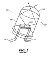
- the LED assembly 201 comprises an LED housing 203 which preferably comprises a thermally conductive material such as aluminum, copper, or various metal alloys, and which is equipped with a plurality of fins 205.
- a synthetic jet actuator 207 is disposed on said LED housing 203 and is equipped with a plurality of nozzles 209 that are adapted to direct synthetic jets into the channels formed by adjacent fins 205.
- the LED assembly 201 is shown with the synthetic jet actuator 207 being separated from the LED housing 203 by a gap, although in actual embodiments, such a gap may or may not exist.
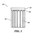
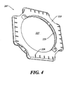
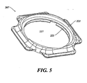
- the actuator 207 comprises a top member 221 (see FIG. 5 ) and a bottom member 223 (see FIG. 4 ) that enclose an interior space 225.
- the actuator 207 is equipped with a central opening 227 in which a diaphragm is seated (the diaphragm has been removed for ease of illustration).
- the bottom member 223 is equipped with a plurality of nozzles 229 or apertures that are arranged around the periphery of the device in four discrete sets and that are driven by the diaphragm. In use, the diaphragm is made to vibrate at a suitable frequency so as to induce the formation of synthetic jets at the nozzles.
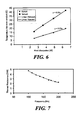
- the effectiveness of the systems described herein in cooling an LED assembly may be appreciated with reference to FIG. 6 .
- the graph shown therein illustrates the temperature rise (over ambient temperature) as a function of the quantity of heat to be dissipated.
- the data points denoted "SynJet” correspond to data obtained for an LED assembly of the type depicted in FIG. 3 which is equipped with synthetic jet actuators, while the data points denoted “Natural” correspond to the analogous system which is devoid of synthetic jet actuators.
- the temperature rise of the LED system as a function of the quantity of heat to be dissipated is essentially linear for both systems.
- the slope of the curve corresponding to the "SynJet" system is less than half of the slope of the curve for the "Natural” system (about 3.0 as compared to about 6.5).
- the LED assembly equipped with synthetic jet actuators provides a rate of heat dissipation that is about 2.2 times that of the comparative system that is not equipped with synthetic jet actuators.
- FIG. 7 illustrates the effect that the operating frequency of the synthetic jet actuator (that is, the frequency at which the diaphragm of the synthetic jet actuator vibrates) has on the ability of the device to dissipate heat.
- the operating frequency of the synthetic jet actuator that is, the frequency at which the diaphragm of the synthetic jet actuator vibrates
- thermal resistance decreases, and hence heat dissipation increases.
- the relationship between operating frequency and thermal resistance is not linear, and hence, the incremental gain in heat dissipation per unit operating frequency begins to decrease as the operating frequency increases.
- FIG. 8 is a graph of thermal resistance as a function of input (actuator) power for an LED assembly of the type depicted in FIG. 3 .
- thermal resistance decreases as input power increases.
- the relationship is not linear, and thermal resistance is found to asymptotically approach a minimum. It can thus be seen that power input can be increased to a point to achieve lower thermal resistance, but that a point of diminishing returns is reached.
- FIG. 9 illustrates the percent improvement in heat dissipation as a function of sound pressure level (SPL). As seen therein, heat dissipation improves as SPL increases and, at a weighted Sound Pressure Level of 25 dBA, the improvement in heat dissipation is about 2.5X.
- FIG. 10 illustrates the relationship between SPL and frequency. As seen therein, SPL increases with actuator frequency in an essentially linear fashion. Hence, this graph demonstrates that higher frequencies result in higher acoustic noise. In this respect, operating frequencies of 150Hz and lower are found to be optimal.
- synthetic jet actuators utilized in the LED assemblies disclosed herein, as well as in the LED assemblies themselves.
- synthetic jets may be utilized along both the interior and exterior of the housing to augment thermal management.
- the assembly 301 is equipped with a housing 303, a first set 305 of synthetic jet actuators that are disposed along, and are adapted to cool, the exterior surface of the housing 303, and a second set 307 of synthetic jet actuators that are disposed along, and are adapted to cool, the interior surface of the LED housing 303.
- Configurations of this type may optionally be used in conjunction with first and second sets of fins which are disposed, respectively, on the exterior and interior of the LED housing 303.
- first 305 and second 307 sets of synthetic jet actuators will preferably be arranged so that the synthetic jets produced are directed along the longitudinal axis of the channel formed by adjacent pairs of fins. It will also be appreciated that, while the first set 305 of synthetic jet actuators are depicted as being staggered with respect to the second set 307 of synthetic jet actuators, the first 305 and second 307 sets of synthetic jet actuators may also be arranged in an opposing fashion, or may be arranged independently of each other.
- each of the individual synthetic jet actuators in the first 305 and second 307 sets of synthetic jet actuators may be combined into a single synthetic jet actuator equipped with a plurality of nozzles that are powered by a common diaphragm, in which case the first 305 and second 307 sets of synthetic jet actuators are preferably disposed at a terminal end of the LED housing.
- each of the synthetic jet actuators may each be powered by its own diaphragm, or may be arranged into groups which are powered by a common diaphragm.
- the first set 305 of synthetic jet actuators may be powered by a first diaphragm
- the second set 307 of synthetic jet actuators may be powered by a second diaphragm.
- opposing pairs of the synthetic jet actuators may be powered off of the same diaphragm.
- some or all of the synthetic jet actuators (or nozzles associated with a single synthetic jet actuator) may be adapted to direct a synthetic jet into channels formed within the walls of the LED housing.
- FIG. 12 is a schematic diagram which illustrates an LED assembly 321 that uses an arrangement of synthetic jet actuators of the type illustrated in FIG. 11 .
- the LED assembly 321 depicted therein comprises a housing 323, an LED circuitry package 325 (which, in this embodiment, includes both the LED itself and its associated circuitry) and a synthetic jet actuator 327.
- the actuator 327 is adapted to direct a plurality of synthetic jets along the interior and exterior surfaces of the housing 323, and between the interior surface of the housing and the LED circuitry package 325.
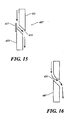
- FIG. 13 is a schematic diagram of a further embodiment of an LED assembly 341 made in accordance with the teachings herein.
- the LED assembly 341 of FIG. 13 is similar in many respects to the LED assembly depicted in FIG. 12 , but differs in that the electronics package 343 is mounted on the backside of the synthetic jet actuator 345, while the LED 347 itself is mounted on the opposing surface of the synthetic jet actuator 345.
- the synthetic jet actuator 345 is adapted to direct a flow of fluid across the surface of both the electronics package 343 and the exterior of the housing 349. In some variations of this embodiment, the synthetic jet actuator 345 may be further adapted to direct a synthetic jet along the interior surface of the housing 349.
- FIG. 14 illustrates a further embodiment of an LED assembly made in accordance with the teachings herein.
- the LED assembly 401 depicted therein comprises a synthetic jet actuator 403 upon which is mounted the LED diode 405 and the associated electronics.
- the synthetic jet actuator 403 is mounted along its periphery to the LED housing 407 and is adapted to direct a plurality of synthetic jets along the exterior of the housing.
- the LED housing 407 is equipped with a plurality of apertures 409 that allow the atmosphere inside the LED housing 407 to be in communication with the external atmosphere.
- these apertures 409 are aligned with the synthetic jets such that, while the synthetic jets cool the exterior of the housing 407, they also induce convection currents within the housing 407 that cool the diode 405.
- the synthetic jet actuator 403 may be equipped with a first set of nozzles that direct synthetic jets along the exterior surface of the LED housing 407, and a second set of nozzles that direct synthetic jets along the interior surface of the LED housing 407.
- the apertures 409 may be oriented at various angles, and in some embodiments, different sets of apertures may be oriented at different angles. The angle of the aperture may also vary in accordance with certain criteria, such as the distance of the aperture from the synthetic jet actuator 403 or a nozzle thereof.
- FIGs. 15-16 illustrate some specific configurations of apertures that may be utilized in the device depicted in FIG. 14 .
- the housing 407 contains a top portion 411 and a bottom portion 413 that are offset with respect to each other, and the aperture 415 extends at a downward angle.
- a plate 417 is provided on one side of the aperture which facilitates entrainment of the fluid flow into the aperture 415.
- the flow goes from the outside of the housing 407 to the inside of the housing, though one skilled in the art will appreciate that, in other embodiments, the fluid flow could go from the inside of the housing to the outside of the housing.
- the aperture 421 is again angled downward.
- the surface of the aperture 421 is configured as a Coanda surface. Consequently, under appropriate conditions, the fluid flow will tend to hug the surface, thus allowing the flow to be directed into the aperture 421 without the need for an offset or plate.
- FIG. 17 illustrates yet another embodiment of the LED assemblies disclosed herein.
- the LED assembly 421 depicted in FIG. 17 comprises a synthetic jet actuator 423 upon which is mounted the LED diode 425.
- the synthetic jet actuator 423 is mounted along its periphery to the LED housing 427 and is adapted to direct a plurality of synthetic jets along the exterior of the LED housing 427.
- the electronics package 429 that operates the LED diode 425 is separated therefrom, and is mounted on the exterior of the LED housing 427.
- the synthetic jet actuator 423 is preferably adapted to direct one or more synthetic jets onto the electronics package 429 to provide thermal management for the package 429.
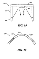
- FIG. 18 illustrates yet another embodiment of an LED assembly made in accordance with the teachings herein.
- the LED assembly 441 depicted in FIG. 16 comprises a synthetic jet actuator 443 upon which is mounted the LED diode 445.
- the synthetic jet actuator 443 is mounted along its periphery to the LED housing 447 and is adapted to direct a plurality of synthetic jets along the exterior of the LED housing 447.
- a plurality of synthetic jet actuators 449 are also mounted on the interior of the LED housing 447 and are adapted to direct a synthetic jet onto the surface of the LED diode 445.
- FIG. 17 A further variation of this embodiment is shown in FIG. 17 , where the plurality of synthetic jet actuators 449 are mounted within the LED housing 447.
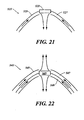
- FIGs. 20-22 illustrate some further possible configurations for directly cooling an LED diode that may be incorporated into the various examples disclosed herein.
- an LED diode 503 is provided which is embedded in the LED housing 505.
- One or more passageways 507 are provided within the LED housing 505 through which a synthetic jet may be directed to cool the LED diode 503.
- one or more channels are provided in the LED diode 503 that are in open communication with the passageway 507 in the LED housing 505, thereby permitting a direct flow of fluid through the diode 503.
- the passageways may extend around the periphery of the diode 503.
- a diode 523 is provided which is also embedded in the LED housing 525, and the LED housing 525 is again provided with one or more passageways 527 for the flow of a fluid therethrough.
- the passageways are in open communication with the interior of the LED housing 525 in the vicinity of the diode 523. Consequently, the flow of a synthetic jet through the passageways creates a flow of fluid over the active surface of the diode 523.
- a diode 543 is provided which is also embedded in the LED housing 545.
- the LED housing 545 is provided with first 547 and second 549 passageways for the flow of a fluid therethrough, with the first passageway 547 being in open communication with the exterior of the LED housing 545 in the vicinity of the diode 543, and the second passageway 549 being in open communication with the interior of the LED housing 545 in the vicinity of the diode 543. Consequently, when these passageways are connected to a synthetic jet actuator, the jet traverses the passageways and creates a flow of fluid over both surfaces of the diode 543.
- a single passageway may be provided that is in open communication with both the interior and exterior of the LED housing 545.
- one or more additional heat sinks may also be attached to one or more surfaces of the LED module.
- an external heat sink may be attached to the bottom of the LED assembly.
- These heat sinks may be conventional heat sinks, or they may be heat sinks that utilize synthetic jet actuators.
- acoustical or electromagnetic synthetic jet actuators is preferred in the various embodiments and examples disclosed herein, other types of actuators may also be used. These include, without limitation, piezoelectric actuators and reed jet actuators.
- the synthetic jet actuators described herein may be equipped with various drive mechanisms.
- the electronics for the drive mechanisms of the synthetic jet actuators is integrated with the electronics for the LED assembly.
- the LED cavity may be utilized as all or part of the cavity of an acoustic resonator, such as a Helmholtz resonator or pipe resonator.
- an acoustic resonator such as a Helmholtz resonator or pipe resonator.
- Such embodiments may, in some applications, provide especially high energy efficiencies.
- Resonators of this type are described ion commonly assigned US Patent Application No. 2007/081027 by Beltran et al. , entitled “Acoustic Resonator for Synthetic Jet Generation for Thermal Management", and filed on October 12, 2005.
- LED assemblies may also be made in accordance with the teachings herein which serve as multi-directional light sources.
- One example is the dual-sided LED assembly 601 shown in FIG. 23 .
- the assembly 601 depicted therein includes a housing 603 equipped with first 605 and second 607 opposing apertures, and an LED 609 which is disposed in the central cavity of the housing 603.
- the housing 603 is further equipped on each terminal portion with an annular magnet 611, a coil 613, a surround 615, and an annular diaphragm 617.
- the LED 609 emits light through the central cavity of the housing 603, while synthetic jets are produced from either a central orifice or peripheral orifices through vibration of the diaphragm 617, resulting in a rapid mixing and ejection of flow from within the central cavity as indicated by the arrows.
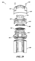
- FIGs. 25-42 depict a further particular example of an LED assembly in accordance with the teachings herein which does not form part of the invention.
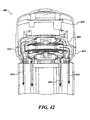
- the LED assembly 801 depicted therein comprises a synthetic jet actuator 803 having a heat sink 805 disposed on one end thereof, and having a control portion 807 disposed on the opposing end.
- the synthetic jet actuator 803 comprises first 809 and second 811 actuator elements which are arranged in opposing relation to each other and which are disposed within upper 813 and lower 815 housing elements.
- the first 809 and second 811 actuator elements are seated on a flow divider 817 which serves to direct synthetic jets emitted from the synthetic jet actuator 803 over the surfaces of the heat sink 805 (see FIG. 42 ).
- the flow divider 817 contains a plurality of protrusions 818 (see FIGs.
- first 809 and second 811 actuator elements may be replaced by a single actuator element.
- the use of two or more actuator elements is advantageous in some implementations for reducing the audio and vibrational footprint of the synthetic jet actuator 803.
- the control portion 807 of the LED assembly 801 comprises a cover 819 which is secured to the upper housing element 813 with one or more suitable fasteners 821, and which houses the control circuitry 823 that controls the operation of the synthetic jet actuator 803.
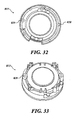
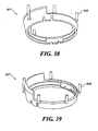
- the upper housing element 813 is further equipped with an annular surface 825 which is complimentary in shape to the interior surface of the cover 811, and which terminates in a lip 827 (see FIG. 30 ). This arrangement allows the cover 819 to be firmly seated on the upper housing element 813.
- the fasteners 821 are threaded screws which rotatingly engage the complimentary threads of opposing receptacles 829 (see FIGs. 32-33 ) disposed on the exterior surface of the upper housing element 813.
- the cover 819 may be equipped with a threaded lip which rotatingly engages a set of complimentary shaped threads defined on a surface of the upper housing element 813.
- the cover 819 may be secured to the upper housing element 813 with a suitable adhesive, which may be applied, for example, to the annular surface 825 of the upper housing element 813 and/or to the corresponding surface of the cover 819.
- the cover 819 preferably comprises a suitable molded plastic, but may comprise various other materials, including, but not limited to, various metals and glasses. As seen, for example, in FIG. 26 , the cover 819 is equipped with a first set of apertures 831 to accommodate the fasteners 821, and is equipped with a second set of apertures 833 to permit cooling of the control circuitry 823 (see FIG. 27 ) through convection. In some embodiments, thermal management of the control circuitry 823 may be implemented or supplemented by causing one or more synthetic jets emitted from the synthetic jet actuator 803 to impinge upon the control circuitry 823 or on portions thereof.
- control circuitry 823 is disposed on a single printed circuit board (PCB), although in various embodiments, this circuitry may be disposed over multiple PCBs or die.
- the control circuitry 823 is adapted to control the functioning of the synthetic jet ejector, including, for example, the operating frequencies at which the first 809 and second 811 actuator elements operate.
- the control circuitry 823 may be adapted to control the frequencies at which the first 809 and second 811 actuator elements operate with respect to each other so as to optimize thermal management and/or minimize the acoustical and/or audio footprint of the synthetic jet actuator 803.
- the control circuitry 823 may be adapted to implement various mathematical algorithms in this regard.
- the heat sink 805 is generally annular in shape and contains an LED mounting surface 835 (see FIG. 41 ) on one end thereof.
- the LED package 837 which includes the LED and any associated circuitry, is mounted on this surface within the annulus of the heat sink 805.
- the LED package 837 may instead be disposed in other regions of the device.
- the LED package 837 may be integrated, in part or in whole, with the control circuitry 823.
- the LED assembly 801 may be adapted such that one or more synthetic jets are impinged on the LED package 837 or portions thereof.
- the heat sink 805 may also be moved in such examples so that it is in closer proximity to the LED package 837, or else a flow path may be designed such that hot air is directed from the LED package 837 to the heat sink 805.
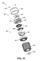
- FIG. 42 illustrates the flow paths for synthetic jets in the particular example of the LED assembly 801 depicted.
- the upper housing element 813, the lower housing element 815 and the flow divider 817 upon proper assembly, define a plurality of flow paths through the device.
- a first set of flow paths 851 originate from the top surface of the upper actuator element 809 and terminate along the external fins of the heat sink 805.
- a second set of flow paths 853 originate between the upper actuator element 809 and the lower actuator element 811 and terminate along the external fins of the heat sink 805.
- a third set of flow paths 855 originate from the bottom surface of the lower actuator element 811 and terminate along the inside surface of the heat sink 805.
- the third set of flow paths 855 includes a first plurality of holes 857 (see FIG.
- the first 851 and second 853 sets of flow paths include a third plurality of holes 860 defined along the periphery of the lower housing element 815.
- the first 857 and second 859 plurality of holes are held in alignment by a plurality of posts 861 (SEE fig. 40 ) defined on the upper surface of the heat sink 805 which engage a set of complimentary shaped apertures 863 defined in the bottom housing element 815, and which serve the additional purpose of securing the heat sink 805 to the bottom housing element 815.
- a portion of suitable adhesive may be applied to these posts and/or to the opposing surfaces of the heat sink 805 and the lower housing element 815 to further secure these elements together.
- the posts 861 and apertures 863 likewise align the third plurality of holes 860 with the spaces defined by adjacent fins in the heat sink 805.
- various other means may be used to secure these elements together and to key or register the holes into proper alignment with each other so as to achieve and maintain proper flow paths.
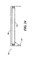
- FIG. 24 illustrates a fluorescent light fixture 701.
- the fixture 701 comprises a fluorescent bulb 703 which is mounted within a housing 705.
- a synthetic jet actuator 707 is mounted on an interior wall of the housing 705 and is adapted to direct a synthetic jet at the hotspot generated along the length of the bulb 703. It has been found that, by thermally managing the hotspot, the life of the fluorescent bulb is significantly increased.
- the fluid utilized by the synthetic jet actuator to provide thermal management is preferably air.
- gases or liquids may be utilized as the fluid.
- the use of inert gasses such as nitrogen, argon, helium, or fluorocarbons may be advantageous.
- ambient air may be utilized as the fluid medium, but filters or scrubbers may be provided to remove certain components of the air.
- the LED assembly may be equipped with a desiccant to control the moisture content of air entering the assembly.
- liquids may be employed as the fluid medium.
- Such liquids include, but are not limited to, water and various organic liquids, such as, for example, polyethylene glycol, polypropylene glycol, and other polyols, partially fluorinated or perfluorinated ethers, and various dielectric materials.
- Liquid metals (which are generally metal alloys with an amorphous atomic structure) may also be advantageously used in some embodiments and examples of the devices and methodologies described herein.
- the actuators may be energized at an audible frequency or sweep of frequencies in response to detection of a certain operating or environmental state.
- the synthetic jet actuators may be configured to operate as a siren or alarm in order to alert the user of an illumination device to a performance change (e.g., that it is time to replace the LED or that a color component is malfunctioning) or an emergency state (e.g., the detection of smoke or an intruder).
- a performance change e.g., that it is time to replace the LED or that a color component is malfunctioning
- an emergency state e.g., the detection of smoke or an intruder.
- a similar approach could be used to create illumination devices that serve various other functionalities, such as alarm clock functions. Typically, these additional functionalities will require little or no additional hardware, although some added functionality to the actuator driver may be required.
Landscapes
- Engineering & Computer Science (AREA)
- Microelectronics & Electronic Packaging (AREA)
- General Engineering & Computer Science (AREA)
- Physics & Mathematics (AREA)
- Thermal Sciences (AREA)
- Manufacturing & Machinery (AREA)
- Computer Hardware Design (AREA)
- Power Engineering (AREA)
- Non-Portable Lighting Devices Or Systems Thereof (AREA)
- Arrangement Of Elements, Cooling, Sealing, Or The Like Of Lighting Devices (AREA)
- Led Device Packages (AREA)
Claims (3)
- LED-Anordnung (401), die aufweist:ein Gehäuse (407);eine LED (405), die in dem Gehäuse angeordnet ist; undeinen Aktuator (403) für einen synthetischen Strahl, der dazu ausgelegt ist, einen synthetischen Strahl auf die oder entlang der LED zu richten;dadurch gekennzeichnet, dassder Aktuator (403) für einen synthetischen Strahl an einem Anschlussabschnitt des LED-Gehäuses (407) angeordnet ist, wobei die LED (405) auf einer ersten Oberfläche des Aktuators (403) angeordnet ist.
- LED-Anordnung nach Anspruch 1, wobei das Gehäuse (407) mit einem Durchlass (409; 415; 421) ausgestattet ist und wobei der Aktuator (403) für einen synthetischen Strahl dazu ausgelegt ist, einen synthetischen Strahl durch die Öffnung des Durchlasses zu richten.
- LED-Anordnung nach Anspruch 2, wobei der Durchlass (409; 415; 421) von der Richtung des synthetischen Strahls, der durch die Öffnung des Durchlasses gerichtet wird, weg geneigt ist.
Applications Claiming Priority (2)
| Application Number | Priority Date | Filing Date | Title |
|---|---|---|---|
| US11/265,778 US7932535B2 (en) | 2005-11-02 | 2005-11-02 | Synthetic jet cooling system for LED module |
| PCT/US2006/043081 WO2007056209A2 (en) | 2005-11-02 | 2006-11-02 | Synthetic jet cooling system for led module |
Publications (3)
| Publication Number | Publication Date |
|---|---|
| EP1943687A2 EP1943687A2 (de) | 2008-07-16 |
| EP1943687A4 EP1943687A4 (de) | 2012-08-08 |
| EP1943687B1 true EP1943687B1 (de) | 2014-01-22 |
Family
ID=37995079
Family Applications (1)
| Application Number | Title | Priority Date | Filing Date |
|---|---|---|---|
| EP06836931.3A Ceased EP1943687B1 (de) | 2005-11-02 | 2006-11-02 | Synthesestrahl-kühlsystem für ein led-modul |
Country Status (4)
| Country | Link |
|---|---|
| US (1) | US7932535B2 (de) |
| EP (1) | EP1943687B1 (de) |
| JP (1) | JP2009515342A (de) |
| WO (1) | WO2007056209A2 (de) |
Families Citing this family (79)
| Publication number | Priority date | Publication date | Assignee | Title |
|---|---|---|---|---|
| US10340424B2 (en) | 2002-08-30 | 2019-07-02 | GE Lighting Solutions, LLC | Light emitting diode component |
| US8968221B2 (en) * | 2007-04-17 | 2015-03-03 | Bwt Property, Inc. | Apparatus and methods for phototherapy |
| US8058802B2 (en) | 2007-09-28 | 2011-11-15 | General Electric Company | Thermal management article and method |
| US7898176B2 (en) * | 2007-09-28 | 2011-03-01 | General Electric Company | Fluidic thermal management article and method |
| US7742673B2 (en) | 2007-09-28 | 2010-06-22 | General Electric Company | Thermal mangement article having thermal wave guide |
| US20090084866A1 (en) * | 2007-10-01 | 2009-04-02 | Nuventix Inc. | Vibration balanced synthetic jet ejector |
| US8066410B2 (en) * | 2007-10-24 | 2011-11-29 | Nuventix, Inc. | Light fixture with multiple LEDs and synthetic jet thermal management system |
| US8845138B2 (en) | 2007-10-24 | 2014-09-30 | Nuventix, Inc. | Light fixture with multiple LEDs and synthetic jet thermal management system |
| WO2009061454A1 (en) * | 2007-11-06 | 2009-05-14 | Nuventix, Inc. | Method and apparatus for controlling diaphragm displacement in synthetic jet actuators |
| US9726201B2 (en) * | 2007-12-07 | 2017-08-08 | Philips Lighting Holding B.V. | Cooling device utilizing internal synthetic jets |
| WO2009137696A1 (en) * | 2008-05-08 | 2009-11-12 | Express Imaging Systems, Llc | Low-profile pathway illumination system |
| WO2009140141A1 (en) * | 2008-05-13 | 2009-11-19 | Express Imaging Systems, Llc | Gas-discharge lamp replacement |
| US8882685B2 (en) * | 2008-05-27 | 2014-11-11 | Bwt Property, Inc. | Apparatus and methods for phototherapy |
| US8212469B2 (en) | 2010-02-01 | 2012-07-03 | Abl Ip Holding Llc | Lamp using solid state source and doped semiconductor nanophosphor |
| US8021008B2 (en) * | 2008-05-27 | 2011-09-20 | Abl Ip Holding Llc | Solid state lighting using quantum dots in a liquid |
| WO2010004469A1 (en) * | 2008-07-10 | 2010-01-14 | Philips Intellectual Property & Standards Gmbh | Remote cooling by combining heat pipe and resonator for synthetic jet cooling |
| US8777456B2 (en) | 2008-07-15 | 2014-07-15 | Nuventix, Inc. | Thermal management of LED-based illumination devices with synthetic jet ejectors |
| US8334640B2 (en) * | 2008-08-13 | 2012-12-18 | Express Imaging Systems, Llc | Turbulent flow cooling for electronic ballast |
| JP5852442B2 (ja) * | 2008-11-17 | 2016-02-03 | エクスプレス イメージング システムズ,エルエルシーExpress Imaging Systems,Llc | 固体照明用電源を調整するための電子制御装置とその方法 |
| US8240885B2 (en) * | 2008-11-18 | 2012-08-14 | Abl Ip Holding Llc | Thermal management of LED lighting systems |
| US8926139B2 (en) * | 2009-05-01 | 2015-01-06 | Express Imaging Systems, Llc | Gas-discharge lamp replacement with passive cooling |
| US8508137B2 (en) * | 2009-05-20 | 2013-08-13 | Express Imaging Systems, Llc | Apparatus and method of energy efficient illumination |
| US8872964B2 (en) * | 2009-05-20 | 2014-10-28 | Express Imaging Systems, Llc | Long-range motion detection for illumination control |
| US20110026264A1 (en) * | 2009-07-29 | 2011-02-03 | Reed William G | Electrically isolated heat sink for solid-state light |
| US20120186271A1 (en) * | 2009-09-29 | 2012-07-26 | Koninklijke Philips Electronics N.V. | Noise reduction for an acoustic cooling system |
| US8593040B2 (en) | 2009-10-02 | 2013-11-26 | Ge Lighting Solutions Llc | LED lamp with surface area enhancing fins |
| US20110144725A1 (en) | 2009-12-11 | 2011-06-16 | Bwt Property, Inc. | Phototherapy Apparatus With Interactive User Interface |
| US8695686B2 (en) | 2010-01-07 | 2014-04-15 | General Electric Company | Method and apparatus for removing heat from electronic devices using synthetic jets |
| US9719012B2 (en) * | 2010-02-01 | 2017-08-01 | Abl Ip Holding Llc | Tubular lighting products using solid state source and semiconductor nanophosphor, E.G. for florescent tube replacement |
| WO2011100645A1 (en) | 2010-02-13 | 2011-08-18 | Nuventix, Inc. | Synthetic jet ejector and design thereof to facilitate mass production |
| US8517550B2 (en) | 2010-02-15 | 2013-08-27 | Abl Ip Holding Llc | Phosphor-centric control of color of light |
| US8434906B2 (en) * | 2010-02-23 | 2013-05-07 | General Electric Company | Lighting system with thermal management system |
| US9241401B2 (en) | 2010-06-22 | 2016-01-19 | Express Imaging Systems, Llc | Solid state lighting device and method employing heat exchanger thermally coupled circuit board |
| US8506105B2 (en) | 2010-08-25 | 2013-08-13 | Generla Electric Company | Thermal management systems for solid state lighting and other electronic systems |
| US9523367B2 (en) | 2010-08-25 | 2016-12-20 | Aavid Thermalloy, Llc | Cantilever fan |
| US8602607B2 (en) * | 2010-10-21 | 2013-12-10 | General Electric Company | Lighting system with thermal management system having point contact synthetic jets |
| US8529097B2 (en) | 2010-10-21 | 2013-09-10 | General Electric Company | Lighting system with heat distribution face plate |
| US8901825B2 (en) | 2011-04-12 | 2014-12-02 | Express Imaging Systems, Llc | Apparatus and method of energy efficient illumination using received signals |
| KR101227522B1 (ko) * | 2011-05-25 | 2013-01-31 | 엘지전자 주식회사 | 조명 장치 |
| US8610358B2 (en) | 2011-08-17 | 2013-12-17 | Express Imaging Systems, Llc | Electrostatic discharge protection for luminaire |
| EP2749145B1 (de) | 2011-08-24 | 2017-11-15 | Express Imaging Systems, LLC | Resonantes netzwerk zur reduzierung von flimmerwahrnehmung in festkörperbeleuchtungssystemen |
| CN103090338B (zh) * | 2011-11-03 | 2018-10-09 | 欧司朗股份有限公司 | 驱动器组件及其制造方法 |
| US8922124B2 (en) | 2011-11-18 | 2014-12-30 | Express Imaging Systems, Llc | Adjustable output solid-state lamp with security features |
| US9360198B2 (en) | 2011-12-06 | 2016-06-07 | Express Imaging Systems, Llc | Adjustable output solid-state lighting device |
| US9497393B2 (en) | 2012-03-02 | 2016-11-15 | Express Imaging Systems, Llc | Systems and methods that employ object recognition |
| US9210751B2 (en) | 2012-05-01 | 2015-12-08 | Express Imaging Systems, Llc | Solid state lighting, drive circuit and method of driving same |
| US9204523B2 (en) | 2012-05-02 | 2015-12-01 | Express Imaging Systems, Llc | Remotely adjustable solid-state lamp |
| US9587820B2 (en) | 2012-05-04 | 2017-03-07 | GE Lighting Solutions, LLC | Active cooling device |
| US9500355B2 (en) | 2012-05-04 | 2016-11-22 | GE Lighting Solutions, LLC | Lamp with light emitting elements surrounding active cooling device |
| TWI475180B (zh) | 2012-05-31 | 2015-03-01 | Ind Tech Res Inst | 合成噴流裝置 |
| US9194575B2 (en) | 2012-06-29 | 2015-11-24 | General Electric Company | Thermal management in optical and electronic devices |
| US9131552B2 (en) | 2012-07-25 | 2015-09-08 | Express Imaging Systems, Llc | Apparatus and method of operating a luminaire |
| US8878440B2 (en) | 2012-08-28 | 2014-11-04 | Express Imaging Systems, Llc | Luminaire with atmospheric electrical activity detection and visual alert capabilities |
| US8896215B2 (en) | 2012-09-05 | 2014-11-25 | Express Imaging Systems, Llc | Apparatus and method for schedule based operation of a luminaire |
| US9301365B2 (en) | 2012-11-07 | 2016-03-29 | Express Imaging Systems, Llc | Luminaire with switch-mode converter power monitoring |
| US9210759B2 (en) | 2012-11-19 | 2015-12-08 | Express Imaging Systems, Llc | Luminaire with ambient sensing and autonomous control capabilities |
| US9288873B2 (en) | 2013-02-13 | 2016-03-15 | Express Imaging Systems, Llc | Systems, methods, and apparatuses for using a high current switching device as a logic level sensor |
| US9184109B2 (en) | 2013-03-01 | 2015-11-10 | Nuventix, Inc. | Synthetic jet actuator equipped with entrainment features |
| US9466443B2 (en) | 2013-07-24 | 2016-10-11 | Express Imaging Systems, Llc | Photocontrol for luminaire consumes very low power |
| US9414449B2 (en) | 2013-11-18 | 2016-08-09 | Express Imaging Systems, Llc | High efficiency power controller for luminaire |
| WO2015116812A1 (en) | 2014-01-30 | 2015-08-06 | Express Imaging Systems, Llc | Ambient light control in solid state lamps and luminaires |
| WO2016054085A1 (en) | 2014-09-30 | 2016-04-07 | Express Imaging Systems, Llc | Centralized control of area lighting hours of illumination |
| WO2016064542A1 (en) | 2014-10-24 | 2016-04-28 | Express Imaging Systems, Llc | Detection and correction of faulty photo controls in outdoor luminaires |
| US9462662B1 (en) | 2015-03-24 | 2016-10-04 | Express Imaging Systems, Llc | Low power photocontrol for luminaire |
| US9538612B1 (en) | 2015-09-03 | 2017-01-03 | Express Imaging Systems, Llc | Low power photocontrol for luminaire |
| EP3153771B1 (de) * | 2015-10-05 | 2018-06-13 | Vestel Elektronik Sanayi ve Ticaret A.S. | Kühlvorrichtung und verfahren zur kühlung einer leuchtmodul |
| US9924582B2 (en) | 2016-04-26 | 2018-03-20 | Express Imaging Systems, Llc | Luminaire dimming module uses 3 contact NEMA photocontrol socket |
| US9985429B2 (en) | 2016-09-21 | 2018-05-29 | Express Imaging Systems, Llc | Inrush current limiter circuit |
| US10230296B2 (en) | 2016-09-21 | 2019-03-12 | Express Imaging Systems, Llc | Output ripple reduction for power converters |
| US10098212B2 (en) | 2017-02-14 | 2018-10-09 | Express Imaging Systems, Llc | Systems and methods for controlling outdoor luminaire wireless network using smart appliance |
| US10568191B2 (en) | 2017-04-03 | 2020-02-18 | Express Imaging Systems, Llc | Systems and methods for outdoor luminaire wireless control |
| US10219360B2 (en) | 2017-04-03 | 2019-02-26 | Express Imaging Systems, Llc | Systems and methods for outdoor luminaire wireless control |
| US11375599B2 (en) | 2017-04-03 | 2022-06-28 | Express Imaging Systems, Llc | Systems and methods for outdoor luminaire wireless control |
| US10904992B2 (en) | 2017-04-03 | 2021-01-26 | Express Imaging Systems, Llc | Systems and methods for outdoor luminaire wireless control |
| US10164374B1 (en) | 2017-10-31 | 2018-12-25 | Express Imaging Systems, Llc | Receptacle sockets for twist-lock connectors |
| US11234304B2 (en) | 2019-05-24 | 2022-01-25 | Express Imaging Systems, Llc | Photocontroller to control operation of a luminaire having a dimming line |
| US11317497B2 (en) | 2019-06-20 | 2022-04-26 | Express Imaging Systems, Llc | Photocontroller and/or lamp with photocontrols to control operation of lamp |
| US11212887B2 (en) | 2019-11-04 | 2021-12-28 | Express Imaging Systems, Llc | Light having selectively adjustable sets of solid state light sources, circuit and method of operation thereof, to provide variable output characteristics |
| PL440936A1 (pl) * | 2022-04-13 | 2023-10-16 | Politechnika Rzeszowska im. Ignacego Łukasiewicza | Generator strugi syntetycznej zasilany silnikiem elektrycznym |
Family Cites Families (98)
| Publication number | Priority date | Publication date | Assignee | Title |
|---|---|---|---|---|
| US3464672A (en) * | 1966-10-26 | 1969-09-02 | Dynamics Corp America | Sonic processing transducer |
| US4031171A (en) * | 1974-12-25 | 1977-06-21 | Mikuni Kogyo Kabushiki Kaisha | Ultrasonic air humidifying apparatus |
| IL52613A (en) * | 1977-07-28 | 1980-11-30 | Univ Ramot | Method and apparatus for controlling the mixing of two fluids |
| JPS5550437U (de) * | 1978-09-28 | 1980-04-02 | ||
| US4501319A (en) * | 1979-04-17 | 1985-02-26 | The United States Of America As Represented By The Secretary Of The Army | Piezoelectric polymer heat exchanger |
| US4498851A (en) * | 1980-05-02 | 1985-02-12 | Piezo Electric Products, Inc. | Solid state blower |
| US4941398A (en) * | 1981-06-03 | 1990-07-17 | Bowles Fluidics Corporation | Oscillating reed and method |
| JPS57202056A (en) * | 1981-06-05 | 1982-12-10 | Toshiba Corp | Fluorescent lamp unit |
| JPS58119217A (ja) * | 1982-01-07 | 1983-07-15 | Murata Mfg Co Ltd | 圧電音叉 |
| US4406323A (en) * | 1982-01-25 | 1983-09-27 | Seymour Edelman | Piezoelectric heat exchanger |
| US4490649A (en) * | 1982-10-20 | 1984-12-25 | General Electric Company | Thermal baffle inside a discharge lamp |
| US4590970A (en) * | 1983-09-22 | 1986-05-27 | Honeywell Inc. | Pulse width modulated pressure source |
| US4595338A (en) * | 1983-11-17 | 1986-06-17 | Piezo Electric Products, Inc. | Non-vibrational oscillating blade piezoelectric blower |
| DE3342421C2 (de) * | 1983-11-24 | 1987-01-29 | Messerschmitt-Bölkow-Blohm GmbH, 8012 Ottobrunn | Verfahren zur stabilisierenden Beeinflussung abgelöster laminarer Grenzschichten |
| US4590399A (en) * | 1984-02-28 | 1986-05-20 | Exxon Research And Engineering Co. | Superlattice piezoelectric devices |
| JPH071374B2 (ja) * | 1984-03-06 | 1995-01-11 | 株式会社ニコン | 光源装置 |
| US4697769A (en) * | 1984-04-23 | 1987-10-06 | Flow Industries, Inc. | Method and apparatus for controlling bound vortices in the vicinity of lifting surfaces |
| US4667877A (en) * | 1985-08-15 | 1987-05-26 | Carnegie-Mellon University | Multi-orifice impulsed spray generator |
| EP0213426A1 (de) * | 1985-08-30 | 1987-03-11 | Siemens Aktiengesellschaft | Gehäuse mit Bodenwanne und Aussendeckel für ein elektrisches Schaltungsbauteil |
| US4780062A (en) * | 1985-10-09 | 1988-10-25 | Murata Manufacturing Co., Ltd. | Piezoelectric fan |
| US5089862A (en) * | 1986-05-12 | 1992-02-18 | Warner Jr Raymond M | Monocrystalline three-dimensional integrated circuit |
| US4708600A (en) * | 1986-02-24 | 1987-11-24 | Abujudom Ii David N | Piezoelectric fluid pumping apparatus |
| US4932610A (en) * | 1986-03-11 | 1990-06-12 | The United States Of America As Represented By The United States National Aeronautics And Space Administration | Active control of boundary layer transition and turbulence |
| US4802642A (en) * | 1986-10-14 | 1989-02-07 | The Boeing Company | Control of laminar flow in fluids by means of acoustic energy |
| US4930701A (en) * | 1987-09-08 | 1990-06-05 | Mcdonnell Douglas Corporation | Confluent nozzle |
| DE3738366A1 (de) * | 1987-11-12 | 1989-05-24 | Deutsche Forsch Luft Raumfahrt | Verfahren und vorrichtung zur erzeugung eines laminar-turbulenten grenzschichtuebergangs bei umstroemten koerpern |
| JPH01174278A (ja) * | 1987-12-28 | 1989-07-10 | Misuzu Erii:Kk | インバータ |
| US5008582A (en) * | 1988-01-29 | 1991-04-16 | Kabushiki Kaisha Toshiba | Electronic device having a cooling element |
| US4938742A (en) * | 1988-02-04 | 1990-07-03 | Smits Johannes G | Piezoelectric micropump with microvalves |
| US5209438A (en) * | 1988-06-20 | 1993-05-11 | Israel Wygnanski | Method and apparatus for delaying the separation of flow from a solid surface |
| US4976311A (en) * | 1988-11-18 | 1990-12-11 | University Of Florida | Heat exchanger employing fluid oscillation |
| US4923000A (en) | 1989-03-03 | 1990-05-08 | Microelectronics And Computer Technology Corporation | Heat exchanger having piezoelectric fan means |
| US4969802A (en) * | 1989-12-27 | 1990-11-13 | United States Department Of Energy | Vibratory pumping of a free fluid stream |
| US5083194A (en) * | 1990-01-16 | 1992-01-21 | Cray Research, Inc. | Air jet impingement on miniature pin-fin heat sinks for cooling electronic components |
| CN1055446A (zh) * | 1990-04-06 | 1991-10-16 | 菲利浦光灯制造公司 | 无电极低压放电灯 |
| US5190099A (en) * | 1991-05-01 | 1993-03-02 | The United States Of The America As Represented By The Secretary Of The Army | Pulsatile impinging cooling system for electronic IC modules and systems using fluidic oscillators |
| CA2044886C (en) * | 1991-06-18 | 1995-07-04 | Hsiang Ta Cheng | Projective lamp |
| JPH05102688A (ja) * | 1991-06-21 | 1993-04-23 | Toshiba Corp | 電子機器装置 |
| US6008126A (en) * | 1992-04-08 | 1999-12-28 | Elm Technology Corporation | Membrane dielectric isolation IC fabrication |
| US5437421A (en) * | 1992-06-26 | 1995-08-01 | British Technology Group Usa, Inc. | Multiple electromagnetic tiles for boundary layer control |
| FR2694215B1 (fr) * | 1992-07-30 | 1994-10-21 | Dp Medical | Appareil pour générer un brouillard à partir d'un liquide, notamment un médicament. |
| SE501139C2 (sv) * | 1993-04-08 | 1994-11-21 | Sem Ab | Anordning vid fluidpump av membrantyp |
| DK48993D0 (da) * | 1993-04-30 | 1993-04-30 | Steen Erik Holm | Forstoevningsapparat til vandbaaret lungemedicin |
| US5429302A (en) * | 1993-05-19 | 1995-07-04 | Fisons Corporation | Nebulizing element and device |
| US5493615A (en) * | 1993-05-26 | 1996-02-20 | Noise Cancellation Technologies | Piezoelectric driven flow modulator |
| US5346745A (en) * | 1993-06-01 | 1994-09-13 | The United States Of America As Represented By The Secretary Of The Navy | Elastic micro-fabricated surface layer for reducing turbulence and drag on an object while it moves through a fluid medium |
| US5335143A (en) * | 1993-08-05 | 1994-08-02 | International Business Machines Corporation | Disk augmented heat transfer system |
| US5395592A (en) * | 1993-10-04 | 1995-03-07 | Bolleman; Brent | Acoustic liquid processing device |
| CA2112093C (en) * | 1993-12-21 | 1995-02-21 | John A. Burgener | Parallel path induction nebulizer |
| US5419780A (en) * | 1994-04-29 | 1995-05-30 | Ast Research, Inc. | Method and apparatus for recovering power from semiconductor circuit using thermoelectric device |
| CA2150628A1 (en) * | 1994-06-02 | 1995-12-03 | Lawrence Sirovich | Method of and apparatus for controlling turbulence in boundary layer and other wall-bounded fluid flow fields |
| CA2169230A1 (en) * | 1995-02-13 | 1996-08-14 | Lawrence Sirovich | Method of and apparatus for controlling turbulence in boundary layer and other wall-bounded fluid flow fields |
| US5876187A (en) * | 1995-03-09 | 1999-03-02 | University Of Washington | Micropumps with fixed valves |
| DE59510549D1 (de) * | 1995-03-14 | 2003-03-13 | Sulzer Markets & Technology Ag | Verfahren zum aktiven Dämpfen globaler Strömungsoszillationen in abgelösten instabilen Strömungen und Vorrichtung zur Anwendung des Verfahrens |
| US6020257A (en) * | 1995-06-07 | 2000-02-01 | Elm Technology Corporation | Membrane dielectric isolation IC fabrication |
| US6123145A (en) * | 1995-06-12 | 2000-09-26 | Georgia Tech Research Corporation | Synthetic jet actuators for cooling heated bodies and environments |
| US6457654B1 (en) * | 1995-06-12 | 2002-10-01 | Georgia Tech Research Corporation | Micromachined synthetic jet actuators and applications thereof |
| US5758823A (en) * | 1995-06-12 | 1998-06-02 | Georgia Tech Research Corporation | Synthetic jet actuator and applications thereof |
| DE69637458T2 (de) * | 1995-08-07 | 2009-03-05 | Omron Healthcare Co., Ltd. | Zerstäubungsvorrichtung und Verfahren die akustische Oberflächenwellen anwenden |
| US5791601A (en) * | 1995-08-22 | 1998-08-11 | Dancila; D. Stefan | Apparatus and method for aerodynamic blowing control using smart materials |
| JPH09321360A (ja) * | 1996-05-27 | 1997-12-12 | Honda Motor Co Ltd | 圧電ファン |
| US5785418A (en) * | 1996-06-27 | 1998-07-28 | Hochstein; Peter A. | Thermally protected LED array |
| US6045240A (en) * | 1996-06-27 | 2000-04-04 | Relume Corporation | LED lamp assembly with means to conduct heat away from the LEDS |
| DE59700650D1 (de) * | 1996-08-23 | 1999-12-09 | Asea Brown Boveri | Gehäuse mit einer Belüftungsvorrichtung für ein elektronisches Gerät |
| DE19802367C1 (de) * | 1997-02-19 | 1999-09-23 | Hahn Schickard Ges | Mikrodosiervorrichtungsarray und Verfahren zum Betreiben desselben |
| US5861703A (en) * | 1997-05-30 | 1999-01-19 | Motorola Inc. | Low-profile axial-flow single-blade piezoelectric fan |
| US5901037A (en) * | 1997-06-18 | 1999-05-04 | Northrop Grumman Corporation | Closed loop liquid cooling for semiconductor RF amplifier modules |
| US5983944A (en) * | 1998-03-20 | 1999-11-16 | Niv; Shaul E. | Apparatus for active fluid control |
| JP3154329B2 (ja) * | 1998-07-21 | 2001-04-09 | 川崎重工業株式会社 | アキシャルピストンポンプ |
| US6353295B1 (en) * | 1999-01-20 | 2002-03-05 | Philips Electronics North America Corporation | Lamp electronic ballast with a piezoelectric cooling fan |
| US6517221B1 (en) * | 1999-06-18 | 2003-02-11 | Ciena Corporation | Heat pipe heat sink for cooling a laser diode |
| US6554607B1 (en) * | 1999-09-01 | 2003-04-29 | Georgia Tech Research Corporation | Combustion-driven jet actuator |
| JP3814132B2 (ja) * | 1999-10-27 | 2006-08-23 | セイコーインスツル株式会社 | ポンプ及びその駆動方法 |
| US6318886B1 (en) * | 2000-02-11 | 2001-11-20 | Whelen Engineering Company | High flux led assembly |
| US6440212B1 (en) * | 2000-02-28 | 2002-08-27 | Microfab Technologies, Inc. | Low cost method for making thermoelectric coolers |
| US6517218B2 (en) * | 2000-03-31 | 2003-02-11 | Relume Corporation | LED integrated heat sink |
| US6451175B1 (en) * | 2000-08-15 | 2002-09-17 | Wisconsin Alumni Research Foundation | Method and apparatus for carbon nanotube production |
| DE20015931U1 (de) * | 2000-09-14 | 2001-01-04 | Lin, Liken, Tu-Cheng, Taipeh | CPU-Kühlvorrichtung |
| US20020098097A1 (en) * | 2001-01-22 | 2002-07-25 | Angad Singh | Magnetically-actuated micropump |
| US6541800B2 (en) * | 2001-02-22 | 2003-04-01 | Weldon Technologies, Inc. | High power LED |
| US6628522B2 (en) * | 2001-08-29 | 2003-09-30 | Intel Corporation | Thermal performance enhancement of heat sinks using active surface features for boundary layer manipulations |
| US6511209B1 (en) * | 2001-10-02 | 2003-01-28 | Albert C. L. Chiang | Lighting fixture |
| US6650048B2 (en) * | 2001-10-19 | 2003-11-18 | Jiahn-Chang Wu | Ventilated light emitting diode matrix panel |
| US6722581B2 (en) * | 2001-10-24 | 2004-04-20 | General Electric Company | Synthetic jet actuators |
| JP4055405B2 (ja) * | 2001-12-03 | 2008-03-05 | ソニー株式会社 | 電子部品及びその製造方法 |
| US6848631B2 (en) * | 2002-01-23 | 2005-02-01 | Robert James Monson | Flat fan device |
| US6631077B2 (en) * | 2002-02-11 | 2003-10-07 | Thermal Corp. | Heat spreader with oscillating flow |
| US6588497B1 (en) * | 2002-04-19 | 2003-07-08 | Georgia Tech Research Corporation | System and method for thermal management by synthetic jet ejector channel cooling techniques |
| US7258464B2 (en) * | 2002-12-18 | 2007-08-21 | General Electric Company | Integral ballast lamp thermal management method and apparatus |
| US6809928B2 (en) * | 2002-12-27 | 2004-10-26 | Intel Corporation | Sealed and pressurized liquid cooling system for microprocessor |
| US7204615B2 (en) * | 2003-03-31 | 2007-04-17 | Lumination Llc | LED light with active cooling |
| US6864513B2 (en) * | 2003-05-07 | 2005-03-08 | Kaylu Industrial Corporation | Light emitting diode bulb having high heat dissipating efficiency |
| GB2419644B (en) * | 2003-07-07 | 2008-04-09 | Georgia Tech Res Inst | System and method for thermal management using distributed synthetic jet actuators |
| GB2404009B (en) * | 2003-07-17 | 2005-06-15 | Enfis Ltd | Cooling method and apparatus |
| JP2005078966A (ja) * | 2003-09-01 | 2005-03-24 | Seiko Epson Corp | 光源装置、光源装置の製造方法、投射型表示装置 |
| US7251139B2 (en) * | 2003-11-26 | 2007-07-31 | Intel Corporation | Thermal management arrangement for standardized peripherals |
| JP4572548B2 (ja) * | 2004-03-18 | 2010-11-04 | ソニー株式会社 | 気体噴出装置 |
| ATE503963T1 (de) * | 2004-04-12 | 2011-04-15 | Phoseon Technology Inc | Hochdichtes led-array |
-
2005
- 2005-11-02 US US11/265,778 patent/US7932535B2/en active Active
-
2006
- 2006-11-02 JP JP2008539084A patent/JP2009515342A/ja not_active Withdrawn
- 2006-11-02 WO PCT/US2006/043081 patent/WO2007056209A2/en active Application Filing
- 2006-11-02 EP EP06836931.3A patent/EP1943687B1/de not_active Ceased
Also Published As
| Publication number | Publication date |
|---|---|
| WO2007056209B1 (en) | 2008-07-17 |
| EP1943687A4 (de) | 2012-08-08 |
| WO2007056209A2 (en) | 2007-05-18 |
| US20070096118A1 (en) | 2007-05-03 |
| JP2009515342A (ja) | 2009-04-09 |
| WO2007056209A3 (en) | 2008-06-05 |
| US7932535B2 (en) | 2011-04-26 |
| EP1943687A2 (de) | 2008-07-16 |
Similar Documents
| Publication | Publication Date | Title |
|---|---|---|
| EP1943687B1 (de) | Synthesestrahl-kühlsystem für ein led-modul | |
| US7556406B2 (en) | Led light with active cooling | |
| US7543961B2 (en) | LED light with active cooling | |
| US7744247B2 (en) | LED lamp having double-side heat sink | |
| US9423106B2 (en) | Lighting system with thermal management system having point contact synthetic jets | |
| US8007143B2 (en) | LED illuminating device and light engine thereof | |
| US8814397B2 (en) | Cooling element for a lighting device | |
| JP5469168B2 (ja) | 半導体ダイを冷却するための冷却装置 | |
| EP1998108B1 (de) | Kühlvorrichtung | |
| US20140202657A1 (en) | Method and apparatus for removing heat from electronic devices using synthetic jets | |
| EP2655962B1 (de) | Kühlsystem und verfahren für elektronische bauteile | |
| US20040208009A1 (en) | Lighting unit with improved cooling | |
| JP4701951B2 (ja) | 光源用冷却装置及び光源装置 | |
| JP2014522571A (ja) | 半導体装置の冷却 | |
| JP2011009210A (ja) | 照明装置 | |
| KR20160008338A (ko) | 방열날개 중공형 히트싱크 및 이를 구비하는 조명기기 | |
| US7047757B2 (en) | Vacuum laser constant temperature device | |
| JP3181991U (ja) | 発光ダイオードランプ | |
| JP2015106956A (ja) | 電力変換装置 | |
| EP3153771B1 (de) | Kühlvorrichtung und verfahren zur kühlung einer leuchtmodul | |
| EP3246625B1 (de) | Beleuchtungsvorrichtung und zugehöriges verfahren | |
| JP2012022947A (ja) | 照明装置の冷却構造 | |
| KR101693276B1 (ko) | 스피커가 결합된 조명장치의 방열구조 | |
| KR101514952B1 (ko) | 발광 장치 | |
| KR20120006714A (ko) | 조명 장치 |
Legal Events
| Date | Code | Title | Description |
|---|---|---|---|
| PUAI | Public reference made under article 153(3) epc to a published international application that has entered the european phase |
Free format text: ORIGINAL CODE: 0009012 |
|
| 17P | Request for examination filed |
Effective date: 20080328 |
|
| AK | Designated contracting states |
Kind code of ref document: A2 Designated state(s): AT BE BG CH CY CZ DE DK EE ES FI FR GB GR HU IE IS IT LI LT LU LV MC NL PL PT RO SE SI SK TR |
|
| AX | Request for extension of the european patent |
Extension state: AL BA HR MK RS |
|
| RAP1 | Party data changed (applicant data changed or rights of an application transferred) |
Owner name: NUVENTIX INC. |
|
| R17D | Deferred search report published (corrected) |
Effective date: 20080717 |
|
| DAX | Request for extension of the european patent (deleted) | ||
| RBV | Designated contracting states (corrected) |
Designated state(s): DE GB NL |
|
| A4 | Supplementary search report drawn up and despatched |
Effective date: 20120705 |
|
| RIC1 | Information provided on ipc code assigned before grant |
Ipc: F21V 29/02 20060101ALI20120629BHEP Ipc: H01L 33/00 20100101AFI20120629BHEP Ipc: H05K 7/20 20060101ALI20120629BHEP |
|
| REG | Reference to a national code |
Ref country code: DE Ref legal event code: R079 Ref document number: 602006040208 Country of ref document: DE Free format text: PREVIOUS MAIN CLASS: H01L0033000000 Ipc: H01L0033640000 |
|
| RIC1 | Information provided on ipc code assigned before grant |
Ipc: F21V 29/02 20060101ALI20130903BHEP Ipc: H05K 7/20 20060101ALI20130903BHEP Ipc: F21Y 101/02 20060101ALI20130903BHEP Ipc: H01L 33/64 20100101AFI20130903BHEP |
|
| GRAP | Despatch of communication of intention to grant a patent |
Free format text: ORIGINAL CODE: EPIDOSNIGR1 |
|
| INTG | Intention to grant announced |
Effective date: 20131023 |
|
| GRAS | Grant fee paid |
Free format text: ORIGINAL CODE: EPIDOSNIGR3 |
|
| GRAA | (expected) grant |
Free format text: ORIGINAL CODE: 0009210 |
|
| AK | Designated contracting states |
Kind code of ref document: B1 Designated state(s): DE GB NL |
|
| REG | Reference to a national code |
Ref country code: GB Ref legal event code: FG4D |
|
| REG | Reference to a national code |
Ref country code: DE Ref legal event code: R096 Ref document number: 602006040208 Country of ref document: DE Effective date: 20140227 |
|
| REG | Reference to a national code |
Ref country code: NL Ref legal event code: T3 |
|
| REG | Reference to a national code |
Ref country code: DE Ref legal event code: R097 Ref document number: 602006040208 Country of ref document: DE |
|
| PLBE | No opposition filed within time limit |
Free format text: ORIGINAL CODE: 0009261 |
|
| STAA | Information on the status of an ep patent application or granted ep patent |
Free format text: STATUS: NO OPPOSITION FILED WITHIN TIME LIMIT |
|
| 26N | No opposition filed |
Effective date: 20141023 |
|
| REG | Reference to a national code |
Ref country code: DE Ref legal event code: R097 Ref document number: 602006040208 Country of ref document: DE Effective date: 20141023 |
|
| PGFP | Annual fee paid to national office [announced via postgrant information from national office to epo] |
Ref country code: NL Payment date: 20181127 Year of fee payment: 13 |
|
| PGFP | Annual fee paid to national office [announced via postgrant information from national office to epo] |
Ref country code: DE Payment date: 20181128 Year of fee payment: 13 |
|
| PGFP | Annual fee paid to national office [announced via postgrant information from national office to epo] |
Ref country code: GB Payment date: 20181121 Year of fee payment: 13 |
|
| REG | Reference to a national code |
Ref country code: DE Ref legal event code: R119 Ref document number: 602006040208 Country of ref document: DE |
|
| REG | Reference to a national code |
Ref country code: NL Ref legal event code: MM Effective date: 20191201 |
|
| GBPC | Gb: european patent ceased through non-payment of renewal fee |
Effective date: 20191102 |
|
| PG25 | Lapsed in a contracting state [announced via postgrant information from national office to epo] |
Ref country code: NL Free format text: LAPSE BECAUSE OF NON-PAYMENT OF DUE FEES Effective date: 20191201 |
|
| PG25 | Lapsed in a contracting state [announced via postgrant information from national office to epo] |
Ref country code: GB Free format text: LAPSE BECAUSE OF NON-PAYMENT OF DUE FEES Effective date: 20191102 Ref country code: DE Free format text: LAPSE BECAUSE OF NON-PAYMENT OF DUE FEES Effective date: 20200603 |