EP1943423B1 - Pumpenanordnung - Google Patents
Pumpenanordnung Download PDFInfo
- Publication number
- EP1943423B1 EP1943423B1 EP06805431A EP06805431A EP1943423B1 EP 1943423 B1 EP1943423 B1 EP 1943423B1 EP 06805431 A EP06805431 A EP 06805431A EP 06805431 A EP06805431 A EP 06805431A EP 1943423 B1 EP1943423 B1 EP 1943423B1
- Authority
- EP
- European Patent Office
- Prior art keywords
- pump
- shaft
- actuator
- temperature
- slotted sleeve
- Prior art date
- Legal status (The legal status is an assumption and is not a legal conclusion. Google has not performed a legal analysis and makes no representation as to the accuracy of the status listed.)
- Not-in-force
Links
Images

Classifications
-
- F—MECHANICAL ENGINEERING; LIGHTING; HEATING; WEAPONS; BLASTING
- F04—POSITIVE - DISPLACEMENT MACHINES FOR LIQUIDS; PUMPS FOR LIQUIDS OR ELASTIC FLUIDS
- F04C—ROTARY-PISTON, OR OSCILLATING-PISTON, POSITIVE-DISPLACEMENT MACHINES FOR LIQUIDS; ROTARY-PISTON, OR OSCILLATING-PISTON, POSITIVE-DISPLACEMENT PUMPS
- F04C15/00—Component parts, details or accessories of machines, pumps or pumping installations, not provided for in groups F04C2/00 - F04C14/00
- F04C15/0057—Driving elements, brakes, couplings, transmission specially adapted for machines or pumps
- F04C15/0061—Means for transmitting movement from the prime mover to driven parts of the pump, e.g. clutches, couplings, transmissions
- F04C15/0073—Couplings between rotors and input or output shafts acting by interengaging or mating parts, i.e. positive coupling of rotor and shaft
-
- F—MECHANICAL ENGINEERING; LIGHTING; HEATING; WEAPONS; BLASTING
- F04—POSITIVE - DISPLACEMENT MACHINES FOR LIQUIDS; PUMPS FOR LIQUIDS OR ELASTIC FLUIDS
- F04C—ROTARY-PISTON, OR OSCILLATING-PISTON, POSITIVE-DISPLACEMENT MACHINES FOR LIQUIDS; ROTARY-PISTON, OR OSCILLATING-PISTON, POSITIVE-DISPLACEMENT PUMPS
- F04C11/00—Combinations of two or more machines or pumps, each being of rotary-piston or oscillating-piston type; Pumping installations
- F04C11/001—Combinations of two or more machines or pumps, each being of rotary-piston or oscillating-piston type; Pumping installations of similar working principle
-
- F—MECHANICAL ENGINEERING; LIGHTING; HEATING; WEAPONS; BLASTING
- F04—POSITIVE - DISPLACEMENT MACHINES FOR LIQUIDS; PUMPS FOR LIQUIDS OR ELASTIC FLUIDS
- F04C—ROTARY-PISTON, OR OSCILLATING-PISTON, POSITIVE-DISPLACEMENT MACHINES FOR LIQUIDS; ROTARY-PISTON, OR OSCILLATING-PISTON, POSITIVE-DISPLACEMENT PUMPS
- F04C14/00—Control of, monitoring of, or safety arrangements for, machines, pumps or pumping installations
- F04C14/02—Control of, monitoring of, or safety arrangements for, machines, pumps or pumping installations specially adapted for several machines or pumps connected in series or in parallel
-
- F—MECHANICAL ENGINEERING; LIGHTING; HEATING; WEAPONS; BLASTING
- F04—POSITIVE - DISPLACEMENT MACHINES FOR LIQUIDS; PUMPS FOR LIQUIDS OR ELASTIC FLUIDS
- F04C—ROTARY-PISTON, OR OSCILLATING-PISTON, POSITIVE-DISPLACEMENT MACHINES FOR LIQUIDS; ROTARY-PISTON, OR OSCILLATING-PISTON, POSITIVE-DISPLACEMENT PUMPS
- F04C14/00—Control of, monitoring of, or safety arrangements for, machines, pumps or pumping installations
- F04C14/06—Control of, monitoring of, or safety arrangements for, machines, pumps or pumping installations specially adapted for stopping, starting, idling or no-load operation
-
- F—MECHANICAL ENGINEERING; LIGHTING; HEATING; WEAPONS; BLASTING
- F01—MACHINES OR ENGINES IN GENERAL; ENGINE PLANTS IN GENERAL; STEAM ENGINES
- F01M—LUBRICATING OF MACHINES OR ENGINES IN GENERAL; LUBRICATING INTERNAL COMBUSTION ENGINES; CRANKCASE VENTILATING
- F01M1/00—Pressure lubrication
- F01M1/02—Pressure lubrication using lubricating pumps
- F01M2001/0207—Pressure lubrication using lubricating pumps characterised by the type of pump
-
- F—MECHANICAL ENGINEERING; LIGHTING; HEATING; WEAPONS; BLASTING
- F01—MACHINES OR ENGINES IN GENERAL; ENGINE PLANTS IN GENERAL; STEAM ENGINES
- F01M—LUBRICATING OF MACHINES OR ENGINES IN GENERAL; LUBRICATING INTERNAL COMBUSTION ENGINES; CRANKCASE VENTILATING
- F01M1/00—Pressure lubrication
- F01M1/02—Pressure lubrication using lubricating pumps
- F01M2001/0207—Pressure lubrication using lubricating pumps characterised by the type of pump
- F01M2001/0238—Rotary pumps
-
- F—MECHANICAL ENGINEERING; LIGHTING; HEATING; WEAPONS; BLASTING
- F01—MACHINES OR ENGINES IN GENERAL; ENGINE PLANTS IN GENERAL; STEAM ENGINES
- F01M—LUBRICATING OF MACHINES OR ENGINES IN GENERAL; LUBRICATING INTERNAL COMBUSTION ENGINES; CRANKCASE VENTILATING
- F01M1/00—Pressure lubrication
- F01M1/02—Pressure lubrication using lubricating pumps
- F01M2001/0253—Pressure lubrication using lubricating pumps characterised by the pump driving means
-
- F—MECHANICAL ENGINEERING; LIGHTING; HEATING; WEAPONS; BLASTING
- F04—POSITIVE - DISPLACEMENT MACHINES FOR LIQUIDS; PUMPS FOR LIQUIDS OR ELASTIC FLUIDS
- F04C—ROTARY-PISTON, OR OSCILLATING-PISTON, POSITIVE-DISPLACEMENT MACHINES FOR LIQUIDS; ROTARY-PISTON, OR OSCILLATING-PISTON, POSITIVE-DISPLACEMENT PUMPS
- F04C2/00—Rotary-piston machines or pumps
- F04C2/08—Rotary-piston machines or pumps of intermeshing-engagement type, i.e. with engagement of co-operating members similar to that of toothed gearing
- F04C2/12—Rotary-piston machines or pumps of intermeshing-engagement type, i.e. with engagement of co-operating members similar to that of toothed gearing of other than internal-axis type
- F04C2/14—Rotary-piston machines or pumps of intermeshing-engagement type, i.e. with engagement of co-operating members similar to that of toothed gearing of other than internal-axis type with toothed rotary pistons
- F04C2/18—Rotary-piston machines or pumps of intermeshing-engagement type, i.e. with engagement of co-operating members similar to that of toothed gearing of other than internal-axis type with toothed rotary pistons with similar tooth forms
-
- F—MECHANICAL ENGINEERING; LIGHTING; HEATING; WEAPONS; BLASTING
- F04—POSITIVE - DISPLACEMENT MACHINES FOR LIQUIDS; PUMPS FOR LIQUIDS OR ELASTIC FLUIDS
- F04C—ROTARY-PISTON, OR OSCILLATING-PISTON, POSITIVE-DISPLACEMENT MACHINES FOR LIQUIDS; ROTARY-PISTON, OR OSCILLATING-PISTON, POSITIVE-DISPLACEMENT PUMPS
- F04C2270/00—Control; Monitoring or safety arrangements
- F04C2270/19—Temperature
-
- F—MECHANICAL ENGINEERING; LIGHTING; HEATING; WEAPONS; BLASTING
- F04—POSITIVE - DISPLACEMENT MACHINES FOR LIQUIDS; PUMPS FOR LIQUIDS OR ELASTIC FLUIDS
- F04C—ROTARY-PISTON, OR OSCILLATING-PISTON, POSITIVE-DISPLACEMENT MACHINES FOR LIQUIDS; ROTARY-PISTON, OR OSCILLATING-PISTON, POSITIVE-DISPLACEMENT PUMPS
- F04C2270/00—Control; Monitoring or safety arrangements
- F04C2270/56—Number of pump/machine units in operation
Definitions
- the invention relates to a pump arrangement, in particular for lubricating oil pumps for internal combustion engines, with at least two pump devices, wherein the pump devices can independently promote each other as defined in the preamble of claim 1.
- a pump arrangement in particular for lubricating oil pumps for internal combustion engines, with at least two pump devices, wherein the pump devices can independently promote each other as defined in the preamble of claim 1.
- Such an arrangement is for example from the DE-A-102004040436 known.
- other two-stage pressure-controlled pumps with two internal gear pumps operate in parallel, the second stage from a certain oil pressure (of about 3 bar) back into the intake of the pump. In these concepts occur volumetric losses incurred by the Umzuaten the unused volume flow.
- the inventive idea is to present an at least two-stage pump in which one stage delivers continuously and the other depending on the temperature is switched on or off to save power.
- Two fixed displacement pumps eg gerotor or external gear pumps
- the two pumps are separated.
- the idea is to connect one pump firmly to the drive shaft and the other with the help of a temperature-dependent shaft-hub connection to switch. Once the required switching temperature has been reached, the second pump stage becomes active and both volumetric flows are available to the consumer.
- An inventive pump arrangement is characterized in that the at least second pump is connected by a temperature-dependent variable actuator, in particular by a volume expansion of an actuator body at a temperature rise.
- FIG. 1 is the so-called second pump, which is temperature-dependent connected to the shaft, as a gear pump with a gear 1 shown.
- the gear 1 is mounted on a shaft 28.
- a radial bore 26 of a shaft 28 is temperature-dependent variable actuator 30, namely a radially extendable expansion element 30 is arranged.
- the shaft 28 is further surrounded by a slotted sleeve 32 in the region of the expansion element 30.
- the slotted sleeve 32 Upon expansion of the expansion element 30 by increasing the temperature, the slotted sleeve 32 is pressed against the hub of the gear 34 and thus produces a frictional connection between the expansion element 30 and thus the shaft 28 and the gear 34.
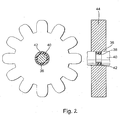
- an actuator 30, namely an annular expansion element 36 in an annular recess 38 of the shaft 40 is arranged.
- the expansion element 36 is in turn surrounded by a slotted clamping sleeve 42.
- the expansion element 36 arranged on the shaft 40 expands substantially radially when the temperature increases. During this expansion, it spreads the slotted sleeve 42. Again, the torque is transmitted to the gear 44 in turn by the resulting frictional force.
Landscapes
- Engineering & Computer Science (AREA)
- Mechanical Engineering (AREA)
- General Engineering & Computer Science (AREA)
- Rotary Pumps (AREA)
- Lubrication Of Internal Combustion Engines (AREA)
- Details Of Reciprocating Pumps (AREA)
- Applications Or Details Of Rotary Compressors (AREA)
- Eye Examination Apparatus (AREA)
Description
- Die Erfindung betrifft eine Pumpenanordnung, insbesondere für Schmierölpumpen für Verbrennungsmotoren, mit mindestens zwei Pumpenvorrichtungen, wobei die Pumpenvorrichtungen voneinander unabhängig fördern können wie im Oberbegriff von Anspruch 1 definiert ist. Eine Solche Anordnung ist z.B. aus der
DE-A-102004040436 bekannt. Es sind im Stand der Technik auch weitere zweistufige druckgeregelte Pumpen bekannt, wobei zwei Innenzahnradpumpen parallel arbeiten, wobei die zweite Stufe ab einem bestimmten Öldruck (von ca. 3 bar) in den Ansaugbereich der Pumpe zurückfördert. Bei diesen Konzepten treten volumetrische Verluste auf, die durch das Umfördern des nicht benötigten Volumenstroms anfallen. Hinzu kommen mechanische Verluste in Folge der relativ großen Reibradien der verwendeten Innenzahnradpumpen. - Es ist Aufgabe der Erfindung, eine Pumpenanordnung darzustellen, die diese Nachteile nicht aufweist.
- Die Aufgabe wird gelöst durch eine Pumpenanordnung gemäß Anspruch 1.
- Die erfinderische Idee ist dabei, eine mindestens zweitstufige Pumpe darzustellen, bei der eine Stufe kontinuierlich fördert und die andere je nach Temperatur zu- oder abgeschaltet wird, um Leistung einzusparen. Es werden zwei Konstantpumpen (z. B. Gerotor- oder Außenzahnradpumpen) verwendet. Die beiden Teilpumpen sind voneinander getrennt.
- Bevorzugt wird eine Pumpenanordnung, bei welcher die temperaturabhängig betätigbare Drehantriebsverbindung zwischen der Welle und einer Rotornabe der zweiten Pumpe angeordnet ist. Die Idee ist also, die eine Pumpe fest mit der Antriebswelle zu verbinden und die andere mit Hilfe einer temperaturabhängigen Wellen-Naben-Verbindung dazu zu schalten. Ist die notwendige Schalttemperatur erreicht, wird die zweite Pumpenstufe aktiv, und beide Volumenströme stehen dem Verbraucher zur Verfügung.
- Eine erfinderische Pumpenanordnung zeichnet sich dadurch aus, dass die mindestens zweite Pumpe durch einen temperaturabhängig veränderbaren Aktor, insbesondere durch eine Volumenausdehnung eines Aktorkörpers bei einem Temperaturanstieg, hinzugeschaltet wird.
- Beim Überschreiten einer bestimmten Temperatur wird die Verbindung hergestellt und beim Unterschreiten wieder gelöst. Die Erfindung wird nun anhand der Figuren beschrieben.
-
Figur 1 zeigt eine zweite Pumpe mit einem radial wirkenden Dehnelement. -
Figur 2 zeigt eine zweite Pumpe mit einem ringförmigen Dehnelement. - In
Figur 1 ist die sogenannte zweite Pumpe, welche temperaturabhängig mit der Welle verbindbar ist, als Zahnradpumpe mit einem Zahnrad 1 dargestellt. Das Zahnrad 1 ist auf einer Welle 28 gelagert. - In einer radialen Bohrung 26 einer Welle 28 ist temperaturabhängig veränderbarer Aktor 30, nämlich ein radial ausfahrbares Dehnelement 30 angeordnet. Die Welle 28 wird weiterhin im Bereich des Dehnelements 30 von einer geschlitzten Hülse 32 umgeben. Bei Ausdehnung des Dehnelements 30 durch Temperaturerhöhung wird die geschlitzte Hülse 32 gegen die Nabe des Zahnrades 34 gepresst und somit eine kraftschlüssige Verbindung zwischen dem Dehnelement 30 und damit der Welle 28 und dem Zahnrad 34 hergestellt.
- In
Figur 2 wird ein Aktor 30, nämlich ein ringförmiges Dehnelement 36 in einer ringförmigen Ausnehmung 38 der Welle 40 angeordnet. Das Dehnelement 36 ist wiederum von einer geschlitzten Spannhülse 42 umgeben. Das auf der Welle 40 angeordnete Dehnelement 36 dehnt sich bei Temperaturerhöhung im Wesentlichen radial aus. Während dieser Ausdehnung spreizt es die geschlitzte Hülse 42 auf. Auch hier wird das Drehmoment auf das Zahnrad 44 wiederum durch die so entstehende Reibkraft übertragen. -
- 26
- radiale Bohrung
- 28
- Welle
- 30
- radial ausfahrbares Dehnelement
- 32
- geschlitzte Hülse
- 34
- Zahnrad
- 36
- ringförmiges Dehnelement
- 38
- ringförmige Ausnehmung
- 40
- Welle
- 42
- geschlitzte Spannhülse
- 44
- Zahnrad
Claims (2)
- Pumpenanordnung, insbesondere für Schmierölpumpen für Verbrennungsmotoren, mit mindestens zwei Pumpenvorrichtungen, welche auf einer gemeinsamen Antriebswelle ( 28, 40 ) angeordnet sind, aber voneinander unabhängig fördern können, und wobei die erste Pumpe immer drehangetrieben mit der Antriebswelle (28, 40 ) verbunden ist, wobei die mindestens zweite Pumpe über eine temperaturabhängig betätigbare Drehantriebsverbindung mit der Welle (28, 40 der ersten Pumpe (98) verbindbar ist, dadurch gekennzeichnet, dass die mindestens zweite Pumpe durch einen temperaturabhängig veränderbaren Aktor (12, 22, 30, 36, 46, 62, 82), durch eine Volumenausdehnung eines Aktorkörpers bei einem Temperaturanstieg, hinzugeschaltet wird, dass der Aktor (12, 22, 30, 36, 46) eine kraftschlüssige Wellen-Naben-Verbindung herstellt, dass die Welle (28) eine radiale Ausnehmung zur Aufnahme eines radial ausdehnbaren Aktors (30) aufweist, welcher von einer geschlitzten Hülse (32) umgeben ist, so dass bei radialer Ausdehnung des Aktors (30) die geschlitzte Hülse (32) sich in ihrem Umfang ausdehnt und eine Pressverbindung zwischen dem Aktor (30) und der Rotornabe herstellt, oder dass auf der Welle (40) ein zylindrischer Ringkörper (36) als Dehnelement innerhalb einer geschlitzten Hülse (42) angeordnet ist, so dass bei radialer Ausdehnung des Ringkörpers (36) die geschlitzte Hülse (42) sich in ihrem Umfang ausdehnt und eine Pressverbindung zwischen Aktor (36) und Rotornabe herstellt.
- Pumpenanordnung nach Anspruch 1, dadurch gekennzeichnet, dass die temperaturabhängig betätigbare Drehantriebsverbindung zwischen der Welle (28, 40) und einer Rotornabe der zweiten Pumpe angeordnet ist.
Applications Claiming Priority (2)
| Application Number | Priority Date | Filing Date | Title |
|---|---|---|---|
| DE102005051463 | 2005-10-27 | ||
| PCT/DE2006/001823 WO2007048380A1 (de) | 2005-10-27 | 2006-10-17 | Pumpenanordnung |
Publications (2)
| Publication Number | Publication Date |
|---|---|
| EP1943423A1 EP1943423A1 (de) | 2008-07-16 |
| EP1943423B1 true EP1943423B1 (de) | 2012-05-02 |
Family
ID=37654812
Family Applications (1)
| Application Number | Title | Priority Date | Filing Date |
|---|---|---|---|
| EP06805431A Not-in-force EP1943423B1 (de) | 2005-10-27 | 2006-10-17 | Pumpenanordnung |
Country Status (4)
| Country | Link |
|---|---|
| EP (1) | EP1943423B1 (de) |
| AT (1) | ATE556223T1 (de) |
| DE (1) | DE112006002561A5 (de) |
| WO (1) | WO2007048380A1 (de) |
Families Citing this family (3)
| Publication number | Priority date | Publication date | Assignee | Title |
|---|---|---|---|---|
| AT505644B1 (de) | 2007-09-06 | 2011-09-15 | Tcg Unitech Systemtechnik Gmbh | Kühlmittelpumpe |
| AT513976B1 (de) * | 2013-06-19 | 2014-09-15 | Avl List Gmbh | Schaltbare Zahnradpumpe |
| DE102014117166B4 (de) * | 2014-11-24 | 2016-07-07 | Netzsch Pumpen & Systeme Gmbh | Drehkolbenpumpe, verfahren zur fixierung von drehkolben einer drehkolbenpumpe und verfahren zur demontage von drehkolben einer drehkolbenpumpe |
Family Cites Families (9)
| Publication number | Priority date | Publication date | Assignee | Title |
|---|---|---|---|---|
| GB1099700A (en) * | 1963-12-30 | 1968-01-17 | Mirrlees Engineers Ltd | Closed-circuit force-feed lubrication system for marine diesel engines and other devices requiring lubrication |
| US5326232A (en) * | 1993-04-20 | 1994-07-05 | General Motors Corporation | Two stage pump assembly with mechanical disconnect |
| JPH07332086A (ja) * | 1994-06-14 | 1995-12-19 | Unisia Jecs Corp | 渦巻ポンプ |
| DE19752372A1 (de) * | 1997-11-26 | 1999-05-27 | Guenther Dipl Ing Beez | Regelbare Kreiselpumpe, insbesondere für Verbrennungsmotore |
| DE19914440A1 (de) * | 1999-03-30 | 2000-10-05 | Volkswagen Ag | Vorrichtung zur temperaturabhängigen Verbindung von Bauteilen |
| DE19933484A1 (de) * | 1999-07-16 | 2001-01-18 | Bayerische Motoren Werke Ag | Innenzahnradpumpen umfassendes Pumpenaggregat, insbesondere für das Schmiersystem einer Brennkraftmaschine |
| DE10223466B4 (de) * | 2001-05-31 | 2015-07-02 | Magna Powertrain Hückeswagen GmbH | Pumpe |
| DE102004040436A1 (de) * | 2004-08-20 | 2005-10-20 | Audi Ag | Ölpumpe mit wenigstens zwei Pumpenstufen und Verfahren zum Betreiben einer Ölpumpe |
| DE102005032226A1 (de) * | 2005-07-09 | 2007-01-18 | Daimlerchrysler Ag | Schmiermittelversorgungssystem eines Kraftfahrzeugs |
-
2006
- 2006-10-17 AT AT06805431T patent/ATE556223T1/de active
- 2006-10-17 DE DE112006002561T patent/DE112006002561A5/de not_active Withdrawn
- 2006-10-17 WO PCT/DE2006/001823 patent/WO2007048380A1/de not_active Ceased
- 2006-10-17 EP EP06805431A patent/EP1943423B1/de not_active Not-in-force
Also Published As
| Publication number | Publication date |
|---|---|
| ATE556223T1 (de) | 2012-05-15 |
| DE112006002561A5 (de) | 2008-07-03 |
| EP1943423A1 (de) | 2008-07-16 |
| WO2007048380A1 (de) | 2007-05-03 |
Similar Documents
| Publication | Publication Date | Title |
|---|---|---|
| US6293382B1 (en) | Friction plate for wet clutch | |
| DE3840691A1 (de) | Radialkolbenpumpe | |
| DE19881422B4 (de) | Nehmerzylindergehäuse aus Kunststoff, in das eine Führungshülse aus Metall eingesetzt ist | |
| EP1395454A1 (de) | Hybridantriebssystem mit drehmomentwandler | |
| DE112015005074T5 (de) | Elektrische pumpe | |
| DE102015219771A1 (de) | Fördereinrichtung für ein Kraftfahrzeug | |
| EP0666422B1 (de) | Lagerung und Antrieb der Rotoren eines Schraubenrotorverdichters | |
| DE202015105244U1 (de) | Pumpe-Motor-Einheit | |
| DE69913452T2 (de) | Abgestufte Dichtung und Buchse | |
| EP2002123B1 (de) | Fluidpumpe | |
| EP0719393B1 (de) | Einrichtung zur moment-übertragung einer antriebseinheit auf ein getriebe mit einem hydrodynamischen wandler | |
| WO2015082223A1 (de) | Regelbare pumpe für eine verbrennungskraftmaschine | |
| WO2007128273A2 (de) | Vorrichtung zum verbinden von komponenten mit einer nabe | |
| DE602004002493T2 (de) | Flüssigkeitskupplung | |
| EP1354150B1 (de) | Hydrodynamische kopplungseinrichtung | |
| WO2007048380A1 (de) | Pumpenanordnung | |
| DE102015219204A1 (de) | Mehrfachpumpe und Getriebe | |
| EP1945955B1 (de) | Fluidpumpe | |
| DE102016210821B4 (de) | Flügelzellenpumpe mit zwei Rotoren | |
| DE102005032226A1 (de) | Schmiermittelversorgungssystem eines Kraftfahrzeugs | |
| EP1582740B1 (de) | Hochdruckpumpe mit integriertem Hochdruckspeicher | |
| DE102012214764A1 (de) | Befestigungsanordnung zur Verbindung eines Nockenwellenverstellers mit einem Nockenwellenende einer Nockenwelle | |
| DE102023105959A1 (de) | Flügelzellenpumpe, Schaltgetriebe und Kraftfahrzeug mit einem solchen Getriebe | |
| GB2333580A (en) | Pump assembly | |
| DE102004024728B3 (de) | Schalteinrichtung für mehrstufige Ölpumpen |
Legal Events
| Date | Code | Title | Description |
|---|---|---|---|
| PUAI | Public reference made under article 153(3) epc to a published international application that has entered the european phase |
Free format text: ORIGINAL CODE: 0009012 |
|
| 17P | Request for examination filed |
Effective date: 20080527 |
|
| AK | Designated contracting states |
Kind code of ref document: A1 Designated state(s): AT BE BG CH CY CZ DE DK EE ES FI FR GB GR HU IE IS IT LI LT LU LV MC NL PL PT RO SE SI SK TR |
|
| RIN1 | Information on inventor provided before grant (corrected) |
Inventor name: RISCHE, OLAF Inventor name: SCHULZ-ANDRES, HEIKO Inventor name: KAMARYS, DIRK |
|
| RIN1 | Information on inventor provided before grant (corrected) |
Inventor name: KAMARYS, DIRK Inventor name: RISCHE, OLAF Inventor name: SCHULZ-ANDRES, HEIKO |
|
| RAP1 | Party data changed (applicant data changed or rights of an application transferred) |
Owner name: IXETIC HUECKESWAGEN GMBH |
|
| GRAP | Despatch of communication of intention to grant a patent |
Free format text: ORIGINAL CODE: EPIDOSNIGR1 |
|
| DAX | Request for extension of the european patent (deleted) | ||
| RIN1 | Information on inventor provided before grant (corrected) |
Inventor name: SCHULZ-ANDRES, HEIKO Inventor name: KAMARYS, DIRK Inventor name: RISCHE, OLAF |
|
| GRAS | Grant fee paid |
Free format text: ORIGINAL CODE: EPIDOSNIGR3 |
|
| GRAA | (expected) grant |
Free format text: ORIGINAL CODE: 0009210 |
|
| AK | Designated contracting states |
Kind code of ref document: B1 Designated state(s): AT BE BG CH CY CZ DE DK EE ES FI FR GB GR HU IE IS IT LI LT LU LV MC NL PL PT RO SE SI SK TR |
|
| REG | Reference to a national code |
Ref country code: GB Ref legal event code: FG4D Free format text: NOT ENGLISH |
|
| REG | Reference to a national code |
Ref country code: CH Ref legal event code: EP Ref country code: AT Ref legal event code: REF Ref document number: 556223 Country of ref document: AT Kind code of ref document: T Effective date: 20120515 |
|
| REG | Reference to a national code |
Ref country code: IE Ref legal event code: FG4D Free format text: LANGUAGE OF EP DOCUMENT: GERMAN |
|
| REG | Reference to a national code |
Ref country code: DE Ref legal event code: R096 Ref document number: 502006011401 Country of ref document: DE Effective date: 20120705 |
|
| REG | Reference to a national code |
Ref country code: NL Ref legal event code: VDEP Effective date: 20120502 |
|
| REG | Reference to a national code |
Ref country code: LT Ref legal event code: MG4D Effective date: 20120516 |
|
| PG25 | Lapsed in a contracting state [announced via postgrant information from national office to epo] |
Ref country code: IS Free format text: LAPSE BECAUSE OF FAILURE TO SUBMIT A TRANSLATION OF THE DESCRIPTION OR TO PAY THE FEE WITHIN THE PRESCRIBED TIME-LIMIT Effective date: 20120902 Ref country code: SE Free format text: LAPSE BECAUSE OF FAILURE TO SUBMIT A TRANSLATION OF THE DESCRIPTION OR TO PAY THE FEE WITHIN THE PRESCRIBED TIME-LIMIT Effective date: 20120502 Ref country code: PL Free format text: LAPSE BECAUSE OF FAILURE TO SUBMIT A TRANSLATION OF THE DESCRIPTION OR TO PAY THE FEE WITHIN THE PRESCRIBED TIME-LIMIT Effective date: 20120502 Ref country code: CY Free format text: LAPSE BECAUSE OF FAILURE TO SUBMIT A TRANSLATION OF THE DESCRIPTION OR TO PAY THE FEE WITHIN THE PRESCRIBED TIME-LIMIT Effective date: 20120502 Ref country code: FI Free format text: LAPSE BECAUSE OF FAILURE TO SUBMIT A TRANSLATION OF THE DESCRIPTION OR TO PAY THE FEE WITHIN THE PRESCRIBED TIME-LIMIT Effective date: 20120502 Ref country code: LT Free format text: LAPSE BECAUSE OF FAILURE TO SUBMIT A TRANSLATION OF THE DESCRIPTION OR TO PAY THE FEE WITHIN THE PRESCRIBED TIME-LIMIT Effective date: 20120502 |
|
| PG25 | Lapsed in a contracting state [announced via postgrant information from national office to epo] |
Ref country code: PT Free format text: LAPSE BECAUSE OF FAILURE TO SUBMIT A TRANSLATION OF THE DESCRIPTION OR TO PAY THE FEE WITHIN THE PRESCRIBED TIME-LIMIT Effective date: 20120903 Ref country code: SI Free format text: LAPSE BECAUSE OF FAILURE TO SUBMIT A TRANSLATION OF THE DESCRIPTION OR TO PAY THE FEE WITHIN THE PRESCRIBED TIME-LIMIT Effective date: 20120502 Ref country code: GR Free format text: LAPSE BECAUSE OF FAILURE TO SUBMIT A TRANSLATION OF THE DESCRIPTION OR TO PAY THE FEE WITHIN THE PRESCRIBED TIME-LIMIT Effective date: 20120803 Ref country code: LV Free format text: LAPSE BECAUSE OF FAILURE TO SUBMIT A TRANSLATION OF THE DESCRIPTION OR TO PAY THE FEE WITHIN THE PRESCRIBED TIME-LIMIT Effective date: 20120502 |
|
| PG25 | Lapsed in a contracting state [announced via postgrant information from national office to epo] |
Ref country code: SK Free format text: LAPSE BECAUSE OF FAILURE TO SUBMIT A TRANSLATION OF THE DESCRIPTION OR TO PAY THE FEE WITHIN THE PRESCRIBED TIME-LIMIT Effective date: 20120502 Ref country code: NL Free format text: LAPSE BECAUSE OF FAILURE TO SUBMIT A TRANSLATION OF THE DESCRIPTION OR TO PAY THE FEE WITHIN THE PRESCRIBED TIME-LIMIT Effective date: 20120502 Ref country code: CZ Free format text: LAPSE BECAUSE OF FAILURE TO SUBMIT A TRANSLATION OF THE DESCRIPTION OR TO PAY THE FEE WITHIN THE PRESCRIBED TIME-LIMIT Effective date: 20120502 Ref country code: EE Free format text: LAPSE BECAUSE OF FAILURE TO SUBMIT A TRANSLATION OF THE DESCRIPTION OR TO PAY THE FEE WITHIN THE PRESCRIBED TIME-LIMIT Effective date: 20120502 Ref country code: DK Free format text: LAPSE BECAUSE OF FAILURE TO SUBMIT A TRANSLATION OF THE DESCRIPTION OR TO PAY THE FEE WITHIN THE PRESCRIBED TIME-LIMIT Effective date: 20120502 Ref country code: RO Free format text: LAPSE BECAUSE OF FAILURE TO SUBMIT A TRANSLATION OF THE DESCRIPTION OR TO PAY THE FEE WITHIN THE PRESCRIBED TIME-LIMIT Effective date: 20120502 |
|
| PGFP | Annual fee paid to national office [announced via postgrant information from national office to epo] |
Ref country code: DE Payment date: 20121211 Year of fee payment: 7 |
|
| PG25 | Lapsed in a contracting state [announced via postgrant information from national office to epo] |
Ref country code: IT Free format text: LAPSE BECAUSE OF FAILURE TO SUBMIT A TRANSLATION OF THE DESCRIPTION OR TO PAY THE FEE WITHIN THE PRESCRIBED TIME-LIMIT Effective date: 20120502 |
|
| PLBE | No opposition filed within time limit |
Free format text: ORIGINAL CODE: 0009261 |
|
| STAA | Information on the status of an ep patent application or granted ep patent |
Free format text: STATUS: NO OPPOSITION FILED WITHIN TIME LIMIT |
|
| 26N | No opposition filed |
Effective date: 20130205 |
|
| BERE | Be: lapsed |
Owner name: IXETIC HUCKESWAGEN G.M.B.H. Effective date: 20121031 |
|
| PG25 | Lapsed in a contracting state [announced via postgrant information from national office to epo] |
Ref country code: ES Free format text: LAPSE BECAUSE OF FAILURE TO SUBMIT A TRANSLATION OF THE DESCRIPTION OR TO PAY THE FEE WITHIN THE PRESCRIBED TIME-LIMIT Effective date: 20120813 |
|
| REG | Reference to a national code |
Ref country code: DE Ref legal event code: R097 Ref document number: 502006011401 Country of ref document: DE Effective date: 20130205 |
|
| PG25 | Lapsed in a contracting state [announced via postgrant information from national office to epo] |
Ref country code: MC Free format text: LAPSE BECAUSE OF NON-PAYMENT OF DUE FEES Effective date: 20121031 |
|
| REG | Reference to a national code |
Ref country code: CH Ref legal event code: PL |
|
| GBPC | Gb: european patent ceased through non-payment of renewal fee |
Effective date: 20121017 |
|
| REG | Reference to a national code |
Ref country code: IE Ref legal event code: MM4A |
|
| REG | Reference to a national code |
Ref country code: FR Ref legal event code: ST Effective date: 20130628 |
|
| PG25 | Lapsed in a contracting state [announced via postgrant information from national office to epo] |
Ref country code: CH Free format text: LAPSE BECAUSE OF NON-PAYMENT OF DUE FEES Effective date: 20121031 Ref country code: BE Free format text: LAPSE BECAUSE OF NON-PAYMENT OF DUE FEES Effective date: 20121031 Ref country code: BG Free format text: LAPSE BECAUSE OF FAILURE TO SUBMIT A TRANSLATION OF THE DESCRIPTION OR TO PAY THE FEE WITHIN THE PRESCRIBED TIME-LIMIT Effective date: 20120802 Ref country code: IE Free format text: LAPSE BECAUSE OF NON-PAYMENT OF DUE FEES Effective date: 20121017 Ref country code: LI Free format text: LAPSE BECAUSE OF NON-PAYMENT OF DUE FEES Effective date: 20121031 Ref country code: GB Free format text: LAPSE BECAUSE OF NON-PAYMENT OF DUE FEES Effective date: 20121017 |
|
| PG25 | Lapsed in a contracting state [announced via postgrant information from national office to epo] |
Ref country code: FR Free format text: LAPSE BECAUSE OF NON-PAYMENT OF DUE FEES Effective date: 20121031 |
|
| REG | Reference to a national code |
Ref country code: AT Ref legal event code: MM01 Ref document number: 556223 Country of ref document: AT Kind code of ref document: T Effective date: 20121031 |
|
| PG25 | Lapsed in a contracting state [announced via postgrant information from national office to epo] |
Ref country code: AT Free format text: LAPSE BECAUSE OF NON-PAYMENT OF DUE FEES Effective date: 20121031 |
|
| PG25 | Lapsed in a contracting state [announced via postgrant information from national office to epo] |
Ref country code: TR Free format text: LAPSE BECAUSE OF FAILURE TO SUBMIT A TRANSLATION OF THE DESCRIPTION OR TO PAY THE FEE WITHIN THE PRESCRIBED TIME-LIMIT Effective date: 20120502 |
|
| PG25 | Lapsed in a contracting state [announced via postgrant information from national office to epo] |
Ref country code: LU Free format text: LAPSE BECAUSE OF NON-PAYMENT OF DUE FEES Effective date: 20121017 |
|
| PG25 | Lapsed in a contracting state [announced via postgrant information from national office to epo] |
Ref country code: HU Free format text: LAPSE BECAUSE OF FAILURE TO SUBMIT A TRANSLATION OF THE DESCRIPTION OR TO PAY THE FEE WITHIN THE PRESCRIBED TIME-LIMIT Effective date: 20061017 |
|
| REG | Reference to a national code |
Ref country code: DE Ref legal event code: R119 Ref document number: 502006011401 Country of ref document: DE Effective date: 20140501 |
|
| PG25 | Lapsed in a contracting state [announced via postgrant information from national office to epo] |
Ref country code: DE Free format text: LAPSE BECAUSE OF NON-PAYMENT OF DUE FEES Effective date: 20140501 |