EP1942555B1 - Procédé et appareil pour antenne à direction de WLAN - Google Patents
Procédé et appareil pour antenne à direction de WLAN Download PDFInfo
- Publication number
- EP1942555B1 EP1942555B1 EP08154140A EP08154140A EP1942555B1 EP 1942555 B1 EP1942555 B1 EP 1942555B1 EP 08154140 A EP08154140 A EP 08154140A EP 08154140 A EP08154140 A EP 08154140A EP 1942555 B1 EP1942555 B1 EP 1942555B1
- Authority
- EP
- European Patent Office
- Prior art keywords
- antenna
- signal
- access point
- sme
- metrics
- Prior art date
- Legal status (The legal status is an assumption and is not a legal conclusion. Google has not performed a legal analysis and makes no representation as to the accuracy of the status listed.)
- Expired - Lifetime
Links
- 238000000034 method Methods 0.000 title claims abstract description 65
- 230000006854 communication Effects 0.000 claims description 12
- 238000004891 communication Methods 0.000 claims description 11
- 230000004044 response Effects 0.000 claims description 10
- 238000005259 measurement Methods 0.000 claims 4
- 230000008569 process Effects 0.000 description 47
- 238000010586 diagram Methods 0.000 description 16
- 239000000523 sample Substances 0.000 description 10
- 230000005404 monopole Effects 0.000 description 6
- 238000003491 array Methods 0.000 description 4
- 230000005540 biological transmission Effects 0.000 description 4
- 238000005562 fading Methods 0.000 description 4
- 230000015556 catabolic process Effects 0.000 description 3
- 230000008859 change Effects 0.000 description 3
- 238000006731 degradation reaction Methods 0.000 description 3
- 230000000694 effects Effects 0.000 description 3
- 230000001939 inductive effect Effects 0.000 description 3
- 238000013459 approach Methods 0.000 description 2
- 230000008878 coupling Effects 0.000 description 2
- 238000010168 coupling process Methods 0.000 description 2
- 238000005859 coupling reaction Methods 0.000 description 2
- 230000000737 periodic effect Effects 0.000 description 2
- 238000012360 testing method Methods 0.000 description 2
- 230000009471 action Effects 0.000 description 1
- 230000010267 cellular communication Effects 0.000 description 1
- 230000006870 function Effects 0.000 description 1
- 230000001151 other effect Effects 0.000 description 1
- 230000010363 phase shift Effects 0.000 description 1
- 238000012545 processing Methods 0.000 description 1
- 238000013442 quality metrics Methods 0.000 description 1
- 230000011664 signaling Effects 0.000 description 1
Images


Classifications
-
- H—ELECTRICITY
- H04—ELECTRIC COMMUNICATION TECHNIQUE
- H04B—TRANSMISSION
- H04B7/00—Radio transmission systems, i.e. using radiation field
- H04B7/02—Diversity systems; Multi-antenna system, i.e. transmission or reception using multiple antennas
- H04B7/04—Diversity systems; Multi-antenna system, i.e. transmission or reception using multiple antennas using two or more spaced independent antennas
- H04B7/06—Diversity systems; Multi-antenna system, i.e. transmission or reception using multiple antennas using two or more spaced independent antennas at the transmitting station
- H04B7/0686—Hybrid systems, i.e. switching and simultaneous transmission
- H04B7/0695—Hybrid systems, i.e. switching and simultaneous transmission using beam selection
-
- H—ELECTRICITY
- H04—ELECTRIC COMMUNICATION TECHNIQUE
- H04B—TRANSMISSION
- H04B7/00—Radio transmission systems, i.e. using radiation field
- H04B7/02—Diversity systems; Multi-antenna system, i.e. transmission or reception using multiple antennas
- H04B7/04—Diversity systems; Multi-antenna system, i.e. transmission or reception using multiple antennas using two or more spaced independent antennas
- H04B7/08—Diversity systems; Multi-antenna system, i.e. transmission or reception using multiple antennas using two or more spaced independent antennas at the receiving station
- H04B7/0868—Hybrid systems, i.e. switching and combining
- H04B7/088—Hybrid systems, i.e. switching and combining using beam selection
-
- H—ELECTRICITY
- H04—ELECTRIC COMMUNICATION TECHNIQUE
- H04B—TRANSMISSION
- H04B7/00—Radio transmission systems, i.e. using radiation field
- H04B7/02—Diversity systems; Multi-antenna system, i.e. transmission or reception using multiple antennas
- H04B7/04—Diversity systems; Multi-antenna system, i.e. transmission or reception using multiple antennas using two or more spaced independent antennas
- H04B7/06—Diversity systems; Multi-antenna system, i.e. transmission or reception using multiple antennas using two or more spaced independent antennas at the transmitting station
- H04B7/0613—Diversity systems; Multi-antenna system, i.e. transmission or reception using multiple antennas using two or more spaced independent antennas at the transmitting station using simultaneous transmission
- H04B7/0615—Diversity systems; Multi-antenna system, i.e. transmission or reception using multiple antennas using two or more spaced independent antennas at the transmitting station using simultaneous transmission of weighted versions of same signal
- H04B7/0617—Diversity systems; Multi-antenna system, i.e. transmission or reception using multiple antennas using two or more spaced independent antennas at the transmitting station using simultaneous transmission of weighted versions of same signal for beam forming
-
- H—ELECTRICITY
- H04—ELECTRIC COMMUNICATION TECHNIQUE
- H04W—WIRELESS COMMUNICATION NETWORKS
- H04W16/00—Network planning, e.g. coverage or traffic planning tools; Network deployment, e.g. resource partitioning or cells structures
- H04W16/24—Cell structures
- H04W16/28—Cell structures using beam steering
Definitions
- the 802.11 Institute of Electrical and Electronic Engineers (IEEE) standards defines a specification for stations to be moved within a facility and remain connected to a Wireless Local Area Network (WLAN) via Radio Frequency (RF) transmissions to Access Points (AP) connected to a wired network.
- a physical layer in-the stations and access points controls the modulation and signaling format used by the stations and access points to communicate.
- MAC Medium Access Control
- MAC Medium Access Control
- the physical layer in the station and access points first establish wireless communication with each other, followed by the MAC layer establishing access to the network via an access point.
- the signals are RF signals, transmitted and received by monopole antennas.
- a monopole antenna provides transmissions in all directions generally in a horizontal plane.
- Monopole antennas are susceptible to effects that degrade the quality of communication between the station and access points, such as reflection or diffraction of radio wave signals caused by intervening walls, desks, people, etc., multipath, normal fading, Rayleigh fading, and so forth. As a result, efforts have been made to mitigate signal degradation caused by these effects.
- Antenna diversity counteracts the degradation of RF signals.
- Antenna diversity uses two antennas that are connected to a transmitter/receiver via an antenna diversity switch.
- the theory behind using two antennas for antenna diversity is that, at any given time, one of the two antennas is likely receiving a signal that is not affected by the effects of, say, multi-path fading.
- the system using the two antennas selects the unaffected antenna via the antenna diversity switch
- US2001/031648 discloses an antenna apparatus that can increase capacity in a cellular communication system.
- the antenna operates in conjunction with a mobile subscriber unit and provides a plurality of antenna elements, each coupled to a respective signal control component such as a phase shifter.
- the phase shift for each antenna element is programmed for optimum reception during, for example, an idle mode when a pilot signal is received.
- the antenna array creates a beam former for signals to be transmitted from the mobile subscriber unit, and a directional receiving array to more optimally detect and receive signals transmitted from the base station.
- US2001/028639 discloses a wireless local area network station which is adapted to transmit and receive signals within a communication cell comprising a carrier detect zone and a defer zone around an access point.
- the network station associates with the access point by transmitting an association request and by receiving an association response during entry of the network station into the cell.
- the network station is arranged to receive preferred level values for the carrier detect threshold and defer behaviour threshold from the access point and to store these preference values in its memory for use during operation while being associated with the access point.
- each of the diversity antennas is an omni-directional antenna (e.g., monopole antenna), so the system employing the antenna cannot steer the antenna away from a source of interference or achieve any gain beyond what one omni-directional antenna inherently provides.
- omni-directional antenna e.g., monopole antenna
- the principles of the present invention provide a technique for steering a directional/multi-element antenna in an 802.11 protocol system for a station to communicate with the Access Point (AP) in an Extended Service Set (ESS) network or other network structure having wireless access points.
- This approach has minimal impact on network efficiency as the approach can be accomplished within the current 802.11 protocols.
- a reference herein to this "802.11 protocol” or "802.11 standard” includes the 802.11, 802.11a, 802.11b, and 802.11g protocols and standards.
- the technique can come into operation before and after an 802.11 station has authenticated and associated with a network access point connected to a wired network.
- the wired network is referred to interchangeably herein as a distribution system.
- the initial antenna scan is accomplished within the Medium Access Control (MAC) layer.
- MAC Medium Access Control
- the steering process cycles through the available antenna positions and monitors a signal metric associated with a beacon signal or other predetermined signal to determine a best antenna pointing direction.
- the process cycles through the antenna positions and monitors a signal metric associated with a probe response signal to determine the best antenna position.
- additional scans may be performed, optionally based on a determination that the received signal level has dropped below some threshold.
- a directional antenna in a wireless local area network (WLAN) environment results in improved range and data rates for users and increases network efficiency for the network.
- WLAN wireless local area network
- Fig. 1A is a block diagram of a wireless local area network (WLAN) 100 having a distribution system 105.
- Access points 110a, 110b, and 110c are connected to the distribution system 105 via wired connections such as wired Local Area Networks (LANs).
- LANs Local Area Networks
- Each of the access points 110 has a respective zone 115a, 115b, 115c in which it is capable of transmitting and receiving RF signals to and from stations 120a, 120b, and 120c, which are supported with Wireless Local Area Network (WLAN) hardware and software to access the distribution system 105.
- WLAN Wireless Local Area Network
- Fig. 1B is a block diagram of a subset of the network 100 in which the second station 120b, employing the principles of the present invention, is shown in more detail.
- the second station 120b generates directive antenna lobes 130a - 130i (collectively, lobes 130) from a directive antenna array.
- the directive antenna array is interchangeably referred to herein as a directional antenna.
- the second station 120b uses the directive antenna array to scan its environment to determine a direction to a "best" access point 110a, 110b.
- the scan may be performed in a passive mode, in which the second station 120b listens for beacon signals emitted by the access points 110a, 110b.
- the beacon signals are generally sent every 100 msec. So, for the nine antenna lobes 130, the process takes about 1 second to cycle through the antenna lobe directions and determine the best angle.
- the second station 120b sends a probe signal to the access points 110a, 110b and receives responses to the probe signal from the access points 110a, 110b. This probe and response process may be repeated for each antenna scan angle.
- the second station 120b uses the directive antenna array to scan the RF airways in search of signals from the access points 110.
- the second station 110b measures the received beacon signal or probe response and calculates a respective metric for that scan angle. Examples of the metrics include Received Signal Strength Indication (RSSI), Carrier-to-Interference ratio (C/I), Signal-to-Noise ratio (Eb/No), or other suitable measure of the quality of the received signal or signal environment.
- RSSI Received Signal Strength Indication
- C/I Carrier-to-Interference ratio
- Eb/No Signal-to-Noise ratio
- the second station 110b can determine a "best" direction to communicate with one of the access points 110a, 110b.
- the scans may occur before or after the second station 110b has authenticated and associated with the distribution system 105.
- the initial antenna scan may be accomplished within the Medium Access Control (MAC) layer.
- the initial scan may be accomplished external from the MAC layer.
- scans occurring after the second station 110b has authenticated and associated with the distribution system 105 may be accomplished within the MAC layer or by processes occurring external from the MAC layer.
- MAC Medium Access Control
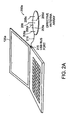
- Fig. 2A is a diagram of the first station 120a that is equipped with a directive antenna array 200a.
- the directive antenna array 200a is external from the chassis of the first station 120a.
- the directive antenna array 200a includes five monopole passive antenna elements 205a, 205b, 205c, 205d, and 205e (collectively, passive antenna elements 205) and one monopole, active antenna element 206.
- the directive antenna element 200a is connected to the first station 120a via a Universal System Bus (USB) port 215.
- USB Universal System Bus
- the passive antenna elements 205 in the directive antenna array 200a are parasitically coupled to the active antenna element 206 to facilitate beam angle direction changes. Changing the beam angle direction may allow for at least one antenna beam to be rotated 360° in increments associated with the number of passive antenna elements 205. Less than full 360° rotations and sub-incremental direction changes are also possible.
- the directive antenna array 200a supports an omni-directional mode defined by an omni-directional or substantially omni-directional antenna pattern (not shown).
- the stations 120 may use the omni-directional antenna pattern for Carrier Sense prior to transmission or to assess by way of comparison current performance of directional mode versus omni-directional mode.
- the stations 120 may revert to an omni-only antenna configuration since communicating with other stations 120 can occur in any direction.
- Fig. 2B is another embodiment of the first station 120a that includes a directive antenna array 200b deployed on a Personal Computer Memory Card International Association (PCMCIA) card 220.
- the PCMCIA card 220 is disposed in the chassis of the first station 120a in a typical manner.
- the PCMCIA card 220 communicates with a processor (not shown) in the first station 120a via a typical computer bus.
- the directive antenna array 200b deployed as the PCMCIA card 220 provides the same functionality as the stand-alone directive antenna array 200a discussed above in reference to Fig. 2A .
- the directive antenna arrays 200b may include one active antenna element electromagnetically coupled to multiple passive antenna elements.
- the directive antenna arrays 200 may include multiple active and multiple passive antenna elements.
- the directive antenna arrays 200 may include multiple active antenna elements and a single passive antenna element.
- the directive antenna arrays 200 may include all active antenna elements.
- Fig. 3A is a detailed view of the directive antenna array 200a that includes the multiple passive antenna elements 205 and one active antenna element 206 as discussed above in reference to Figs. 2A and 2B .
- the directive antenna array 200a may also include a ground plane 330 to which the passive antenna elements 206 are electrically connected.
- one state of the directive antenna array 200a provides a directive antenna lobe 300 angled away from antenna elements 205a and 205e.
- the mutual coupling between the active antenna element 206 and the passive antenna elements 205 allows the mode settings of the passive antenna elements 205 to control the direction of the directive antenna lobe 300.
- different mode combinations result in different antenna lobe 300 patterns and angles.
- Fig. 3B is a schematic diagram of an example circuit that can be used to set the passive antenna element 205a in a reflective or transmissive mode.
- the reflective mode is indicated by a representative "elongated" dashed line 305
- the transmissive mode is indicated by a "shortened” dashed line 310.
- the representative dashed lines 305 and 310 are also representative of the electrical termination associated with the passive antenna element 205a. For example, electrically connecting the passive antenna element 205a to a ground plane 330 via an inductive element 320 sets the passive antenna element 205a in reflective mode, and electrically connecting the passive antenna element 205a to the ground plane 330 via a capacitive element 325 sets the passive antenna element 205a in transmissive mode.
- the switch 315 may be a mechanical or electrical switch capable of electrically connecting the passive antenna element 205a to the ground plane 330 or reactive element in a manner suitable for this application.
- the switch 315 is set via a control signal 335 in a typical switch control manner.
- both passive antenna elements 205a and 205e are connected to the ground plane 330 via respective inductive elements 320.
- the other passive antenna elements 205b, 205c, and 205d are electrically connected to the ground plane 330 via respective capacitive elements 325. Capacitively coupling all of the passive elements 325 causes the directive antenna array 200a to form an omni-directional antenna beam pattern.
- a SME 800, MAC layer 805, and physical (PHY) layer 810 are shown in a generalized arrangement, sometimes referred to as an 802.11 stack.
- the SME 800 is in communication with the MAC layer 805 and PHY layer 810.
- the SME 800 is a layer-independent entity that may be viewed as a separate management plane or residing "off to the side" from the MAC layer 805 and PHY layer 810.
- the SME 800, MAC layer 805, and PHY layer 810 may communicate through various media, such as via a system bus, physical cable interconnection, or network connection.
- the SME 800 may be a standalone software application or applet executing in a personal computer that is being used as a station 120a, as described above.
- the MAC layer 805 and PHY layer 810 may be implemented in software or firmware operating in a plug-in PCI or PCMCIA card 220 installed in the station 120a.
- the MAC layer 805 and PHY layer 810 use standard protocols in accordance with the 802.11 standards.
- the SME 800 can be downloaded from a server on the Internet (not shown), for example, and be capable of interacting with the MAC layer 805 and PHY layer 810 in a plug-and-play manner.
- the SME 800 may be partially or fully updated on occasion to facilitate updating or exchanging the directive antenna array 205a with an antenna array having a different configuration.
- the SME 800 may include an interface driver (not shown).
- the interface driver is sometimes included as part of the SME 800 while other times provided as a separate module.
- the interface module can send commands to an antenna controller 815 and receive feedback from the antenna controller 815. The commands cause the directive antenna array 205a to steer an antenna beam during a scan when searching for a "best" access point 110.
- the MAC layer 805 can determine signal metrics, such as signal-to-noise ratio, associated with RF signals communicated via the directive antenna 205a or other form of antenna.
- the MAC layer 805 employs the PHY layer 810 to convert and RF signal to a baseband signal, and vice-versa.
- the MAC layer 805 can use the PHY layer 810 to provide signal-related parameters, such as Received Signal Strength Indication (RSSI), Signal Quality (SQ), and indicated data rate.
- RSSI Received Signal Strength Indication
- SQ Signal Quality
- the MAC layer 805 may then provide the metrics to the SME 800 in the form of a datum associated with one antenna beam direction or a table of data associated with multiple antenna beam directions.
- the SME 800 may cause the MAC layer 805 to provide the metrics through use of commands or requests.
- the SME 800 may cause the MAC layer 805 to provide metrics associated with respective beam angles of the directive antenna array 205a. Based on the metrics and predetermined criteria, the SME 800 may steer the directive antenna array 205a to a selected direction associated with an access point 110.
- the MAC layer 805 may be caused to determine the metrics as a function of received RF energy by the directive antenna array 205a in the respective beam angles. For example, the metrics may be higher for signal strength of a beacon signal received from a first access point 110a as compared to signal strength of a beacon signal received from a second access point 110b.
- the SME 800 may cause the MAC layer 805 (i) to transmit a signal via the physical layer 810 to at least one access point 110a, 110b, or 110c and (ii) to measure a response from the access point(s) 110.
- the MAC layer 805 may also provide the metrics or table of metrics to the SME 800 based on previously calculated or measured metrics. For example, a periodic or event-driven event may cause the MAC layer 805 to determine the metrics and provide the metrics to the SME 800 on an "as needed," "as requested,” or predefined basis.
- the station 120a may associate with the distribution system via the access point 110, and the MAC layer 805 may provide the metrics to the SME 800 before or after the associating with the distribution system, optionally in a preselected manner.
- the SME 800 may issue commands to the antenna controller 815, which sends control signals 820 to the directive antenna array 205a.
- the control signals 820 may change the state of connection to reactances 320, 325 associated with the antenna elements 205 in the directive antenna array 200a, which, in turn, causes the antenna beam angle to change.
- the SME 800 may coordinate this action with causing the MAC layer 805 to provide the metrics associated with the antenna beam angles.
- the SME 800 may command the directive antenna array 200 to steer its antenna beam from angle to angle in a step-and-hold manner while concurrently commanding the MAC layer 805 to measure the signal strength in a corresponding wait-and-measure manner until a metric is associated with each access point 110 at each antenna beam angle.
- the SME 800 may issue further commands to the antenna controller 815 to steer the antenna beam in a direction associated with an access point 110.
- the antenna beam may be steered to point directly toward an access point 110a or in the direction of a stronger multi-path that is associated with the same access point 110a. In this way, the SME 800 can use the best path for associating the station 120a with the selected access point 110a.
- the SME 800 may invoke an omni-directional beam angle by the directive antenna array 205a on a predetermined, event-driven, or random basis to determine whether the selected antenna beam direction is still the most suitable direction for communicating with the access point 110a.
- the metrics may correspond to beam angles relative to one access point 110a or multiple access points 110a, 110b.
- the SME 800 may command or request the MAC layer 805 to return metrics for multiple beam angles and multiple beacon signals.
- the SME 800 may perform a re-scan.
- the re-scan may be performed during an idle period (i.e., no data transmission or reception is occurring), or the re-scan may be "woven-in" during non-idle periods, in which case unused or predefined overhead bits or bytes may be used for transmitting /receiving signals to be measured or transmitting probe requests.
- the SME 800 can scan for (i) a best beam direction to a predetermined access point or (ii) a best beam direction to a non-predetermined access point. In either case, the SME 800 may cause (i.e., command or request) the MAC layer 805 to return metrics or a table of metrics for multiple beam angles and at least one beacon signal. After selecting the best beam direction based on the metrics or table of metrics, the SME 800 steers the antenna beam of the directive antenna array 205a in the selected direction through techniques discussed above in reference to Figs. 3A and 3B .
- Fig. 4 is a flow diagram of a process 400 executed by the stations 120 according to the principles of the present invention for use in the WLAN 100 ( Fig. 1B ).
- the process 400 may be an embodiment of a subset of SME 800 commands executed by a processor in the station 120.
- the process 400 begins in step 405 in which the station 120 is powered up.
- step 410 the station 120 goes through an initialization process.
- the process 400 enters into a routine 411 that executes commands that communicate with the MAC and physical layers of the 802.11 protocol.
- the routine 411 communicates first (step 413) with the physical layer and second (step 417) with the MAC layer 417.
- the physical layer communications includes a set-up 415, where initialization and communication processes occur at the physical layer of the 802.11 protocol. Other processes occurring at the physical layer may also occur at this stage of the process 400.
- the process 400 continues with first determining whether passive or active scanning is to be used (Step 420) by the station 120 to determine a "best" antenna pointing angle. If passive scanning is to be used, the process 400 continues in a passive scan routine 425 ( Fig. 6 ). If an active scanning is to be used, the process 400 continues at an active scan routine 430 ( Fig. 7 ). Following the passive or active scan routines, the process 400 continues (step 435) by determining whether an access point 110 has been located by the selected scan routines 425 or 435.
- the process 400 continues to scan (steps 420-430) for an access point 110 until reaching a predetermined timeout, in which case omni-directional mode is used as a default. If an access point 110 has been located, the process 400 continues at a set-up process (step 440), which again employs the MAC layer 417.
- the set-up process (step 440) may include performing authentication, privacy, association, and so forth as defined by the 802.11 protocol.
- the process 400 continues with a station/distribution system operation process 445 ( Fig. 5 ).
- Fig. 5 is a flow diagram of the station/distribution system operation process 445, which is executed in the stations 120 at the SME 800 level.
- the process 445 includes typical operations occurring within the station 120a and supports interfacing between the station 120a and the distribution system 105 via an access point 110.
- the process 445 may also reassess the antenna beam direction to determine a "best" direction. Reassessing the antenna beam direction may be performed on (i) a periodic basis, (ii) when the level of a received signal or other signal quality metric falls below a predetermined threshold, or (iii) based on other event driven or non-event driven criteria.
- the example discussed herein is based on a count-down timing model executed on the first station 120a.
- the process 445 begins in step 505.
- the process 445 determines whether the station 120 is still connected to the distribution system 105. If the station 120a is connected, then, in step 515, the process 445 calculates a received signal level.
- the process 445 determines whether the signal level is below a predetermined threshold. If the signal is not below the predetermined threshold, the process 445 continues in step 525 in which the station and distribution system operations continue.
- step 530 the process 445 determines whether a signal level count-down timer is equal to zero. If the signal level count-down timer equals zero, the process 445 loops back to step 510 to determine whether the station 120a is still connected to the distribution system 105 via respective access point 110a. If the signal level count-down timer does not equal zero, the process 445 continues at step 525.
- the count-down timer may be re-initialized in a typical manner at an appropriate stage of the process 445, such as step 510.
- step 535 to execute the passive scan routine 425 ( Fig. 6 ) or active scan routine 435 ( Fig. 7 ).
- step 540 in which a determination is made as to whether the station 120 has selected to access the distribution system 105 through a new access point 110. If no change is made to the access point 110a, the process 445 continues at step 525. If a new access point has been selected, the process 445 continues at step 440 in which authentication, privacy, and association steps are performed at the MAC level of the 802.11 protocol, as discussed above.
- the process 445 continues at step 545 to determine whether the station 120a has been powered down by a user. If the station 120a has not been powered down, the process 445 continues at step 555, which returns to the physical layer set-up (step 415) of Fig. 4 . Returning to the physical layer set-up (step 415) occurs in this embodiment based on an assumption that a communication error or out-of-range error has interrupted communications between the station 120a and selected access point 110. If the station 120a has been powered down, the operation 445 continues at step 550 to power down the station 120a in a typical manner.
- an access point 110 e.g., user directed station power down, out-of-range, etc.
- Fig. 6 is a flow diagram of the passive scan routine 425 introduced in Fig. 4 .
- the passive scan routine 425 starts in step 605 in which a counter i is set to zero.
- the routine 425 determines whether all antenna angles have been tested. If not all antenna angles have been tested, the routine 425 continues in step 615 in which the station 120a receives access point beacon signal(s) at angle i . In other words, the antenna angle is set to angle i to listen for the beacon signal(s).
- the beacon signal(s) is/are measured.
- the passive scan routine 425 calculates beacon signal(s) metric(s).
- the counter i is incremented to select the next angle supported by the directive antenna array 200a ( Fig. 2 ). The routine 425 continues in step 610 and repeats until all antenna beam angles have been tested.
- the routine 425 continues in step 635, in which the routine 425 selects an antenna angle that is a "best" angle at which to communicate with an access point 110. Selection of the angle can be made according to any number of criteria, including RSSI, C/I, Eb/No, or other signal quality measure commonly known in the art.
- the passive scan routine 425 returns to the calling routine ( Figs. 4 or 5 ) in step 640 for continued processing.
- Fig. 7 is a flow diagram of the active scan routine 430 introduced in Fig. 4 .
- the active scan routine 430 begins in step 705, in which a counter i is set equal to zero.
- the routine 430 determines whether all antenna angles have been tested. If no, then the routine 430 continues in step 715.
- the routine 430 sends a probe via RF signal using the directive antenna array 200a to the access point(s) 110.
- the routine 430 receives probe response(s) in step 720 from the access point(s) 110.
- the active scan routine 430 measures the probe response(s).
- the active scan routine 430 calculates metric(s) of the probe response(s).
- the counter i is incremented to test the next antenna angle.
- the active scan routine 430 selects the antenna angle that provides the best or most suitable signal quality between the station 120a and access point 110. In step 745, the active scan routine 430 returns to the calling process of Figs. 4 or 5 .
- the methods and apparatus used to practice the embodiments discussed above may be used in 802.11 networks or other wireless networks, such as a Bluetooth network.
- Figs. 4-8 may be implemented in software, firmware, or hardware.
- the software may be stored on any type of computer-readable medium, such as ROM, RAM, CD-ROM, or magnetic disc. Storage may be local to the station 120 or downloadable via a wired or wireless network, such as the distribution system 105 via access points 110.
- the software may be loaded and executed by a general purpose processor or application-specific processor.
Landscapes
- Engineering & Computer Science (AREA)
- Computer Networks & Wireless Communication (AREA)
- Signal Processing (AREA)
- Mobile Radio Communication Systems (AREA)
- Details Of Aerials (AREA)
- Radio Relay Systems (AREA)
- Variable-Direction Aerials And Aerial Arrays (AREA)
- Radio Transmission System (AREA)
- Burglar Alarm Systems (AREA)
- Input Circuits Of Receivers And Coupling Of Receivers And Audio Equipment (AREA)
- Support Of Aerials (AREA)
- Position Fixing By Use Of Radio Waves (AREA)
Claims (19)
- Procédé d'utilisation d'une antenne directionnelle (200a) pour la communication sans fil, caractérisé en ce qu'il consiste à :entraîner le calcul de métriques pour chacun d'une pluralité d'angles d'antenne dans une couche de contrôle d'accès au support (MAC - Medium Access Control) (805) ;fournir lesdites métriques à une entité de gestion de station (SME - Station Management Entity) (800) séparée de ladite couche MAC (805) ; etdiriger l'antenne (200a) vers un meilleur angle d'antenne associé à un point d'accès (110) sur la base d'une entrée provenant de ladite SME (800).
- Procédé selon la revendication 1, consistant en outre à recevoir dans la couche MAC (805) un signal de point d'accès pour chaque angle d'antenne ;ledit signal de point d'accès étant utilisé pour calculer chacune desdites métriques.
- Procédé selon la revendication 2, dans lequel chacun desdits signaux de point d'accès est reçu d'un point d'accès (110) respectif.
- Procédé selon la revendication 3, consistant en outre à accéder au point d'accès (110) associé audit meilleur angle d'antenne dans ladite couche MAC (805).
- Procédé selon la revendication 2, dans lequel ledit signal de point d'accès est un signal de balise.
- Procédé selon la revendication 5, consistant en outre à mesurer ledit signal de balise.
- Procédé selon la revendication 6, dans lequel ledit meilleur angle d'antenne est basé sur une mesure de la qualité du signal dudit signal de balise.
- Procédé selon la revendication 7, dans lequel la mesure de la qualité du signal comprend au moins une des mesures suivantes : rapport signal/bruit (SNR), énergie par bit par densité de bruit (Eb/No), indication d'intensité du signal reçu (RSSI) et rapport porteuse/brouillage (C/I).
- Procédé selon la revendication 1, dans lequel ladite couche MAC (805) détermine les métriques en fonction de l'énergie reçue par l'antenne directionnelle (200a) dans les angles d'antenne.
- Station mobile pour communication sans fil, caractérisée par :une entité de gestion de station (SME) (800) pour diriger une antenne directionnelle (200a) vers un meilleur angle d'antenne associé à un point d'accès (110) ; ledit meilleur angle d'antenne étant déterminé en utilisant des métriques calculées dans une couche de contrôle d'accès au support (MAC) (805), à l'extérieur de ladite SME (800), pour chacun d'une pluralité d'angles d'antenne.
- Station mobile selon la revendication 10, comprenant en outre une unité de commande d'antenne couplée à l'antenne directionnelle (200a) qui est conçue pour recevoir une entrée de ladite SME basée sur lesdites métriques.
- Station mobile selon la revendication 11, dans laquelle un signal de point d'accès est reçu par la couche MAC (805) pour chacun desdits angles d'antenne, ledit signal de point d'accès étant utilisé par ladite couche MAC pour calculer chacune desdites métriques.
- Station mobile selon la revendication 11, dans laquelle la SME (800) est conçue pour entraîner le calcul desdites métriques par ladite couche MAC (805).
- Station mobile selon la revendication 13, dans laquelle la SME (800) est conçue pour entraîner la détermination par la couche MAC (805) des métriques pour chacun des angles d'antenne, en fonction de l'énergie reçue par l'antenne directionnelle (200a).
- Station mobile selon la revendication 13, dans laquelle la SME (800) est conçue pour entraîner la transmission par la couche MAC (805) d'un signal vers le point d'accès (110) et la mesure d'une réponse provenant du point d'accès.
- Station mobile selon la revendication 12, dans laquelle ledit signal de point d'accès est un signal de balise.
- Station mobile selon la revendication 16, dans laquelle la couche MAC (805) est conçue pour mesurer le signal de balise.
- Station mobile selon la revendication 17, dans laquelle ledit meilleur angle d'antenne est basé sur une mesure de la qualité du signal dudit signal de balise.
- Station mobile selon la revendication 18, dans laquelle la mesure de la qualité du signal comprend au moins une des mesures suivantes : rapport signal/bruit (SNR), énergie par bit par densité de bruit (Eb/No), indication d'intensité du signal reçu (RSSI) et rapport porteuse/brouillage (C/I).
Priority Applications (1)
| Application Number | Priority Date | Filing Date | Title |
|---|---|---|---|
| EP09179334A EP2180738B1 (fr) | 2002-09-30 | 2003-09-30 | Procédé et appareil pour orientation d'antenne dans réseaux de WLAN |
Applications Claiming Priority (3)
| Application Number | Priority Date | Filing Date | Title |
|---|---|---|---|
| US41494602P | 2002-09-30 | 2002-09-30 | |
| US47964003P | 2003-06-19 | 2003-06-19 | |
| EP03774516A EP1554900B8 (fr) | 2002-09-30 | 2003-09-30 | Procede et dispositif d'orientation d'antenne pour reseau local sans fil (wlan) |
Related Parent Applications (1)
| Application Number | Title | Priority Date | Filing Date |
|---|---|---|---|
| EP03774516A Division EP1554900B8 (fr) | 2002-09-30 | 2003-09-30 | Procede et dispositif d'orientation d'antenne pour reseau local sans fil (wlan) |
Publications (2)
| Publication Number | Publication Date |
|---|---|
| EP1942555A1 EP1942555A1 (fr) | 2008-07-09 |
| EP1942555B1 true EP1942555B1 (fr) | 2009-12-16 |
Family
ID=32045304
Family Applications (3)
| Application Number | Title | Priority Date | Filing Date |
|---|---|---|---|
| EP08154140A Expired - Lifetime EP1942555B1 (fr) | 2002-09-30 | 2003-09-30 | Procédé et appareil pour antenne à direction de WLAN |
| EP09179334A Expired - Lifetime EP2180738B1 (fr) | 2002-09-30 | 2003-09-30 | Procédé et appareil pour orientation d'antenne dans réseaux de WLAN |
| EP03774516A Expired - Lifetime EP1554900B8 (fr) | 2002-09-30 | 2003-09-30 | Procede et dispositif d'orientation d'antenne pour reseau local sans fil (wlan) |
Family Applications After (2)
| Application Number | Title | Priority Date | Filing Date |
|---|---|---|---|
| EP09179334A Expired - Lifetime EP2180738B1 (fr) | 2002-09-30 | 2003-09-30 | Procédé et appareil pour orientation d'antenne dans réseaux de WLAN |
| EP03774516A Expired - Lifetime EP1554900B8 (fr) | 2002-09-30 | 2003-09-30 | Procede et dispositif d'orientation d'antenne pour reseau local sans fil (wlan) |
Country Status (12)
| Country | Link |
|---|---|
| EP (3) | EP1942555B1 (fr) |
| JP (1) | JP4520304B2 (fr) |
| KR (2) | KR101028707B1 (fr) |
| CN (1) | CN1685749B (fr) |
| AT (2) | ATE422803T1 (fr) |
| AU (1) | AU2003282897A1 (fr) |
| CA (1) | CA2500636A1 (fr) |
| DE (2) | DE60326159D1 (fr) |
| ES (1) | ES2321707T3 (fr) |
| HK (1) | HK1081040A1 (fr) |
| NO (1) | NO332067B1 (fr) |
| WO (1) | WO2004030003A2 (fr) |
Families Citing this family (19)
| Publication number | Priority date | Publication date | Assignee | Title |
|---|---|---|---|---|
| US7366464B2 (en) * | 2004-06-04 | 2008-04-29 | Interdigital Technology Corporation | Access point operating with a smart antenna in a WLAN and associated methods |
| JP4572614B2 (ja) * | 2004-07-20 | 2010-11-04 | 船井電機株式会社 | ディジタルテレビジョン放送信号受信装置 |
| US7428408B2 (en) * | 2004-09-20 | 2008-09-23 | Interdigital Technology Corporation | Method for operating a smart antenna in a WLAN using medium access control information |
| EP2095657A2 (fr) * | 2006-12-18 | 2009-09-02 | Koninklijke Philips Electronics N.V. | Procédé et système de transmission et de réception de balise à l'aide d'antennes directionnelles |
| US8325659B2 (en) * | 2007-01-16 | 2012-12-04 | Koninklijke Philips Electronics N.V. | Device discovery for mixed types of directional terminals |
| CN101137185B (zh) * | 2007-01-18 | 2010-04-14 | 中兴通讯股份有限公司 | 一种智能天线技术应用于无线通信系统的方法 |
| CN102084694B (zh) * | 2008-07-02 | 2014-01-22 | 贝莱尔网络公司 | 具有自动配置的高性能移动网络 |
| US20110032849A1 (en) * | 2009-08-07 | 2011-02-10 | Fimax Technology Limited | Systems and methods for mitigating interference between access points |
| CN102324957B (zh) * | 2011-08-09 | 2014-07-23 | 杭州华三通信技术有限公司 | 一种基于智能天线的天线探测方法和设备 |
| CN104283590B (zh) * | 2012-01-09 | 2017-11-17 | 光宝电子(广州)有限公司 | 天线阵列控制方法与使用该方法的通信装置 |
| KR102032366B1 (ko) * | 2013-05-29 | 2019-10-17 | 한국전자통신연구원 | 해상 광대역 통신을 지원하는 해상통신 장치 및 해상통신 장치의 동작 방법 |
| CN103716855A (zh) * | 2013-12-31 | 2014-04-09 | 乐视致新电子科技(天津)有限公司 | 一种智能电视无线工作站的数据传输方法和装置 |
| CN105142179B (zh) * | 2015-06-12 | 2021-04-06 | 中兴通讯股份有限公司 | 一种无线局域网接入方法及无线接入点 |
| KR102217774B1 (ko) * | 2015-07-09 | 2021-02-19 | 에스케이텔레콤 주식회사 | 빔 생성 장치 및 이를 이용한 빔 생성 방법 |
| CN107769829B (zh) * | 2016-08-19 | 2022-08-26 | 中兴通讯股份有限公司 | 波束引导方法、波束间协作传输方法及装置 |
| WO2018144239A1 (fr) | 2017-02-03 | 2018-08-09 | Commscope Technologies Llc | Antennes à petites cellules appropriées pour un fonctionnement en mimo |
| US10530440B2 (en) * | 2017-07-18 | 2020-01-07 | Commscope Technologies Llc | Small cell antennas suitable for MIMO operation |
| CN109729545B (zh) * | 2017-10-30 | 2022-04-05 | 技嘉科技股份有限公司 | 可调整天线指向的无线接入点系统及其调整方法和装置 |
| US11895521B2 (en) * | 2020-01-27 | 2024-02-06 | Qualcomm Incorporated | Positioning measurement data reported via L1 or L2 signaling |
Family Cites Families (8)
| Publication number | Priority date | Publication date | Assignee | Title |
|---|---|---|---|---|
| CN86208879U (zh) * | 1986-11-01 | 1987-08-12 | 肖如铁 | 自动转向电视接收天线 |
| US6473036B2 (en) * | 1998-09-21 | 2002-10-29 | Tantivy Communications, Inc. | Method and apparatus for adapting antenna array to reduce adaptation time while increasing array performance |
| US6792290B2 (en) * | 1998-09-21 | 2004-09-14 | Ipr Licensing, Inc. | Method and apparatus for performing directional re-scan of an adaptive antenna |
| JP2000174526A (ja) * | 1998-12-04 | 2000-06-23 | Nec Corp | 携帯電話機 |
| EP1139606A1 (fr) | 2000-03-28 | 2001-10-04 | Lucent Technologies Inc. | Communication sans fil dans un réseau local avec des seuils variables pour les niveaux de signal |
| JP3874991B2 (ja) * | 2000-04-21 | 2007-01-31 | 株式会社東芝 | 無線基地局およびそのフレーム構成方法 |
| US6445688B1 (en) * | 2000-08-31 | 2002-09-03 | Ricochet Networks, Inc. | Method and apparatus for selecting a directional antenna in a wireless communication system |
| JP2002280942A (ja) * | 2001-03-15 | 2002-09-27 | Nec Corp | 可変指向性アンテナを備えた情報端末装置 |
-
2003
- 2003-09-30 DE DE60326159T patent/DE60326159D1/de not_active Expired - Lifetime
- 2003-09-30 KR KR1020057005378A patent/KR101028707B1/ko not_active IP Right Cessation
- 2003-09-30 EP EP08154140A patent/EP1942555B1/fr not_active Expired - Lifetime
- 2003-09-30 EP EP09179334A patent/EP2180738B1/fr not_active Expired - Lifetime
- 2003-09-30 EP EP03774516A patent/EP1554900B8/fr not_active Expired - Lifetime
- 2003-09-30 AU AU2003282897A patent/AU2003282897A1/en not_active Abandoned
- 2003-09-30 JP JP2004540314A patent/JP4520304B2/ja not_active Expired - Fee Related
- 2003-09-30 CN CN03823313.4A patent/CN1685749B/zh not_active Expired - Fee Related
- 2003-09-30 WO PCT/US2003/031035 patent/WO2004030003A2/fr active Application Filing
- 2003-09-30 KR KR1020077010380A patent/KR101028708B1/ko not_active IP Right Cessation
- 2003-09-30 CA CA002500636A patent/CA2500636A1/fr not_active Abandoned
- 2003-09-30 AT AT03774516T patent/ATE422803T1/de not_active IP Right Cessation
- 2003-09-30 DE DE60330615T patent/DE60330615D1/de not_active Expired - Lifetime
- 2003-09-30 AT AT08154140T patent/ATE452438T1/de not_active IP Right Cessation
- 2003-09-30 ES ES03774516T patent/ES2321707T3/es not_active Expired - Lifetime
-
2005
- 2005-04-29 NO NO20052105A patent/NO332067B1/no not_active IP Right Cessation
-
2006
- 2006-01-19 HK HK06100877.2A patent/HK1081040A1/xx not_active IP Right Cessation
Also Published As
| Publication number | Publication date |
|---|---|
| HK1081040A1 (en) | 2006-05-04 |
| EP1554900B1 (fr) | 2009-02-11 |
| DE60326159D1 (de) | 2009-03-26 |
| DE60330615D1 (de) | 2010-01-28 |
| AU2003282897A1 (en) | 2004-04-19 |
| WO2004030003A3 (fr) | 2005-01-06 |
| KR20070055632A (ko) | 2007-05-30 |
| EP2180738A2 (fr) | 2010-04-28 |
| ATE452438T1 (de) | 2010-01-15 |
| KR101028707B1 (ko) | 2011-04-14 |
| ATE422803T1 (de) | 2009-02-15 |
| EP2180738A3 (fr) | 2010-12-29 |
| JP2006501726A (ja) | 2006-01-12 |
| EP1942555A1 (fr) | 2008-07-09 |
| WO2004030003A2 (fr) | 2004-04-08 |
| EP2180738B1 (fr) | 2012-06-06 |
| ES2321707T3 (es) | 2009-06-10 |
| NO20052105D0 (no) | 2005-04-29 |
| JP4520304B2 (ja) | 2010-08-04 |
| EP1554900A2 (fr) | 2005-07-20 |
| CA2500636A1 (fr) | 2004-04-08 |
| AU2003282897A8 (en) | 2004-04-19 |
| CN1685749B (zh) | 2010-04-28 |
| KR20050073463A (ko) | 2005-07-13 |
| EP1554900A4 (fr) | 2006-07-12 |
| KR101028708B1 (ko) | 2011-04-14 |
| NO332067B1 (no) | 2012-06-18 |
| EP1554900B8 (fr) | 2009-04-08 |
| CN1685749A (zh) | 2005-10-19 |
| NO20052105L (no) | 2005-06-24 |
Similar Documents
| Publication | Publication Date | Title |
|---|---|---|
| US7212499B2 (en) | Method and apparatus for antenna steering for WLAN | |
| EP1942555B1 (fr) | Procédé et appareil pour antenne à direction de WLAN | |
| US20050037822A1 (en) | Antenna steering method and apparatus for an 802.11 station | |
| KR100770233B1 (ko) | 프로브 신호에 기초한 액세스 포인트에 대한 안테나스티어링 | |
| KR100763868B1 (ko) | 무선 근거리 통신망에서의 액세스 포인트 동작 방법 및무선 근거리 통신망용 액세스 포인트 | |
| JP4469849B2 (ja) | 空間ダイバーシティに基づくアクセスポイントのためのアンテナステアリング | |
| CA2529417A1 (fr) | Orientation d'antenne pour un point d'acces fondee sur des trames de commande | |
| CN114900218B (zh) | 获取天线组合的方法、电子设备和计算机可读存储介质 |
Legal Events
| Date | Code | Title | Description |
|---|---|---|---|
| PUAI | Public reference made under article 153(3) epc to a published international application that has entered the european phase |
Free format text: ORIGINAL CODE: 0009012 |
|
| 17P | Request for examination filed |
Effective date: 20080407 |
|
| AC | Divisional application: reference to earlier application |
Ref document number: 1554900 Country of ref document: EP Kind code of ref document: P |
|
| AK | Designated contracting states |
Kind code of ref document: A1 Designated state(s): AT BE BG CH CY CZ DE DK EE ES FI FR GB GR HU IE IT LI LU MC NL PT RO SE SI SK TR |
|
| 17Q | First examination report despatched |
Effective date: 20090128 |
|
| AKX | Designation fees paid |
Designated state(s): AT BE BG CH CY CZ DE DK EE ES FI FR GB GR HU IE IT LI LU MC NL PT RO SE SI SK TR |
|
| GRAP | Despatch of communication of intention to grant a patent |
Free format text: ORIGINAL CODE: EPIDOSNIGR1 |
|
| RIC1 | Information provided on ipc code assigned before grant |
Ipc: H01Q 3/26 20060101AFI20090605BHEP Ipc: H04W 16/28 20090101ALI20090605BHEP |
|
| GRAS | Grant fee paid |
Free format text: ORIGINAL CODE: EPIDOSNIGR3 |
|
| GRAA | (expected) grant |
Free format text: ORIGINAL CODE: 0009210 |
|
| AC | Divisional application: reference to earlier application |
Ref document number: 1554900 Country of ref document: EP Kind code of ref document: P |
|
| AK | Designated contracting states |
Kind code of ref document: B1 Designated state(s): AT BE BG CH CY CZ DE DK EE ES FI FR GB GR HU IE IT LI LU MC NL PT RO SE SI SK TR |
|
| REG | Reference to a national code |
Ref country code: GB Ref legal event code: FG4D |
|
| REG | Reference to a national code |
Ref country code: CH Ref legal event code: EP |
|
| REG | Reference to a national code |
Ref country code: IE Ref legal event code: FG4D |
|
| REF | Corresponds to: |
Ref document number: 60330615 Country of ref document: DE Date of ref document: 20100128 Kind code of ref document: P |
|
| REG | Reference to a national code |
Ref country code: NL Ref legal event code: T3 |
|
| PG25 | Lapsed in a contracting state [announced via postgrant information from national office to epo] |
Ref country code: SE Free format text: LAPSE BECAUSE OF FAILURE TO SUBMIT A TRANSLATION OF THE DESCRIPTION OR TO PAY THE FEE WITHIN THE PRESCRIBED TIME-LIMIT Effective date: 20091216 Ref country code: FI Free format text: LAPSE BECAUSE OF FAILURE TO SUBMIT A TRANSLATION OF THE DESCRIPTION OR TO PAY THE FEE WITHIN THE PRESCRIBED TIME-LIMIT Effective date: 20091216 |
|
| PG25 | Lapsed in a contracting state [announced via postgrant information from national office to epo] |
Ref country code: SI Free format text: LAPSE BECAUSE OF FAILURE TO SUBMIT A TRANSLATION OF THE DESCRIPTION OR TO PAY THE FEE WITHIN THE PRESCRIBED TIME-LIMIT Effective date: 20091216 |
|
| PG25 | Lapsed in a contracting state [announced via postgrant information from national office to epo] |
Ref country code: AT Free format text: LAPSE BECAUSE OF FAILURE TO SUBMIT A TRANSLATION OF THE DESCRIPTION OR TO PAY THE FEE WITHIN THE PRESCRIBED TIME-LIMIT Effective date: 20091216 |
|
| PG25 | Lapsed in a contracting state [announced via postgrant information from national office to epo] |
Ref country code: ES Free format text: LAPSE BECAUSE OF FAILURE TO SUBMIT A TRANSLATION OF THE DESCRIPTION OR TO PAY THE FEE WITHIN THE PRESCRIBED TIME-LIMIT Effective date: 20100327 Ref country code: RO Free format text: LAPSE BECAUSE OF FAILURE TO SUBMIT A TRANSLATION OF THE DESCRIPTION OR TO PAY THE FEE WITHIN THE PRESCRIBED TIME-LIMIT Effective date: 20091216 Ref country code: PT Free format text: LAPSE BECAUSE OF FAILURE TO SUBMIT A TRANSLATION OF THE DESCRIPTION OR TO PAY THE FEE WITHIN THE PRESCRIBED TIME-LIMIT Effective date: 20100416 Ref country code: EE Free format text: LAPSE BECAUSE OF FAILURE TO SUBMIT A TRANSLATION OF THE DESCRIPTION OR TO PAY THE FEE WITHIN THE PRESCRIBED TIME-LIMIT Effective date: 20091216 Ref country code: BG Free format text: LAPSE BECAUSE OF FAILURE TO SUBMIT A TRANSLATION OF THE DESCRIPTION OR TO PAY THE FEE WITHIN THE PRESCRIBED TIME-LIMIT Effective date: 20100316 |
|
| PG25 | Lapsed in a contracting state [announced via postgrant information from national office to epo] |
Ref country code: SK Free format text: LAPSE BECAUSE OF FAILURE TO SUBMIT A TRANSLATION OF THE DESCRIPTION OR TO PAY THE FEE WITHIN THE PRESCRIBED TIME-LIMIT Effective date: 20091216 Ref country code: BE Free format text: LAPSE BECAUSE OF FAILURE TO SUBMIT A TRANSLATION OF THE DESCRIPTION OR TO PAY THE FEE WITHIN THE PRESCRIBED TIME-LIMIT Effective date: 20091216 Ref country code: CZ Free format text: LAPSE BECAUSE OF FAILURE TO SUBMIT A TRANSLATION OF THE DESCRIPTION OR TO PAY THE FEE WITHIN THE PRESCRIBED TIME-LIMIT Effective date: 20091216 |
|
| PLBE | No opposition filed within time limit |
Free format text: ORIGINAL CODE: 0009261 |
|
| STAA | Information on the status of an ep patent application or granted ep patent |
Free format text: STATUS: NO OPPOSITION FILED WITHIN TIME LIMIT |
|
| PG25 | Lapsed in a contracting state [announced via postgrant information from national office to epo] |
Ref country code: CY Free format text: LAPSE BECAUSE OF FAILURE TO SUBMIT A TRANSLATION OF THE DESCRIPTION OR TO PAY THE FEE WITHIN THE PRESCRIBED TIME-LIMIT Effective date: 20091216 Ref country code: GR Free format text: LAPSE BECAUSE OF FAILURE TO SUBMIT A TRANSLATION OF THE DESCRIPTION OR TO PAY THE FEE WITHIN THE PRESCRIBED TIME-LIMIT Effective date: 20100317 |
|
| 26N | No opposition filed |
Effective date: 20100917 |
|
| PG25 | Lapsed in a contracting state [announced via postgrant information from national office to epo] |
Ref country code: DK Free format text: LAPSE BECAUSE OF FAILURE TO SUBMIT A TRANSLATION OF THE DESCRIPTION OR TO PAY THE FEE WITHIN THE PRESCRIBED TIME-LIMIT Effective date: 20091216 |
|
| PG25 | Lapsed in a contracting state [announced via postgrant information from national office to epo] |
Ref country code: IT Free format text: LAPSE BECAUSE OF FAILURE TO SUBMIT A TRANSLATION OF THE DESCRIPTION OR TO PAY THE FEE WITHIN THE PRESCRIBED TIME-LIMIT Effective date: 20091216 |
|
| PG25 | Lapsed in a contracting state [announced via postgrant information from national office to epo] |
Ref country code: MC Free format text: LAPSE BECAUSE OF NON-PAYMENT OF DUE FEES Effective date: 20100930 |
|
| REG | Reference to a national code |
Ref country code: CH Ref legal event code: PL |
|
| PG25 | Lapsed in a contracting state [announced via postgrant information from national office to epo] |
Ref country code: IE Free format text: LAPSE BECAUSE OF NON-PAYMENT OF DUE FEES Effective date: 20100930 Ref country code: CH Free format text: LAPSE BECAUSE OF NON-PAYMENT OF DUE FEES Effective date: 20100930 Ref country code: LI Free format text: LAPSE BECAUSE OF NON-PAYMENT OF DUE FEES Effective date: 20100930 |
|
| PG25 | Lapsed in a contracting state [announced via postgrant information from national office to epo] |
Ref country code: LU Free format text: LAPSE BECAUSE OF NON-PAYMENT OF DUE FEES Effective date: 20100930 Ref country code: HU Free format text: LAPSE BECAUSE OF FAILURE TO SUBMIT A TRANSLATION OF THE DESCRIPTION OR TO PAY THE FEE WITHIN THE PRESCRIBED TIME-LIMIT Effective date: 20100617 |
|
| PG25 | Lapsed in a contracting state [announced via postgrant information from national office to epo] |
Ref country code: TR Free format text: LAPSE BECAUSE OF FAILURE TO SUBMIT A TRANSLATION OF THE DESCRIPTION OR TO PAY THE FEE WITHIN THE PRESCRIBED TIME-LIMIT Effective date: 20091216 |
|
| REG | Reference to a national code |
Ref country code: FR Ref legal event code: PLFP Year of fee payment: 14 |
|
| PGFP | Annual fee paid to national office [announced via postgrant information from national office to epo] |
Ref country code: NL Payment date: 20160824 Year of fee payment: 14 |
|
| PGFP | Annual fee paid to national office [announced via postgrant information from national office to epo] |
Ref country code: DE Payment date: 20160823 Year of fee payment: 14 Ref country code: GB Payment date: 20160825 Year of fee payment: 14 |
|
| PGFP | Annual fee paid to national office [announced via postgrant information from national office to epo] |
Ref country code: FR Payment date: 20160822 Year of fee payment: 14 |
|
| REG | Reference to a national code |
Ref country code: DE Ref legal event code: R119 Ref document number: 60330615 Country of ref document: DE |
|
| REG | Reference to a national code |
Ref country code: NL Ref legal event code: MM Effective date: 20171001 |
|
| GBPC | Gb: european patent ceased through non-payment of renewal fee |
Effective date: 20170930 |
|
| PG25 | Lapsed in a contracting state [announced via postgrant information from national office to epo] |
Ref country code: NL Free format text: LAPSE BECAUSE OF NON-PAYMENT OF DUE FEES Effective date: 20171001 |
|
| REG | Reference to a national code |
Ref country code: FR Ref legal event code: ST Effective date: 20180531 |
|
| PG25 | Lapsed in a contracting state [announced via postgrant information from national office to epo] |
Ref country code: GB Free format text: LAPSE BECAUSE OF NON-PAYMENT OF DUE FEES Effective date: 20170930 Ref country code: DE Free format text: LAPSE BECAUSE OF NON-PAYMENT OF DUE FEES Effective date: 20180404 |
|
| PG25 | Lapsed in a contracting state [announced via postgrant information from national office to epo] |
Ref country code: FR Free format text: LAPSE BECAUSE OF NON-PAYMENT OF DUE FEES Effective date: 20171002 |