EP1941823A2 - Bodenbearbeitungsmaschine - Google Patents
Bodenbearbeitungsmaschine Download PDFInfo
- Publication number
- EP1941823A2 EP1941823A2 EP07124176A EP07124176A EP1941823A2 EP 1941823 A2 EP1941823 A2 EP 1941823A2 EP 07124176 A EP07124176 A EP 07124176A EP 07124176 A EP07124176 A EP 07124176A EP 1941823 A2 EP1941823 A2 EP 1941823A2
- Authority
- EP
- European Patent Office
- Prior art keywords
- frame
- housing
- treating machine
- drive motor
- floor treating
- Prior art date
- Legal status (The legal status is an assumption and is not a legal conclusion. Google has not performed a legal analysis and makes no representation as to the accuracy of the status listed.)
- Withdrawn
Links
- 230000005540 biological transmission Effects 0.000 claims description 15
- 238000004140 cleaning Methods 0.000 description 2
- 230000001419 dependent effect Effects 0.000 description 2
- 238000005498 polishing Methods 0.000 description 2
- 230000008878 coupling Effects 0.000 description 1
- 238000010168 coupling process Methods 0.000 description 1
- 238000005859 coupling reaction Methods 0.000 description 1
- 230000007257 malfunction Effects 0.000 description 1
- 239000004579 marble Substances 0.000 description 1
- 238000005096 rolling process Methods 0.000 description 1
- 239000004575 stone Substances 0.000 description 1
Images


Classifications
-
- B—PERFORMING OPERATIONS; TRANSPORTING
- B24—GRINDING; POLISHING
- B24B—MACHINES, DEVICES, OR PROCESSES FOR GRINDING OR POLISHING; DRESSING OR CONDITIONING OF ABRADING SURFACES; FEEDING OF GRINDING, POLISHING, OR LAPPING AGENTS
- B24B7/00—Machines or devices designed for grinding plane surfaces on work, including polishing plane glass surfaces; Accessories therefor
- B24B7/10—Single-purpose machines or devices
- B24B7/18—Single-purpose machines or devices for grinding floorings, walls, ceilings or the like
- B24B7/186—Single-purpose machines or devices for grinding floorings, walls, ceilings or the like with disc-type tools
-
- A—HUMAN NECESSITIES
- A47—FURNITURE; DOMESTIC ARTICLES OR APPLIANCES; COFFEE MILLS; SPICE MILLS; SUCTION CLEANERS IN GENERAL
- A47L—DOMESTIC WASHING OR CLEANING; SUCTION CLEANERS IN GENERAL
- A47L11/00—Machines for cleaning floors, carpets, furniture, walls, or wall coverings
- A47L11/02—Floor surfacing or polishing machines
- A47L11/10—Floor surfacing or polishing machines motor-driven
- A47L11/14—Floor surfacing or polishing machines motor-driven with rotating tools
- A47L11/16—Floor surfacing or polishing machines motor-driven with rotating tools the tools being disc brushes
-
- A—HUMAN NECESSITIES
- A47—FURNITURE; DOMESTIC ARTICLES OR APPLIANCES; COFFEE MILLS; SPICE MILLS; SUCTION CLEANERS IN GENERAL
- A47L—DOMESTIC WASHING OR CLEANING; SUCTION CLEANERS IN GENERAL
- A47L11/00—Machines for cleaning floors, carpets, furniture, walls, or wall coverings
- A47L11/28—Floor-scrubbing machines, motor-driven
- A47L11/282—Floor-scrubbing machines, motor-driven having rotary tools
- A47L11/283—Floor-scrubbing machines, motor-driven having rotary tools the tools being disc brushes
-
- A—HUMAN NECESSITIES
- A47—FURNITURE; DOMESTIC ARTICLES OR APPLIANCES; COFFEE MILLS; SPICE MILLS; SUCTION CLEANERS IN GENERAL
- A47L—DOMESTIC WASHING OR CLEANING; SUCTION CLEANERS IN GENERAL
- A47L11/00—Machines for cleaning floors, carpets, furniture, walls, or wall coverings
- A47L11/40—Parts or details of machines not provided for in groups A47L11/02 - A47L11/38, or not restricted to one of these groups, e.g. handles, arrangements of switches, skirts, buffers, levers
- A47L11/4063—Driving means; Transmission means therefor
- A47L11/4069—Driving or transmission means for the cleaning tools
-
- B—PERFORMING OPERATIONS; TRANSPORTING
- B24—GRINDING; POLISHING
- B24B—MACHINES, DEVICES, OR PROCESSES FOR GRINDING OR POLISHING; DRESSING OR CONDITIONING OF ABRADING SURFACES; FEEDING OF GRINDING, POLISHING, OR LAPPING AGENTS
- B24B41/00—Component parts such as frames, beds, carriages, headstocks
- B24B41/04—Headstocks; Working-spindles; Features relating thereto
- B24B41/047—Grinding heads for working on plane surfaces
Definitions
- the invention is related to a floor treating machine comprising a frame, a housing connected rotatably to the frame according to a main rotation axis, at least three heads which are suspended rotatably with respect to the housing according to respective auxiliary rotating axes which are generally parallel to the main rotation axis, as well as a number of drive motors which is at least equal to the number of heads, wherein each head is connected to the shaft of its own respective drive motor.
- the floor treating machine in question can be used for several purposes, such as for the grinding of floors consisting of natural stone, such as marble.
- the floor treating machine in question can also be used for grinding concrete surfaces.
- applications in the field of cleaning are possible, and further applications are related to the field of polishing.
- the heads are provided with suitable discs for e.g. grinding purposes, cleaning purposes, polishing purposes etc.
- Such a floor treating machine is disclosed in United States patent 4.719.659 , and comprises a frame or main supporting member with a central hub portion from which three interconnected supporting arms extend radially outwardly.
- the three supporting arms are provided with terminal hub portions at their free ends, onto which terminal hub portions C-shaped frames are connected.
- the heads are connected to the lower end of said C-shaped frames.
- each C-shaped frame carries an electric drive motor connected to a respective head.
- the object of the invention is to provide a floor treating machine of the type described before which is of a more simple layout and which nevertheless is able to provide good results concerning manoeuvrability. Furthermore, the floor treating machine should be able to provide a high quality finishing operation.
- the heads can be connected in different ways with respect to the drive motor. Preferably, they are directly connected to the drive motor in question, whereby for instance a damper can be included so as to absorb irregularities in the surface. Alternatively, each head can be connected to the shaft of the respective drive motor through a transmission.
- the orbital drive can be carried out in several ways as well.
- the orbital drive can be obtained by using one of the drive motors for the heads.
- the shaft of at least one of the drive motors which is connected to a head can be furthermore connected to the frame for establishing the orbital rotation of the housing with respect to the frame.
- Such shaft protrudes from the motor casing at the end thereof opposite the head.
- the heads are rotated at a relatively high speed, which means that in this embodiment of the orbital drive a decelerating orbital transmission is applied between said shaft and the frame. This decelerating orbital transmission is selected in such a way that the desired ratio is obtained between the rotational speed of the heads and the orbital speed of the housing.
- the transmission can be carried out in several ways; preference is given to an embodiment wherein the orbital transmission between the drive motor shaft connected to a head and the frame comprises at least one pulley as well as respective pulley wheels, wherein a pulley wheel with a relatively small diameter is connected to an end of the shaft of the drive motor opposite the end of the shaft that is connected to the head, and a pulley wheel with a relatively large diameter is connected to the frame.
- the orbital drive comprises a further drive motor, in addition to the drive motors which are connected to a head, which is connected to the housing and to the frame for making the housing rotate with respect to the frame.
- the housing is driven in rotation in a way which is fully independant from the rotation of the heads.
- the motor casing of the further drive motor can be connected to the housing, the motor shaft of said further drive motor cooperating with the frame through a transmission.
- This transmission can be carried out in several ways as well, and in particular it can comprise a pulley transmission.
- the motor shaft of the further drive motor is provided with a pulley wheel with a relatively small diameter
- the frame is provided with a pulley wheel with a relatively large diameter, around which pulley wheels a pulley has been guided.
- the motor casing of the further drive motor is connected to the frame, and the motor shaft of said further drive motor engages with the housing through a transmission.
- the housing is provided with a pulley wheel with a relatively large diameter
- the motor shaft of the further drive motor is provided with a pulley wheel with a relatively small diameter.
- the electric supply of the motors, the casing of which is connected to the housing, may comprise a sliding contact between the housing and the frame. Furthermore, the frame may be provided with an operation means which can be gripped by an operator.
- Figure 1 shows a side view of a first embodiment of the floor treating machine according to the invention.
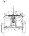
- Figure 2 shows a front view of the floor treating machine according to figure 1 .
- Figure 3 shows a view in perspective of a part of the floor treating machine according to the figures 1 and 2 .
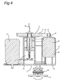
- Figure 4 shows a side view of a part of a second embodiment of the floor treating machine according to the invention.
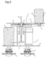
- Figure 5 shows a side view of a third embodiment of the floor treating machine according to the invention.
- the floor treating machine as shown in figures 1-3 comprises a carriage 1, which comprises legs 2, 3 which are interconnected by a crossbeam 4, as well as a frame 5 suspended from the crossbeam 4.
- a housing 6 is suspended from the frame 5, in such a way that it is rotatable with respect to vertical axis.
- the frame 5 comprises a downwardly extending rod 11, from which by means of rolling element bearings 7, 8 a tube 9 of wider diameter is suspended.
- This tube 9 is welded to a base plate 10, said tube 9 and the base plate 10 forming part of the housing 6 which through the bearings 7, 8 is rotatable with respect to the frame 5.
- each drive motor 12 On the upper side of the base plate 10, three drive motors 12 are mounted. Said drive motors can each comprise a housing 13, connected to the base plate 10, as well as a drive shaft 14 which freely protrudes through a corresponding hole in the base plate 10. As shown in figures 1 and 3 , a head 15 is connected to each shaft 14 by means of a damper 16. Thus, each head 15 is driven in rotation by means of its own drive motor 12.
- one of the drive motors 12 has a drive shaft 14 which extends at both ends out of the housing 12, the upper protruding end being indicated by reference numeral 17.
- a pulley wheel 18 of a relatively small diameter is mounted on said protruding upper end 17 of the drive shaft in question.
- a first auxiliary pulley wheel 19 of a relatively large diameter is rotatably mounted with respect to the housing on the beam 20;
- a second auxiliary pulley wheel 21 is fixedly and concentrically connected to the auxiliary pulley wheel 19 with a relatively large diameter.
- a fixed pulley wheel 22 with relatively large diameter is connected to the frame 5, in particular to an upper plate 23 thereof from which the rod 11 extends downwardly.
- a first auxiliary pulley 24 extends around the pulley wheel 18 mounted on the upper end 17 of the motor shaft 14 as well as around the auxiliary pulley wheel with relatively large diameter 19.
- a second auxiliary pulley 25 extends around the auxiliary pulley wheel 21 with a relatively small diameter, as well as around the fixed pulley wheel 22.
- the carriage 1 is furthermore provided with wheels 26, as well as a handle 27 for displacing the floor treating machine in question and for steering this.
- a sliding coupling 34 has been provided at the lower end of the rod 11.
- a further drive motor 28 is provided in addition to the drive motors 12 for the heads 15.
- the housing 29 of said further drive motor 28 is connected to the housing 6.
- the upwardly protruding shaft 30 of said drive motor 28 carries a pulley wheel 31 with a relatively small diameter.
- the frame 5 is provided with a fixed pulley wheel 32; around said pulley wheels 31,32 the pulley 33 extends.
- the embodiment of figure 5 comprises a further drive motor 28 the housing 29 of which is fixed to the plate 23 of the frame 5.
- the downwardly extending drive shaft 30 of said further drive motor 28 carries a pulley wheel 31 with a relatively small diameter, whereas the pulley wheel 32 with a relatively large diameter is connected to the frame 5.
- the housing 6 is brought into rotation with respect to the frame 6.
Landscapes
- Engineering & Computer Science (AREA)
- Mechanical Engineering (AREA)
- Finish Polishing, Edge Sharpening, And Grinding By Specific Grinding Devices (AREA)
- Grinding Of Cylindrical And Plane Surfaces (AREA)
- On-Site Construction Work That Accompanies The Preparation And Application Of Concrete (AREA)
- Cage And Drive Apparatuses For Elevators (AREA)
Applications Claiming Priority (1)
| Application Number | Priority Date | Filing Date | Title |
|---|---|---|---|
| US11/649,330 US7377838B1 (en) | 2007-01-03 | 2007-01-03 | Floor treating machine |
Publications (2)
| Publication Number | Publication Date |
|---|---|
| EP1941823A2 true EP1941823A2 (de) | 2008-07-09 |
| EP1941823A3 EP1941823A3 (de) | 2009-08-12 |
Family
ID=39226626
Family Applications (1)
| Application Number | Title | Priority Date | Filing Date |
|---|---|---|---|
| EP07124176A Withdrawn EP1941823A3 (de) | 2007-01-03 | 2007-12-31 | Bodenbearbeitungsmaschine |
Country Status (4)
| Country | Link |
|---|---|
| US (1) | US7377838B1 (de) |
| EP (1) | EP1941823A3 (de) |
| AU (1) | AU2008200026A1 (de) |
| CA (1) | CA2616741A1 (de) |
Cited By (13)
| Publication number | Priority date | Publication date | Assignee | Title |
|---|---|---|---|---|
| DE102008062746A1 (de) * | 2008-12-17 | 2010-06-24 | Holger Clasen Gmbh & Co. Kg | Großflächenschleifer |
| ITVI20110025A1 (it) * | 2011-02-11 | 2012-08-12 | Alba Paolo | Testa porta mole da montare su macchine levigatrici di materiali lapidei, quali marmo, granito e simili |
| JP2016007314A (ja) * | 2014-06-24 | 2016-01-18 | サマンサジャパン株式会社 | 床面洗浄装置,及び同床面洗浄装置を搭載した電動走行式床面洗浄機 |
| EP3524363A1 (de) * | 2018-02-07 | 2019-08-14 | The Boeing Company | Vorrichtungen und verfahren zur reinigung einer oberfläche |
| US10575628B2 (en) | 2018-02-07 | 2020-03-03 | The Boeing Company | Apparatuses for cleaning a surface |
| US10781029B2 (en) | 2017-12-21 | 2020-09-22 | The Boeing Company | Apparatuses for depositing an extrudable substance onto a surface |
| US10786939B2 (en) | 2017-12-21 | 2020-09-29 | The Boeing Company | Apparatuses for depositing an extrudable substance onto a surface |
| US10791825B2 (en) | 2017-12-21 | 2020-10-06 | The Boeing Company | Apparatuses for dispensing a brushable substance onto a surface |
| US10799910B2 (en) | 2017-12-21 | 2020-10-13 | The Boeing Company | Apparatuses for dispensing a brushable substance onto a surface |
| US10881192B2 (en) | 2018-02-07 | 2021-01-05 | The Boeing Company | Apparatuses and methods for cleaning a surface |
| WO2021034242A1 (en) | 2019-08-22 | 2021-02-25 | Husqvarna Ab | A drive arrangement for a floor surfacing machine and a floor surfacing machine |
| US10933435B2 (en) | 2017-12-21 | 2021-03-02 | The Boeing Company | Apparatuses for depositing an extrudable substance onto a surface |
| CN113829211A (zh) * | 2021-09-23 | 2021-12-24 | 浙江九树机械有限公司 | 一种压力容器的制造设备及其制造工艺 |
Families Citing this family (8)
| Publication number | Priority date | Publication date | Assignee | Title |
|---|---|---|---|---|
| US7815393B2 (en) * | 2007-07-25 | 2010-10-19 | Wagman Metal Products, Inc. | Mounting adapter for concrete surface processing tool |
| US7563156B2 (en) * | 2007-09-13 | 2009-07-21 | National Carpet Equipment, Inc. | Planetary grinder |
| US20110081847A1 (en) * | 2009-10-05 | 2011-04-07 | Tai-Her Yang | Motor parallel transmission portable angle grinder |
| US8485868B2 (en) * | 2009-12-07 | 2013-07-16 | Design Technologies Llc | Floor treatment apparatus with solitary drive pulley |
| US9289106B1 (en) * | 2014-10-23 | 2016-03-22 | Diamond Productions Ltd. | Floor treating machine head with flexible pad driver |
| US9744637B1 (en) * | 2015-03-01 | 2017-08-29 | Charles Lawhon | Floor processing system |
| EP3238878A1 (de) * | 2016-04-27 | 2017-11-01 | Guido Valentini | Handgehaltenes oder handgeführtes schleif- oder poliermaschinenwerkzeug |
| CN106584249B (zh) * | 2017-02-05 | 2019-05-14 | 太原市申海机械设备有限公司 | 一种圆盘抛光机 |
Citations (1)
| Publication number | Priority date | Publication date | Assignee | Title |
|---|---|---|---|---|
| US4719659A (en) | 1985-12-28 | 1988-01-19 | Uragami Fukashi | Rotary travelling surface treatment device |
Family Cites Families (7)
| Publication number | Priority date | Publication date | Assignee | Title |
|---|---|---|---|---|
| DE29812213U1 (de) * | 1998-07-09 | 1998-10-22 | Krauss, Ludwig, 57234 Wilnsdorf | Bodenschleifmaschine |
| US6238277B1 (en) * | 1999-05-27 | 2001-05-29 | C. Warren Duncan | Multidisc floor grinder |
| NL1015226C2 (nl) * | 2000-05-17 | 2001-11-22 | Holland Ind Diamantwerken Bv | Vloerbewerkingsmachine. |
| US7241210B2 (en) * | 2001-07-16 | 2007-07-10 | Holland Industriele Diamantwerken B.V. | Floor treating machine comprising individually driven discs |
| US6616517B2 (en) * | 2001-07-23 | 2003-09-09 | Onfloor Technologies, Llc | Wood floor sanding machine |
| US7226347B1 (en) * | 2006-01-09 | 2007-06-05 | Cpt, Inc. | Walk behind polisher |
| EP1806206B1 (de) * | 2006-01-10 | 2008-08-13 | Air-tec AG | Bodenschleifmaschine |
-
2007
- 2007-01-03 US US11/649,330 patent/US7377838B1/en not_active Expired - Fee Related
- 2007-12-31 EP EP07124176A patent/EP1941823A3/de not_active Withdrawn
-
2008
- 2008-01-02 AU AU2008200026A patent/AU2008200026A1/en not_active Abandoned
- 2008-01-02 CA CA002616741A patent/CA2616741A1/en not_active Abandoned
Patent Citations (1)
| Publication number | Priority date | Publication date | Assignee | Title |
|---|---|---|---|---|
| US4719659A (en) | 1985-12-28 | 1988-01-19 | Uragami Fukashi | Rotary travelling surface treatment device |
Cited By (24)
| Publication number | Priority date | Publication date | Assignee | Title |
|---|---|---|---|---|
| DE102008062746A1 (de) * | 2008-12-17 | 2010-06-24 | Holger Clasen Gmbh & Co. Kg | Großflächenschleifer |
| ITVI20110025A1 (it) * | 2011-02-11 | 2012-08-12 | Alba Paolo | Testa porta mole da montare su macchine levigatrici di materiali lapidei, quali marmo, granito e simili |
| JP2016007314A (ja) * | 2014-06-24 | 2016-01-18 | サマンサジャパン株式会社 | 床面洗浄装置,及び同床面洗浄装置を搭載した電動走行式床面洗浄機 |
| US11286100B2 (en) | 2017-12-21 | 2022-03-29 | The Boeing Company | Methods for depositing an extrudable substance onto a surface |
| US10933435B2 (en) | 2017-12-21 | 2021-03-02 | The Boeing Company | Apparatuses for depositing an extrudable substance onto a surface |
| US11896996B2 (en) | 2017-12-21 | 2024-02-13 | The Boeing Company | Methods for depositing an extrudable substance onto a surface |
| US10781029B2 (en) | 2017-12-21 | 2020-09-22 | The Boeing Company | Apparatuses for depositing an extrudable substance onto a surface |
| US10786939B2 (en) | 2017-12-21 | 2020-09-29 | The Boeing Company | Apparatuses for depositing an extrudable substance onto a surface |
| US10791825B2 (en) | 2017-12-21 | 2020-10-06 | The Boeing Company | Apparatuses for dispensing a brushable substance onto a surface |
| US10799910B2 (en) | 2017-12-21 | 2020-10-13 | The Boeing Company | Apparatuses for dispensing a brushable substance onto a surface |
| US11279073B2 (en) | 2017-12-21 | 2022-03-22 | The Boeing Company | Methods for depositing an extrudable substance onto a surface |
| US11278930B2 (en) | 2017-12-21 | 2022-03-22 | The Boeing Company | Methods for dispensing a brushable substance onto a surface |
| US11278110B2 (en) | 2017-12-21 | 2022-03-22 | The Boeing Company | Methods for dispensing a brushable substance onto a surface |
| US11678737B2 (en) | 2018-02-07 | 2023-06-20 | The Boeing Company | Methods for cleaning a surface |
| US10905228B2 (en) | 2018-02-07 | 2021-02-02 | The Boeing Company | Apparatuses for cleaning a surface |
| US10881192B2 (en) | 2018-02-07 | 2021-01-05 | The Boeing Company | Apparatuses and methods for cleaning a surface |
| EP3524363A1 (de) * | 2018-02-07 | 2019-08-14 | The Boeing Company | Vorrichtungen und verfahren zur reinigung einer oberfläche |
| JP2019171363A (ja) * | 2018-02-07 | 2019-10-10 | ザ・ボーイング・カンパニーThe Boeing Company | 表面を洗浄するための装置及び方法 |
| US11844420B2 (en) | 2018-02-07 | 2023-12-19 | The Boeing Company | Methods for cleaning a surface |
| US10575628B2 (en) | 2018-02-07 | 2020-03-03 | The Boeing Company | Apparatuses for cleaning a surface |
| WO2021034242A1 (en) | 2019-08-22 | 2021-02-25 | Husqvarna Ab | A drive arrangement for a floor surfacing machine and a floor surfacing machine |
| EP4364631A2 (de) | 2019-08-22 | 2024-05-08 | Husqvarna AB | Radträgeranordnung für eine bodenbearbeitungsmaschine |
| US12269143B2 (en) | 2019-08-22 | 2025-04-08 | Husqvarna Ab | Drive arrangement for a floor surfacing machine and a floor surfacing machine |
| CN113829211A (zh) * | 2021-09-23 | 2021-12-24 | 浙江九树机械有限公司 | 一种压力容器的制造设备及其制造工艺 |
Also Published As
| Publication number | Publication date |
|---|---|
| CA2616741A1 (en) | 2008-07-03 |
| AU2008200026A1 (en) | 2008-07-17 |
| EP1941823A3 (de) | 2009-08-12 |
| US7377838B1 (en) | 2008-05-27 |
Similar Documents
| Publication | Publication Date | Title |
|---|---|---|
| CA2616741A1 (en) | Floor treating machine | |
| CA2950857C (en) | Offset mounting adapter for concrete surface processing tool | |
| US6202775B1 (en) | Rotary floor finisher for use with a power rider trailer | |
| CN115533633B (zh) | 阀门密封面堆焊打磨装置 | |
| JP2019033804A (ja) | 床面洗浄装置 | |
| US2124705A (en) | Surfacing machine | |
| CN113478234A (zh) | 一种具有旋切功能的建筑工程用管道切割设备 | |
| CN205290558U (zh) | 一种刀剑制刃机 | |
| CN207981698U (zh) | 一种深孔清洗装置 | |
| CN108908032A (zh) | 一种磨削均匀的外圆磨床 | |
| KR20220056383A (ko) | 회전 작업대 | |
| KR102156391B1 (ko) | 타이어 외륜의 부착물 제거장치 | |
| CN210081329U (zh) | 一种易于调控的曲轴加工用磨削装置 | |
| CN113814878B (zh) | 一种槽式熨平机加热槽抛光装置 | |
| CN212371816U (zh) | 一种履带板打磨系统 | |
| CN216830218U (zh) | 一种机械配件用表面打磨装置 | |
| CN213004406U (zh) | 一种鱼竿把手的磨削加工装置 | |
| JP4245987B2 (ja) | 研削加工装置 | |
| CN218556467U (zh) | 一种圆棒钢锭表面砂轮自动抛磨装置的旋转和进给机构 | |
| CN223235582U (zh) | 一种可调式离心机用装配装置 | |
| CN209922771U (zh) | 一种电力工程布线用绞磨机 | |
| KR100600074B1 (ko) | 정화조 제조용 회전지그장치 | |
| CN222741113U (zh) | 一种换向器用换向片的自动砂倒抛装置 | |
| CN216830180U (zh) | 一种便于移动的打磨机 | |
| CN214817425U (zh) | 一种电极修磨机的可调节升降装置 |
Legal Events
| Date | Code | Title | Description |
|---|---|---|---|
| PUAI | Public reference made under article 153(3) epc to a published international application that has entered the european phase |
Free format text: ORIGINAL CODE: 0009012 |
|
| AK | Designated contracting states |
Kind code of ref document: A2 Designated state(s): AT BE BG CH CY CZ DE DK EE ES FI FR GB GR HU IE IS IT LI LT LU LV MC MT NL PL PT RO SE SI SK TR |
|
| AX | Request for extension of the european patent |
Extension state: AL BA HR MK RS |
|
| PUAL | Search report despatched |
Free format text: ORIGINAL CODE: 0009013 |
|
| AK | Designated contracting states |
Kind code of ref document: A3 Designated state(s): AT BE BG CH CY CZ DE DK EE ES FI FR GB GR HU IE IS IT LI LT LU LV MC MT NL PL PT RO SE SI SK TR |
|
| AX | Request for extension of the european patent |
Extension state: AL BA HR MK RS |
|
| AKX | Designation fees paid | ||
| REG | Reference to a national code |
Ref country code: DE Ref legal event code: 8566 |
|
| STAA | Information on the status of an ep patent application or granted ep patent |
Free format text: STATUS: THE APPLICATION IS DEEMED TO BE WITHDRAWN |
|
| 18D | Application deemed to be withdrawn |
Effective date: 20100213 |