EP1941785B1 - Farbbeleuchtungsvorrichtung - Google Patents
Farbbeleuchtungsvorrichtung Download PDFInfo
- Publication number
- EP1941785B1 EP1941785B1 EP06809540A EP06809540A EP1941785B1 EP 1941785 B1 EP1941785 B1 EP 1941785B1 EP 06809540 A EP06809540 A EP 06809540A EP 06809540 A EP06809540 A EP 06809540A EP 1941785 B1 EP1941785 B1 EP 1941785B1
- Authority
- EP
- European Patent Office
- Prior art keywords
- light
- lighting device
- photosensor
- output
- color
- Prior art date
- Legal status (The legal status is an assumption and is not a legal conclusion. Google has not performed a legal analysis and makes no representation as to the accuracy of the status listed.)
- Not-in-force
Links
Images
Classifications
-
- H—ELECTRICITY
- H05—ELECTRIC TECHNIQUES NOT OTHERWISE PROVIDED FOR
- H05B—ELECTRIC HEATING; ELECTRIC LIGHT SOURCES NOT OTHERWISE PROVIDED FOR; CIRCUIT ARRANGEMENTS FOR ELECTRIC LIGHT SOURCES, IN GENERAL
- H05B45/00—Circuit arrangements for operating light-emitting diodes [LED]
- H05B45/20—Controlling the colour of the light
- H05B45/22—Controlling the colour of the light using optical feedback
-
- F—MECHANICAL ENGINEERING; LIGHTING; HEATING; WEAPONS; BLASTING
- F21—LIGHTING
- F21Y—INDEXING SCHEME ASSOCIATED WITH SUBCLASSES F21K, F21L, F21S and F21V, RELATING TO THE FORM OR THE KIND OF THE LIGHT SOURCES OR OF THE COLOUR OF THE LIGHT EMITTED
- F21Y2115/00—Light-generating elements of semiconductor light sources
- F21Y2115/10—Light-emitting diodes [LED]
Definitions
- the invention relates to a color lighting device comprising a plurality of light-emitting sources fixed on a common substrate, wherein each light-emitting source comprises at least one light-emitting diode (LED).
- each light-emitting source comprises at least one light-emitting diode (LED).
- LEDs of different colors are used for constructing a lighting device that ghenerates a wide range of colors. These LEDs define an area in the CIE xy-color-space which shows the color that can be realized by the weighted linear combination of these LEDs (e.g. red(R), green(G) and blue(B)).
- the dissipated power will lead to a temperature increase of the dies close to 200°C. At this temperature the emission spectrum of the LEDs shifts in an unacceptable way.
- One of the disadvantages is that the shift is noticed by the human eyes.
- Red and green LEDs are known which are made of blue LEDs with a phosphor-ceramic layer on the top of the dies. Nevertheless, the intensity is still a function of the temperature, the current, and the lifetime. It is known that RGB-sensors can be used to control the color point. A considerable disadvantage of this approach is that these RGB-sensors are currently expensive and will suffer from their temperature dependency. Thus, one of the basic problems of known color lighting devices with color point control systems is that the sensor for color sensing has to fit the CIE color-matching functions. There are several commercial RGB-sensors available that claim to be close to the CIE color-matching functions, but none of these is sufficiently close to the CIE color-matching functions for the color control task.
- RGB-sensors degrade at elevated temperatures.
- Another disadvantage of color lighting devices with color point control systems is that the spectral insensitivity has to be independent of the temperature, which is not the case for normal photodiodes. Anyhow, these sensors are specified for temperature ranges, e.g. up to 85°C, which is at some distance to the above-mentioned temperature.
- color lighting devices comprise a control circuit with pulse width modulation (PWM), which controls the light output or the color of each single diode of the color lighting device.
- PWM pulse width modulation
- One of the disadvantages is that said color point control systems with pulse width modulation require very precise, complex and expensive components.
- PWM controlled multi-color lighting devices drive the LED in a very inefficient point if less than 100 % of the maximum brightness is used (which is typically the case). In some cases it is possible that electromagnetic interaction with the environment occurs due to the high-frequency current components (required for accurate PWM).
- US 2002/0130326 A I describes a lighting device comprising a plurality of LEDs that are arranged in an at least two-dimensionally dispersed manner, a transparent resin layer that covers the plurality of LEDs in an integrated form, a photodetection unit using a photodetector that detects a light emission intensity from the plurality of LEDs, a power supply circuit unit that controls driving of the plurality of the LEDs based on a detection output from the photo-detection unit, wherein a number of the photodetectors is smaller than the number of LEDs, and the photodetector detects an intensity of light emitted from the LEDs and propagated through the transparent resin layer.
- the LEDs for different colors are turned on with mutually different timings.
- the photodetector can thus only detect the light intensity sequentially for each color.
- the EP 1 152 642 A2 discloses a method an a apparatus for measuring spectral content of LED light sources, wherein photosensors are interspersed between the LED light sources to collect averaged and scattered light.
- the EP 1 077 444 A2 discloses a system and a method for an on-chip calibration of illumination sources of a display with a photo detector and an intensity sense and control circuit adjusting the intensity of the illumination source.
- the invention has for its object to eliminate the above disadvantages.
- a color lighting device comprising at least one light-emitting source fixed on a common substrate, each light-emitting source comprisisng at least one light-emitting diode (LED), each light-emitting source comprising one photosensor, arranged on the substrate adjacent to said light-emitting source, that detects the light output only of the associated light-emitting source, and each light-emitting source being connected to an analog control circuit that controls the drive of each light-emitting source separately on the basis of a light output detected by the associated photosensor, while each control circuit comprises a comparator connected to the associated photosensor.
- the control circuit controlling the color of the multi-color lighting device comprises a pure analog setup.
- the color lighting device consists of light-emitting sources which emit blue light, the peak wavelength being in the range from 420 to 470 nm, red light with the peak wavelength being in the range from 590 to 630 nm, and green light with a peak wavelength being in the range from 510 to 550 nm.
- the light-emitting source emits invisible light, which may be ultraviolet light.
- the light source may comprise only a single diode producing light of a defined color.
- the light source may comprise a plurality of LEDs together producing light of a certain color which issues from the lighting device.
- each LED may emit light with an individual peak wavelength. This means that each light source may comprise a bundle of LEDs, each LED emitting light of a different color.
- the device consists of a plurality of n light sources that emit light, wherein each light-emitting source is separately driven by a single driver line.
- the light-emitting source may consist of a mixture of small, e.g. GaN LEDs or broad-band emitters, e.g. phosphor-converted LEDs.
- the analog control circuit controls all light-emitting sources simultaneously in order to keep the optical output from the lighting device constant for a long time.
- Each light-emitting source comprises an individual photosensor that detects the light output of said source. Every single photosensor is arranged in the color lighting device in such a manner that only the emitted light of the source is measured by the associated photosensor. Thus, high-quality information on the actual light output of each single light source can be obtained.
- the control circuit comprises an analog two-point control system.
- Each photosensor detects a photo signal containing the information on the actual light output of the associated light source. Preferably, this signal is amplified and translated into an input for an analog comparator, where it is compared with a reference signal.
- the control circuit If the photosignal is less than the reference signal, the control circuit provides a high output-signal and if the photosignal is greater than the reference signal, the control circuit provides a low output-signal. If the two values of said signals are nearly equal, a low output-signal can also be provided.
- the high output signal and the low output signal are fixed values stored in the color lighting device, which either increase or decrease the driving signal for the light-emitting source.
- the described two-point control has an easy setup and is even more efficient than a color control based on pulse width modulation. Moreover, the control procedure does not generate any flickering of the light output, because in the present invention the current through the light source is changed with very low speed for color adjustment purposes.
- the present invention is suitable for simultaneous use of e.g. phosphor-converted LEDs and narrow-band LEDs (GaN, AlGaAs, etc). Compared with the pulse width modulation used for light output control, the present multi-color lighting device requires a short current rise time.
- the comparator is an analog Schmitt trigger.
- the Schmitt trigger changes its output state when its input voltage level rises above a certain reference voltage.
- the output does not switch back automatically when the input voltage level sinks again unless a second, lower reference voltage threshold is crossed.
- This difference in threshold voltages results in a hysteresis.
- the hysteresis guards against noise that would otherwise cause a rapid switching back and forth between the two output states when the inputs are close to the threshold voltage.
- the hysteresis is adjusted with respect to the low-pass filter that ensures that frequencies below 400 Hz are impossible.
- the control circuit comprises a driver connected to the comparator, wherein the output of the driver is guided to a low-pass-filter connected to each light source.
- the driving signal is changed in that a current flowing through the corresponding light source is changed, thereby preventing a change in the light output.
- the optical output from the device can thus be kept constant for a long time.
- the driver is an amplifier or a switch.
- the Schmitt trigger jumps between the high and the low output signal, the driver output signal being filtered by the low-pass filter that smooths the driving signal to each light source.
- the photosensor is arranged on the substrate next or adjacent to the light source. It is possible that the photosensor is positioned between the light source and the substrate. In this case the light source is arranged on the photosensor. In another preferred embodiment, the substrate is arranged between the photosensor and the light source. That means that the photosensor is fixed at the opposite side of the substrate, where the light source is not positioned. A wave guide may be formed in the substrate between the light source and the photosensor in order to interconnect these two components. In a possible embodiment of the invention, the photosensor and/or the light source may be embedded in the substrate. Furthermore, the core of the substrate may be made of metal so as to diffuse and dissipate heat generated by each LED effectively. Alternatively, the substrate may be made of epoxy resin or may be a composite substrate made of epoxy resin mixed with alumina.
- the photosensor comprises a filter that is sensitive to the color of the associated light-source.
- Said filter may be an optical filter.
- the photosensor detects only the light output of the corresponding light source and is insensitive to other colors. Thus, overlapping areas are not generated.
- each photosensor with a filter has a constant sensitivity over the wavelength range of interest for the applied colors.
- the filter response may be constant over a small wavelength regime.
- a filter response may have a very narrow band for phosphor-converted LEDs with a smooth response in the wavelength range of the peak sensitivity of the filtered-photosensor.
- the filters allow light in the wavelength ranges corresponding to those emitted by the respective light sources to pass through, so that the photosensor that deals with the respective luminescent colors is provided with a specific sensitivity to a certain light source.
- the filters are constructed such that their spectral transmissivities are adjusted to light that conforms with the peak wavelengths of the corresponding colors of light of the respective associated light sources.
- the filter comprises at least one layer that is e.g. placed on the photosensor.
- the photosensor may be a silicon photodiode with dielectric layers on top in order to achieve the required spectral sensitivity of the filtered photodiode.
- the filter comprises a plurality of conductive layers.
- a constant response can be achieved by using a narrow-band filter with different responses on top of each photosensor, e.g. a Fabry-Perot filter.
- the present invention also relates to a method of controlling the light output of a color lighting device with at least one light-emitting source fixed on a common substrate, each light-emitting source comprising at least one light-emitting diode, each light-emitting source comprising one photosensor, arranged on the substrate adjacent to said light-emitting source, that detects the light output only of the associated light-emitting source, and each light-emitting source being connected to an analog control circuit that controls the drive of each light-emitting source separately on the basis of a light output detected by the associated photosensor, while each control circuit comprises a comparator connected to the associated photosensor, said method comprising the following steps for color control: First, a photosignal is detected, which comprises the information on the actual light output of the single light source.
- the photosignal is guided to the control circuit, where the comparator compares the photosignal with a reference signal, the control circuit providing a high output-signal that increases the driving signal for the light-emitting source if the photosignal is less than the reference signal. If the photosignal is greater than the reference signal, the control circuit provides a low output-signal that decreases the driving signal for the light-emitting source, where the control circuit comprises a driver connected to the comparator, wherein the output of the driver is guided to a low-pass-filter connected to the light source, the value of the low output signal being zero. If the photosignal is greater than the reference signal, the value of the low output signal is zero.
- the low-pass filter has a cut-off frequency of at least 10kHz, making for a slow control circuit.
- the frequency determines the maximum rise time of the light source. If the user requires a higher rise time, the cut-off frequency can simply be increased.
- the combination of low-pass filter and comparator does not allow frequencies below 400 Hz.
- the described steps of the control procedure may be performed continuously and/or simultaneously for each light source. Certainly, said steps can be conducted periodically during operation of the lighting device.
- the measured photosignals are stored in a memory of a color controller which comprises a CPU for running an algorithm to calculate, for example, the brightness of each light source.
- the photosignal and the reference signal are voltage signals or current signals.
- the Schmitt trigger compares the output voltage signal of the photosensor with the reference voltage signal. If the photovoltage signal is less than the reference voltage signal, the output voltage of the Schmitt trigger is switched to a high output voltage signal. If the photovoltage signal is greater than the reference voltage signal, the output voltage signal of the Schmitt trigger is switched to a low output voltage.
- the color lighting device as well as the method mentioned above can be used in a variety of systems, among them automotive systems, home lighting systems, backlighting systems for displays, ambient lighting systems, flashes for cameras (with adjustable color), or shop lighting systems.
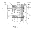
- FIG. 1 is a highly schematic view of a color lighting device according to one embodiment of the present invention.
- the color lighting device comprises a plurality of light-emitting sources 1a, 1b, 1c having a certain distance to each other.
- each light source 1a, 1b, 1c consists of a single LED 1a, 1b, 1c, i.e. the LED 1a, 1b, 1c is the light source 1a, 1b, 1c itself.
- each light source 1a, 1b, 1c may comprise a bundle of LEDs, which is not illustrated explicitly.
- Each LED 1a, 1b, 1c is mounted on a substrate 3 that constitutes a heat sink.
- Each LED 1a, 1b, 1c comprises an adjacent photosensor 2a, 2b, 2c which is also fixed on said substrate 3.
- Each light-emitting diode 1a, 1b, 1c is connected to a single analog control circuit 4a, 4b, 4c comprising a comparator 5a, 5b, 5c, a driver 6a, 6b, 6c, and a low-pass filter 7a, 7b, 7c.
- the comparator 5a, 5b, 5c is an analog Schmitt trigger connected to the associated photosensor 2a, 2b, 2c via a related amplifier 12a, 12b, 12c.
- the reference signals are connected to a color controller interface 10 which translates the user input 11 into the reference signals.
- the control circuits 4a, 4b, 4c are connected in parallel for controlling the drive of each light-emitting diode 1a, 1b, 1c separately on the basis of a light output detected by the associated photosensor 2a, 2b, 2c.
- Each photosensor 2a, 2b, 2c comprises a matched filter 8a, 8b, 8c.
- the LED 1a emits red light
- the LED 1b emits green light
- the LED 1c emits blue light
- the color lighting device may contain more than the colors mentioned here, which are separately controlled via the analog control circuit 4a, 4b, 4c.
- A11 circuits 4a, 4b, 4c are electrically identical, and therefore the red circuit line 4a only will be described in the following.
- the photosensor 2a detects the light output of the associated red light source 1a.
- the photosensor 2a comprises said filter 8a, which transmits only the wavelength of the emitted light of the LED 1a. This means that the filtered photosensor 2a is insensitive to other colors.
- the measured photosignal is a voltage signal of the photosensor 2a, which is guided via amplifier 12a to the comparator 5a.
- the comparator 5a is a Schmitt trigger 5a which compares the voltage signal of the photosensor 2a with a reference voltage signal.
- the control circuit 4a If the photovoltage signal is less than the reference voltage signal, the control circuit 4a provides a high output signal which increases the driving signal of the light-emitting diode 1 a. If the photovoltage signal is substantially equal to or greater than the reference voltage signal, the control circuit 4a provides a low output-signal which decreases the driving signal for the light-emitting diode 1a. The output of the Schmitt trigger 5a thus jumps between two voltage values.
- the output of the Schmitt trigger 5a is connected to an amplifier 6a.
- the output of the amplifier 6a is applied to the low-pass filter 7a that is directly connected to the LED 1a.
- the low-pass filter 7a has a cut-off frequency of 10 kHz.
- the described lighting device with the arranged control circuit 4a, 4b, 4c for each LED 1a, 1b, 1c allows an independent and parallel light output sensing of each color of said lighting device.
- the use of an analog circuit 4a, 4b, 4c for each LED 1a, 1b, 1c, wherein the photosignal of the photosensor 2a, 2b, 2c is used as a feedback-signal, provides an inexpensive and easy setup. Complex components like analog digital converters and digital signal processors with software are not necessary for the described analog color point stabilization of the multi-lighting device.
- the high output voltage signal is approximately 5 V. This causes an increase in the driving current for the light-emitting diode 1a. If the photovoltage signal is greater than the reference voltage signal, the control circuit 4a provides a low, i.e. zero output voltage signal, which decreases the driving current for the light-emitting diode 1a. That means that the amplifier does not pass a current to the low-pass-filter 7a.
- the LEDs 1a, 1b, 1c and the photosensors 2a, 2b, 2c are covered by an optical element 9 which is made of a transparent material.
Claims (13)
- Farbbeleuchtungsvorrichtung, die Folgendes umfasst:- eine Anzahl Licht ausstrahlender Quellen (1a, 1b, 1c) unterschiedlicher Farben, vorgesehen auf einem gemeinsamen Träger (3), die je wenigstens eine Leuchtdiode (LED) (1a, 1b, 1c) aufweisen,
dadurch gekennzeichnet, dass- jede Licht ausstrahlende Quelle (1a, 1b, 1c) einen Lichtsensor (2a, 2b, 2c) aufweist, vorgesehen auf dem träger (3) neben der genannten Licht ausstrahlenden Quelle (1a, 1b, 1c), der die Lichtleistung nur der genannten Licht ausstrahlenden Quelle (1a, 1b, 1c) detektiert, und- jede Licht ausstrahlende Quelle (1a, 1b, 1c) mit einer analogen Steuerschaltung (4a, 4b, 4c) verbunden ist, die eine Vergleichsschaltung (5a, 5b, 5c) aufweist, die mit dem entsprechenden Lichtsensor verbunden ist, der die Steuerung jeder Licht ausstrahlenden Quelle (1a, 1b, 1c) einzeln steuert, und zwar auf Basis einer von dem entsprechenden Lichtsensor (2a, 2b, 2c) detektierten Lichtleistung zur Ermöglichung einer unabhängigen und parallelen Lichtleistungsregelung jeder Farbe der genannten Beleuchtungsvorrichtung, wobei das Ausgangssignal der Treiberschaltung einem mit jeder Lichtquelle (1a, 1b, 1c) verbundenen Tiefpassfilter zugeführt wird. - Farbbeleuchtungsvorrichtung nach Anspruch 1, dadurch gekennzeichnet, dass die Vergleichsschaltung (5a, 5b, 5c) eine analoge Schmitt-Triggerschaltung (5a, 5b, 5c) ist.
- Farbbeleuchtungsvorrichtung nach einem der vorstehenden Ansprüche, dadurch gekennzeichnet, dass die Treiberschaltung (6a, 6b, 6c) ein Verstärker oder ein Schalter ist.
- Farbbeleuchtungsvorrichtung nach einem der vorstehenden Ansprüche, dadurch gekennzeichnet, dass der Lichtsensor (2a, 2b, 2c) neben der Lichtquelle (1a, 1b, 1c) auf dem Träger (3) vorgesehen ist, oder der Lichtsensor (2a, 2b, 2c) befindet sind zwischen der Lichtquelle (1a, 1b, 1c) und dem träger (3), oder der Träger (3) ist zwischen dem Lichtsensor (2a, 2b, 2c) und der Lichtquelle (1a, 1b, 1c) vorgesehen.
- Farbbeleuchtungsvorrichtung nach einem der vorstehenden Ansprüche, dadurch gekennzeichnet, dass der Lichtsensor (2a, 2b, 2c) ein optisches Filter (8a, 8b, 8c) aufweist.
- Farbbeleuchtungsvorrichtung nach einem der vorstehenden Ansprüche, dadurch gekennzeichnet, dass das optische Filter (8a, 8b, 8c) wenigstens eine Schicht aufweist, die auf dem Lichtsensor (2a, 2b, 2c) vorgesehen ist.
- Farbbeleuchtungsvorrichtung nach einem der vorstehenden Ansprüche, dadurch gekennzeichnet, dass das optische Filter (8a, 8b, 8c) eine Anzahl Schichten aufweist, wobei es sich um dielektrische Schichten und/oder leitende Schichten handelt.
- Farbbeleuchtungsvorrichtung nach einem der vorstehenden Ansprüche, dadurch gekennzeichnet, dass das Filter (8a, 8b, 8c) nur für die Farbe des von der zugeordneten Lichtquelle (1a, 1b, 2c) erzeugten Lichtes empfindlich ist.
- Verfahren zum Steuern der Lichtleistung einer Farbbeleuchtungsvorrichtung nach Anspruch 1, wobei dieses Verfahren die nachfolgenden Verfahrensschritte umfasst:- das Detektieren eines Lichtsignals, das Information über die aktuelle Lichtleistung der einzelnen Lichtquelle (1a, 1b, 1c) enthält,- das Zuführen des Lichtsignals zu der Steuerschaltung (4a, 4b, 4c), in der die Vergleichsschaltung (5a, 5b, 5c) das Lichtsignal mit dem Bezugssignal vergleicht, wonach wenn das Lichtsignal kleiner ist als das Bezugssignal
die Steuerschaltung (4a, 4b, 4c) ein hohes Ausgangssignal liefert, das das Treibersignal für die Licht ausstrahlende Quelle (1a, 1b, 1c) steigert,
wenn das Lichtsignal größer ist als das Bezugssignal
die Steuerschaltung (4a, 4b, 4c) ein niedriges Ausgangssignal liefert, das das Treibersignal für die Licht ausstrahlende Quelle (1a, 1b, 1c) verringert, dadurch gekennzeichnet, dass die Steuerschaltung (4a, 4b, 4c) eine Treiberschaltung (6a, 6b, 6c) aufweist, die mit dem Computer (5a, 5b, 5c) verbunden ist, wobei das Ausgangssignal der Treiberschaltung (6a, 6b, 6c) einem Tiefpassfilter (7a, 7b, 7c) zugeführt wird, das mit der Lichtquelle (1a, 1b, 1c) verbunden ist, und dass der Wert des niedrigen Ausgangssignals Null ist. - Verfahren nach Anspruch 9, dadurch gekennzeichnet, dass die Kombination des Tiefpassfilters)7a, 7b, 7c() und der Vergleichsschaltung (5a, 5b, 5c) Frequenzen unter 400 Hz sperrt.
- Verfahren nach einem der vorstehenden Ansprüche 9 oder 10, dadurch gekennzeichnet, dass die Verfahrensschritte nach Anspruch 9 kontinuierlich durchgeführt werden.
- Verfahren nach einem der vorstehenden Ansprüche 9 oder 11, dadurch gekennzeichnet, dass das Lichtsignal und das Bezugssignal Spannungssignale oder Stromsignale sind.
- Verfahren nach einem der vorstehenden Ansprüche 9 bis 12, dadurch gekennzeichnet, dass die Verfahrensschritte nach Anspruch 9 für alle Licht ausstrahlenden Quellen (1a, 1b, 1c) gleichzeitig durchgeführt werden.
Priority Applications (1)
| Application Number | Priority Date | Filing Date | Title |
|---|---|---|---|
| EP06809540A EP1941785B1 (de) | 2005-10-19 | 2006-10-09 | Farbbeleuchtungsvorrichtung |
Applications Claiming Priority (3)
| Application Number | Priority Date | Filing Date | Title |
|---|---|---|---|
| EP05109702 | 2005-10-19 | ||
| PCT/IB2006/053689 WO2007046026A1 (en) | 2005-10-19 | 2006-10-09 | A color lighting device |
| EP06809540A EP1941785B1 (de) | 2005-10-19 | 2006-10-09 | Farbbeleuchtungsvorrichtung |
Publications (2)
| Publication Number | Publication Date |
|---|---|
| EP1941785A1 EP1941785A1 (de) | 2008-07-09 |
| EP1941785B1 true EP1941785B1 (de) | 2011-01-19 |
Family
ID=37709717
Family Applications (1)
| Application Number | Title | Priority Date | Filing Date |
|---|---|---|---|
| EP06809540A Not-in-force EP1941785B1 (de) | 2005-10-19 | 2006-10-09 | Farbbeleuchtungsvorrichtung |
Country Status (9)
| Country | Link |
|---|---|
| US (1) | US7709774B2 (de) |
| EP (1) | EP1941785B1 (de) |
| JP (1) | JP2009513011A (de) |
| KR (1) | KR20080070659A (de) |
| CN (1) | CN101292573A (de) |
| AT (1) | ATE496515T1 (de) |
| DE (1) | DE602006019760D1 (de) |
| TW (1) | TW200731861A (de) |
| WO (1) | WO2007046026A1 (de) |
Families Citing this family (27)
| Publication number | Priority date | Publication date | Assignee | Title |
|---|---|---|---|---|
| CN101421556A (zh) * | 2006-04-19 | 2009-04-29 | 夏普株式会社 | 照明装置和具备该照明装置的液晶显示装置 |
| EP2035745B1 (de) | 2006-05-31 | 2020-04-29 | IDEAL Industries Lighting LLC | Beleuchtungsvorrichtung mit farbsteuerung und beleuchtungsverfahren |
| GB2446410B (en) * | 2007-02-07 | 2011-07-13 | Signal House Ltd | Traffic signal light |
| JP5034719B2 (ja) * | 2007-07-04 | 2012-09-26 | 日亜化学工業株式会社 | 半導体発光装置 |
| US8829820B2 (en) | 2007-08-10 | 2014-09-09 | Cree, Inc. | Systems and methods for protecting display components from adverse operating conditions |
| US8866410B2 (en) | 2007-11-28 | 2014-10-21 | Cree, Inc. | Solid state lighting devices and methods of manufacturing the same |
| US8643308B2 (en) | 2009-08-14 | 2014-02-04 | Once Innovations, Inc. | Spectral shift control for dimmable AC LED lighting |
| US9380665B2 (en) | 2009-08-14 | 2016-06-28 | Once Innovations, Inc. | Spectral shift control for dimmable AC LED lighting |
| US9433046B2 (en) | 2011-01-21 | 2016-08-30 | Once Innovations, Inc. | Driving circuitry for LED lighting with reduced total harmonic distortion |
| US8373363B2 (en) | 2009-08-14 | 2013-02-12 | Once Innovations, Inc. | Reduction of harmonic distortion for LED loads |
| US9232590B2 (en) | 2009-08-14 | 2016-01-05 | Once Innovations, Inc. | Driving circuitry for LED lighting with reduced total harmonic distortion |
| US9482397B2 (en) | 2010-03-17 | 2016-11-01 | Once Innovations, Inc. | Light sources adapted to spectral sensitivity of diurnal avians and humans |
| DE102010041830A1 (de) * | 2010-09-30 | 2012-04-05 | Automotive Lighting Reutlingen Gmbh | Steuer- und Regeleinrichtung für eine Gasentladungslampe eines Kraftfahrzeugscheinwerfers |
| KR20120113419A (ko) * | 2011-04-05 | 2012-10-15 | 삼성전자주식회사 | 발광소자 모듈 및 면광원 장치 |
| CN102814005A (zh) * | 2011-05-13 | 2012-12-12 | 通用电气公司 | 在光疗装置中提供光的均匀分布的方法 |
| WO2013090708A1 (en) | 2011-12-14 | 2013-06-20 | Once Innovations Inc | Light emitting system with adjustable watt equivalence |
| US9167656B2 (en) * | 2012-05-04 | 2015-10-20 | Abl Ip Holding Llc | Lifetime correction for aging of LEDs in tunable-white LED lighting devices |
| US9255674B2 (en) | 2012-10-04 | 2016-02-09 | Once Innovations, Inc. | Method of manufacturing a light emitting diode lighting assembly |
| DE102013202282A1 (de) * | 2013-02-13 | 2014-08-14 | Continental Automotive Gmbh | Lichtquelle und Verfahren zur Herstellung der Lichtquelle |
| DE102013207525A1 (de) * | 2013-04-25 | 2014-10-30 | Zumtobel Lighting Gmbh | Verfahren und Schaltungsanordnung zum Betreiben einer LED-Lichtquelle |
| US10237956B2 (en) | 2013-08-02 | 2019-03-19 | Once Innovations, Inc. | System and method of illuminating livestock |
| US10206378B2 (en) | 2014-01-07 | 2019-02-19 | Once Innovations, Inc. | System and method of enhancing swine reproduction |
| US9247603B2 (en) * | 2014-02-11 | 2016-01-26 | Once Innovations, Inc. | Shunt regulator for spectral shift controlled light source |
| WO2015159676A1 (ja) | 2014-04-17 | 2015-10-22 | オリンパス株式会社 | 光源装置 |
| BR112018069831A2 (pt) | 2016-03-29 | 2019-01-29 | Once Innovations Inc | sistema de controle para iluminação de suínos e método de estimulação de uma resposta biológica em suínos |
| US10314125B2 (en) | 2016-09-30 | 2019-06-04 | Once Innovations, Inc. | Dimmable analog AC circuit |
| US11404610B2 (en) | 2019-05-22 | 2022-08-02 | Electronic Theatre Controls, Inc. | Light fixture with broadband and narrow band emitters |
Family Cites Families (22)
| Publication number | Priority date | Publication date | Assignee | Title |
|---|---|---|---|---|
| AU497359B2 (en) | 1974-11-27 | 1978-12-07 | Pyrotector, Incorporated | Photoelectric smoke detector |
| JPS6019313A (ja) * | 1983-07-13 | 1985-01-31 | Toshiba Corp | 高出力用集積回路の出力トランジスタ保護回路 |
| DE3473924D1 (en) * | 1983-10-03 | 1988-10-13 | Rsf Elektronik Gmbh | Optoelectronic length and angle metering method and measuring device to realize this method |
| JPH0526829Y2 (de) * | 1985-08-02 | 1993-07-07 | ||
| GB2204946A (en) | 1987-05-18 | 1988-11-23 | Stephen George Marland | Automatic vehicle light switch |
| US5296702A (en) * | 1992-07-28 | 1994-03-22 | Patchen California | Structure and method for differentiating one object from another object |
| JP4050802B2 (ja) * | 1996-08-02 | 2008-02-20 | シチズン電子株式会社 | カラー表示装置 |
| US6300612B1 (en) | 1998-02-02 | 2001-10-09 | Uniax Corporation | Image sensors made from organic semiconductors |
| US6344641B1 (en) | 1999-08-11 | 2002-02-05 | Agilent Technologies, Inc. | System and method for on-chip calibration of illumination sources for an integrated circuit display |
| US6448550B1 (en) | 2000-04-27 | 2002-09-10 | Agilent Technologies, Inc. | Method and apparatus for measuring spectral content of LED light source and control thereof |
| JP2002217872A (ja) * | 2001-01-19 | 2002-08-02 | Toshiba Electronic Engineering Corp | 光伝送装置 |
| US6611000B2 (en) * | 2001-03-14 | 2003-08-26 | Matsushita Electric Industrial Co., Ltd. | Lighting device |
| JP3795762B2 (ja) * | 2001-03-16 | 2006-07-12 | エヌティティエレクトロニクス株式会社 | 光出力制御回路 |
| US6507159B2 (en) * | 2001-03-29 | 2003-01-14 | Koninklijke Philips Electronics N.V. | Controlling method and system for RGB based LED luminary |
| JP3517409B2 (ja) * | 2001-12-20 | 2004-04-12 | サンテック株式会社 | 光信号分析装置 |
| JP2003188467A (ja) * | 2001-12-20 | 2003-07-04 | Mitsubishi Electric Corp | 光半導体モジュール |
| JP2003218459A (ja) * | 2002-01-22 | 2003-07-31 | Fujitsu Access Ltd | 光出力調整方法 |
| US6998594B2 (en) * | 2002-06-25 | 2006-02-14 | Koninklijke Philips Electronics N.V. | Method for maintaining light characteristics from a multi-chip LED package |
| US6930452B2 (en) * | 2002-10-14 | 2005-08-16 | Lumileds Lighting U.S., Llc | Circuit arrangement |
| US7026769B2 (en) | 2003-12-18 | 2006-04-11 | Joon Chok Lee | Luminary control system adapted for reproducing the color of a known light source |
| JP4352393B2 (ja) * | 2004-01-07 | 2009-10-28 | 横河電機株式会社 | 光源装置 |
| US7218656B2 (en) * | 2004-05-26 | 2007-05-15 | Avago Technologies Ecbu Ip (Singapore) Pte. Ltd. | Control of spectral content of a laser diode light source |
-
2006
- 2006-10-09 DE DE602006019760T patent/DE602006019760D1/de active Active
- 2006-10-09 US US12/090,874 patent/US7709774B2/en not_active Expired - Fee Related
- 2006-10-09 AT AT06809540T patent/ATE496515T1/de not_active IP Right Cessation
- 2006-10-09 WO PCT/IB2006/053689 patent/WO2007046026A1/en active Application Filing
- 2006-10-09 JP JP2008536163A patent/JP2009513011A/ja active Pending
- 2006-10-09 EP EP06809540A patent/EP1941785B1/de not_active Not-in-force
- 2006-10-09 KR KR1020087011644A patent/KR20080070659A/ko not_active Application Discontinuation
- 2006-10-09 CN CNA2006800389719A patent/CN101292573A/zh active Pending
- 2006-10-16 TW TW095138063A patent/TW200731861A/zh unknown
Also Published As
| Publication number | Publication date |
|---|---|
| ATE496515T1 (de) | 2011-02-15 |
| CN101292573A (zh) | 2008-10-22 |
| US7709774B2 (en) | 2010-05-04 |
| DE602006019760D1 (de) | 2011-03-03 |
| EP1941785A1 (de) | 2008-07-09 |
| WO2007046026A1 (en) | 2007-04-26 |
| JP2009513011A (ja) | 2009-03-26 |
| TW200731861A (en) | 2007-08-16 |
| KR20080070659A (ko) | 2008-07-30 |
| US20080290250A1 (en) | 2008-11-27 |
Similar Documents
| Publication | Publication Date | Title |
|---|---|---|
| EP1941785B1 (de) | Farbbeleuchtungsvorrichtung | |
| JP4185255B2 (ja) | Led光源のスペクトル内容の測定及び制御を行う方法及び装置 | |
| KR101212617B1 (ko) | 조명장치 및 그 제어 방법 | |
| KR101303367B1 (ko) | 컬러 포인트 제어 시스템 | |
| EP1878317B1 (de) | Beleuchtungssteuersystem für lichtemitter | |
| US7230222B2 (en) | Calibrated LED light module | |
| US7388665B2 (en) | Multicolour chromaticity sensor | |
| KR100916178B1 (ko) | 멀티칩 발광-다이오드 패키지 및 조사 디바이스 | |
| KR101106818B1 (ko) | 광원 및 장치 조명 방법 | |
| TWI587735B (zh) | 發光二極體組件、發光二極體固定件、控制方法及軟體程式 | |
| US10555394B2 (en) | Solid state lighting systems and associated methods of operation and manufacture | |
| CN100561393C (zh) | 激光二极管光学光源的光谱控制 | |
| US20200404756A1 (en) | Lighting device having an interim operable state | |
| US11272599B1 (en) | Calibration procedure for a light-emitting diode light source | |
| KR101694995B1 (ko) | 조명 장치 및 조명 장치의 제어 방법 |
Legal Events
| Date | Code | Title | Description |
|---|---|---|---|
| PUAI | Public reference made under article 153(3) epc to a published international application that has entered the european phase |
Free format text: ORIGINAL CODE: 0009012 |
|
| 17P | Request for examination filed |
Effective date: 20080519 |
|
| AK | Designated contracting states |
Kind code of ref document: A1 Designated state(s): AT BE BG CH CY CZ DE DK EE ES FI FR GB GR HU IE IS IT LI LT LU LV MC NL PL PT RO SE SI SK TR |
|
| 17Q | First examination report despatched |
Effective date: 20090402 |
|
| GRAP | Despatch of communication of intention to grant a patent |
Free format text: ORIGINAL CODE: EPIDOSNIGR1 |
|
| DAX | Request for extension of the european patent (deleted) | ||
| GRAS | Grant fee paid |
Free format text: ORIGINAL CODE: EPIDOSNIGR3 |
|
| GRAA | (expected) grant |
Free format text: ORIGINAL CODE: 0009210 |
|
| AK | Designated contracting states |
Kind code of ref document: B1 Designated state(s): AT BE BG CH CY CZ DE DK EE ES FI FR GB GR HU IE IS IT LI LT LU LV MC NL PL PT RO SE SI SK TR |
|
| REG | Reference to a national code |
Ref country code: GB Ref legal event code: FG4D |
|
| REG | Reference to a national code |
Ref country code: CH Ref legal event code: EP |
|
| REG | Reference to a national code |
Ref country code: IE Ref legal event code: FG4D |
|
| REF | Corresponds to: |
Ref document number: 602006019760 Country of ref document: DE Date of ref document: 20110303 Kind code of ref document: P |
|
| REG | Reference to a national code |
Ref country code: DE Ref legal event code: R096 Ref document number: 602006019760 Country of ref document: DE Effective date: 20110303 |
|
| REG | Reference to a national code |
Ref country code: NL Ref legal event code: VDEP Effective date: 20110119 |
|
| LTIE | Lt: invalidation of european patent or patent extension |
Effective date: 20110119 |
|
| PG25 | Lapsed in a contracting state [announced via postgrant information from national office to epo] |
Ref country code: IS Free format text: LAPSE BECAUSE OF FAILURE TO SUBMIT A TRANSLATION OF THE DESCRIPTION OR TO PAY THE FEE WITHIN THE PRESCRIBED TIME-LIMIT Effective date: 20110519 Ref country code: SE Free format text: LAPSE BECAUSE OF FAILURE TO SUBMIT A TRANSLATION OF THE DESCRIPTION OR TO PAY THE FEE WITHIN THE PRESCRIBED TIME-LIMIT Effective date: 20110119 Ref country code: LT Free format text: LAPSE BECAUSE OF FAILURE TO SUBMIT A TRANSLATION OF THE DESCRIPTION OR TO PAY THE FEE WITHIN THE PRESCRIBED TIME-LIMIT Effective date: 20110119 Ref country code: LV Free format text: LAPSE BECAUSE OF FAILURE TO SUBMIT A TRANSLATION OF THE DESCRIPTION OR TO PAY THE FEE WITHIN THE PRESCRIBED TIME-LIMIT Effective date: 20110119 Ref country code: GR Free format text: LAPSE BECAUSE OF FAILURE TO SUBMIT A TRANSLATION OF THE DESCRIPTION OR TO PAY THE FEE WITHIN THE PRESCRIBED TIME-LIMIT Effective date: 20110420 Ref country code: PT Free format text: LAPSE BECAUSE OF FAILURE TO SUBMIT A TRANSLATION OF THE DESCRIPTION OR TO PAY THE FEE WITHIN THE PRESCRIBED TIME-LIMIT Effective date: 20110519 Ref country code: ES Free format text: LAPSE BECAUSE OF FAILURE TO SUBMIT A TRANSLATION OF THE DESCRIPTION OR TO PAY THE FEE WITHIN THE PRESCRIBED TIME-LIMIT Effective date: 20110430 |
|
| PG25 | Lapsed in a contracting state [announced via postgrant information from national office to epo] |
Ref country code: BG Free format text: LAPSE BECAUSE OF FAILURE TO SUBMIT A TRANSLATION OF THE DESCRIPTION OR TO PAY THE FEE WITHIN THE PRESCRIBED TIME-LIMIT Effective date: 20110419 Ref country code: NL Free format text: LAPSE BECAUSE OF FAILURE TO SUBMIT A TRANSLATION OF THE DESCRIPTION OR TO PAY THE FEE WITHIN THE PRESCRIBED TIME-LIMIT Effective date: 20110119 Ref country code: AT Free format text: LAPSE BECAUSE OF FAILURE TO SUBMIT A TRANSLATION OF THE DESCRIPTION OR TO PAY THE FEE WITHIN THE PRESCRIBED TIME-LIMIT Effective date: 20110119 Ref country code: SI Free format text: LAPSE BECAUSE OF FAILURE TO SUBMIT A TRANSLATION OF THE DESCRIPTION OR TO PAY THE FEE WITHIN THE PRESCRIBED TIME-LIMIT Effective date: 20110119 Ref country code: BE Free format text: LAPSE BECAUSE OF FAILURE TO SUBMIT A TRANSLATION OF THE DESCRIPTION OR TO PAY THE FEE WITHIN THE PRESCRIBED TIME-LIMIT Effective date: 20110119 Ref country code: PL Free format text: LAPSE BECAUSE OF FAILURE TO SUBMIT A TRANSLATION OF THE DESCRIPTION OR TO PAY THE FEE WITHIN THE PRESCRIBED TIME-LIMIT Effective date: 20110119 Ref country code: CY Free format text: LAPSE BECAUSE OF FAILURE TO SUBMIT A TRANSLATION OF THE DESCRIPTION OR TO PAY THE FEE WITHIN THE PRESCRIBED TIME-LIMIT Effective date: 20110119 Ref country code: FI Free format text: LAPSE BECAUSE OF FAILURE TO SUBMIT A TRANSLATION OF THE DESCRIPTION OR TO PAY THE FEE WITHIN THE PRESCRIBED TIME-LIMIT Effective date: 20110119 |
|
| PG25 | Lapsed in a contracting state [announced via postgrant information from national office to epo] |
Ref country code: EE Free format text: LAPSE BECAUSE OF FAILURE TO SUBMIT A TRANSLATION OF THE DESCRIPTION OR TO PAY THE FEE WITHIN THE PRESCRIBED TIME-LIMIT Effective date: 20110119 Ref country code: DK Free format text: LAPSE BECAUSE OF FAILURE TO SUBMIT A TRANSLATION OF THE DESCRIPTION OR TO PAY THE FEE WITHIN THE PRESCRIBED TIME-LIMIT Effective date: 20110119 |
|
| PLBE | No opposition filed within time limit |
Free format text: ORIGINAL CODE: 0009261 |
|
| STAA | Information on the status of an ep patent application or granted ep patent |
Free format text: STATUS: NO OPPOSITION FILED WITHIN TIME LIMIT |
|
| PG25 | Lapsed in a contracting state [announced via postgrant information from national office to epo] |
Ref country code: SK Free format text: LAPSE BECAUSE OF FAILURE TO SUBMIT A TRANSLATION OF THE DESCRIPTION OR TO PAY THE FEE WITHIN THE PRESCRIBED TIME-LIMIT Effective date: 20110119 Ref country code: CZ Free format text: LAPSE BECAUSE OF FAILURE TO SUBMIT A TRANSLATION OF THE DESCRIPTION OR TO PAY THE FEE WITHIN THE PRESCRIBED TIME-LIMIT Effective date: 20110119 Ref country code: RO Free format text: LAPSE BECAUSE OF FAILURE TO SUBMIT A TRANSLATION OF THE DESCRIPTION OR TO PAY THE FEE WITHIN THE PRESCRIBED TIME-LIMIT Effective date: 20110119 |
|
| 26N | No opposition filed |
Effective date: 20111020 |
|
| PG25 | Lapsed in a contracting state [announced via postgrant information from national office to epo] |
Ref country code: IT Free format text: LAPSE BECAUSE OF FAILURE TO SUBMIT A TRANSLATION OF THE DESCRIPTION OR TO PAY THE FEE WITHIN THE PRESCRIBED TIME-LIMIT Effective date: 20110119 |
|
| REG | Reference to a national code |
Ref country code: DE Ref legal event code: R097 Ref document number: 602006019760 Country of ref document: DE Effective date: 20111020 |
|
| PG25 | Lapsed in a contracting state [announced via postgrant information from national office to epo] |
Ref country code: MC Free format text: LAPSE BECAUSE OF NON-PAYMENT OF DUE FEES Effective date: 20111031 |
|
| REG | Reference to a national code |
Ref country code: CH Ref legal event code: PL |
|
| PG25 | Lapsed in a contracting state [announced via postgrant information from national office to epo] |
Ref country code: CH Free format text: LAPSE BECAUSE OF NON-PAYMENT OF DUE FEES Effective date: 20111031 Ref country code: LI Free format text: LAPSE BECAUSE OF NON-PAYMENT OF DUE FEES Effective date: 20111031 |
|
| REG | Reference to a national code |
Ref country code: IE Ref legal event code: MM4A |
|
| REG | Reference to a national code |
Ref country code: AT Ref legal event code: MK05 Ref document number: 496515 Country of ref document: AT Kind code of ref document: T Effective date: 20110119 |
|
| PG25 | Lapsed in a contracting state [announced via postgrant information from national office to epo] |
Ref country code: IE Free format text: LAPSE BECAUSE OF NON-PAYMENT OF DUE FEES Effective date: 20111009 |
|
| PGFP | Annual fee paid to national office [announced via postgrant information from national office to epo] |
Ref country code: FR Payment date: 20121128 Year of fee payment: 7 |
|
| PGFP | Annual fee paid to national office [announced via postgrant information from national office to epo] |
Ref country code: GB Payment date: 20121031 Year of fee payment: 7 |
|
| PGFP | Annual fee paid to national office [announced via postgrant information from national office to epo] |
Ref country code: DE Payment date: 20121228 Year of fee payment: 7 |
|
| PG25 | Lapsed in a contracting state [announced via postgrant information from national office to epo] |
Ref country code: LU Free format text: LAPSE BECAUSE OF NON-PAYMENT OF DUE FEES Effective date: 20111009 |
|
| PG25 | Lapsed in a contracting state [announced via postgrant information from national office to epo] |
Ref country code: TR Free format text: LAPSE BECAUSE OF FAILURE TO SUBMIT A TRANSLATION OF THE DESCRIPTION OR TO PAY THE FEE WITHIN THE PRESCRIBED TIME-LIMIT Effective date: 20110119 |
|
| PG25 | Lapsed in a contracting state [announced via postgrant information from national office to epo] |
Ref country code: HU Free format text: LAPSE BECAUSE OF FAILURE TO SUBMIT A TRANSLATION OF THE DESCRIPTION OR TO PAY THE FEE WITHIN THE PRESCRIBED TIME-LIMIT Effective date: 20110119 |
|
| REG | Reference to a national code |
Ref country code: DE Ref legal event code: R081 Ref document number: 602006019760 Country of ref document: DE Owner name: PHILIPS DEUTSCHLAND GMBH, DE Free format text: FORMER OWNER: PHILIPS INTELLECTUAL PROPERTY & STANDARDS GMBH, 20099 HAMBURG, DE Effective date: 20140331 |
|
| GBPC | Gb: european patent ceased through non-payment of renewal fee |
Effective date: 20131009 |
|
| PG25 | Lapsed in a contracting state [announced via postgrant information from national office to epo] |
Ref country code: GB Free format text: LAPSE BECAUSE OF NON-PAYMENT OF DUE FEES Effective date: 20131009 |
|
| REG | Reference to a national code |
Ref country code: DE Ref legal event code: R119 Ref document number: 602006019760 Country of ref document: DE Effective date: 20140501 |
|
| REG | Reference to a national code |
Ref country code: FR Ref legal event code: ST Effective date: 20140630 |
|
| PG25 | Lapsed in a contracting state [announced via postgrant information from national office to epo] |
Ref country code: FR Free format text: LAPSE BECAUSE OF NON-PAYMENT OF DUE FEES Effective date: 20131031 Ref country code: DE Free format text: LAPSE BECAUSE OF NON-PAYMENT OF DUE FEES Effective date: 20140501 |