EP1941283B1 - Labor-roboter-anordnung - Google Patents
Labor-roboter-anordnung Download PDFInfo
- Publication number
- EP1941283B1 EP1941283B1 EP06792332A EP06792332A EP1941283B1 EP 1941283 B1 EP1941283 B1 EP 1941283B1 EP 06792332 A EP06792332 A EP 06792332A EP 06792332 A EP06792332 A EP 06792332A EP 1941283 B1 EP1941283 B1 EP 1941283B1
- Authority
- EP
- European Patent Office
- Prior art keywords
- module
- pipetting
- robot
- robot system
- axis arm
- Prior art date
- Legal status (The legal status is an assumption and is not a legal conclusion. Google has not performed a legal analysis and makes no representation as to the accuracy of the status listed.)
- Not-in-force
Links
Images



Classifications
-
- B—PERFORMING OPERATIONS; TRANSPORTING
- B01—PHYSICAL OR CHEMICAL PROCESSES OR APPARATUS IN GENERAL
- B01L—CHEMICAL OR PHYSICAL LABORATORY APPARATUS FOR GENERAL USE
- B01L3/00—Containers or dishes for laboratory use, e.g. laboratory glassware; Droppers
- B01L3/02—Burettes; Pipettes
- B01L3/021—Pipettes, i.e. with only one conduit for withdrawing and redistributing liquids
- B01L3/0217—Pipettes, i.e. with only one conduit for withdrawing and redistributing liquids of the plunger pump type
-
- B—PERFORMING OPERATIONS; TRANSPORTING
- B25—HAND TOOLS; PORTABLE POWER-DRIVEN TOOLS; MANIPULATORS
- B25J—MANIPULATORS; CHAMBERS PROVIDED WITH MANIPULATION DEVICES
- B25J9/00—Program-controlled manipulators
- B25J9/02—Program-controlled manipulators characterised by movement of the arms, e.g. cartesian coordinate type
- B25J9/023—Cartesian coordinate type
-
- G—PHYSICS
- G01—MEASURING; TESTING
- G01N—INVESTIGATING OR ANALYSING MATERIALS BY DETERMINING THEIR CHEMICAL OR PHYSICAL PROPERTIES
- G01N35/00—Automatic analysis not limited to methods or materials provided for in any single one of groups G01N1/00 - G01N33/00; Handling materials therefor
- G01N35/0099—Automatic analysis not limited to methods or materials provided for in any single one of groups G01N1/00 - G01N33/00; Handling materials therefor comprising robots or similar manipulators
-
- B—PERFORMING OPERATIONS; TRANSPORTING
- B01—PHYSICAL OR CHEMICAL PROCESSES OR APPARATUS IN GENERAL
- B01L—CHEMICAL OR PHYSICAL LABORATORY APPARATUS FOR GENERAL USE
- B01L2200/00—Solutions for specific problems relating to chemical or physical laboratory apparatus
- B01L2200/02—Adapting objects or devices to another
- B01L2200/021—Adjust spacings in an array of wells, pipettes or holders, format transfer between arrays of different size or geometry
- B01L2200/022—Variable spacings
-
- B—PERFORMING OPERATIONS; TRANSPORTING
- B01—PHYSICAL OR CHEMICAL PROCESSES OR APPARATUS IN GENERAL
- B01L—CHEMICAL OR PHYSICAL LABORATORY APPARATUS FOR GENERAL USE
- B01L2200/00—Solutions for specific problems relating to chemical or physical laboratory apparatus
- B01L2200/02—Adapting objects or devices to another
- B01L2200/025—Align devices or objects to ensure defined positions relative to each other
-
- G—PHYSICS
- G01—MEASURING; TESTING
- G01N—INVESTIGATING OR ANALYSING MATERIALS BY DETERMINING THEIR CHEMICAL OR PHYSICAL PROPERTIES
- G01N35/00—Automatic analysis not limited to methods or materials provided for in any single one of groups G01N1/00 - G01N33/00; Handling materials therefor
- G01N35/10—Devices for transferring samples or any liquids to, in, or from, the analysis apparatus, e.g. suction devices, injection devices
- G01N35/1065—Multiple transfer devices
- G01N2035/1076—Multiple transfer devices plurality or independently movable heads
Definitions
- the invention relates to a laboratory robot arrangement for the life sciences sector, comprising at least a first robot module with an X-axis arm, on which at least one Y-axis arm is movably arranged in the X direction.
- this object is achieved in an equally surprising and effective manner with a robot arrangement according to claim 1.
- the robot assembly may be equipped with a connection to a storage system.
- a movable in the Y direction coupling device is provided for coupling a working module.
- the robot assembly is therefore characterized by a high degree of modularity.
- adjacent robot modules can be connected to one another.
- the connection can be designed as a latching and / or plug connection.
- Adjacent X-axis arms can thereby be connected to a common X-axis arm and / or held in abutment with each other.
- the robot modules are particularly easy to use and manageable when they are designed as a tabletop device. If larger robot arrangements are required, several robot modules can be simply strung together.
- At least two Y-axis arms can be provided on at least one robot module.
- a pipetting module may be provided on a first Y-axis arm and a gripper module on a second Y-axis arm.
- samples can be taken from containers and samples or containers can be exchanged by the gripper module.
- the working module is movable in Z-direction.
- it is preferably designed as a Z-axis arm or comprises a Z-axis arm.
- the Anköppet is movable and driven relative to the Y-axis arm in the Z direction.
- a working module such as a pipetting module or a gripper module
- a Z-axis arm can be provided on the working module to be coupled, which allows a movement of the (remaining) working module relative to the Y-axis arm in the Z direction.
- both Y-axis arms have at least one coupling device. Thereby can even more different or similar work modules are coupled and used. The modularity and the area of use are thereby further increased or increased.
- At least one Y-axis arm has two coupling devices.
- the coupling devices are independently movable in the Y direction. It is particularly preferred if, viewed in the X direction, they are arranged on different sides of the Y-axis arm and can be driven individually.
- the coupling device has connections, in particular an electrical connection and / or data connection, for the working module to be coupled.
- connections in particular an electrical connection and / or data connection
- Different measures can be provided in order to fix the working module to the coupling device.
- the working module can be flanged.
- it can also be provided a latching connection or a bayonet-type closure.
- connections to the rest of the robot assembly or to the robot module must be made.
- the working module can be supplied with electrical energy via the robot module.
- a data exchange of the working module with a control device of the robot module or the robot assembly is possible.
- the corresponding connections are made automatically when coupling the working module to the coupling device.
- further connections for example a pneumatic connection or a hydraulic connection, can be provided.
- the robot module preferably has a data bus, for example a CAN bus or Interbus. Therefore, it is convenient if the data port is designed as a bus connection, in particular as an interface to a CAN bus or Interbus.
- the relative movement of the Y-axis arm with respect to the X-axis arm and the coupling devices with respect to the Y-axis arm is preferably via drives.
- Accurate positioning is possible if at least one drive comprises a linear motor.
- all axis drives comprise a linear motor.
- two coupling devices are provided on a Y-axis arm, two linear motors can use the same stator.
- the coupling devices can be moved individually or on a Y-axis arm together.
- the working module can be designed as a pipetting module. This has the advantage that different pipettes and possibly pipettes with different volumes can be used for different samples. The pipettes are therefore easily replaceable compared to the prior art. Once pipetting is completed, the pipetting module can also be replaced with another working module.
- the pipetting module has a plurality of pipetting needle receptacles and / or pipetting needles, which are limited relative to the pipetting module, in particular individually, are movable in the Y direction.
- the pipetting module may have fixed pipetting needles, with or without piercing functionality.
- the provision of pipetting needle receptacles has the advantage that disposable pipettes can be used.
- a pipetting module has several, in particular 4, 8 or 12 pipetting needle receptacles and / or pipetting needles.
- the Pipettiernadelitn and / or pipetting needles are individually movable and adjustable in the Y direction.
- the distances between adjacent pipetting needle receptacles and / or pipetting needles can be adjustable, for example, in the range 4 to 25 mm, preferably 9 to 20 mm.
- the containers are possibly arranged in different horizontal positions and / or have different levels, it is advantageous if the pipetting needle receptacles and / or pipetting needles, in particular individually, are movable in the Z direction relative to the working module.
- toothed rack drives For the movement of the pipetting needle receptacles and / or pipetting needles in the Z direction, toothed rack drives, piezo drives or (ball) spindle drives are provided in a preferred embodiment of the invention.
- an exchangeable dispensing module can be provided, which can be connected to the pipetting needles, in particular fluidically.
- the pipetting can be done in different ways. For example, piston stroke pipettes, a micropump or pipetting may be provided via a liquid column. Most pipetting methods require a dispensing device fluidly connected to the pipettes. In order to be able to use different pipetting methods depending on the pipetting module used, it is advantageous if the dispensing device can be replaced accordingly and is therefore also designed as a module.
- the robot arrangement according to the invention in particular a robot module of the robot arrangement, can be combined with robots from other manufacturers.
- a use as a tabletop device is particularly advantageous, with a pipetting module simultaneously removing a plurality of samples from an arrangement of containers.
- a working deck is provided which can contain the samples or on which the containers can be placed.
- the work deck is replaceable and attachable to a column of the robot module.
- the robot arrangement can be designed, for example, as a cell comprising an articulated robot.
- the articulated robot can be used to move objects that need to be analyzed, for example. With an articulated robot more degrees of freedom of movement can be achieved.
- the Y-axis arms of the robot module can be used predominantly for analysis activities.
- a fill level detection is provided for detecting the fill level of a container. This can ensure that a pipetting needle is also immersed in the liquid to be absorbed.
- a robot module 1 of a robot assembly 10 is shown.
- the robot module 1 has an X-axis arm 2, which is attached to a column 3 of the robot module 1.
- a Y-axis arm 4 is arranged, with the Y-axis arm 4 relative to the X-axis arm 2 in the direction the X-axis is movable.
- the Y-axis arm 4 has two coupling devices 6 (see Fig. 4b ), which are suitable for coupling with a working module 9.
- the working module 9 is designed as a pipetting module.
- the coupling devices 6 and thus the working module 9 are movable in the direction of the Y-axes relative to the Y-axis arm 4.
- linear motors are provided, which are arranged in the axis arms.
- a dispensing module 11 is arranged, which is connectable with pipetting needles of the working module 9 via hose lines.
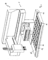
- a work deck 15 on which different samples 16, 17, which must be pipetted, can be arranged.
- the spacings of the pipetting needles can be adapted to the spacings of the samples 16, 17.
- the working deck 15 can be fastened to the column 3 and exchanged. At one end, the working deck 15 has tabs 18, 19, which serve to connect an adjacent robot module 1.
- Fig. 3 are three similar robotic modules 1.1, 1.2, 1.3 lined up, and thus result in a robot assembly 20.
- the special feature of the robot assembly 20 is that the Y-axis arms 5.1, 4.2, 5.2, 4.3 on the X-Achsearm 2.1, 2.2, 2.3 of each adjacent robot module 1.1, 1.2, 1.3 can be moved.
- the working modules 9.1, 9.2, 9.3 are designed here as grippers and movable with respect to the associated Y-axis arms in the Z direction.
- hose lines 35 can be seen, which are connected to the working module 9, in particular its pipetting needles 36.
- the hose lines 35 are guided into a housing 37 of the Y-axis arm 4 and finally reach the dispensing module 11, which is arranged in the column 3.
- the coupling device 6 has a plurality of terminals 40, 41, the terminal 40 being designed as an electrical connection and the terminal 41 as a data connection.
- a working module 9 can be flanged.
- Fig. 5 is designed as a pipetting module working module 9 without covers, but only schematically shown.
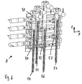
- Pipetting needles 54, 55, 56, 57 are held on the pipetting needle receptacles 50, 51, 52, 53.
- the pipetting needle receptacles 50-53 and thus the pipetting needles 54-57 are limitedly movable in the Y direction. The distances between the pipetting needles 54 - 57 can therefore be adjusted individually.
- the adjustability in the Y direction is effected by spindle drives 58, 59, 60, 61.
- the Pipettiernadelitn 50 - 53 and thus the pipetting needles 54 - 57 are adjustable in the Z direction. The adjustment in the Z direction takes place via rack drives 62, 63, 64, 65.
- the pipetting needles 54-57 are exchangeable. They can be fluidly connected to the dispensing device 11.
Landscapes
- Engineering & Computer Science (AREA)
- Health & Medical Sciences (AREA)
- Chemical & Material Sciences (AREA)
- Robotics (AREA)
- Life Sciences & Earth Sciences (AREA)
- Chemical Kinetics & Catalysis (AREA)
- Mechanical Engineering (AREA)
- Physics & Mathematics (AREA)
- Clinical Laboratory Science (AREA)
- Analytical Chemistry (AREA)
- Biochemistry (AREA)
- General Health & Medical Sciences (AREA)
- General Physics & Mathematics (AREA)
- Immunology (AREA)
- Pathology (AREA)
- Manipulator (AREA)
- Automatic Analysis And Handling Materials Therefor (AREA)
Description
- Die Erfindung betrifft eine Laborroboteranordnung für den Biowissenschaftsbereich (Life-Science-Bereich), umfassend zumindest ein erstes Robotermodul mit einem X-Achsenarm, an dem zumindest ein Y-Achsenarm in X-Richtung bewegbar angeordnet ist.
- Im Life-Science-Bereich müssen Flüssigkeiten, Feststoffe und Objekte automatisiert gehandhabt werden. Beispielsweise müssen aus einer Menge von Proben, Proben mit spezifischen Eigenschaften entnommen werden. Die entnommenen Proben müssen entweder analysiert werden oder anderen Proben zugeführt werden. Auch ist es denkbar, dass Proben verdünnt werden müssen. Weitere Anwendungen sind möglich und denkbar. Da diese Vorgänge häufig standardisiert sind, sollten Sie vorzugsweise automatisiert ablaufen. Zu diesem Zweck sind bereits verschiedenste Roboteranordnungen bekannt. Häufig sind die bekannten Anordnungen nur für wenige Aufgaben geeignet.
WO03/061830 - Erfindungsgemäß wird diese Aufgabe auf ebenso überraschende wie wirkungsvolle Art und Weise mit einer Roboteranordnung gemäβ Anspruch 1 gelöst.
- Hier mit wird die Modularität des Systems erhöht. Zudem ist es möglich, dass die Y-Achsenarme nahezu den gesamten Arbeitsbereich überfahren können. Dadurch sind größere Anordnungen von Proben handhabbar. Die Roboteranordnung kann mit einer Verbindung zu einem Ablagesystem ausgestattet sein.
- Bei einer Ausführungsform, die auch als eigenständige Erfindung betrachtet wird, kann vorgesehen sein, dass an dem Y-Achsenarm eine in Y-Richtung bewegbare Ankoppeleinrichtung zum Ankoppeln eines Arbeitsmoduls vorgesehen ist. Durch diese Maßnahme ist es möglich, die Roboteranordnung für verschiedene Einsatzzwecke zu nutzen. Während im Stand der Technik beispielsweise Roboteranordnungen bekannt sind, bei denen an einem Y-Achsenarm Pipettiernadeln fest installiert sind und der Y-Achsenarm daher ausschließlich zum Pipettieren verwendet werden kann, ist es mit der erfindungsgemäßen Anordnung möglich, an den Y-Achsenarmen unterschiedlichste Arbeitsmodule anzukoppeln, sodass der Y-Achsenarm je nach angekoppeltem Arbeitsmodul unterschiedlich einsetzbar ist. Beispielsweise kann ein Pipettiermodul oder auch ein Greifer-Modul angekoppelt werden. Durch den Wechsel von Pipettiermodulen können auch Pipettiernadeln schneller ausgetauscht werden. Die erfindungsgemäße Roboteranordnung zeichnet sich daher durch eine große Modularität aus.
- Vorzugsweise sind benachbarte Robotermodule miteinander verbindbar. Die Verbindung kann dabei als Rast- und/oder Steckverbindung ausgebildet sein. Benachbarte X-Achsenarme können dadurch zu einem gemeinsamen X-Achsenarm verbunden werden und/oder in Anlage aneinander gehalten werden.
- Um ein störungsfreies Übergehen eines Y-Achsenarms auf den X-Achsenarm eines benachbarten Robotermoduls sicherzustellen, ist es vorteilhaft, wenn die den Y-Achsenarmen zugeordneten Kabelführungen benachbarter Robotermodule in unterschiedlichen Ebenen angeordnet sind. Um ein Übergehen eines Y-Achsenarms zu ermöglichen, kann es notwendig sein, die Kabelführung für diesen Y-Achsenarm zu verlängern beziehungsweise standardmäßig eine längere Kabelführung vorzusehen oder eine bestehende Kabelführung durch eine längere zu ersetzen.
- Die Robotermodule sind besonders einfach einsetzbar und handhabbar, wenn sie als Tischgerät ausgebildet sind. Werden größere Roboteranordnungen benötigt, können mehrere Robotermodule einfach aneinander gereiht werden.
- Bei einer besonders bevorzugten Ausführungsform können an zumindest einem Robotermodul zumindest zwei Y-Achsenarme vorgesehen sein. Beispielsweise kann an einem ersten Y-Achsenarm ein Pipettiermodul und an einem zweiten Y-Achsenarm ein Greifermodul vorgesehen sein. Durch das Pipettiermodul können beispielsweise Proben aus Behältern entnommen werden und durch das Greifermodul können Proben beziehungsweise Behälter ausgetauscht werden. Es ist jedoch auch denkbar, an beiden Y-Achsenarmen Pipettiermodule vorzusehen, um dadurch das Bearbeiten einer Charge zu beschleunigen oder größere Chargen bearbeiten zu können.
- Die Einsatzmöglichkeiten werden erweitert, wenn das Arbeitsmodul in Z-Richtung bewegbar ist. Dazu ist es vorzugsweise als Z-Achsenarm ausgebildet oder umfasst einen Z-Achsenarm. Denkbar ist jedoch auch, dass die Anköppeteinrichtung relativ zum Y-Achsenarm in Z-Richtung bewegbar und antreibbar ist. Wenn das Arbeitsmodul als Z-Achsenarm ausgebildet ist, kann an diesen wiederum ein Arbeitsmodul, wie ein Pipettiermodul oder ein Greifermodul, angekoppelt werden. Alternativ kann an dem anzukoppelnden Arbeitsmodul ein Z-Achsenarm vorgesehen sein, der eine Bewegung des (übrigen) Arbeitsmoduls relativ zum Y-Achsenarm in Z-Richtung erlaubt. Für die Pipettiernadeln eines Pipettiermoduls ergeben sich daher zwei Verstellmöglichkeiten in Z-Richtung, einmal über das Arbeitsmodul relativ zum Y-Achsenarm und einmal relativ zum Arbeitsmodul.
- Bei einer bevorzugten Weiterbildung kann vorgesehen sein, dass beide Y-Achsenarme zumindest eine Ankoppeleinrichtung aufweisen. Dadurch können noch mehr unterschiedliche oder gleichartige Arbeitsmodule angekoppelt und eingesetzt werden. Die Modularität und der Einsatzbereich werden dadurch weiter erhöht bzw. vergrößert.
- Bei einer besonders bevorzugten Ausführungsform kann vorgesehen sein, dass zumindest ein Y-Achsenarm zwei Ankoppeleinrichtungen aufweist. Vorzugsweise sind die Ankoppeleinrichtungen unabhängig voneinander in Y-Richtung bewegbar. Besonders bevorzugt ist es, wenn sie in X-Richtung gesehen an unterschiedlichen Seiten des Y-Achsenarms angeordnet sind und individuell antreibbar sind.
- In bevorzugter Ausgestaltung der Erfindung kann vorgesehen sein, dass die Ankoppeleinrichtung Anschlüsse, insbesondere einen elektrischen Anschluss und/oder Datenanschluss, für das anzukoppelnde Arbeitsmodul aufweist. Es können unterschiedliche Maßnahmen vorgesehen sein, um das Arbeitsmodul an der Ankoppeleinrichtung befestigen zu können. Beispielsweise kann das Arbeitsmodul angeflanscht werden. Es kann jedoch auch eine Rastverbindung oder ein bajonettartiger Verschluss vorgesehen sein.
- Um die Elemente des Arbeitsmoduls betätigen zu können, müssen Anschlüsse zur übrigen Roboteranordnung beziehungsweise zum Robotermodul hergestellt werden. Insbesondere ist es vorteilhaft, wenn das Arbeitsmodul über das Robotermodul mit elektrischer Energie versorgt werden kann. Zur Steuerung des Arbeitsmoduls ist es weiterhin vorteilhaft, wenn ein Datenaustausch des Arbeitsmoduls mit einer Steuereinrichtung des Robotermoduls oder der Roboteranordnung möglich ist. Vorzugsweise werden die entsprechenden Verbindungen beim Ankoppeln des Arbeitsmoduls an die Ankoppeleinrichtung selbsttätig hergestellt. Außer den erwähnten Anschlüssen können noch weitere Anschlüsse, beispielsweise ein Pneumatikanschluss oder ein Hydraulikanschluss vorgesehen sein.
- Vorzugsweise weist das Robotermodul einen Datenbus, beispielsweise einen CAN-Bus oder Interbus, auf. Daher ist es günstig, wenn der Datenanschluss als Bus-Anbindung, insbesondere als Schnittstelle zu einem CAN-Bus oder Interbus, ausgebildet ist.
- Die Relativbewegung des Y-Achsenarms bezüglich des X-Achsenarms und der Ankoppeleinrichtungen bezüglich des Y-Achsenarms erfolgt vorzugsweise über Antriebe. Eine genaue Positionierung wird ermöglicht, wenn zumindest ein Antrieb einen Linearmotor umfasst. Vorzugsweise umfassen alle Achsenantriebe einen Linearmotor. Insbesondere, wenn zwei Ankoppeleinrichtungen an einem Y-Achsenarm vorgesehen sind, können zwei Linearmotoren denselben Stator nutzen. Die Ankoppeleinrichtungen können individuell oder an einem Y-Achsenarm gemeinsam verfahrbar sein.
- Bei einer Ausführungsform kann das Arbeitsmodul als Pipettiermodul ausgebildet sein. Dies hat den Vorteil, dass für unterschiedliche Proben unterschiedliche Pipetten und gegebenenfalls Pipetten mit unterschiedlichen Volumina verwendet werden können. Die Pipetten sind daher im Vergleich zum Stand der Technik einfach austauschbar. Ist das Pipettieren abgeschlossen, kann auch das Pipettiermodul gegen ein anderes Arbeitsmodul ausgetauscht werden.
- Besonders bevorzugt ist es, wenn das Pipettiermodul mehrere Pipettiernadelaufnahmen und/oder Pipettiernadeln aufweist, die relativ zum Pipettiermodul begrenzt, insbesondere individuell, in Y-Richtung bewegbar sind. Dadurch können gleichzeitig Proben aus unterschiedlichen Behältern entnommen werden, die entweder unterschiedlich groß sind oder unterschiedliche Abstände aufweisen. Das Pipettiermodul kann fest installierte Pipettiernadeln aufweisen, mit oder ohne Piercing-Funktionalität. Das Vorsehen von Pipettiernadelaufnahmen hat den Vorteil, dass Einwegpipetten verwendet werden können. Vorzugsweise weist ein Pipettiermodul mehrere, insbesondere 4, 8 oder 12 Pipettiernadelaufnahmen und/oder Pipettiernadeln auf. Bevorzugt sind die Pipettiernadelaufnahmen und/oder Pipettiernadeln individuell in Y-Richtung bewegbar und verstellbar.
- Die Abstände zwischen benachbarten Pipettiernadelaufnahmen und/oder Pipettiernadeln können dabei zum Beispiel im Bereich 4 - 25 mm, vorzugsweise 9 - 20 mm einstellbar sein.
- Die Verstellung der Position der Pipettiernadelaufnahmen und/oder Pipettiernadeln kann einfach realisiert werden, wenn für die Bewegung der Pipettiernadelaufnahmen und/oder Pipettiernadeln in Y-Richtung (Kugel-)Spindelantriebe, Piezo- oder Zahnstangenantriebe vorgesehen sind.
- Da die Behälter unter Umständen in unterschiedlichen horizontalen Lagen angeordnet sind und/oder unterschiedliche Füllstände aufweisen, ist es vorteilhaft, wenn die Pipettiernadelaufnahmen und/oder Pipettiernadeln, insbesondere individuell, in Z-Richtung relativ zum Arbeitsmodul bewegbar sind.
- Für die Bewegung der Pipettiernadelaufnahmen und/oder Pipettiernadeln in Z-Richtung sind dabei in bevorzugter Ausgestaltung der Erfindung Zahnstangenantriebe, Piezoantriebe oder (Kugel-)Spindelantriebe vorgesehen.
- Bei einer besonders bevorzugten Ausführungsform der Erfindung kann ein austauschbares Dispensmodul vorgesehen sein, das mit den Pipettiernadeln, insbesondere fluidisch, verbindbar ist. Das Pipettieren kann auf unterschiedliche Art und Weise erfolgen. Beispielsweise können Kolbenhubpipetten, eine Mikropumpe oder ein Pipettieren über eine Flüssigkeitssäule vorgesehen sein. Bei den meisten Pipettierverfahren ist eine Dispenseinrichtung notwendig, die fluidisch mit den Pipetten verbunden ist. Um je nach eingesetztem Pipettiermodul unterschiedliche Pipettierverfahren anwenden zu können, ist es vorteilhaft, wenn die Dispenseinrichtung entsprechend ausgetauscht werden kann und daher ebenfalls als Modul ausgebildet ist.
- Die erfindungsgemäße Roboteranordnung, insbesondere ein Robotermodul der Roboteranordnung, kann mit Robotern anderer Hersteller kombiniert werden. Besonders vorteilhaft ist jedoch eine Verwendung als Tischgerät, wobei mit einem Pipettiermodul gleichzeitig mehrere Proben aus einer Anordnung von Behältern entnommen werden. Zu diesem Zweck ist es besonders vorteilhaft, wenn unterhalb des zumindest einen Y-Achsenarms ein Arbeitsdeck vorgesehen ist, das die Proben enthalten kann oder auf dem die Behälter abgestellt sein können. Vorzugsweise ist das Arbeitsdeck austauschbar und an einer Säule des Robotermoduls befestigbar.
- Die Roboteranordnung kann beispielsweise als Zelle ausgebildet sein, die einen Knickarmroboter umfasst. Über den Knickarmroboter können Objekte, die beispielsweise analysiert werden müssen, bewegt werden. Mit einem Knickarmroboter können weitere Freiheitsgrade der Bewegung erreicht werden. Außerdem können die Y-Achsenarme des Robotermoduls überwiegend für Analysetätigkeiten verwendet werden.
- Besonders bevorzugt ist es, wenn eine Füllstandserkennung zur Detektion des Füllstands eines Behälters vorgesehen ist. Dadurch kann sichergestellt werden, dass eine Pipettiernadel auch in die aufzunehmende Flüssigkeit eintaucht.
- Weitere Merkmale und Vorteile der Erfindung ergeben sich aus der nachfolgenden detaillierten Beschreibung von Ausführungsbeispielen der Erfindung anhand der Figuren der Zeichnung, die erfindungswesentliche Einzelheiten zeigt, sowie aus den Ansprüchen.
- In der schematischen Zeichnung sind Ausführungsbeispiele der Erfindung dargestellt, welche in der nachfolgenden Beschreibung näher erläutert werden.
-
- Fig. 1
- eine perspektivische Ansicht eines Robotermoduls einer Roboteranordnung;
- Fig. 2
- eine perspektivische Ansicht eines Robotermoduls mit Arbeitsdeck;
- Fig. 3
- eine Darstellung einer Roboteranordnung mit mehreren Robotermodulen;
- Fig. 4a
- eine perspektivische Vorderansicht eines Y-Achsenarms;
- Fig. 4b
- eine perspektivische Rückansicht des Y-Achsenarms;
- Fig. 5
- eine Darstellung eines Pipettiermoduls;
- Fig. 6
- eine weitere Darstellung eines Pipettiermoduls.
- In der
Fig. 1 ist ein Robotermodul 1 einer Roboteranordnung 10 gezeigt. Das Robotermodul 1 weist einen X-Achsenarm 2 auf, der an einer Säule 3 des Robotermoduls 1 befestigt ist. An dem X-Achsenarm 2 ist ein Y-Achsenarm 4 angeordnet, wobei der Y-Achsenarm 4 relativ zum X-Achsenarm 2 in Richtung der X-Achse bewegbar ist. Der Y-Achsenarm 4 weist zwei Ankoppeleinrichtungen 6 (sieheFig. 4b ) auf, die zur Kopplung mit einem Arbeitsmodul 9 geeignet sind. Im Ausführungsbeispiel ist das Arbeitsmodul 9 als Pipettiermodul ausgebildet. Die Ankoppeleinrichtungen 6 und somit das Arbeitsmodul 9 sind in Richtung der Y-Achsen relativ zum Y-Achsenarm 4 bewegbar. Zum Bewegen der Ankoppeleinrichtungen 6 und des Y-Achsenarms 4 sind Linearmotoren vorgesehen, die in den Achsenarmen angeordnet sind. An der Säule 3 ist ein Dispensmodul 11 angeordnet, welches mit Pipettiernadeln des Arbeitsmoduls 9 über Schlauchleitungen verbindbar ist. - Im Unterschied zur Darstellung der
Fig. 1 weist die Roboteranordnung 10 gemäß derFig. 2 noch zusätzlich ein Arbeitsdeck 15 auf, auf dem unterschiedliche Proben 16, 17, die pipettiert werden müssen, angeordnet sein können. Wie später noch näher erläutert werden wird, können die Abstände der Pipettiernadeln auf die Abstände der Proben 16,17 angepasst werden. Das Arbeitsdeck 15 ist an der Säule 3 befestigbar und austauschbar. Einenends weist das Arbeitsdeck 15 Laschen 18, 19 auf, die zum Anschluss eines benachbarten Robotermoduls 1 dienen. - In der
Fig. 3 sind drei gleichartige Robotermodule 1.1, 1.2, 1.3 aneinander gereiht, und ergeben somit eine Roboteranordnung 20. Die Besonderheit der Roboteranordnung 20 liegt darin, dass die Y-Achsenarme 5.1, 4.2, 5.2, 4.3 auf den X-Achsenarm 2.1, 2.2, 2.3 des jeweils benachbarten Robotermoduls 1.1, 1.2, 1.3 verfahren werden können. Die Arbeitsmodule 9.1, 9.2, 9.3 sind hier als Greifer ausgebildet und bezüglich der zugeordneten Y-Achsenarme in Z-Richtung bewegbar. - In der Detaildarstellung des Y-Achsenarms 4 der
Fig. 4a sind Schlauchleitungen 35 zu erkennen, die an das Arbeitsmodul 9, insbesondere dessen Pipettiernadeln 36 angeschlossen sind. Anderenendes sind die Schlauchleitungen 35 in ein Gehäuse 37 des Y-Achsenarms 4 geführt und gelangen letztendlich zu dem Dispensmodul 11, das in der Säule 3 angeordnet ist. - Gemäß der Rückansicht der
Fig. 4b weist die Ankoppeleinrichtung 6 mehrere Anschlüsse 40, 41 auf, wobei der Anschluss 40 als elektrischer Anschluss und der Anschluss 41 als Datenanschluss ausgebildet sind. Über die Gewindebohrungen 42, 43 kann ein Arbeitsmodul 9 angeflanscht werden. - In der
Fig. 5 ist ein als Pipettiermodul ausgebildetes Arbeitsmodul 9 ohne Abdeckungen, jedoch nur schematisch, dargestellt. An den Pipettiernadelaufnahmen 50, 51, 52, 53 sind Pipettiernadeln 54, 55, 56, 57 gehalten. Die Pipettiernadelaufnahmen 50 - 53 und somit die Pipettiernadeln 54 - 57 sind begrenzt in Y-Richtung bewegbar. Die Abstände zwischen den Pipettiernadeln 54 - 57 lassen sich daher individuell einstellen. Die Verstellbarkeit in Y-Richtung wird durch Spindelantriebe 58, 59, 60, 61 bewirkt. Außerdem sind die Pipettiernadelaufnahmen 50 - 53 und damit die Pipettiernadeln 54 - 57 in Z-Richtung verstellbar. Die Verstellung in Z-Richtung erfolgt über Zahnstangenantriebe 62, 63, 64, 65. Die Pipettiernadeln 54 - 57 sind austauschbar. Sie können fluidisch mit der Dispenseinrichtung 11 verbunden werden. - Aus der
Fig. 6 wird deutlich, dass die Pipettiernadelaufnahmen 50 - 53 und damit die Pipettiernadeln 54 - 57 sowohl in Y-Richtung als auch in Z-Richtung individuell und unabhängig voneinander verstellbar sind. Insbesondere lassen sich unterschiedliche Abstände zwischen den Pipettiernadelaufnahmen 50 - 53 in Y-Richtung realisieren.
Claims (15)
- Laborroboteranordnung (10, 20) für den Biowissenschaftsbereich, umfassend zumindest ein erstes Robotermodul (1, 1.1, 1.2, 1.3) mit einem X-Achsenarm (2, 2.1, 2.2, 2.3), an dem zumindest ein Y-Achsenarm (4, 4.2, 4.3, 5.1, 5.2) in X-Richtung bewegbar angeordnet ist, dadurch gekennzeichnet, dass die Roboteranordnung (10, 20) mehrere Robotermodule (1, 1.1, 1.2,1.3) aufweist, die in X-Richtung nebeneinander angeordnet sind, wobei jedes Robotermodul (1, 1.1, 1.2, 1.3) einen X-Achsenarm (2, 2.1, 2.2, 2.3) und einen Y-Achsenarm (4, 4.2, 4.3, 5.1, 5.2) aufweist und wobei zumindest ein Y-Achsenarm (4, 4.2, 4.3, 5.1, 5.2) eines ersten Robotermoduls (1, 1.1, 1.2, 1.3) zumindest abschnittsweise entlang des X-Achsenarms (2, 2.1, 2.2 , 2.3) eines benachbarten Robotermoduls (1, 1.1, 1.2, 1.3) bewegbar ist.
- Laborroboteranordnung nach Anspruch 1, dadurch gekennzeichnet, dass an dem Y-Achsenarm (4, 4.2, 4.3, 5.1, 5.2) eine in Y-Richtung bewegbare Ankoppeleinrichtung (6) zum Ankoppeln eines Arbeitsmoduls (9, 9.1, 9.2, 9.3) vorgesehen ist.
- Laborroboteranordnung nach Anspruch 1 oder 2, dadurch gekennzeichnet, dass benachbarte Robotermodule (1, 1.1, 1.2, 1.3) miteinander verbindbar sind.
- Laborroboteranordnung nach Anspruch 1, 2 oder 3, dadurch gekennzeichnet, dass die den Y-Achsen zugeordneten Kabelführungen benachbarter Robotermodule (1, 1.1, 1.2, 1.3) in unterschiedlichen Ebenen angeordnet sind.
- Laborroboteranordnung nach einem der vorhergehenden Ansprüche, dadurch gekennzeichnet, dass das oder die Robotermodule (1, 1.1, 1.2, 1.3) als Tischgerät ausgebildet sind.
- Laborroboteranordnung nach einem der vorhergehenden Ansprüche, dadurch gekennzeichnet, dass an zumindest einem Robotermodul (1, 1.1,1.2, 1.3) zumindest zwei Y-Achsenarme (4, 4.2, 4.3, 5.1, 5.2) vorgesehen sind.
- Laborroboteranordnung nach Anspruch 6, dadurch gekennzeichnet, dass beide Y-Achsenarme (4, 4.2, 4.3, 5.1, 5.2) zumindest eine Ankoppeleinrichtung (6) aufweisen.
- Laborroboteranordnung nach einem der vorhergehenden Ansprüche, dadurch gekennzeichnet, dass zumindest ein Y-Achsenarm (4, 4.2, 4.3, 5.1, 5.2) zwei Ankoppeleinrichtungen (6) aufweist.
- Laborroboteranordnung nach Anspruch 8, dadurch gekennzeichnet, dass die Ankoppeleinrichtungen (6) am Y-Achsenarm unabhängig voneinander in Y-Richtung bewegbar sind.
- Laborroboteranordnung nach einem der vorhergehenden Ansprüche, dadurch gekennzeichnet, dass die Ankoppeleinrichtung (6) Anschlüsse (40, 41), insbesondere einen elektrischen Anschluss und/oder Datenanschluss für das anzukoppelnde Arbeitsmodul (9, 9.1, 9.2, 9.3) aufweist.
- Laborroboteranordnung nach einem der vorhergehenden Ansprüche, dadurch gekennzeichnet, dass der Datenanschluss als Bus-Anbindung, insbesondere als Schnittstelle zu einem CAN-Bus oder Interbus, ausgebildet ist.
- Laborroboteranordnung nach einem der vorhergehenden Ansprüche, dadurch gekennzeichnet, dass in oder an den Achsenarmen (2, 2.1 , 2.2 , 2.3, 4, 4.2, 4.3, 5.1, 5.2) Antriebe vorgesehen sind, wobei zumindest ein Antrieb einen Linearmotor umfasst.
- Laborroboteranordnung nach einem der vorhergehenden Ansprüche, dadurch gekennzeichnet, dass das Arbeitsmodul (9, 9.1, 9.2, 9.3) als Pipettiermodul ausgebildet ist.
- Laborroboteranordnung nach einem der vorhergehenden Ansprüche, dadurch gekennzeichnet, dass das Pipettiermodul mehrere Pipettiernadelaufnahmen (50 - 53)und/oder Pipettiernadeln (54 - 57) aufweist, die relativ zum Pipettiermodul begrenzt, insbesondere individuell, in Y-Richtung bewegbar sind.
- Laborroboteranordnung nach einem der vorhergehenden Ansprüche, dadurch gekennzeichnet, dass die Abstände zwischen benachbarten Pipettiernadelaufnahmen (50 - 53) und/oder Pipettiernadeln (54 - 57) zum Beispiel im Bereich 4 - 25 mm, vorzugsweise 9 - 20 mm einstellbar sind.
Priority Applications (1)
| Application Number | Priority Date | Filing Date | Title |
|---|---|---|---|
| EP09011368A EP2144067B1 (de) | 2005-10-17 | 2006-09-30 | Laborroboteranordnung |
Applications Claiming Priority (2)
| Application Number | Priority Date | Filing Date | Title |
|---|---|---|---|
| DE102005049920A DE102005049920A1 (de) | 2005-10-17 | 2005-10-17 | Roboteranordnung |
| PCT/EP2006/009507 WO2007045341A2 (de) | 2005-10-17 | 2006-09-30 | Laborroboteranordnung |
Related Child Applications (1)
| Application Number | Title | Priority Date | Filing Date |
|---|---|---|---|
| EP09011368A Division EP2144067B1 (de) | 2005-10-17 | 2006-09-30 | Laborroboteranordnung |
Publications (2)
| Publication Number | Publication Date |
|---|---|
| EP1941283A2 EP1941283A2 (de) | 2008-07-09 |
| EP1941283B1 true EP1941283B1 (de) | 2009-12-23 |
Family
ID=37684303
Family Applications (2)
| Application Number | Title | Priority Date | Filing Date |
|---|---|---|---|
| EP09011368A Not-in-force EP2144067B1 (de) | 2005-10-17 | 2006-09-30 | Laborroboteranordnung |
| EP06792332A Not-in-force EP1941283B1 (de) | 2005-10-17 | 2006-09-30 | Labor-roboter-anordnung |
Family Applications Before (1)
| Application Number | Title | Priority Date | Filing Date |
|---|---|---|---|
| EP09011368A Not-in-force EP2144067B1 (de) | 2005-10-17 | 2006-09-30 | Laborroboteranordnung |
Country Status (5)
| Country | Link |
|---|---|
| US (1) | US20080240898A1 (de) |
| EP (2) | EP2144067B1 (de) |
| AT (2) | ATE555389T1 (de) |
| DE (2) | DE102005049920A1 (de) |
| WO (1) | WO2007045341A2 (de) |
Cited By (2)
| Publication number | Priority date | Publication date | Assignee | Title |
|---|---|---|---|---|
| US10168347B2 (en) | 2016-05-23 | 2019-01-01 | Becton, Dickinson And Company | Liquid dispenser with manifold mount for modular independently-actuated pipette channels |
| US10234474B2 (en) | 2007-07-13 | 2019-03-19 | Handylab, Inc. | Automated pipetting apparatus having a combined liquid pump and pipette head system |
Families Citing this family (47)
| Publication number | Priority date | Publication date | Assignee | Title |
|---|---|---|---|---|
| US7829025B2 (en) | 2001-03-28 | 2010-11-09 | Venture Lending & Leasing Iv, Inc. | Systems and methods for thermal actuation of microfluidic devices |
| US8895311B1 (en) | 2001-03-28 | 2014-11-25 | Handylab, Inc. | Methods and systems for control of general purpose microfluidic devices |
| EP1654066B1 (de) | 2003-07-31 | 2014-11-12 | Handylab, Inc. | Verarbeitung von teilchenhaltigen proben |
| US8852862B2 (en) | 2004-05-03 | 2014-10-07 | Handylab, Inc. | Method for processing polynucleotide-containing samples |
| US7998708B2 (en) | 2006-03-24 | 2011-08-16 | Handylab, Inc. | Microfluidic system for amplifying and detecting polynucleotides in parallel |
| DK2001990T3 (en) | 2006-03-24 | 2016-10-03 | Handylab Inc | Integrated microfluidic sample processing system and method for its use |
| US10900066B2 (en) | 2006-03-24 | 2021-01-26 | Handylab, Inc. | Microfluidic system for amplifying and detecting polynucleotides in parallel |
| US11806718B2 (en) | 2006-03-24 | 2023-11-07 | Handylab, Inc. | Fluorescence detector for microfluidic diagnostic system |
| WO2008061165A2 (en) | 2006-11-14 | 2008-05-22 | Handylab, Inc. | Microfluidic cartridge and method of making same |
| WO2008060604A2 (en) | 2006-11-14 | 2008-05-22 | Handylab, Inc. | Microfluidic system for amplifying and detecting polynucleotides in parallel |
| US8105783B2 (en) | 2007-07-13 | 2012-01-31 | Handylab, Inc. | Microfluidic cartridge |
| US8182763B2 (en) | 2007-07-13 | 2012-05-22 | Handylab, Inc. | Rack for sample tubes and reagent holders |
| US9618139B2 (en) | 2007-07-13 | 2017-04-11 | Handylab, Inc. | Integrated heater and magnetic separator |
| US9186677B2 (en) | 2007-07-13 | 2015-11-17 | Handylab, Inc. | Integrated apparatus for performing nucleic acid extraction and diagnostic testing on multiple biological samples |
| US8324372B2 (en) | 2007-07-13 | 2012-12-04 | Handylab, Inc. | Polynucleotide capture materials, and methods of using same |
| US20090181359A1 (en) * | 2007-10-25 | 2009-07-16 | Lou Sheng C | Method of performing ultra-sensitive immunoassays |
| US8222048B2 (en) | 2007-11-05 | 2012-07-17 | Abbott Laboratories | Automated analyzer for clinical laboratory |
| EP2191942A1 (de) * | 2008-11-26 | 2010-06-02 | F. Hoffmann-Roche AG | Multifunktionswerkzeug |
| US8900878B2 (en) | 2008-11-28 | 2014-12-02 | Roche Molecular Systems Inc. | Pipetting device, modular pipetting unit, pipetting system and method for pipetting of fluid samples |
| KR102052096B1 (ko) * | 2009-05-15 | 2019-12-04 | 바이오메리욱스, 인코포레이티드. | 자동 미생물 탐지 장치 |
| JP2012526996A (ja) * | 2009-05-15 | 2012-11-01 | ビオメリュー・インコーポレイテッド | 試料内の微生物因子の迅速な同定および/または特徴付けのためのシステムおよび方法 |
| EP2261676B8 (de) * | 2009-06-12 | 2015-03-18 | CTC Analytics AG | Werkzeug zur Handhabung einer Probe |
| DE102009043570A1 (de) | 2009-09-30 | 2011-03-31 | Manz Automation Tübingen GmbH | Modul für einen Laborroboter und Laborroboter |
| EP2363713B1 (de) * | 2010-03-04 | 2015-06-03 | F.Hoffmann-La Roche Ag | Hardware-Architektur für Analysiergeräte |
| DE102010064049A1 (de) * | 2010-12-23 | 2012-06-28 | Hamilton Bonaduz Ag | Pipettiervorrichtung mit Linearmotor |
| EP2697657B8 (de) | 2011-04-15 | 2017-08-16 | Becton, Dickinson and Company | Mikrofluidischer abtastender echtzeit-thermocycler und verfahren zur optischen detektion mittels synchronisierter thermozyklierung und abtastung |
| USD692162S1 (en) | 2011-09-30 | 2013-10-22 | Becton, Dickinson And Company | Single piece reagent holder |
| DK3273253T3 (da) | 2011-09-30 | 2020-10-12 | Becton Dickinson Co | Forenet reagensstrimmel |
| EP2773892B1 (de) | 2011-11-04 | 2020-10-07 | Handylab, Inc. | Vorrichtung zur vorbereitung von polynukleotidproben |
| DK2810080T3 (da) | 2012-02-03 | 2024-06-17 | Becton Dickinson Co | Eksterne filer til fordeling af molekylære diagnostiske tests og bestemmelse af kompatabilitet imellem tests |
| DE102013200193A1 (de) | 2013-01-09 | 2014-07-10 | Hamilton Bonaduz Ag | Probenverarbeitungssystem mit Dosiervorrichtung und Thermocycler |
| DE202013003390U1 (de) | 2013-04-11 | 2014-07-14 | Brand Gmbh + Co Kg | Pipettiervorrichtung mit einer Mikrodosiereinheit |
| ES3027682T3 (en) * | 2014-06-11 | 2025-06-16 | Hoffmann La Roche | In-vitro diagnostic analysis method and system |
| WO2016018910A1 (en) * | 2014-07-28 | 2016-02-04 | Douglas Scientific, LLC | Instrument for analyzing biological samples and reagents |
| DE202014006241U1 (de) * | 2014-08-07 | 2015-11-12 | Brand Gmbh + Co Kg | Pipettiervorrichtung mit einer Mikrodosiereinheit |
| WO2017064089A1 (en) | 2015-10-13 | 2017-04-20 | F. Hoffmann-La Roche Ag | Pipetting device for an apparatus for processing a sample or reagent, apparatus for processing a sample or reagent and method for pipetting a sample or reagent |
| DE202016004140U1 (de) | 2016-07-05 | 2017-10-08 | Brand Gmbh + Co Kg | Pipettiervorrichtung zum Aspirieren und Dispensieren von Flüssigkeiten |
| WO2019010515A1 (de) * | 2017-07-14 | 2019-01-17 | Meon Medical Solutions Gmbh & Co Kg | Automatische pipettiervorrichtung für den proben- und/oder reagenzientransfer und verfahren zum transferieren von flüssigen proben und/oder reagenzien |
| CN109895067A (zh) * | 2017-12-07 | 2019-06-18 | 天津西青区瑞博生物科技有限公司 | 一种升降式色选机械手 |
| EP3625574B1 (de) | 2017-12-21 | 2023-08-23 | Leica Biosystems Melbourne Pty Ltd | Flüssigkeitstransportsystem |
| WO2019204841A1 (de) | 2018-04-23 | 2019-10-31 | Meon Medical Solutions Gmbh & Co Kg | Automatischer analysator und optisches messverfahren zur gewinnung von messsignalen von flüssigen medien |
| WO2020142798A1 (de) | 2019-01-11 | 2020-07-16 | Meon Medical Solutions Gmbh & Co Kg | Pipettiervorrichtung und verfahren zum transferieren von flüssigkeiten |
| CN110014421B (zh) * | 2019-04-28 | 2024-09-13 | 上海仁度生物科技股份有限公司 | 一种用于转移液体和搬运容器的机械手装置 |
| CN110551610B (zh) * | 2019-09-29 | 2023-11-21 | 深圳赛动生物自动化有限公司 | 泵液装置及其工作方法 |
| CN110538592B (zh) * | 2019-09-29 | 2024-03-29 | 深圳赛动生物自动化有限公司 | 一种自动配液装置及其工作方法 |
| DE102020200295A1 (de) * | 2020-01-13 | 2021-07-15 | Festo Se & Co. Kg | Positioniersystem zum Positionieren von Endeffektoren |
| BE1030467B1 (fr) * | 2022-04-20 | 2023-11-20 | Quantoom Biosciences S A | Bras robotique pour la manipulation de milieux liquides, système comprenant ledit bras robotique et méthode pour la manipulation de milieux liquides |
Family Cites Families (14)
| Publication number | Priority date | Publication date | Assignee | Title |
|---|---|---|---|---|
| DE3805808A1 (de) * | 1988-02-24 | 1989-09-07 | Europ Lab Molekularbiolog | Automatische arbeitsstation fuer mikrobiologische arbeiten |
| GB2310006B (en) * | 1995-12-01 | 2000-01-12 | Genetix Ltd | Pneumatic actuator |
| DE29720432U1 (de) * | 1997-11-19 | 1999-03-25 | Heimberg, Wolfgang, Dr., 85560 Ebersberg | Roboter |
| DE10017802A1 (de) * | 2000-04-10 | 2001-10-11 | Bilatec Ges Zur Entwicklung Bi | Labor-Roboter mit Vielzweckgreifer |
| JP3723021B2 (ja) * | 1999-09-30 | 2005-12-07 | 富士写真フイルム株式会社 | マイクロアレイチップ製造装置 |
| JP2001211873A (ja) * | 2000-02-03 | 2001-08-07 | Mitsubishi Chemicals Corp | スポッティングヘッド |
| US6912443B2 (en) * | 2000-03-10 | 2005-06-28 | David W. Duemler | Modular automated assembly system |
| EP1363736B1 (de) * | 2000-12-18 | 2011-03-02 | Protedyne Corporation | Extrudieren von gel für gel elektrophorese |
| EP1451674A4 (de) * | 2001-10-26 | 2008-08-20 | Sequenom Inc | Verfahren und vorrichtung zur parallelen ausgabe definierter volumen von festpartikeln |
| WO2003061830A1 (en) * | 2002-01-25 | 2003-07-31 | Thermo Crs Ltd. | Modular robotic system for sample processing |
| US20040141885A1 (en) * | 2002-02-12 | 2004-07-22 | Molecular Devices Corp. | Pipettor systems and components |
| US7105129B2 (en) * | 2002-05-15 | 2006-09-12 | Genetix Limited | Liquid handling robot for well plates |
| US20040253148A1 (en) * | 2003-06-16 | 2004-12-16 | Leaton John R. | Multiple probe expansion (MPX™) accessory device for manual, semi-automated and automated liquid handling equipment federally sponsored research |
| EP1506814A1 (de) * | 2003-08-13 | 2005-02-16 | The Automation Partnership (Cambridge) Limited | Pipettierkopf |
-
2005
- 2005-10-17 DE DE102005049920A patent/DE102005049920A1/de not_active Ceased
-
2006
- 2006-09-30 DE DE502006005750T patent/DE502006005750D1/de active Active
- 2006-09-30 US US12/090,329 patent/US20080240898A1/en not_active Abandoned
- 2006-09-30 AT AT09011368T patent/ATE555389T1/de active
- 2006-09-30 EP EP09011368A patent/EP2144067B1/de not_active Not-in-force
- 2006-09-30 WO PCT/EP2006/009507 patent/WO2007045341A2/de not_active Ceased
- 2006-09-30 EP EP06792332A patent/EP1941283B1/de not_active Not-in-force
- 2006-09-30 AT AT06792332T patent/ATE453120T1/de active
Cited By (2)
| Publication number | Priority date | Publication date | Assignee | Title |
|---|---|---|---|---|
| US10234474B2 (en) | 2007-07-13 | 2019-03-19 | Handylab, Inc. | Automated pipetting apparatus having a combined liquid pump and pipette head system |
| US10168347B2 (en) | 2016-05-23 | 2019-01-01 | Becton, Dickinson And Company | Liquid dispenser with manifold mount for modular independently-actuated pipette channels |
Also Published As
| Publication number | Publication date |
|---|---|
| DE102005049920A1 (de) | 2007-04-19 |
| EP2144067B1 (de) | 2012-04-25 |
| WO2007045341A3 (de) | 2007-11-15 |
| ATE555389T1 (de) | 2012-05-15 |
| ATE453120T1 (de) | 2010-01-15 |
| US20080240898A1 (en) | 2008-10-02 |
| EP1941283A2 (de) | 2008-07-09 |
| EP2144067A1 (de) | 2010-01-13 |
| WO2007045341A2 (de) | 2007-04-26 |
| DE502006005750D1 (de) | 2010-02-04 |
Similar Documents
| Publication | Publication Date | Title |
|---|---|---|
| EP2144067B1 (de) | Laborroboteranordnung | |
| EP2317613B1 (de) | Vorrichtung und Verfahren zum Handhaben der Kabelenden von Kabeln | |
| EP2261676B1 (de) | Werkzeug zur Handhabung einer Probe | |
| DE102007042187B3 (de) | Werkzeugwechselsystem für einen Industrieroboter | |
| EP3119565B1 (de) | Montagevorrichtung zum auswechseln einer greiferspitze eines greiferfingers für ein robotersystem | |
| DE102016111912A1 (de) | Dosierkopf, Dosiervorrichtung umfassend einen Dosierkopf und Verfahren zum Dosieren mittels eines Dosierkopfes | |
| EP3370892B1 (de) | Greifersystem für eine biegepresse | |
| DE102008007233B4 (de) | Schleifmaschine | |
| EP1927429A1 (de) | Werkzeugmaschine mit Werkzeugmagazin | |
| WO2016174133A1 (de) | Bearbeitungsanlage für flugzeugstrukturbauteile | |
| EP2881219A1 (de) | Werkzeugwechselvorrichtung zur Verwendung in einem Bearbeitungszentrum und Bearbeitungszentrum zur maschinellen Bearbeitung eines Werkstücks | |
| DE102007038791B4 (de) | Werkzeugwechselsystem für einen Industrieroboter | |
| EP3197636B1 (de) | Bearbeitungsvorrichtung | |
| EP3242131B1 (de) | Einspannvorrichtung für eine probenvorbereitung | |
| DE10211055B4 (de) | Bewegungs- und/oder Positioniervorrichtung | |
| DE102019130076B4 (de) | Arbeitswerkzeugvorrichtung geeignet für eine Federherstellungsmaschine, Federherstellungsmaschine und Federherstellungsverfahren zum Formen einer Feder | |
| DE202005016326U1 (de) | Roboteranordnung | |
| DE102013220148B3 (de) | Ausgleichseinheit und Ausgleichssystem | |
| DE102017213969B4 (de) | Greifmodul sowie Greifwerkzeug | |
| DE102020127653A1 (de) | Verfahren zum Betrieb einer Anordnung mit einer Werkzeugmaschine und einem Werkzeugwechsler sowie eine entsprechende Anordnung | |
| DE19911382B4 (de) | Werkzeugführungssystem | |
| DE102015121254A1 (de) | Werkzeugwechseleinrichtung | |
| DE102016201690B4 (de) | Adaptionselement, Anbausystem, Handhabungssystem, Kraftfahrzeug und Verfahren zur Montage eines Anbauteils an eine Tragstruktur | |
| DE60204594T2 (de) | Werkzeugwechselvorrichtung | |
| AT518112B1 (de) | Fertigungsanlage mit einer Werkzeug-Manipulationseinheit |
Legal Events
| Date | Code | Title | Description |
|---|---|---|---|
| PUAI | Public reference made under article 153(3) epc to a published international application that has entered the european phase |
Free format text: ORIGINAL CODE: 0009012 |
|
| 17P | Request for examination filed |
Effective date: 20080326 |
|
| AK | Designated contracting states |
Kind code of ref document: A2 Designated state(s): AT BE BG CH CY CZ DE DK EE ES FI FR GB GR HU IE IS IT LI LT LU LV MC NL PL PT RO SE SI SK TR |
|
| RIN1 | Information on inventor provided before grant (corrected) |
Inventor name: OBERDORFER, BEREND Inventor name: MANZ, DIETER |
|
| GRAP | Despatch of communication of intention to grant a patent |
Free format text: ORIGINAL CODE: EPIDOSNIGR1 |
|
| GRAS | Grant fee paid |
Free format text: ORIGINAL CODE: EPIDOSNIGR3 |
|
| GRAA | (expected) grant |
Free format text: ORIGINAL CODE: 0009210 |
|
| AK | Designated contracting states |
Kind code of ref document: B1 Designated state(s): AT BE BG CH CY CZ DE DK EE ES FI FR GB GR HU IE IS IT LI LT LU LV MC NL PL PT RO SE SI SK TR |
|
| REG | Reference to a national code |
Ref country code: GB Ref legal event code: FG4D Free format text: NOT ENGLISH |
|
| REG | Reference to a national code |
Ref country code: CH Ref legal event code: EP |
|
| REG | Reference to a national code |
Ref country code: CH Ref legal event code: NV Representative=s name: ROTTMANN, ZIMMERMANN + PARTNER AG |
|
| REG | Reference to a national code |
Ref country code: IE Ref legal event code: FG4D |
|
| REF | Corresponds to: |
Ref document number: 502006005750 Country of ref document: DE Date of ref document: 20100204 Kind code of ref document: P |
|
| REG | Reference to a national code |
Ref country code: NL Ref legal event code: VDEP Effective date: 20091223 |
|
| PG25 | Lapsed in a contracting state [announced via postgrant information from national office to epo] |
Ref country code: SE Free format text: LAPSE BECAUSE OF FAILURE TO SUBMIT A TRANSLATION OF THE DESCRIPTION OR TO PAY THE FEE WITHIN THE PRESCRIBED TIME-LIMIT Effective date: 20091223 Ref country code: FI Free format text: LAPSE BECAUSE OF FAILURE TO SUBMIT A TRANSLATION OF THE DESCRIPTION OR TO PAY THE FEE WITHIN THE PRESCRIBED TIME-LIMIT Effective date: 20091223 Ref country code: LT Free format text: LAPSE BECAUSE OF FAILURE TO SUBMIT A TRANSLATION OF THE DESCRIPTION OR TO PAY THE FEE WITHIN THE PRESCRIBED TIME-LIMIT Effective date: 20091223 |
|
| LTIE | Lt: invalidation of european patent or patent extension |
Effective date: 20091223 |
|
| PG25 | Lapsed in a contracting state [announced via postgrant information from national office to epo] |
Ref country code: PL Free format text: LAPSE BECAUSE OF FAILURE TO SUBMIT A TRANSLATION OF THE DESCRIPTION OR TO PAY THE FEE WITHIN THE PRESCRIBED TIME-LIMIT Effective date: 20091223 Ref country code: LV Free format text: LAPSE BECAUSE OF FAILURE TO SUBMIT A TRANSLATION OF THE DESCRIPTION OR TO PAY THE FEE WITHIN THE PRESCRIBED TIME-LIMIT Effective date: 20091223 Ref country code: SI Free format text: LAPSE BECAUSE OF FAILURE TO SUBMIT A TRANSLATION OF THE DESCRIPTION OR TO PAY THE FEE WITHIN THE PRESCRIBED TIME-LIMIT Effective date: 20091223 |
|
| REG | Reference to a national code |
Ref country code: IE Ref legal event code: FD4D |
|
| PG25 | Lapsed in a contracting state [announced via postgrant information from national office to epo] |
Ref country code: NL Free format text: LAPSE BECAUSE OF FAILURE TO SUBMIT A TRANSLATION OF THE DESCRIPTION OR TO PAY THE FEE WITHIN THE PRESCRIBED TIME-LIMIT Effective date: 20091223 Ref country code: IS Free format text: LAPSE BECAUSE OF FAILURE TO SUBMIT A TRANSLATION OF THE DESCRIPTION OR TO PAY THE FEE WITHIN THE PRESCRIBED TIME-LIMIT Effective date: 20100423 Ref country code: EE Free format text: LAPSE BECAUSE OF FAILURE TO SUBMIT A TRANSLATION OF THE DESCRIPTION OR TO PAY THE FEE WITHIN THE PRESCRIBED TIME-LIMIT Effective date: 20091223 Ref country code: BG Free format text: LAPSE BECAUSE OF FAILURE TO SUBMIT A TRANSLATION OF THE DESCRIPTION OR TO PAY THE FEE WITHIN THE PRESCRIBED TIME-LIMIT Effective date: 20100323 Ref country code: RO Free format text: LAPSE BECAUSE OF FAILURE TO SUBMIT A TRANSLATION OF THE DESCRIPTION OR TO PAY THE FEE WITHIN THE PRESCRIBED TIME-LIMIT Effective date: 20091223 Ref country code: PT Free format text: LAPSE BECAUSE OF FAILURE TO SUBMIT A TRANSLATION OF THE DESCRIPTION OR TO PAY THE FEE WITHIN THE PRESCRIBED TIME-LIMIT Effective date: 20100423 Ref country code: ES Free format text: LAPSE BECAUSE OF FAILURE TO SUBMIT A TRANSLATION OF THE DESCRIPTION OR TO PAY THE FEE WITHIN THE PRESCRIBED TIME-LIMIT Effective date: 20100403 |
|
| PG25 | Lapsed in a contracting state [announced via postgrant information from national office to epo] |
Ref country code: CZ Free format text: LAPSE BECAUSE OF FAILURE TO SUBMIT A TRANSLATION OF THE DESCRIPTION OR TO PAY THE FEE WITHIN THE PRESCRIBED TIME-LIMIT Effective date: 20091223 Ref country code: SK Free format text: LAPSE BECAUSE OF FAILURE TO SUBMIT A TRANSLATION OF THE DESCRIPTION OR TO PAY THE FEE WITHIN THE PRESCRIBED TIME-LIMIT Effective date: 20091223 |
|
| PG25 | Lapsed in a contracting state [announced via postgrant information from national office to epo] |
Ref country code: IE Free format text: LAPSE BECAUSE OF FAILURE TO SUBMIT A TRANSLATION OF THE DESCRIPTION OR TO PAY THE FEE WITHIN THE PRESCRIBED TIME-LIMIT Effective date: 20091223 Ref country code: CY Free format text: LAPSE BECAUSE OF FAILURE TO SUBMIT A TRANSLATION OF THE DESCRIPTION OR TO PAY THE FEE WITHIN THE PRESCRIBED TIME-LIMIT Effective date: 20091223 Ref country code: GR Free format text: LAPSE BECAUSE OF FAILURE TO SUBMIT A TRANSLATION OF THE DESCRIPTION OR TO PAY THE FEE WITHIN THE PRESCRIBED TIME-LIMIT Effective date: 20100324 |
|
| PLBE | No opposition filed within time limit |
Free format text: ORIGINAL CODE: 0009261 |
|
| STAA | Information on the status of an ep patent application or granted ep patent |
Free format text: STATUS: NO OPPOSITION FILED WITHIN TIME LIMIT |
|
| 26N | No opposition filed |
Effective date: 20100924 |
|
| PG25 | Lapsed in a contracting state [announced via postgrant information from national office to epo] |
Ref country code: DK Free format text: LAPSE BECAUSE OF FAILURE TO SUBMIT A TRANSLATION OF THE DESCRIPTION OR TO PAY THE FEE WITHIN THE PRESCRIBED TIME-LIMIT Effective date: 20091223 |
|
| BERE | Be: lapsed |
Owner name: MANZ AUTOMATION A.G. Effective date: 20100930 |
|
| PG25 | Lapsed in a contracting state [announced via postgrant information from national office to epo] |
Ref country code: IT Free format text: LAPSE BECAUSE OF FAILURE TO SUBMIT A TRANSLATION OF THE DESCRIPTION OR TO PAY THE FEE WITHIN THE PRESCRIBED TIME-LIMIT Effective date: 20091223 |
|
| PG25 | Lapsed in a contracting state [announced via postgrant information from national office to epo] |
Ref country code: MC Free format text: LAPSE BECAUSE OF NON-PAYMENT OF DUE FEES Effective date: 20100930 |
|
| PG25 | Lapsed in a contracting state [announced via postgrant information from national office to epo] |
Ref country code: BE Free format text: LAPSE BECAUSE OF NON-PAYMENT OF DUE FEES Effective date: 20100930 |
|
| REG | Reference to a national code |
Ref country code: CH Ref legal event code: PFA Owner name: MANZ AUTOMATION AG Free format text: MANZ AUTOMATION AG#STEIGAECKERSTRASSE 5#72768 REUTLINGEN (DE) -TRANSFER TO- MANZ AUTOMATION AG#STEIGAECKERSTRASSE 5#72768 REUTLINGEN (DE) |
|
| REG | Reference to a national code |
Ref country code: DE Ref legal event code: R082 Ref document number: 502006005750 Country of ref document: DE Representative=s name: KOHLER SCHMID MOEBUS PATENTANWAELTE PARTNERSCH, DE Effective date: 20120126 Ref country code: DE Ref legal event code: R081 Ref document number: 502006005750 Country of ref document: DE Owner name: ROBERT BOSCH GMBH, DE Free format text: FORMER OWNER: MANZ AUTOMATION AG, 72768 REUTLINGEN, DE Effective date: 20120126 Ref country code: DE Ref legal event code: R082 Ref document number: 502006005750 Country of ref document: DE Representative=s name: KOHLER SCHMID MOEBUS, DE Effective date: 20120126 |
|
| REG | Reference to a national code |
Ref country code: CH Ref legal event code: PUE Owner name: ROBERT BOSCH GMBH Free format text: MANZ AUTOMATION AG#STEIGAECKERSTRASSE 5#72768 REUTLINGEN (DE) -TRANSFER TO- ROBERT BOSCH GMBH#WERNERSTRASSE 1#70442 STUTTGART (DE) |
|
| REG | Reference to a national code |
Ref country code: GB Ref legal event code: 732E Free format text: REGISTERED BETWEEN 20120628 AND 20120704 |
|
| PG25 | Lapsed in a contracting state [announced via postgrant information from national office to epo] |
Ref country code: LU Free format text: LAPSE BECAUSE OF NON-PAYMENT OF DUE FEES Effective date: 20100930 Ref country code: HU Free format text: LAPSE BECAUSE OF FAILURE TO SUBMIT A TRANSLATION OF THE DESCRIPTION OR TO PAY THE FEE WITHIN THE PRESCRIBED TIME-LIMIT Effective date: 20100624 |
|
| PG25 | Lapsed in a contracting state [announced via postgrant information from national office to epo] |
Ref country code: TR Free format text: LAPSE BECAUSE OF FAILURE TO SUBMIT A TRANSLATION OF THE DESCRIPTION OR TO PAY THE FEE WITHIN THE PRESCRIBED TIME-LIMIT Effective date: 20091223 |
|
| REG | Reference to a national code |
Ref country code: AT Ref legal event code: MM01 Ref document number: 453120 Country of ref document: AT Kind code of ref document: T Effective date: 20120930 |
|
| PG25 | Lapsed in a contracting state [announced via postgrant information from national office to epo] |
Ref country code: AT Free format text: LAPSE BECAUSE OF NON-PAYMENT OF DUE FEES Effective date: 20120930 |
|
| REG | Reference to a national code |
Ref country code: FR Ref legal event code: PLFP Year of fee payment: 10 |
|
| REG | Reference to a national code |
Ref country code: FR Ref legal event code: PLFP Year of fee payment: 11 |
|
| PGFP | Annual fee paid to national office [announced via postgrant information from national office to epo] |
Ref country code: CH Payment date: 20160926 Year of fee payment: 11 Ref country code: GB Payment date: 20160921 Year of fee payment: 11 |
|
| REG | Reference to a national code |
Ref country code: CH Ref legal event code: PCAR Free format text: NEW ADDRESS: GARTENSTRASSE 28 A, 5400 BADEN (CH) |
|
| PGFP | Annual fee paid to national office [announced via postgrant information from national office to epo] |
Ref country code: FR Payment date: 20160922 Year of fee payment: 11 |
|
| PGFP | Annual fee paid to national office [announced via postgrant information from national office to epo] |
Ref country code: DE Payment date: 20161125 Year of fee payment: 11 |
|
| REG | Reference to a national code |
Ref country code: DE Ref legal event code: R119 Ref document number: 502006005750 Country of ref document: DE |
|
| REG | Reference to a national code |
Ref country code: CH Ref legal event code: PL |
|
| GBPC | Gb: european patent ceased through non-payment of renewal fee |
Effective date: 20170930 |
|
| REG | Reference to a national code |
Ref country code: FR Ref legal event code: ST Effective date: 20180531 |
|
| PG25 | Lapsed in a contracting state [announced via postgrant information from national office to epo] |
Ref country code: DE Free format text: LAPSE BECAUSE OF NON-PAYMENT OF DUE FEES Effective date: 20180404 Ref country code: GB Free format text: LAPSE BECAUSE OF NON-PAYMENT OF DUE FEES Effective date: 20170930 Ref country code: CH Free format text: LAPSE BECAUSE OF NON-PAYMENT OF DUE FEES Effective date: 20170930 Ref country code: LI Free format text: LAPSE BECAUSE OF NON-PAYMENT OF DUE FEES Effective date: 20170930 |
|
| PG25 | Lapsed in a contracting state [announced via postgrant information from national office to epo] |
Ref country code: FR Free format text: LAPSE BECAUSE OF NON-PAYMENT OF DUE FEES Effective date: 20171002 |