EP1939904A2 - Disjoncteur à air avec appareil d'extinction d'ARC - Google Patents
Disjoncteur à air avec appareil d'extinction d'ARC Download PDFInfo
- Publication number
- EP1939904A2 EP1939904A2 EP07024416A EP07024416A EP1939904A2 EP 1939904 A2 EP1939904 A2 EP 1939904A2 EP 07024416 A EP07024416 A EP 07024416A EP 07024416 A EP07024416 A EP 07024416A EP 1939904 A2 EP1939904 A2 EP 1939904A2
- Authority
- EP
- European Patent Office
- Prior art keywords
- circuit breaker
- air circuit
- disposed
- extinguishing apparatus
- filter
- Prior art date
- Legal status (The legal status is an assumption and is not a legal conclusion. Google has not performed a legal analysis and makes no representation as to the accuracy of the status listed.)
- Withdrawn
Links
Images


Classifications
-
- H—ELECTRICITY
- H01—ELECTRIC ELEMENTS
- H01H—ELECTRIC SWITCHES; RELAYS; SELECTORS; EMERGENCY PROTECTIVE DEVICES
- H01H33/00—High-tension or heavy-current switches with arc-extinguishing or arc-preventing means
- H01H33/02—Details
- H01H33/04—Means for extinguishing or preventing arc between current-carrying parts
- H01H33/08—Stationary parts for restricting or subdividing the arc, e.g. barrier plate
-
- H—ELECTRICITY
- H01—ELECTRIC ELEMENTS
- H01H—ELECTRIC SWITCHES; RELAYS; SELECTORS; EMERGENCY PROTECTIVE DEVICES
- H01H9/00—Details of switching devices, not covered by groups H01H1/00 - H01H7/00
- H01H9/30—Means for extinguishing or preventing arc between current-carrying parts
- H01H9/34—Stationary parts for restricting or subdividing the arc, e.g. barrier plate
- H01H9/342—Venting arrangements for arc chutes
-
- H—ELECTRICITY
- H01—ELECTRIC ELEMENTS
- H01H—ELECTRIC SWITCHES; RELAYS; SELECTORS; EMERGENCY PROTECTIVE DEVICES
- H01H9/00—Details of switching devices, not covered by groups H01H1/00 - H01H7/00
- H01H9/30—Means for extinguishing or preventing arc between current-carrying parts
- H01H9/34—Stationary parts for restricting or subdividing the arc, e.g. barrier plate
- H01H2009/347—Stationary parts for restricting or subdividing the arc, e.g. barrier plate using lids for closing the arc chamber after assembly
Definitions
- the present invention relates to an air circuit breaker with an arc extinguishing apparatus, and more particularly, to an air circuit breaker with an arc extinguishing apparatus capable of avoiding fragments generated during an arc extinguishing process from being scattered to the exterior without filtering.
- So-called circuit breaker refers to an electric protecting apparatus which is installed between power source and load equipment in order to protect the load equipment and a line from an abnormal current (a short circuit, excess current due to an earth fault, etc.) which may be generated in an electric circuit.
- the circuit breakers may be classified, according to an arc extinguishing medium, into an oil circuit breaker (OCB), an air circuit breaker (ACB), a vacuum circuit breaker (VCB), or a gas circuit breaker (GCB).
- OOB oil circuit breaker
- ACB air circuit breaker
- VOB vacuum circuit breaker
- GCB gas circuit breaker
- the air circuit breaker may comprise fixed contact and movable contact which are installed to be in contact with or separated from each other, an opening/closing unit for opening/closing the movable contact, and an extinguishing apparatus for extinguishing arcs occurred when opening/closing the movable contact.
- Fig. 1 is an exploded perspective view showing an extinguishing apparatus for a related art air circuit breaker.
- the extinguishing apparatus for the air circuit breaker may comprise a chamber member 11 having both sides open and having an insertion groove 13 therein, a plurality of grids 21 inserted into the insertion groove 13, an insulating board 31 disposed at one side of the grids 21, a cooling board 41 disposed at one side of the insulating board 31, and an exhaust cover 51 coupled to the chamber member 11 at an outer side of the insulating board 31.
- Arc runners 25 may be disposed at both sides of the grids 21 to induce arcs occurred when contacts are separated from each other toward the grids 21.
- the insulating board 31 may be formed of an insulating material.
- a plurality of through holes 32 may be formed through a planar surface of the insulating board 31 so as to segment (disperse, distribute) arcs.
- the cooling board 41 may be formed of metal, and have a plurality of through holes 42 formed through a planar surface thereof.
- the exhaust cover 51 may have a plurality of communication holes 52 to thusly be communicated with the exterior.
- the insulating board 31 is merely disposed at the side of the downstream of the grids 21 in a direction in which gases are discharged. Accordingly, gases or fragments generated when a metal is melted are scattered to the outside without passing through the through holes 32 of the insulating board 31. As a result, the gases or fragments may then be directly discharged to the outside through the communication holes 52 of the exhaust cover 51 without first passing through the through holes 42 of the cooling board 41, the communication hole having a relatively larger size than that of the through hole of the cooling board 41.
- an object of the present invention to provide an air circuit breaker with an arc extinguishing apparatus capable of avoiding fragments generated due to arcs from being excessively scattered to the exterior.
- Another object of the present invention is to provide an air circuit breaker with an arc extinguishing apparatus capable of facilitating an arc extinguishing and avoiding fragments generated due to arcs from being excessively scattered to the exterior.
- Still another object of the present invention is to provide an air circuit breaker with an arc extinguishing apparatus capable of reducing fabrication cost and avoiding fragments generated due to arcs from being excessively scattered to the exterior
- an air circuit breaker with an arc extinguishing apparatus comprising: a frame having a receiving space therein; a fixed contact disposed inside the frame; a movable contact disposed to be in contact with or separated from the fixed contact; and an extinguishing apparatus which may comprise a chamber member disposed in the frame and having an outlet formed at one side thereof, a plurality of grids disposed in the chamber member to be spaced apart from one another, and a cloth filter member made of fabric and disposed between the outlet and the grids to prevent scattering of_fragments generated when the grids are melted by arcs.
- the air circuit breaker may further comprise an arc runner connected to the fixed contact to induce arcs to the extinguishing apparatus when the movable contact is separated from the fixed contact.
- the cloth filter member may be implemented as a metallic cloth filter which is woven such that two wires are alternately arrayed up and down with each other.
- the extinguishing apparatus may further comprise a porous plate disposed at one side of the cloth filter member along a direction in which gas is discharged.
- the porous plate may be implemented as a metallic member, which facilitates arcs to be distributed and cooled.
- porous plate may be implemented as an insulating member, such that arcs can be bypassed for movement.
- the extinguishing apparatus may further comprise an exhaust cover having a plurality of communication holes formed through a planar surface thereof and coupled to the outlet.
- the communication holes may be formed in the same size with a constant pitch therebetween so as to easily support the cloth filter member.
- the cloth filter member may comprise a first filter and a second filter each of which is a metallic cloth filter woven by arraying two wires to be orthogonal to each other, the first and second filters being disposed to be spaced apart from each other along a direction in which gas is discharged.
- the first and second filters may be configured to have air gaps with the same size or different sizes.
- the air gap of the second filter may be smaller than that of the first filter to thus prevent scattering of fragments more effectively.
- the extinguishing apparatus may further comprise a porous plate disposed at one side either of the first filter or the second filter.
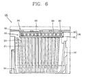
- the air circuit breaker with the arc extinguishing apparatus may comprise a frame 110 having a receiving space 112, a fixed contact 120 disposed inside the frame 110, a movable contact 130 disposed to be in contact with or separated from the fixed contact 120, and an extinguishing apparatus 150, which may include a chamber member 151 disposed in the frame 110 and having an outlet 153 formed at one side thereof, a plurality of grids 171 disposed inside the chamber member 151 to be spaced apart from one another, and a cloth filter member 180 made of fabric and disposed between the outlet 153 and the grids 171 to prevent scattering of fragments which are generated when the grids 171 are melted by arcs.
- the frame 110 may have the receiving space 112 formed therein, and have an open portion formed at an upper end thereof to allow gas to be discharged therethrough.
- the fixed contact 120 may be disposed at one side in the frame 110 in a longitudinal direction.
- the movable contact 130 may be installed at one side of the fixed contact 120 such that the movable contact 130 can be in contact with or separated from the fixed contact 120 by rotating in a longitudinal direction.
- the fixed contact 120 may include a main contact point 122, and an arc contact point 124 formed at one side of the main contact point 122 to be spaced apart from the main contact point 122.
- the movable contact 130 may include a main contact point 132 and an arc contact point 134 formed at one end portion of the movable contact 130 so as to be contactable to the main contact point 122 and the arc contact point 124 of the fixed contact 120, respectively, and a rotational shaft 136 may be disposed at the other end portion of the movable contact 130 such that the movable contact 130 rotates toward or away from the fixed contact 120.
- a first arc runner 141 may be disposed at the fixed contact 120, thus to induce arcs, which occur when the movable contact 130 rotated to be separated from the fixed contact 120, toward the extinguishing apparatus 150.
- a second arc runner 142 may be disposed at a side facing the first arc runner 141 of the extinguishing apparatus 150.
- the extinguishing apparatus 150 may comprise the chamber member 151 having a receiving space and having the outlet 153 formed at one side thereof to allow gas to be discharged therethrough, a plurality of planar grids 171 disposed in the chamber member 151 to be spaced apart from one another, and the cloth filter member 180 made of fabric and disposed between the outlet 153 and the grids 171 to prevent fragments, which are generated from the side of the grids 171, from being discharged (scattered) to the outside through the outlet 153.
- the chamber member 151 which is implemented as an insulating member, may have the receiving space therein.
- the chamber member 151 may have an approximately rectangular parallelepiped having the outlet 153 formed at an upper end thereof.
- the chamber member 151 may be installed at an open area of the frame 110 such that gas discharged through the outlet 153 can be discharged out of the frame 110.
- a plurality of insertion grooves 155 may be formed by being recessed into the chamber member 151 so as to accommodate both sides of the grids 171 therein.
- At one side of the chamber member 151 namely, at one end edge of the chamber member 151 may be disposed the other side of the first arc runner 142 having one end connected to the fixed contact 120.
- the second arc runner 142 may be disposed at the other side edge of the chamber member 151.
- An exhaust cover 161 for covering the outlet 153 may be fixed to the upper side of the chamber member 151 by a plurality of screws 167.
- the exhaust cover 161 which is implemented as an insulating member, may have a rectangular plate shape.
- a plurality of screw holes 165, through which the screws 167 are respectively inserted, may be formed at both short edge areas of the exhaust cover 161.
- a plurality of communication holes 163 connected to the outside may be formed in a central area of the exhaust cover 161 so as to decrease temperature and pressure which have been increased by arcs occurred when contacts are separated from each other.
- the cloth filter member 180 may be installed between the grids 171 and the exhaust cover 161 such that fragments, which are generated when the grids are melted by arcs, can be prevented from being scattered to the outside through the communication holes 163 of the exhaust cover 161.
- the cloth filter member 180 may be composed of a pair of first and second filters 181 and 182, which are disposed to be spaced apart from each other along a direction in which gas is discharged.
- the first filter 181 may be disposed in the chamber member 151 and have an approximately rectangular plate shape to thusly block (shield) upper areas of the grids 171.
- the first filter 181 may be woven by two first wires 185 implemented as a metallic member and arrayed in parallel to each other, and two second wires 186 implemented as a metallic member and arrayed in parallel to each other, the first and second wires 185 and 186 being arrayed to be orthogonal to each other.
- the two first wires 185 and the two second wires 186 may be woven to be curved such that they can alternately be arranged up and down with each other.
- one first wire 185 and one second wire 186 may be provided such that each wire 185 and 186 may be arrayed up and down with each other in an alternate manner.
- the second filter 182 may be woven by the same method as that adapted for the first filter 181.
- the second filter 182 may be configured by using wires having a diameter shorter than that of the wires of the first filter 181 such that air gaps of the second filter 182 can be smaller in size than those of the first filter 181.
- the first filter 181 and the second filter 182 may be woven by using fiber threads, such as synthetic resin.
- a porous plate 193 may be disposed between the first filter 181 and the second filter 182.
- the porous plate 193, which is implemented as a metallic member, may have a rectangular plate shape, and have a plurality of through holes 193 formed through a planar surface thereof. Accordingly, it may be available to avoid a deformation of the first filter 181, and also to improve cooling effect and exhaust function for arcs and gases which are segmented (dispersed, distributed, etc.) and cooled more densely by the first filter 181.
- the first filter 181 and the second filter 182 allow the gas to pass therethrough but prevent the fragments from being scattered therethrough.
- the porous plate 193 supports the first filter 181 and the second filter 181 so as not to be deformed and also facilitate cooling of arcs which have densely been segmented by passing through the first filter 181.
- Fig. 7 is a cross-sectional view showing an air circuit breaker with an arc extinguishing apparatus in accordance with another embodiment of the present invention
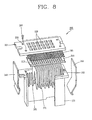
- Fig. 8 is an enlarged perspective view of the extinguishing apparatus of Figure 7
- Fig. 9 is an enlarged cross-sectional view showing main parts of Fig. 7 .
- the same parts as or similar parts to the aforementioned configuration will not be described for the sake of description of drawings, and will be described with reference to the same reference numerals. As shown in Figs.
- the air circuit breaker with the arc extinguishing apparatus may comprise a frame 110 having a receiving space 112, a fixed contact 120 disposed inside the frame 110, a movable contact 130 disposed to be in contact with or separated from the fixed contact 120, and an extinguishing apparatus 150, which may include a chamber member 151 disposed in the frame 110 and having an outlet 153 formed at one side thereof, an exhaust cover 201 disposed to cover the outlet 153 of the chamber member 151, a plurality of grids 171 disposed inside the chamber member 151 to be spaced apart from one another, and a cloth filter member 180 made of fabric and disposed between the exhaust cover 201 and the grids 171 to prevnet scattering of fragments which are generated when the grids 171 are is melted by arcs.
- the chamber member 151 which is implemented as an insulating member, may have a receiving space therein.
- the chamber member 151 may have an approximately rectangular parallelepiped having the outlet 153 formed at an upper end thereof.
- a plurality of insertion grooves 155 may be formed in both long edges in the chamber member 151. Both sides of each grid 171 may be inserted into each insertion groove 155.
- the cloth filter member 180 which is woven by using metallic wires may be disposed between the outlet 153 of the chamber member 151 and the grids 171 so as to prevent scattering of fragments which are generated when the grids 171 are melted by arcs occurred.
- the cloth filter member 180 may be composed of one of the first filter 181 and the second filter 182 described above, in relation to Figs. 2 to 6 .
- the exhaust cover 201 for covering the outlet 153 may be coupled to the outlet 153 of the chamber member 151 by a plurality of screws 207.
- the exhaust cover 201 which is implemented as an insulating member, may have a rectangular planer shape.
- the exhaust cover 201 may include a plurality of screw holes 205 and a plurality of through holes 203 which are formed through the planar surface thereof.
- the through hole 203 the size of which is small and all the same, may be formed in the whole area of the exhaust cover 201 at a constant interval. Accordingly, the cloth filter member 180 may be prevented from being deformed and also internal gas may be allowed to be smoothly discharged through the through holes 203.
- a porous plate 211 which is implemented as an insulating member may be disposed between the cloth filter member 180 and the grids 171.
- the porous plate 211 may have a plurality of through holes 213 formed through a planar surface thereof. Through holes 213 may be formed to correspond to an interval between the grids 171. Accordingly, fragments which are generated due to arcs may be prevented from being scattered toward the outlet 153, and also the arcs may be bypassed.
- the porous plate 211 may be configured in plurality. Any one of the plurality of porous plates 211 may be a porous plate 191 implemented as a metallic member described above, in relation to Figs. 2 to 6 .
- arcs may occur between contact points of the fixed contact 120 and contact points of the movable contact 130.
- the occurred arcs are quickly moved to the extinguishing apparatus 200 via the first arc runner 141, thus to be segmented and cooled by the grids 171.
- the grids 171 may partially be melted by the arcs of high temperature, thereby generating fragments scattered.
- the porous plate 211 as shown in Fig. 9 , can prevent the fragments from being scattered therethrough and also induce arcs to be bypassed for movement.
- the cloth filter member 180 may allow gas to pass therethrough and also prevent the scattering of the fragments which passed through the porous plate 211.
- the exhaust cover 201 may allow gases to be appropriately dispersed to smoothly pass through it, and also support the cloth filter member so as to prevent the deformation of the cloth filter member 180.
- the cloth filter member formed of fabric is disposed at the side of the downstream of the grids, thereby effectively preventing scattering of the fragments which are generated by arcs.
- the fabrication cost can be decreased by using the cloth filter member made of fabric.
- the exhaust cover may be disposed to cover the outlet of the chamber member and the cloth filter member may be disposed between the exhaust cover and the grids, so as to effectively prevent fragments generated due to arcs from being scattered to the outside.
- the porous plate implemented as a metallic member may be disposed at one side of the cloth filter member, to thusly effectively cool and disperse arcs, and to more effectively prevent the fragments generated due to arcs from being discharged to the outside.
- the porous plate implemented as an insulating member may be disposed at one side of the cloth filter member, to thusly effectively control the scattering of arcs, thereby effectively preventing fragments from being scattered to the outside.
Landscapes
- Arc-Extinguishing Devices That Are Switches (AREA)
- Breakers (AREA)
Applications Claiming Priority (1)
| Application Number | Priority Date | Filing Date | Title |
|---|---|---|---|
| KR1020060139140A KR20080062942A (ko) | 2006-12-29 | 2006-12-29 | 기중차단기의 소호장치 |
Publications (2)
| Publication Number | Publication Date |
|---|---|
| EP1939904A2 true EP1939904A2 (fr) | 2008-07-02 |
| EP1939904A3 EP1939904A3 (fr) | 2009-05-20 |
Family
ID=39301169
Family Applications (1)
| Application Number | Title | Priority Date | Filing Date |
|---|---|---|---|
| EP07024416A Withdrawn EP1939904A3 (fr) | 2006-12-29 | 2007-12-17 | Disjoncteur à air avec appareil d'extinction d'ARC |
Country Status (4)
| Country | Link |
|---|---|
| EP (1) | EP1939904A3 (fr) |
| KR (1) | KR20080062942A (fr) |
| CN (1) | CN101211726A (fr) |
| RU (1) | RU2007149300A (fr) |
Cited By (5)
| Publication number | Priority date | Publication date | Assignee | Title |
|---|---|---|---|---|
| CN102005322A (zh) * | 2010-12-10 | 2011-04-06 | 武汉长海电气科技开发有限公司 | 开关电器灭弧室 |
| WO2016133997A1 (fr) * | 2015-02-17 | 2016-08-25 | General Electric Company | Ensemble filtre pour chambre à arc de disjoncteur |
| CN111092007A (zh) * | 2019-12-10 | 2020-05-01 | 上海电器科学研究所(集团)有限公司 | 一种框架式断路器引弧灭弧装置及触头灭弧系统 |
| WO2020169623A1 (fr) * | 2019-02-20 | 2020-08-27 | Eaton Intelligent Power Limited | Dispositif de commutation avec refroidissement efficace de gaz sortants |
| CN113646863A (zh) * | 2019-04-02 | 2021-11-12 | Ls电气株式会社 | 空气断路器的灭弧装置 |
Families Citing this family (8)
| Publication number | Priority date | Publication date | Assignee | Title |
|---|---|---|---|---|
| CN101540248B (zh) * | 2009-03-30 | 2011-04-13 | 常熟开关制造有限公司(原常熟开关厂) | 低压断路器 |
| CN101908442A (zh) * | 2010-08-05 | 2010-12-08 | 无锡新宏泰电器科技股份有限公司 | 新型断路器灭弧结构 |
| KR102520091B1 (ko) * | 2016-03-14 | 2023-04-10 | 엘에스일렉트릭(주) | 복합소호식 초고압 차단기의 소호부 |
| FR3069699B1 (fr) * | 2017-07-26 | 2019-09-06 | Schneider Electric Industries Sas | Dispositif de filtrage de gaz de coupure et appareil de coupure d'un courant electrique comprenant un tel dispositif de filtrage |
| CN107680891B (zh) * | 2017-10-31 | 2020-06-30 | 首瑞(天津)电气设备有限公司 | 一种触头灭弧系统、低压断路器及灭弧系统 |
| KR102549302B1 (ko) * | 2018-07-09 | 2023-06-30 | 엘에스일렉트릭(주) | 배선용 차단기의 아크 소호 장치 |
| KR102275001B1 (ko) * | 2019-10-17 | 2021-07-08 | 엘에스일렉트릭(주) | 아크를 효과적으로 소호할 수 있는 전자 접촉기 |
| CN117727595B (zh) * | 2024-02-07 | 2024-04-26 | 温州华嘉电器有限公司 | 一种断路器灭弧室 |
Citations (3)
| Publication number | Priority date | Publication date | Assignee | Title |
|---|---|---|---|---|
| US3171936A (en) * | 1962-07-27 | 1965-03-02 | Gen Electric | Arc extinguishing structure with venting passage and deflector means |
| US3621169A (en) * | 1970-04-20 | 1971-11-16 | Gen Electric | Electric circuit interrupter with novel arc gas discharge muffle assembly |
| US5889249A (en) * | 1996-06-28 | 1999-03-30 | Schneider Electric Sa | Tightly joined wire mesh deionizing device for a current breaker |
-
2006
- 2006-12-29 KR KR1020060139140A patent/KR20080062942A/ko not_active Application Discontinuation
-
2007
- 2007-12-17 EP EP07024416A patent/EP1939904A3/fr not_active Withdrawn
- 2007-12-26 RU RU2007149300/09A patent/RU2007149300A/ru not_active Application Discontinuation
- 2007-12-28 CN CNA2007103057374A patent/CN101211726A/zh active Pending
Patent Citations (3)
| Publication number | Priority date | Publication date | Assignee | Title |
|---|---|---|---|---|
| US3171936A (en) * | 1962-07-27 | 1965-03-02 | Gen Electric | Arc extinguishing structure with venting passage and deflector means |
| US3621169A (en) * | 1970-04-20 | 1971-11-16 | Gen Electric | Electric circuit interrupter with novel arc gas discharge muffle assembly |
| US5889249A (en) * | 1996-06-28 | 1999-03-30 | Schneider Electric Sa | Tightly joined wire mesh deionizing device for a current breaker |
Cited By (12)
| Publication number | Priority date | Publication date | Assignee | Title |
|---|---|---|---|---|
| CN102005322A (zh) * | 2010-12-10 | 2011-04-06 | 武汉长海电气科技开发有限公司 | 开关电器灭弧室 |
| CN102005322B (zh) * | 2010-12-10 | 2013-01-30 | 武汉长海电气科技开发有限公司 | 开关电器灭弧室 |
| WO2016133997A1 (fr) * | 2015-02-17 | 2016-08-25 | General Electric Company | Ensemble filtre pour chambre à arc de disjoncteur |
| CN107210149A (zh) * | 2015-02-17 | 2017-09-26 | 通用电气公司 | 用于断路器电弧室的过滤器组件 |
| US10134537B2 (en) | 2015-02-17 | 2018-11-20 | Abb Schweiz Ag | Filter assembly for a circuit breaker arc chamber |
| CN107210149B (zh) * | 2015-02-17 | 2019-12-27 | Abb瑞士股份有限公司 | 用于断路器电弧室的过滤器组件 |
| WO2020169623A1 (fr) * | 2019-02-20 | 2020-08-27 | Eaton Intelligent Power Limited | Dispositif de commutation avec refroidissement efficace de gaz sortants |
| US11869741B2 (en) | 2019-02-20 | 2024-01-09 | Eaton Intelligent Power Limited | Switching device with effective cooling of outflowing gases |
| CN113646863A (zh) * | 2019-04-02 | 2021-11-12 | Ls电气株式会社 | 空气断路器的灭弧装置 |
| CN113646863B (zh) * | 2019-04-02 | 2024-06-11 | Ls电气株式会社 | 空气断路器的灭弧装置 |
| CN111092007A (zh) * | 2019-12-10 | 2020-05-01 | 上海电器科学研究所(集团)有限公司 | 一种框架式断路器引弧灭弧装置及触头灭弧系统 |
| CN111092007B (zh) * | 2019-12-10 | 2022-07-01 | 上海电器科学研究所(集团)有限公司 | 一种框架式断路器引弧灭弧装置及触头灭弧系统 |
Also Published As
| Publication number | Publication date |
|---|---|
| EP1939904A3 (fr) | 2009-05-20 |
| RU2007149300A (ru) | 2009-07-10 |
| CN101211726A (zh) | 2008-07-02 |
| KR20080062942A (ko) | 2008-07-03 |
Similar Documents
| Publication | Publication Date | Title |
|---|---|---|
| EP1939904A2 (fr) | Disjoncteur à air avec appareil d'extinction d'ARC | |
| EP2064718B1 (fr) | Isolateur d'isolation gazeuse, et ensemble boîte de soufflage et dispositif de commutation électrique l'utilisant | |
| US7705263B2 (en) | Arc chute assembly for a circuit breaker | |
| US7488915B2 (en) | ARC baffle, and ARC chute assembly and electrical switching apparatus employing the same | |
| US8772665B2 (en) | Circuit breaker with arc extinguishing mechanism | |
| US6762389B1 (en) | Gas discharge filter for electrical switching apparatus | |
| US9362065B2 (en) | Molded case circuit breaker | |
| US10522310B2 (en) | Extinguishing gas filtering device and electric current switchgear comprising such a filtering device | |
| US10163598B2 (en) | Extinguishing unit of molded case circuit breaker | |
| US20150270075A1 (en) | Modular gas exhaust assembly for a circuit breaker | |
| EP4333013A1 (fr) | Unité d'extinction d'arc et disjoncteur à air la comprenant | |
| RU2649969C2 (ru) | Камера гашения дуги для устройства электрической защиты и устройство электрической защиты, содержащее ее | |
| US20200219683A1 (en) | Change-over switch | |
| CN109830392A (zh) | 低压多极断路器 | |
| CN113646863B (zh) | 空气断路器的灭弧装置 | |
| EP0195862B1 (fr) | Chambre d'extinction d'arc pour un coupe-circuit | |
| EP2618354B1 (fr) | Ensemble de boîte de soufflage d'arc et son procédé de fabrication | |
| US11869741B2 (en) | Switching device with effective cooling of outflowing gases | |
| EP4220676A1 (fr) | Disjoncteur | |
| CN218160248U (zh) | 一种断路器 | |
| JPH08315706A (ja) | 消弧装置 | |
| CN212874379U (zh) | 用于低压断路器的端子夹具覆盖装置及对应的低压断路器 | |
| CN114360980A (zh) | 灭弧装置和断路器 |
Legal Events
| Date | Code | Title | Description |
|---|---|---|---|
| PUAI | Public reference made under article 153(3) epc to a published international application that has entered the european phase |
Free format text: ORIGINAL CODE: 0009012 |
|
| 17P | Request for examination filed |
Effective date: 20071217 |
|
| AK | Designated contracting states |
Kind code of ref document: A2 Designated state(s): AT BE BG CH CY CZ DE DK EE ES FI FR GB GR HU IE IS IT LI LT LU LV MC MT NL PL PT RO SE SI SK TR |
|
| AX | Request for extension of the european patent |
Extension state: AL BA HR MK RS |
|
| PUAL | Search report despatched |
Free format text: ORIGINAL CODE: 0009013 |
|
| AK | Designated contracting states |
Kind code of ref document: A3 Designated state(s): AT BE BG CH CY CZ DE DK EE ES FI FR GB GR HU IE IS IT LI LT LU LV MC MT NL PL PT RO SE SI SK TR |
|
| AX | Request for extension of the european patent |
Extension state: AL BA HR MK RS |
|
| STAA | Information on the status of an ep patent application or granted ep patent |
Free format text: STATUS: THE APPLICATION HAS BEEN WITHDRAWN |
|
| 18W | Application withdrawn |
Effective date: 20090819 |