EP1939566A1 - Articles for use with highly reactive alloys - Google Patents
Articles for use with highly reactive alloys Download PDFInfo
- Publication number
- EP1939566A1 EP1939566A1 EP07122388A EP07122388A EP1939566A1 EP 1939566 A1 EP1939566 A1 EP 1939566A1 EP 07122388 A EP07122388 A EP 07122388A EP 07122388 A EP07122388 A EP 07122388A EP 1939566 A1 EP1939566 A1 EP 1939566A1
- Authority
- EP
- European Patent Office
- Prior art keywords
- protective layer
- highly reactive
- crucible
- article according
- alloy
- Prior art date
- Legal status (The legal status is an assumption and is not a legal conclusion. Google has not performed a legal analysis and makes no representation as to the accuracy of the status listed.)
- Withdrawn
Links
- 229910045601 alloy Inorganic materials 0.000 title claims abstract description 58
- 239000000956 alloy Substances 0.000 title claims abstract description 58
- 239000011241 protective layer Substances 0.000 claims abstract description 36
- OKTJSMMVPCPJKN-UHFFFAOYSA-N Carbon Chemical compound [C] OKTJSMMVPCPJKN-UHFFFAOYSA-N 0.000 claims abstract description 34
- 230000008018 melting Effects 0.000 claims abstract description 27
- 238000002844 melting Methods 0.000 claims abstract description 27
- 229910002804 graphite Inorganic materials 0.000 claims abstract description 25
- 239000010439 graphite Substances 0.000 claims abstract description 25
- 239000011888 foil Substances 0.000 claims description 24
- 239000011248 coating agent Substances 0.000 claims description 11
- 238000000576 coating method Methods 0.000 claims description 11
- 229910052758 niobium Inorganic materials 0.000 claims description 9
- 239000010955 niobium Substances 0.000 claims description 9
- GUCVJGMIXFAOAE-UHFFFAOYSA-N niobium atom Chemical compound [Nb] GUCVJGMIXFAOAE-UHFFFAOYSA-N 0.000 claims description 9
- ZOKXTWBITQBERF-UHFFFAOYSA-N Molybdenum Chemical compound [Mo] ZOKXTWBITQBERF-UHFFFAOYSA-N 0.000 claims description 6
- 229910052750 molybdenum Inorganic materials 0.000 claims description 6
- 239000011733 molybdenum Substances 0.000 claims description 6
- 229910052715 tantalum Inorganic materials 0.000 claims description 6
- GUVRBAGPIYLISA-UHFFFAOYSA-N tantalum atom Chemical compound [Ta] GUVRBAGPIYLISA-UHFFFAOYSA-N 0.000 claims description 6
- WFKWXMTUELFFGS-UHFFFAOYSA-N tungsten Chemical compound [W] WFKWXMTUELFFGS-UHFFFAOYSA-N 0.000 claims description 6
- 229910052721 tungsten Inorganic materials 0.000 claims description 6
- 239000010937 tungsten Substances 0.000 claims description 6
- RTAQQCXQSZGOHL-UHFFFAOYSA-N Titanium Chemical compound [Ti] RTAQQCXQSZGOHL-UHFFFAOYSA-N 0.000 claims description 5
- 229910052719 titanium Inorganic materials 0.000 claims description 5
- 239000010936 titanium Substances 0.000 claims description 5
- PXHVJJICTQNCMI-UHFFFAOYSA-N Nickel Chemical compound [Ni] PXHVJJICTQNCMI-UHFFFAOYSA-N 0.000 claims description 4
- 229910052735 hafnium Inorganic materials 0.000 claims description 2
- VBJZVLUMGGDVMO-UHFFFAOYSA-N hafnium atom Chemical compound [Hf] VBJZVLUMGGDVMO-UHFFFAOYSA-N 0.000 claims description 2
- 229910052741 iridium Inorganic materials 0.000 claims description 2
- GKOZUEZYRPOHIO-UHFFFAOYSA-N iridium atom Chemical compound [Ir] GKOZUEZYRPOHIO-UHFFFAOYSA-N 0.000 claims description 2
- 229910052759 nickel Inorganic materials 0.000 claims description 2
- 229910052702 rhenium Inorganic materials 0.000 claims description 2
- WUAPFZMCVAUBPE-UHFFFAOYSA-N rhenium atom Chemical compound [Re] WUAPFZMCVAUBPE-UHFFFAOYSA-N 0.000 claims description 2
- 238000011109 contamination Methods 0.000 description 11
- 229910052799 carbon Inorganic materials 0.000 description 9
- OQPDWFJSZHWILH-UHFFFAOYSA-N [Al].[Al].[Al].[Ti] Chemical compound [Al].[Al].[Al].[Ti] OQPDWFJSZHWILH-UHFFFAOYSA-N 0.000 description 8
- 229910021324 titanium aluminide Inorganic materials 0.000 description 8
- 229910001069 Ti alloy Inorganic materials 0.000 description 6
- 230000006698 induction Effects 0.000 description 5
- 238000010438 heat treatment Methods 0.000 description 4
- 230000008901 benefit Effects 0.000 description 3
- 239000010410 layer Substances 0.000 description 3
- 229910052751 metal Inorganic materials 0.000 description 3
- 239000002184 metal Substances 0.000 description 3
- 229910000753 refractory alloy Inorganic materials 0.000 description 3
- QVGXLLKOCUKJST-UHFFFAOYSA-N atomic oxygen Chemical compound [O] QVGXLLKOCUKJST-UHFFFAOYSA-N 0.000 description 2
- 238000006243 chemical reaction Methods 0.000 description 2
- 239000000155 melt Substances 0.000 description 2
- 229910052760 oxygen Inorganic materials 0.000 description 2
- 239000001301 oxygen Substances 0.000 description 2
- 229910000951 Aluminide Inorganic materials 0.000 description 1
- ZOXJGFHDIHLPTG-UHFFFAOYSA-N Boron Chemical compound [B] ZOXJGFHDIHLPTG-UHFFFAOYSA-N 0.000 description 1
- VYZAMTAEIAYCRO-UHFFFAOYSA-N Chromium Chemical compound [Cr] VYZAMTAEIAYCRO-UHFFFAOYSA-N 0.000 description 1
- NPXOKRUENSOPAO-UHFFFAOYSA-N Raney nickel Chemical compound [Al].[Ni] NPXOKRUENSOPAO-UHFFFAOYSA-N 0.000 description 1
- XUIMIQQOPSSXEZ-UHFFFAOYSA-N Silicon Chemical compound [Si] XUIMIQQOPSSXEZ-UHFFFAOYSA-N 0.000 description 1
- 238000010521 absorption reaction Methods 0.000 description 1
- 229910052782 aluminium Inorganic materials 0.000 description 1
- XAGFODPZIPBFFR-UHFFFAOYSA-N aluminium Chemical compound [Al] XAGFODPZIPBFFR-UHFFFAOYSA-N 0.000 description 1
- 230000004888 barrier function Effects 0.000 description 1
- 230000015572 biosynthetic process Effects 0.000 description 1
- 229910052796 boron Inorganic materials 0.000 description 1
- 239000000919 ceramic Substances 0.000 description 1
- 229910052804 chromium Inorganic materials 0.000 description 1
- 239000011651 chromium Substances 0.000 description 1
- 239000007788 liquid Substances 0.000 description 1
- 239000007791 liquid phase Substances 0.000 description 1
- WPBNNNQJVZRUHP-UHFFFAOYSA-L manganese(2+);methyl n-[[2-(methoxycarbonylcarbamothioylamino)phenyl]carbamothioyl]carbamate;n-[2-(sulfidocarbothioylamino)ethyl]carbamodithioate Chemical compound [Mn+2].[S-]C(=S)NCCNC([S-])=S.COC(=O)NC(=S)NC1=CC=CC=C1NC(=S)NC(=O)OC WPBNNNQJVZRUHP-UHFFFAOYSA-L 0.000 description 1
- 150000002739 metals Chemical class 0.000 description 1
- 238000000034 method Methods 0.000 description 1
- 229910000907 nickel aluminide Inorganic materials 0.000 description 1
- 230000009257 reactivity Effects 0.000 description 1
- 230000009467 reduction Effects 0.000 description 1
- 229910021332 silicide Inorganic materials 0.000 description 1
- FVBUAEGBCNSCDD-UHFFFAOYSA-N silicide(4-) Chemical compound [Si-4] FVBUAEGBCNSCDD-UHFFFAOYSA-N 0.000 description 1
- 229910052710 silicon Inorganic materials 0.000 description 1
- 239000010703 silicon Substances 0.000 description 1
- 210000003625 skull Anatomy 0.000 description 1
- 239000007921 spray Substances 0.000 description 1
- 238000007740 vapor deposition Methods 0.000 description 1
- 230000035899 viability Effects 0.000 description 1
Images

Classifications
-
- F—MECHANICAL ENGINEERING; LIGHTING; HEATING; WEAPONS; BLASTING
- F27—FURNACES; KILNS; OVENS; RETORTS
- F27B—FURNACES, KILNS, OVENS OR RETORTS IN GENERAL; OPEN SINTERING OR LIKE APPARATUS
- F27B14/00—Crucible or pot furnaces
- F27B14/08—Details specially adapted for crucible or pot furnaces
- F27B14/10—Crucibles
-
- C—CHEMISTRY; METALLURGY
- C22—METALLURGY; FERROUS OR NON-FERROUS ALLOYS; TREATMENT OF ALLOYS OR NON-FERROUS METALS
- C22B—PRODUCTION AND REFINING OF METALS; PRETREATMENT OF RAW MATERIALS
- C22B34/00—Obtaining refractory metals
- C22B34/10—Obtaining titanium, zirconium or hafnium
- C22B34/12—Obtaining titanium or titanium compounds from ores or scrap by metallurgical processing; preparation of titanium compounds from other titanium compounds see C01G23/00 - C01G23/08
- C22B34/1295—Refining, melting, remelting, working up of titanium
-
- C—CHEMISTRY; METALLURGY
- C22—METALLURGY; FERROUS OR NON-FERROUS ALLOYS; TREATMENT OF ALLOYS OR NON-FERROUS METALS
- C22B—PRODUCTION AND REFINING OF METALS; PRETREATMENT OF RAW MATERIALS
- C22B9/00—General processes of refining or remelting of metals; Apparatus for electroslag or arc remelting of metals
- C22B9/003—General processes of refining or remelting of metals; Apparatus for electroslag or arc remelting of metals by induction
-
- Y—GENERAL TAGGING OF NEW TECHNOLOGICAL DEVELOPMENTS; GENERAL TAGGING OF CROSS-SECTIONAL TECHNOLOGIES SPANNING OVER SEVERAL SECTIONS OF THE IPC; TECHNICAL SUBJECTS COVERED BY FORMER USPC CROSS-REFERENCE ART COLLECTIONS [XRACs] AND DIGESTS
- Y02—TECHNOLOGIES OR APPLICATIONS FOR MITIGATION OR ADAPTATION AGAINST CLIMATE CHANGE
- Y02P—CLIMATE CHANGE MITIGATION TECHNOLOGIES IN THE PRODUCTION OR PROCESSING OF GOODS
- Y02P10/00—Technologies related to metal processing
- Y02P10/25—Process efficiency
Definitions
- Embodiments described herein generally relate to articles for use with highly reactive alloys. More particularly, embodiments herein generally describe graphite crucibles that can be used to melt highly reactive alloys such as titanium aluminide.
- Induction melting generally involves heating a metal in a crucible made from a nonconductive refractory alloy oxide until the charge of metal within the crucible is melted down to liquid form.
- vacuum induction melting using cold wall or graphite crucibles is typically employed.
- Embodiments herein generally relate to articles for use with highly reactive alloys comprising a graphite crucible having an interior, and at least a first protective layer applied to the interior of the graphite crucible.
- Embodiments herein also generally relate to articles for use with highly reactive alloys comprising a graphite crucible having an interior, at least a first protective layer applied to the interior of the graphite crucible, and at least a second protective layer applied to the first protective layer.
- Embodiments described herein generally relate to articles having at least one protective layer for use with highly reactive alloys.
- embodiments herein relate to graphite crucibles having at least one protective layer comprising either a foil liner or a carbide coating as set forth below.
- FIG. 1 illustrates one embodiment of an acceptable graphite crucible 10 for use herein.
- Graphite crucible 10 may be any graphite crucible known to those skilled in the art suitable for induction melting.
- Graphite crucible 10 can have an interior 12 for containing the alloy to be melted and an exterior 14.
- Graphite crucible 10 may be used to melt highly reactive alloys such as, for example, those including the elements titanium, hafnium, iridium or rhenium, as well as advanced alloys including niobium, for example niobium silicide, or nickel, for example nickel aluminide.
- the highly reactive alloy may comprise titanium aluminide (TiAl), and in particular a TiAl alloy containing a high melting point alloy elements such as niobium, tantalum, tungsten, and molybdenum.
- the previously mentioned titanium alloys may generally comprise from about 61 wt % to about 71 wt % titanium, from about 25 wt % to about 35 wt % aluminum, with the remainder of the alloy comprising the high melting point alloy elements as well as small amounts of any of carbon, boron, chromium, silicon, manganese, and combinations thereof.
- highly reactive alloys refers to alloys having a high free energy of absorption for oxygen in the liquid phase.
- embodiments herein can reduce the occurrence of contamination of the melted alloy because of the presence of at least a first protective layer 16 applied to interior 12 of crucible 10, as shown generally in FIG. 2 . More particularly, the presence of first protective layer can reduce carbon contamination of the melted alloy to such a degree that the melted alloy may comprise up to about 0.015 wt % carbon. This includes both any carbon that may be present in the highly reactive alloy and any carbon resulting from the reaction of the graphite crucible.
- First protective layer 16 may comprise a foil liner or a carbide coating. More specifically, in one embodiment, first protective layer 16 can comprise a foil liner fabricated from up to about 100% of at least one of the previously referenced high melting point alloy elements, which can include niobium, tantalum, tungsten, and molybdenum.
- the foil liner may be press molded into interior 12 of crucible 10 or it may be preformed and dropped into place. Once in position, the foil liner may be held in place by mechanical deformation about the crucible.
- the foil liner may have any desired thickness
- the foil liner can have a thickness of from about 0.005mm to about 2mm, in another embodiment from about 0.005mm to about 1.5mm, and in one embodiment about 0.005mm to about 1mm.
- the foil liner can have a thickness of about 0.025mm.
- the desired highly reactive alloy such as TiAl
- the desired highly reactive alloy may be placed into the foil lined crucible and melted, generally at a temperature of from about 1370°C (about 2500°F) to about 1700°C (about 3100°F).
- the resulting melted alloy can contain a reduced amount of carbon contaminates when compared to the amount of contaminates present in alloys melted in non-lined crucibles.
- the foil liner can protect the melted alloy against contamination in two ways. First, the foil liner can serve as a barrier to contamination by helping to prevent the melted alloy from contacting the graphite crucible in the first instance. Second, the foil liner can serve as a sacrificial layer such that if a portion of the foil liner melts from exposure to the high temperatures, it will not contaminate the melted alloy since the foil liner is comprised of at least one of the high melting point alloy elements contained in the melted alloy itself.
- the foil liner melts upon exposure to the high temperature, it will result in about less than or equal to the specification limit, +/- 0.1 wt % of niobium, tantalum, tungsten or molybdenum being added to the melted alloy in addition to that initially present therein.
- high melting point alloy element selected to make the foil liner should be the same as the high melting point alloy element having the highest melting point present in the highly reactive alloy being melted.
- first protective layer 16 can comprise a carbide coating formed by applying at least one of the previously referenced high melting point alloy elements, that is niobium, tantalum, tungsten, and molybdenum, to interior 12 of crucible 10 followed by heat treatment thereof. More specifically, the selected high melting point alloy element(s) may be applied to interior 12 of crucible 10 using any common method known to those skilled in the art, such as vapor deposition or air plasma spray for example. Once applied, the high melting point alloy element(s) can be heat treated in a carborizing atmosphere by using vacuum heat treatment or by heating the crucible containing the high melting point alloy element in a reducing atmosphere to generate a carbide coating on interior 12 of crucible 10.
- the high melting point alloy element(s) can be heat treated in a carborizing atmosphere by using vacuum heat treatment or by heating the crucible containing the high melting point alloy element in a reducing atmosphere to generate a carbide coating on interior 12 of crucible 10.
- the resulting melted alloy can again contain relatively fewer contaminates compared to melted alloys prepared in non-coated crucibles.
- the amount of carbon contamination resulting from the reaction of the highly reactive alloy with the graphite crucible can be reduced by at least about 50%, and in another embodiment from about 60% to about 99%, and in yet another embodiment from about 75% to about 99% when compared to the contamination present in non-coated crucibles. This reduction in contamination can be attributed to reduced contact between the highly reactive alloy and the graphite crucible.
- graphite crucible 10 may comprise at least first protective layer 16 and a second protective layer 18. More specifically, if first protective layer 16 comprises a foil liner, then second protective layer 18 can comprise a carbide coating. Alternately, if first protective layer 16 comprises a carbide coating, then second protective layer 18 may comprise a foil layer. Regardless of which of first protective layer 16 or second protective layer 18 is the foil layer or carbide coating, both can be applied in the manner described previously.
- first protective layer 16 and second protective layer 18 may be desirable to utilize both first protective layer 16 and second protective layer 18 because, in addition to the previously described benefits provided by each independently, together the two protective layers can help to extend the use life of crucible 10.
Landscapes
- Engineering & Computer Science (AREA)
- Chemical & Material Sciences (AREA)
- Mechanical Engineering (AREA)
- Manufacturing & Machinery (AREA)
- Organic Chemistry (AREA)
- Metallurgy (AREA)
- Materials Engineering (AREA)
- Life Sciences & Earth Sciences (AREA)
- Geology (AREA)
- General Life Sciences & Earth Sciences (AREA)
- Environmental & Geological Engineering (AREA)
- General Engineering & Computer Science (AREA)
- Crucibles And Fluidized-Bed Furnaces (AREA)
- Physical Vapour Deposition (AREA)
- Manufacture And Refinement Of Metals (AREA)
Abstract
Description
- Embodiments described herein generally relate to articles for use with highly reactive alloys. More particularly, embodiments herein generally describe graphite crucibles that can be used to melt highly reactive alloys such as titanium aluminide.
- Induction melting generally involves heating a metal in a crucible made from a nonconductive refractory alloy oxide until the charge of metal within the crucible is melted down to liquid form. When melting highly reactive metals such as titanium or titanium alloys, vacuum induction melting using cold wall or graphite crucibles is typically employed.
- However, difficulties can arise when melting these highly reactive alloys due to the reactivity of the elements in the alloy at the temperatures needed for melting to occur. As previously mentioned, while most induction melting systems use refractory alloy oxides for crucibles in the induction furnace, alloys such as titanium aluminide (TiAl) are so highly reactive that they can attack the refractory alloys present in the crucible and contaminate the titanium alloy. For example, ceramic crucibles are typically avoided because the highly reactive alloys can break down the crucible and contaminate the titanium alloy with oxygen. Similarly, if graphite crucibles are employed, both the titanium and the aluminide can dissolve large quantities of carbon from the crucible into the titanium alloy, thereby resulting in contamination. Such contamination results in the loss of mechanical properties of the titanium alloy.
- Moreover, while cold crucible melting offers metallurgical advantages for the processing of the highly reactive alloys described previously, it also has a number of technical and economic limitations including low superheat, yield losses due to skull formation, high power requirements and a limited melt capacity. These limitations can restrict its commercial viability.
- Accordingly, there remains a need for articles for use in melting highly reactive alloys that are less susceptible to contamination and pose fewer technical and economic limitations than current applications.
- Embodiments herein generally relate to articles for use with highly reactive alloys comprising a graphite crucible having an interior, and at least a first protective layer applied to the interior of the graphite crucible.
- Embodiments herein also generally relate to articles for use with highly reactive alloys comprising a graphite crucible having an interior, at least a first protective layer applied to the interior of the graphite crucible, and at least a second protective layer applied to the first protective layer.
- These and other features, aspects and advantages will become evident to those skilled in the art from the following disclosure.
- While the specification concludes with claims particularly pointing out and distinctly claiming the invention, it is believed that the embodiments set forth herein will be better understood from the following description in conjunction with the accompanying figures, in which like reference numerals identify like elements.
-
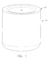
FIG. 1 is a schematic perspective view of one embodiment of a crucible in accordance with the description herein; -
FIG. 2 is a schematic cross-sectional view of one embodiment of a crucible having at least one protective layer in accordance with the description herein; and -
FIG. 3 is a schematic cross-sectional view of one embodiment of a crucible having at least a first and second protective layer in accordance with the description herein. - Embodiments described herein generally relate to articles having at least one protective layer for use with highly reactive alloys. In particular, embodiments herein relate to graphite crucibles having at least one protective layer comprising either a foil liner or a carbide coating as set forth below.
- Turning to the figures,
FIG. 1 illustrates one embodiment of anacceptable graphite crucible 10 for use herein. Graphite crucible 10 may be any graphite crucible known to those skilled in the art suitable for induction melting. Graphite crucible 10 can have aninterior 12 for containing the alloy to be melted and anexterior 14. - Graphite crucible 10 may be used to melt highly reactive alloys such as, for example, those including the elements titanium, hafnium, iridium or rhenium, as well as advanced alloys including niobium, for example niobium silicide, or nickel, for example nickel aluminide. In one embodiment, the highly reactive alloy may comprise titanium aluminide (TiAl), and in particular a TiAl alloy containing a high melting point alloy elements such as niobium, tantalum, tungsten, and molybdenum. The previously mentioned titanium alloys may generally comprise from about 61 wt % to about 71 wt % titanium, from about 25 wt % to about 35 wt % aluminum, with the remainder of the alloy comprising the high melting point alloy elements as well as small amounts of any of carbon, boron, chromium, silicon, manganese, and combinations thereof. As used herein, "highly reactive alloys" refers to alloys having a high free energy of absorption for oxygen in the liquid phase. In contrast to the previously described carbon contamination issues that can arise when using graphite crucibles to melt such highly reactive alloys, embodiments herein can reduce the occurrence of contamination of the melted alloy because of the presence of at least a first
protective layer 16 applied tointerior 12 ofcrucible 10, as shown generally inFIG. 2 . More particularly, the presence of first protective layer can reduce carbon contamination of the melted alloy to such a degree that the melted alloy may comprise up to about 0.015 wt % carbon. This includes both any carbon that may be present in the highly reactive alloy and any carbon resulting from the reaction of the graphite crucible. - First
protective layer 16 may comprise a foil liner or a carbide coating. More specifically, in one embodiment, firstprotective layer 16 can comprise a foil liner fabricated from up to about 100% of at least one of the previously referenced high melting point alloy elements, which can include niobium, tantalum, tungsten, and molybdenum. The foil liner may be press molded intointerior 12 ofcrucible 10 or it may be preformed and dropped into place. Once in position, the foil liner may be held in place by mechanical deformation about the crucible. While the foil liner may have any desired thickness, in one embodiment, the foil liner can have a thickness of from about 0.005mm to about 2mm, in another embodiment from about 0.005mm to about 1.5mm, and in one embodiment about 0.005mm to about 1mm. In yet another embodiment, the foil liner can have a thickness of about 0.025mm. At this point, the desired highly reactive alloy, such as TiAl, may be placed into the foil lined crucible and melted, generally at a temperature of from about 1370°C (about 2500°F) to about 1700°C (about 3100°F). - As previously described, the resulting melted alloy can contain a reduced amount of carbon contaminates when compared to the amount of contaminates present in alloys melted in non-lined crucibles. This is because the foil liner can protect the melted alloy against contamination in two ways. First, the foil liner can serve as a barrier to contamination by helping to prevent the melted alloy from contacting the graphite crucible in the first instance. Second, the foil liner can serve as a sacrificial layer such that if a portion of the foil liner melts from exposure to the high temperatures, it will not contaminate the melted alloy since the foil liner is comprised of at least one of the high melting point alloy elements contained in the melted alloy itself. In general, if the foil liner melts upon exposure to the high temperature, it will result in about less than or equal to the specification limit, +/- 0.1 wt % of niobium, tantalum, tungsten or molybdenum being added to the melted alloy in addition to that initially present therein. Those skilled in the art will understand that high melting point alloy element selected to make the foil liner should be the same as the high melting point alloy element having the highest melting point present in the highly reactive alloy being melted.
- In another embodiment, first
protective layer 16 can comprise a carbide coating formed by applying at least one of the previously referenced high melting point alloy elements, that is niobium, tantalum, tungsten, and molybdenum, tointerior 12 ofcrucible 10 followed by heat treatment thereof. More specifically, the selected high melting point alloy element(s) may be applied tointerior 12 ofcrucible 10 using any common method known to those skilled in the art, such as vapor deposition or air plasma spray for example. Once applied, the high melting point alloy element(s) can be heat treated in a carborizing atmosphere by using vacuum heat treatment or by heating the crucible containing the high melting point alloy element in a reducing atmosphere to generate a carbide coating oninterior 12 ofcrucible 10. When a highly reactive alloy, such as TiAl, is melted incrucible 10, the resulting melted alloy can again contain relatively fewer contaminates compared to melted alloys prepared in non-coated crucibles. In one embodiment, the amount of carbon contamination resulting from the reaction of the highly reactive alloy with the graphite crucible can be reduced by at least about 50%, and in another embodiment from about 60% to about 99%, and in yet another embodiment from about 75% to about 99% when compared to the contamination present in non-coated crucibles. This reduction in contamination can be attributed to reduced contact between the highly reactive alloy and the graphite crucible. - In yet another embodiment, graphite crucible 10 may comprise at least first
protective layer 16 and a secondprotective layer 18. More specifically, if firstprotective layer 16 comprises a foil liner, then secondprotective layer 18 can comprise a carbide coating. Alternately, if firstprotective layer 16 comprises a carbide coating, then secondprotective layer 18 may comprise a foil layer. Regardless of which of firstprotective layer 16 or secondprotective layer 18 is the foil layer or carbide coating, both can be applied in the manner described previously. - It may be desirable to utilize both first
protective layer 16 and secondprotective layer 18 because, in addition to the previously described benefits provided by each independently, together the two protective layers can help to extend the use life ofcrucible 10. - This written description uses examples to disclose the invention, including the best mode, and also to enable any person skilled in the art to make and use the invention. The patentable scope of the invention is defined by the claims, and may include other examples that occur to those skilled in the art. Such other examples are intended to be within the scope of the claims if they have structural elements that do not differ from the literal language of the claims, or if they include equivalent structural elements with insubstantial differences from the literal language of the claims.
Claims (10)
- An article for use with highly reactive alloys comprising: a graphite crucible (10) having an interior (12); and at least a first protective layer (16) applied to the interior (12) of the graphite crucible (10).
- An article according to claim 1 further comprising: at least a second protective layer (18) applied to the first protective layer (16).
- An article according to claim 1 or claim 2 wherein the graphite crucible (10) having at least the first protective layer (16) is used for melting highly reactive alloys selected from the group consisting of titanium, niobium, nickel, hafnium, iridium and rhenium.
- An article according to any one of claims 1, 2 or 3 wherein the first protective layer (16) comprises a foil liner having a thickness of from about 0.005mm to about 2mm.
- An article according to any one of claims 1, 2 or 3 wherein the first protective layer (16) comprises a carbide coating.
- An article according to claim 2 wherein the first protective layer (16) comprises a foil liner and the second protective layer (180 comprises a carbide coating.
- An article according to claim 2 wherein the first protective layer (16) comprises a carbide coating and the second protective layer (18) comprises a foil liner.
- An article according to any one of claims 4, 6 or 7 wherein the foil liner is fabricated from a high melting point alloy element selected from the group consisting of niobium, tantalum, tungsten, and molybdenum.
- An article according to any one of claims 5, 6 or 7 wherein the carbide coating is formed by applying a high melting point alloy element selected from the group consisting of niobium, tantalum, tungsten, and molybdenum, to the interior of the crucible and heat treating the high melting point alloy element in a carborizing atmosphere.
- An article according to any one of claims 4, 6, 7 or 8 wherein the foil liner is fabricated from the high melting point alloy element in the highly reactive alloy that has the highest melting point.
Applications Claiming Priority (1)
| Application Number | Priority Date | Filing Date | Title |
|---|---|---|---|
| US11/646,004 US7790101B2 (en) | 2006-12-27 | 2006-12-27 | Articles for use with highly reactive alloys |
Publications (1)
| Publication Number | Publication Date |
|---|---|
| EP1939566A1 true EP1939566A1 (en) | 2008-07-02 |
Family
ID=39110775
Family Applications (1)
| Application Number | Title | Priority Date | Filing Date |
|---|---|---|---|
| EP07122388A Withdrawn EP1939566A1 (en) | 2006-12-27 | 2007-12-05 | Articles for use with highly reactive alloys |
Country Status (5)
| Country | Link |
|---|---|
| US (1) | US7790101B2 (en) |
| EP (1) | EP1939566A1 (en) |
| JP (1) | JP2009115441A (en) |
| CN (1) | CN101210290B (en) |
| TW (1) | TW200839166A (en) |
Families Citing this family (23)
| Publication number | Priority date | Publication date | Assignee | Title |
|---|---|---|---|---|
| ATE539823T1 (en) * | 2008-03-05 | 2012-01-15 | Southwire Co | ULTRASONIC PROBE WITH NIOBIUM PROTECTIVE LAYER |
| CN101839643A (en) * | 2009-03-20 | 2010-09-22 | 通用电气公司 | Enhancement type fire-proof crucible for smelting titanium alloy |
| US8574336B2 (en) | 2010-04-09 | 2013-11-05 | Southwire Company | Ultrasonic degassing of molten metals |
| US8652397B2 (en) | 2010-04-09 | 2014-02-18 | Southwire Company | Ultrasonic device with integrated gas delivery system |
| CN101984321B (en) * | 2010-11-23 | 2012-05-23 | 北京科技大学 | Method for fabricating crucible pattern die for directional solidification of titanium aluminum alloy |
| US8858697B2 (en) | 2011-10-28 | 2014-10-14 | General Electric Company | Mold compositions |
| US9011205B2 (en) | 2012-02-15 | 2015-04-21 | General Electric Company | Titanium aluminide article with improved surface finish |
| CN102586891B (en) * | 2012-02-28 | 2015-09-30 | 浙江上城科技有限公司 | A kind of lining combined type high-temperature resisting crucible |
| US8932518B2 (en) | 2012-02-29 | 2015-01-13 | General Electric Company | Mold and facecoat compositions |
| US10597756B2 (en) | 2012-03-24 | 2020-03-24 | General Electric Company | Titanium aluminide intermetallic compositions |
| US8906292B2 (en) | 2012-07-27 | 2014-12-09 | General Electric Company | Crucible and facecoat compositions |
| US8708033B2 (en) | 2012-08-29 | 2014-04-29 | General Electric Company | Calcium titanate containing mold compositions and methods for casting titanium and titanium aluminide alloys |
| CN103008634B (en) * | 2012-11-16 | 2015-04-08 | 云南钛业股份有限公司 | Method for smelting by using titanium sponge protective container |
| US8992824B2 (en) | 2012-12-04 | 2015-03-31 | General Electric Company | Crucible and extrinsic facecoat compositions |
| US9592548B2 (en) | 2013-01-29 | 2017-03-14 | General Electric Company | Calcium hexaluminate-containing mold and facecoat compositions and methods for casting titanium and titanium aluminide alloys |
| JP2014209045A (en) * | 2013-03-22 | 2014-11-06 | 日本タングステン株式会社 | Tungsten crucible for metal evaporation, method of manufacturing the same, and method of using the same |
| JP2015040692A (en) * | 2013-08-23 | 2015-03-02 | 日本タングステン株式会社 | Molybdenum crucible for metal evaporation, method for producing and using the same |
| JP6302192B2 (en) * | 2013-09-04 | 2018-03-28 | 株式会社福田結晶技術研究所 | Single crystal growth apparatus and method |
| JP6674376B2 (en) | 2013-11-18 | 2020-04-01 | サウスワイヤー・カンパニー・リミテッド・ライアビリティ・カンパニーSouthwire Company,Llc | Ultrasonic probe with exhaust port for degassing molten metal |
| US9511417B2 (en) | 2013-11-26 | 2016-12-06 | General Electric Company | Silicon carbide-containing mold and facecoat compositions and methods for casting titanium and titanium aluminide alloys |
| US9192983B2 (en) | 2013-11-26 | 2015-11-24 | General Electric Company | Silicon carbide-containing mold and facecoat compositions and methods for casting titanium and titanium aluminide alloys |
| US10391547B2 (en) | 2014-06-04 | 2019-08-27 | General Electric Company | Casting mold of grading with silicon carbide |
| US10233515B1 (en) | 2015-08-14 | 2019-03-19 | Southwire Company, Llc | Metal treatment station for use with ultrasonic degassing system |
Citations (6)
| Publication number | Priority date | Publication date | Assignee | Title |
|---|---|---|---|---|
| GB783411A (en) * | 1952-05-23 | 1957-09-25 | Birmingham Small Arms Co Ltd | Improvements in or relating to containers for molten metal |
| US3660075A (en) * | 1969-10-16 | 1972-05-02 | Atomic Energy Commission | CRUCIBLE COATING FOR PREPARATION OF U AND P ALLOYS CONTAINING Zr OR Hf |
| US3734480A (en) * | 1972-02-08 | 1973-05-22 | Us Navy | Lamellar crucible for induction melting titanium |
| SU1109570A1 (en) * | 1983-06-01 | 1984-08-23 | Предприятие П/Я А-3700 | Process for manufacturing graphite crucibles for melting titanium |
| CN1060683A (en) * | 1991-11-07 | 1992-04-29 | 冶金工业部包头稀土研究院 | Preparation samarium metal reaction vessel and manufacture method thereof |
| WO2000044959A1 (en) * | 1999-01-28 | 2000-08-03 | British Nuclear Fuels Plc | Coated graphite crucible |
Family Cites Families (17)
| Publication number | Priority date | Publication date | Assignee | Title |
|---|---|---|---|---|
| US3245674A (en) * | 1960-04-25 | 1966-04-12 | Nat Res Corp | Crucible coated with reaction product of aluminum and boron nitride coating |
| JPS5226038A (en) * | 1975-08-22 | 1977-02-26 | Nippon Jiyaareru H Kk | Heating equipment smade of carbon with carbonized metallic film |
| JPS5278491A (en) * | 1975-12-25 | 1977-07-01 | Sumitomo Bakelite Co | Treating method of carbon crucible |
| US4028096A (en) * | 1976-05-13 | 1977-06-07 | The United States Of America As Represented By The United States Energy Research And Development Administration | Method of melting metals to reduce contamination from crucibles |
| JPS54157780A (en) | 1978-06-02 | 1979-12-12 | Toshiba Corp | Production of silicon single crystal |
| JPS63110897U (en) * | 1987-01-07 | 1988-07-16 | ||
| US4802436A (en) | 1987-07-21 | 1989-02-07 | Williams Gold Refining Company | Continuous casting furnace and die system of modular design |
| EP0529594A1 (en) | 1991-08-29 | 1993-03-03 | Ucar Carbon Technology Corporation | A glassy carbon coated graphite component for use in the production of silicon crystal growth |
| JPH069290A (en) | 1992-06-26 | 1994-01-18 | Hitachi Cable Ltd | Method for growing compound semiconductor single crystal |
| JPH06179930A (en) | 1992-08-25 | 1994-06-28 | Tatsuta Electric Wire & Cable Co Ltd | Graphite-made crucible or mold |
| US5443892A (en) * | 1993-03-19 | 1995-08-22 | Martin Marietta Energy Systems, Inc. | Coated graphite articles useful in metallurgical processes and method for making same |
| JPH0789789A (en) | 1993-09-20 | 1995-04-04 | Fujitsu Ltd | Si crystal, crystal growth method and crystal growth apparatus |
| CN1039247C (en) * | 1994-09-10 | 1998-07-22 | 冶金工业部钢铁研究总院 | Crucible with titanium diboride coating and its manufacture |
| JPH11116399A (en) * | 1997-10-16 | 1999-04-27 | Denso Corp | Coating method of tantalum carbide and single crystal manufacturing apparatus manufactured by using this method |
| CN1285873C (en) * | 2001-10-24 | 2006-11-22 | 西北工业大学 | Graphite crucible having high temperature carbon resisting coating layer |
| US6986381B2 (en) * | 2003-07-23 | 2006-01-17 | Santoku America, Inc. | Castings of metallic alloys with improved surface quality, structural integrity and mechanical properties fabricated in refractory metals and refractory metal carbides coated graphite molds under vacuum |
| US7582133B2 (en) * | 2006-12-27 | 2009-09-01 | General Electric Company | Methods for reducing carbon contamination when melting highly reactive alloys |
-
2006
- 2006-12-27 US US11/646,004 patent/US7790101B2/en not_active Expired - Fee Related
-
2007
- 2007-12-05 EP EP07122388A patent/EP1939566A1/en not_active Withdrawn
- 2007-12-13 JP JP2007321510A patent/JP2009115441A/en active Pending
- 2007-12-14 TW TW096148063A patent/TW200839166A/en unknown
- 2007-12-27 CN CN2007103066034A patent/CN101210290B/en not_active Expired - Fee Related
Patent Citations (6)
| Publication number | Priority date | Publication date | Assignee | Title |
|---|---|---|---|---|
| GB783411A (en) * | 1952-05-23 | 1957-09-25 | Birmingham Small Arms Co Ltd | Improvements in or relating to containers for molten metal |
| US3660075A (en) * | 1969-10-16 | 1972-05-02 | Atomic Energy Commission | CRUCIBLE COATING FOR PREPARATION OF U AND P ALLOYS CONTAINING Zr OR Hf |
| US3734480A (en) * | 1972-02-08 | 1973-05-22 | Us Navy | Lamellar crucible for induction melting titanium |
| SU1109570A1 (en) * | 1983-06-01 | 1984-08-23 | Предприятие П/Я А-3700 | Process for manufacturing graphite crucibles for melting titanium |
| CN1060683A (en) * | 1991-11-07 | 1992-04-29 | 冶金工业部包头稀土研究院 | Preparation samarium metal reaction vessel and manufacture method thereof |
| WO2000044959A1 (en) * | 1999-01-28 | 2000-08-03 | British Nuclear Fuels Plc | Coated graphite crucible |
Non-Patent Citations (1)
| Title |
|---|
| DATABASE WPI Week 198513, Derwent World Patents Index; AN 1985-079344, XP002471361 * |
Also Published As
| Publication number | Publication date |
|---|---|
| JP2009115441A (en) | 2009-05-28 |
| TW200839166A (en) | 2008-10-01 |
| US7790101B2 (en) | 2010-09-07 |
| CN101210290A (en) | 2008-07-02 |
| US20080156453A1 (en) | 2008-07-03 |
| CN101210290B (en) | 2012-10-10 |
Similar Documents
| Publication | Publication Date | Title |
|---|---|---|
| EP1939566A1 (en) | Articles for use with highly reactive alloys | |
| EP1947203A1 (en) | Methods for reducing carbon contamination when melting highly reactive alloys | |
| US8226741B2 (en) | Process for preparing metal powders having low oxygen content, powders so-produced and uses thereof | |
| EP1352106B1 (en) | Tantalum and niobium billets and methods of producing the same | |
| ES2356773T3 (en) | TUBULAR WHITE. | |
| Lambert et al. | Refractory metals and alloys | |
| US20070107202A1 (en) | Direct rolling of cast gamma titanium aluminide alloys | |
| WO2008073141A2 (en) | Melting method using graphite melting vessel | |
| US5603571A (en) | Thermocouple assembly including an outer sleeve made in part of a titanium alloy | |
| WO1999001011A1 (en) | Electric heating element and heater assembly | |
| CN108884591B (en) | Crucible pot | |
| Lipetzky | Refractory metals: a primer | |
| Moshref-Javadi et al. | Fabrication of (Ti, Hf)-rich NiTiHf alloy using graphitic mold and crucible | |
| US5894541A (en) | Electric heater assembly | |
| KR102340891B1 (en) | mold for lithium metal ingot and manufacturing method using the same | |
| Grechanyuk et al. | NEW ELECTRON BEAM EQUIPMENT AND TECHNOLOGIES FOR PRODUCING OF ADVANCED MATERIALS USING VACUUM MELTING AND EVAPORATION METHODS DEVELOPED AT SPE «ELTEKHMASH». | |
| Dutta et al. | Niobium and Tantalum | |
| US11306375B2 (en) | Molded article made of a molybdenum-aluminum-titanium alloy | |
| JPH0317070B2 (en) | ||
| JPH0317066B2 (en) | ||
| JPS63227728A (en) | Melting crucible and melting method | |
| IX | Refractory Metals and Alloys | |
| Paul | Synthesis, characterization and oxidation of Mo-W and Mo-Cr-Si alloys | |
| JP2005331215A (en) | Metal sintering support body for ceramic capacitor |
Legal Events
| Date | Code | Title | Description |
|---|---|---|---|
| PUAI | Public reference made under article 153(3) epc to a published international application that has entered the european phase |
Free format text: ORIGINAL CODE: 0009012 |
|
| AK | Designated contracting states |
Kind code of ref document: A1 Designated state(s): AT BE BG CH CY CZ DE DK EE ES FI FR GB GR HU IE IS IT LI LT LU LV MC MT NL PL PT RO SE SI SK TR |
|
| AX | Request for extension of the european patent |
Extension state: AL BA HR MK RS |
|
| 17P | Request for examination filed |
Effective date: 20090105 |
|
| AKX | Designation fees paid |
Designated state(s): DE FR GB |
|
| 17Q | First examination report despatched |
Effective date: 20090217 |
|
| STAA | Information on the status of an ep patent application or granted ep patent |
Free format text: STATUS: THE APPLICATION IS DEEMED TO BE WITHDRAWN |
|
| 18D | Application deemed to be withdrawn |
Effective date: 20140701 |