EP1938752B1 - Method and system for binocular steroscopic scanning radiographic imaging - Google Patents
Method and system for binocular steroscopic scanning radiographic imaging Download PDFInfo
- Publication number
- EP1938752B1 EP1938752B1 EP07119938A EP07119938A EP1938752B1 EP 1938752 B1 EP1938752 B1 EP 1938752B1 EP 07119938 A EP07119938 A EP 07119938A EP 07119938 A EP07119938 A EP 07119938A EP 1938752 B1 EP1938752 B1 EP 1938752B1
- Authority
- EP
- European Patent Office
- Prior art keywords
- radiographic imaging
- scanning radiographic
- binocular steroscopic
- imaging method
- image
- Prior art date
- Legal status (The legal status is an assumption and is not a legal conclusion. Google has not performed a legal analysis and makes no representation as to the accuracy of the status listed.)
- Active
Links
Images


Classifications
-
- G—PHYSICS
- G01—MEASURING; TESTING
- G01V—GEOPHYSICS; GRAVITATIONAL MEASUREMENTS; DETECTING MASSES OR OBJECTS; TAGS
- G01V5/00—Prospecting or detecting by the use of ionising radiation, e.g. of natural or induced radioactivity
- G01V5/20—Detecting prohibited goods, e.g. weapons, explosives, hazardous substances, contraband or smuggled objects
- G01V5/22—Active interrogation, i.e. by irradiating objects or goods using external radiation sources, e.g. using gamma rays or cosmic rays
- G01V5/228—Active interrogation, i.e. by irradiating objects or goods using external radiation sources, e.g. using gamma rays or cosmic rays using stereoscopic means
-
- A—HUMAN NECESSITIES
- A61—MEDICAL OR VETERINARY SCIENCE; HYGIENE
- A61B—DIAGNOSIS; SURGERY; IDENTIFICATION
- A61B6/00—Apparatus or devices for radiation diagnosis; Apparatus or devices for radiation diagnosis combined with radiation therapy equipment
- A61B6/02—Arrangements for diagnosis sequentially in different planes; Stereoscopic radiation diagnosis
- A61B6/022—Stereoscopic imaging
-
- G—PHYSICS
- G01—MEASURING; TESTING
- G01N—INVESTIGATING OR ANALYSING MATERIALS BY DETERMINING THEIR CHEMICAL OR PHYSICAL PROPERTIES
- G01N23/00—Investigating or analysing materials by the use of wave or particle radiation, e.g. X-rays or neutrons, not covered by groups G01N3/00 – G01N17/00, G01N21/00 or G01N22/00
- G01N23/02—Investigating or analysing materials by the use of wave or particle radiation, e.g. X-rays or neutrons, not covered by groups G01N3/00 – G01N17/00, G01N21/00 or G01N22/00 by transmitting the radiation through the material
- G01N23/04—Investigating or analysing materials by the use of wave or particle radiation, e.g. X-rays or neutrons, not covered by groups G01N3/00 – G01N17/00, G01N21/00 or G01N22/00 by transmitting the radiation through the material and forming images of the material
- G01N23/044—Investigating or analysing materials by the use of wave or particle radiation, e.g. X-rays or neutrons, not covered by groups G01N3/00 – G01N17/00, G01N21/00 or G01N22/00 by transmitting the radiation through the material and forming images of the material using laminography or tomosynthesis
-
- G—PHYSICS
- G06—COMPUTING OR CALCULATING; COUNTING
- G06T—IMAGE DATA PROCESSING OR GENERATION, IN GENERAL
- G06T7/00—Image analysis
- G06T7/50—Depth or shape recovery
- G06T7/55—Depth or shape recovery from multiple images
- G06T7/593—Depth or shape recovery from multiple images from stereo images
-
- G—PHYSICS
- G06—COMPUTING OR CALCULATING; COUNTING
- G06T—IMAGE DATA PROCESSING OR GENERATION, IN GENERAL
- G06T2207/00—Indexing scheme for image analysis or image enhancement
- G06T2207/10—Image acquisition modality
- G06T2207/10116—X-ray image
-
- G—PHYSICS
- G06—COMPUTING OR CALCULATING; COUNTING
- G06T—IMAGE DATA PROCESSING OR GENERATION, IN GENERAL
- G06T2207/00—Indexing scheme for image analysis or image enhancement
- G06T2207/30—Subject of image; Context of image processing
- G06T2207/30108—Industrial image inspection
- G06T2207/30112—Baggage; Luggage; Suitcase
Definitions
- the present invention relates to the field of radiographic imaging technology used in a radiographic examination system for large-sized objects, and more particularly to a method and system for binocular steroscopic scanning radiographic imaging, which is used in a radiographic examination system for large-sized containers as well as a security examination system.
- radiographic imaging technology can look into the inner structure of an object in a non-contact manner so as to obtain a transmission image of the object.
- the operation principle of scanning radiographic imaging is that X-rays are emitted by a radiation source, penetrate through an object to be detected, are received by a detector and then converted into electric signals to be inputted into an image acquisition system, which in turn inputs the image signals into a computer monitor for displaying the detected image.
- a transmission image by radiographic imaging is actually the projection of every object penetrated by the beam of X-rays and contains no information about transmission depth.
- a scan image will be formed by superimposing the projection of each of the multiple objects along a scanning beam if all the objects are exactly located in the incident direction of X-rays. This is adverse to the examination of an object hidden behind the others.
- a relatively mature technology for object reconstruction which utilizes computerized tomography scanning technique.
- this technique has drawbacks of complex structure, high cost, inability to carry out a quick examination on large objects and passing-through ratio.
- GB 2 390 005 A discloses a stereoscopic scanning image method which includes the steps of generating two X-ray beams with an angle between them, acquiring transmission data for each beam, generating two static images, calculating a disparity map for the intensify maps from two parallel detector arrays and converting it into depth coordinates.
- the present invention provides a method and system for binocular steroscopic scanning radiographic imaging, which has a simple structure, low cost and high speed for examination.
- the present invention provides a method for binocular steroscopic scanning radiographic imaging, which comprises steps of:
- the present invention provides a system for binocular steroscopic scanning radiographic imaging, which comprises a radiation source 1, a beam controller 2, a left detector array 4, a right detector array 5, a left image acquisition system 6, a right image acquisition system 7 and a computer processing system 8, and characterized in that:
- the method and the system of the present invention can offer a transmission image with depth information, which eliminates most of the image superimposition, reflects the true shape and nature of the detected object and lays the foundation for automatic object recognition.
- the present invention is convenient, fast in detection and realizes with low cost the recognition of objects of different depths.
- the apparatus of the present invention has a simple structure and low cost; it can be refitted directly in any existing stationary container examination system or applied to any newly-built detection system for large-sized container, either stationary or mobile.
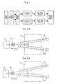
- Fig.1 is an architecture diagram of a binocular steroscopic scanning radiographic imaging system according to the present invention.
- the binocular steroscopic scanning radiographic imaging system of the present invention comprises the following devices:
- the radiation source 1, cooperating with the beam controller 2 emits two X-ray beams, which are symmetric or asymmetric and have an angle between them.
- the X-ray beams after penetrating through an object under detection 3, are received by the left detector array 4 and the right detector array 5, respectively, and then converted into electric signals to be inputted to the left and right image acquisition systems 6 and 7, respectively.
- the image data from the left and right image acquisition systems 6 and 7 can be used to display each of the detected objection images or the tomograms of different depth reconstructed from the two images on a computer display.
- One preferred embodiment of the present invention uses a double-slit collimator as the beam controller for beam control on the rays emitted by the radiation source.
- Figs.2 and 3 are top and side views for schematic layout of the devices needed for implementing the present invention, respectively, where Fig.2A depicts the case of symmetric ray beams, and Fig.2B depicts the case of asymmetric ray beams.
- two collimation slits are provided in the beam controller to shape the X-rays emitted by the radiation source into two ray beams, either symmetric or asymmetric, with an angle between them.
- Both of the left detector arrays 4 and 5 face directly the beam sector defined by the collimation slits of the double-slit collimator, scan and examine the object under detection in a symmetric fashion and transmit the electric signals to the corresponding left and right image acquisition systems.
- the computer processing system 8 carries out image processing to obtain the transmission tomograms containing depth information.
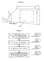
- Fig.4 is a flowchart for the operation of a binocular steroscopic scanning radiographic imaging method according to the present invention.
- the specific operation process of the binocular steroscopic scanning radiographic imaging method according to the present invention will be elaborated with reference to Fig.4 .
- one radiation source emits two beams of rays in order to create two transmission images, i.e., left and right ones.
- X-rays emitted by the same radiation source are used.
- the X-rays after passing through a double-slit collimator, form two beams and penetrate through the object under detection, where the two beams have an angle between them and define a beam sector.
- the left beam in the beam sector is received by a left detector array and then converted into electric signals to be inputted to a left image acquisition module for generating a left view
- the right beam in the beam sector is received by a right detector array and then converted into electric signals to be inputted to a right image acquisition module for generating a right view.
- the left and right views are formed by passing the X-rays emitted by the single radiation source through the double-slit collimator to generate two beams angled from each other and making the two beams penetrate through the object under detection in a beam sector fashion, respectively, the radiation source for the left and right views is the same and thus consistent in characteristics, and there is certain parallax between the left and right views.
- the value of the parallax depends on the angle between the two beams as well as the spatial position of the object under detection along the depth direction.
- the left and right views are segmented in step 402. Such image segmentation is necessary for the left and right views in order to obtain the tomograms of the transmission views along the depth direction and thus remove the effect of image superimposition.
- the edge extraction algorithm is applied to image segmentation.
- the edge extraction method is one of typical discontinuous segmentation methods. In this method, several edges are firstly obtained by detecting local discontinuity and then connected with each other. This edge extraction method is reliable in the segmentation of an X-ray transmission image due to the inherent characteristics of the X-ray transmission image for overlapping objects.
- Sobel and Canny edge detection operators are used simultaneously to extract edges, which are then synthesized into a resultant edge image. Finally, edge connection is performed on the resultant edge image so as to define enclosed regions. In this way, the segmentation for each of the left and right views can be completed.
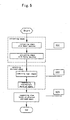
- Fig.5 is a flowchart for image segmentation according to the present invention. The specific operation process of the image segmentation according to the present invention will be elaborated with reference to Fig.5 .
- Sobel and Canny edge detection operators are used simultaneously for edge extraction.
- the convolution operators are expressed as 1 2 1 0 0 0 - 1 - 2 - 1 ⁇ x ⁇ f , 1 0 - 1 2 0 - 2 1 0 - 1 . ⁇ y ⁇ f
- a threshold Th is selected, and any pixel (i, j) will be determined as a step-type edge point if it fulfills the inequation S ( i,j )> Th , where S(i, j) represents the resultant edge image.
- Canny edge detection algorithm generally comprises steps of: smoothing the image with a Gauss filter; calculating the magnitude and direction of gradient by use of finite difference of one-order partial derivative; applying non-maximum suppression image to the magnitude of gradient; and detecting and connecting edges via a double threshold algorithm.
- Canny operator can reduce pseudo edges by using the double threshold algorithm.
- the non-maximum suppression image is binarized with two thresholds Th 1 and Th 2 , where 2 Th 1 ⁇ Th 2 , to obtain two threshold edge images N 1 ( i,j ) and N 2 ( i,j ) .
- N 2 ( i,j ) is extracted with the higher threshold Th 2 and thus has fewer pseudo edges, but there is discontinuity in it.
- each intermittent edge into an integral and continuous one in N 2 ( i,j ) .
- the algorithm begins with a pixel referred to as an end point in N 2 ( i,j ), then searches at 8-neighborhood around a pixel in N 1 ( i,j ) corresponding to the end point for a pixel which can be connected with the end point. In this way, the algorithm continuously and repeatedly collects edge points in N 1 ( i, j ) until the intermittent edge in N 2 ( i, j ) is rendered into an uninterrupted outline.
- an enclosed edge image is obtained in step 502. As will be explained later, all of the edges detected by Sobel and Canny edge detection operators should be taken into account to enable edge connection for a satisfactory closed edge image.
- the initial edge image results from a logic OR operation between the binary edge images by the above two operators.
- Each of the edges obtained by the foregoing method usually comprises intermittent parts or even individual edge pixels due to the effect of noise and the like, it is therefore necessary to connect these parts or edge pixels.
- two edge pixels are connected based on the similarity of them in terms of gradient magnitude and/or gradient direction.
- a pixel (s, t) can be connected with a pixel (x, y) if the former lies in the neighborhood of the latter, and their gradient magnitudes and gradient directions meet the following requirement with respect to the given thresholds:
- ⁇ f x ⁇ y G x
- y ⁇ f / ⁇ x ⁇ f / ⁇ y
- T represents the threshold for magnitude
- A is the one for angle.
- each image of the left and right views is segmented according to a corresponding resultant enclosed edge image.
- the image is partitioned into two kinds of regions, i.e., inner and outer, by the closed edge, morphological dilation-erosion operation can be employed to find a pixel belonging to one of the inner regions.
- the pixels belonging to the inner region are filled with the value of "1"
- the pixels belonging to the outer region are filled with the value of "0”.
- the binary template for each inner region is obtained, and the image segmentation is then completed.
- the above flow starts with searching for edges in the original image with both of Sobel and Canny operators to obtain two edge images. Then, the two edge images are combined into one, and the broken parts or points are connected. The object template is finally extracted by assigning "1" to the regions within the closed edges and "0" to the regions outside.
- the segmentation results of the left and right views are matched in step 403.
- the matching is conducted based on the geometric features of the left and right segmentation results.
- the set of object properties ⁇ P k ⁇ is allocated with corresponding weights ⁇ W k ⁇ .
- the set of object properties for the left view is ⁇ P i,k ⁇
- the set of object properties for the left (right) view is ⁇ P j,k ⁇
- i and j serve as object indexes in the left and right views, respectively
- a threshold Th mat is selected in such a manner that, when E i,j reaches its minimum and E i,j ⁇ Th mat holds, the corresponding i and j designate the matched objects in the left and right views, that is, i and j are the indexes for the segmentation results.
- the matching result in the above example is (a) being matched with (b), (c) with (d) and (e) with (f).
- step 404 the tomograms of the transmission image are constructed in the depth direction, and the grey level of each tomogram is reconstructed.
- the shape tomograms of the transmission image can be reconstructed in the depth direction, and the grey level for each tomogram can also be reconstructed. In this way, the objects overlaying on each other are classified into different tomograms, thereby eliminating the effect of superimposition in the transmission image.
- Fig.8 shows a detailed flowchart for grey level reconstruction according to the present invention.
- the concrete implementation process according to the present invention will be elaborated with reference to Fig.8 .
- the grey level for each object is reconstructed by peeling off the grey level layer by layer from the outermost to the innermost.
- the grey level for the matched object on the outermost lay (directly adjacent to the background region) is first reconstructed and peeled off from the image. Then, the object on the next outermost lay is processed in the same way. This procedure is repeated until the grey level reconstruction has been performed on all the matched objects.
- the specific steps are:
- the steps 802 to 805 are repeated until the grey level reconstruction has been performed on all the matched objects.
- each of the objects comprises only two types of parts, one being the part adjacent to the background region, the other being the part overlaid by another object.
- some of the region where the overlaying object lies must turn into part of the background region and thus can be treated as a new background region after a sufficient number of peeling off, and therefore the overlaid object will has an edge adjacent to the new background region.
- Fig.6 is a diagram showing the effect after segmenting left and right views of three-layer superimposition according to the present invention.
- (a) represents the left view
- (b) represents the right view.
- the effect after segmenting the left and right views is: (c) for the template of the first object in the left view and (d) for the template of the first object in the right view, with the pair of object templates being two larger rectangles as shown in the figure; (e) for the template of the second object in the left view and (f) for the template of the second object in the right view, with the pair of object templates being two smaller rectangles as shown in the figure; and (g) for the template of the third object in the left view and (h) for the template of the third object in the right view, with the pair of object templates being two ellipses as shown in the figure.
- Fig.7 is a schematic diagram for binocular steroscopic tomograms of the transmission image in the depth direction according to the present invention.
- a spatially orthogonal coordinates is established such that the scanning direction (vertically upward) is denoted by the positive direction of x axis, the alignment direction of the detector array (outward vertically to the plane of the figure) is denoted by the positive direction of y axis, the horizontally rightward direction is denoted by the positive direction of z axis, and the location O of the radiation source S is taken as the origin of the coordinates.
- the tomograms are a series of spatial planes parallel to the x-O-y plane, and what is shown by the broken line in the figure denotes the projection of the tomogram planes in the x-O-z plane.
- L represents the projection of left primary beam in the x-O-z plane
- R represents the projection of right primary beam in the x-O-z plane
- ⁇ is the angle between the projection of the left and right ray beam in the x-O-z plane.
- the parallax is directly proportional to the tomogram depth. This can be proven as shown in Fig.7 , in which the object denoted by (a) and (b) lies on the first layer and thus has a minimum depth since its parallax is the smallest; the object denoted by (c) and (d) lies on the second layer and thus has a medium depth since its parallax is in the middle; and the object denoted by (e) and (f) lies on the third layer and thus has a maximum depth since its parallax is the greatest.
Landscapes
- Life Sciences & Earth Sciences (AREA)
- Physics & Mathematics (AREA)
- Health & Medical Sciences (AREA)
- Engineering & Computer Science (AREA)
- General Physics & Mathematics (AREA)
- Pathology (AREA)
- Medical Informatics (AREA)
- High Energy & Nuclear Physics (AREA)
- General Health & Medical Sciences (AREA)
- Nuclear Medicine, Radiotherapy & Molecular Imaging (AREA)
- Surgery (AREA)
- Biophysics (AREA)
- Biochemistry (AREA)
- Analytical Chemistry (AREA)
- Chemical & Material Sciences (AREA)
- Optics & Photonics (AREA)
- Radiology & Medical Imaging (AREA)
- Biomedical Technology (AREA)
- Heart & Thoracic Surgery (AREA)
- Molecular Biology (AREA)
- Immunology (AREA)
- Animal Behavior & Ethology (AREA)
- Public Health (AREA)
- Veterinary Medicine (AREA)
- Computer Vision & Pattern Recognition (AREA)
- Theoretical Computer Science (AREA)
- General Life Sciences & Earth Sciences (AREA)
- Geophysics (AREA)
- Analysing Materials By The Use Of Radiation (AREA)
- Image Processing (AREA)
- Apparatus For Radiation Diagnosis (AREA)
Priority Applications (1)
| Application Number | Priority Date | Filing Date | Title |
|---|---|---|---|
| PL07119938T PL1938752T3 (pl) | 2006-12-28 | 2007-11-04 | Sposób oraz system obrazowania radiograficznego przez dwuoczne stereoskopowe skanowanie |
Applications Claiming Priority (2)
| Application Number | Priority Date | Filing Date | Title |
|---|---|---|---|
| CN200610169800 | 2006-12-28 | ||
| CN2007101301379A CN101210895B (zh) | 2006-12-28 | 2007-07-20 | 一种双视角扫描辐射成像的方法及系统 |
Publications (2)
| Publication Number | Publication Date |
|---|---|
| EP1938752A1 EP1938752A1 (en) | 2008-07-02 |
| EP1938752B1 true EP1938752B1 (en) | 2010-08-04 |
Family
ID=39588126
Family Applications (1)
| Application Number | Title | Priority Date | Filing Date |
|---|---|---|---|
| EP07119938A Active EP1938752B1 (en) | 2006-12-28 | 2007-11-04 | Method and system for binocular steroscopic scanning radiographic imaging |
Country Status (9)
| Country | Link |
|---|---|
| US (1) | US7545906B2 (pl) |
| EP (1) | EP1938752B1 (pl) |
| CN (1) | CN101210895B (pl) |
| AT (1) | ATE476142T1 (pl) |
| BR (1) | BRPI0719616B1 (pl) |
| DE (1) | DE602007008193D1 (pl) |
| PL (1) | PL1938752T3 (pl) |
| TR (1) | TR200904838T1 (pl) |
| WO (1) | WO2008080281A1 (pl) |
Families Citing this family (28)
| Publication number | Priority date | Publication date | Assignee | Title |
|---|---|---|---|---|
| CN101358936B (zh) | 2007-08-02 | 2011-03-16 | 同方威视技术股份有限公司 | 一种利用双视角多能量透射图像进行材料识别的方法及系统 |
| FR2919780B1 (fr) * | 2007-08-02 | 2017-09-08 | Nuctech Co Ltd | Procede et systeme d'identification de matiere a l'aide d'images binoculaires stereoscopiques et par transmission multi-energie |
| TW200937344A (en) * | 2008-02-20 | 2009-09-01 | Ind Tech Res Inst | Parallel processing method for synthesizing an image with multi-view images |
| TWI346595B (en) * | 2009-01-13 | 2011-08-11 | Univ Chung Yuan Christian | System for positioning micro tool of micro machine and method thereof |
| CN101702056B (zh) * | 2009-11-25 | 2011-07-20 | 中航华东光电有限公司 | 基于立体图像对的立体图像显示方法 |
| CN101953694B (zh) * | 2010-09-03 | 2012-07-25 | 北京睿思厚德辐射信息科技有限公司 | 医用和工业用x射线实时立体成像装置 |
| CN101943761B (zh) * | 2010-09-12 | 2012-09-05 | 上海英迈吉东影图像设备有限公司 | 一种x射线检测方法 |
| JP5506726B2 (ja) * | 2011-03-28 | 2014-05-28 | 富士フイルム株式会社 | 放射線画像撮影方法、並びに、放射線検出器および放射線画像撮影装置 |
| CN102253064A (zh) * | 2011-03-30 | 2011-11-23 | 上海高晶金属探测设备有限公司 | X射线检测装置 |
| CN102609917B (zh) * | 2012-02-13 | 2014-01-08 | 江苏博智软件科技有限公司 | 一种基于聚类算法的图像边缘拟合b样条生成方法 |
| CN103226114B (zh) * | 2013-04-02 | 2015-09-30 | 清华大学 | 多视角立体辐射成像系统及方法 |
| CN104567758B (zh) * | 2013-10-29 | 2017-11-17 | 同方威视技术股份有限公司 | 立体成像系统及其方法 |
| CN104754848B (zh) * | 2013-12-30 | 2017-12-08 | 同方威视技术股份有限公司 | X射线发生装置以及具有该装置的x射线透视成像系统 |
| CN104749198B (zh) | 2013-12-30 | 2019-08-06 | 同方威视技术股份有限公司 | 双通道高能x射线透视成像系统 |
| CN104749199B (zh) | 2013-12-30 | 2019-02-19 | 同方威视技术股份有限公司 | 双能/双视角的高能x射线透视成像系统 |
| JP6214457B2 (ja) * | 2014-04-18 | 2017-10-18 | キヤノン株式会社 | 画像処理方法、画像処理装置、撮像装置、画像処理プログラム、および、記憶媒体 |
| CN104407746A (zh) * | 2014-12-01 | 2015-03-11 | 湖北印象光电信息产业有限公司 | 一种基于红外光电技术的多点触摸系统 |
| CN106443806B (zh) * | 2016-09-18 | 2020-01-14 | 北京君和信达科技有限公司 | 辐射成像系统和图像处理方法 |
| CN108460800B (zh) * | 2016-12-12 | 2020-10-09 | 交通运输部水运科学研究所 | 集装箱图像定位方法及系统 |
| CN108240997B (zh) * | 2016-12-26 | 2020-09-04 | 同方威视技术股份有限公司 | 检查设备和对集装箱进行检查的方法 |
| CN107037494B (zh) * | 2017-04-07 | 2019-08-06 | 北京华力兴科技发展有限责任公司 | 控制方法及控制装置、车辆或集装箱的安检系统 |
| CN108508043A (zh) * | 2018-06-06 | 2018-09-07 | 南京正驰科技发展有限公司 | 单源双视角安检机 |
| CN109459023B (zh) * | 2018-09-18 | 2021-07-16 | 武汉三体机器人有限公司 | 一种基于无人机视觉slam的辅助地面机器人导航方法及装置 |
| CN109902643B (zh) * | 2019-03-07 | 2021-03-16 | 浙江啄云智能科技有限公司 | 基于深度学习的智能安检方法、装置、系统及其电子设备 |
| CN110147792B (zh) * | 2019-05-22 | 2021-05-28 | 齐鲁工业大学 | 基于内存优化的药品包装字符高速检测系统及方法 |
| CN114052642A (zh) * | 2021-11-19 | 2022-02-18 | 付强 | 一种裸眼3d脊柱显微内镜系统 |
| CN114897750B (zh) * | 2022-04-02 | 2025-08-29 | 首都医科大学附属北京儿童医院 | 基于Sobel算子的腭中缝图像重构方法及系统 |
| CN116371755A (zh) * | 2023-04-04 | 2023-07-04 | 牧原肉食品有限公司 | 一种胴体异物检测系统及检测方法 |
Family Cites Families (10)
| Publication number | Priority date | Publication date | Assignee | Title |
|---|---|---|---|---|
| US3693095A (en) * | 1970-10-28 | 1972-09-19 | Sperry Rand Corp | Radiometer gain control reference |
| GB8623196D0 (en) * | 1986-09-26 | 1986-10-29 | Robinson M | Visual screening system |
| GB9302271D0 (en) * | 1993-02-05 | 1993-03-24 | Robinson Max | The visual presentation of information derived for a 3d image system |
| US5583904A (en) * | 1995-04-11 | 1996-12-10 | Hewlett-Packard Co. | Continuous linear scan laminography system and method |
| AU1060899A (en) * | 1997-09-09 | 1999-03-29 | American Science And Engineering Inc. | A tomographic inspection system |
| US6701005B1 (en) * | 2000-04-29 | 2004-03-02 | Cognex Corporation | Method and apparatus for three-dimensional object segmentation |
| CN1144039C (zh) * | 2000-09-21 | 2004-03-31 | 清华大学 | 单辐射源双成像扫描辐射成像方法及其装置 |
| US6904122B2 (en) * | 2001-10-31 | 2005-06-07 | Inventqjaya Sdn. Bhd. | 3D stereoscopic X-ray system |
| GB2390005A (en) | 2002-06-17 | 2003-12-24 | Royal Holloway University Of L | Screening Apparatus |
| US7283901B2 (en) * | 2005-01-13 | 2007-10-16 | Trw Automotive U.S. Llc | Controller system for a vehicle occupant protection device |
-
2007
- 2007-07-20 TR TR2009/04838T patent/TR200904838T1/xx unknown
- 2007-07-20 WO PCT/CN2007/002215 patent/WO2008080281A1/zh not_active Ceased
- 2007-07-20 CN CN2007101301379A patent/CN101210895B/zh active Active
- 2007-07-20 BR BRPI0719616-4A patent/BRPI0719616B1/pt not_active IP Right Cessation
- 2007-11-04 AT AT07119938T patent/ATE476142T1/de active
- 2007-11-04 EP EP07119938A patent/EP1938752B1/en active Active
- 2007-11-04 DE DE602007008193T patent/DE602007008193D1/de active Active
- 2007-11-04 PL PL07119938T patent/PL1938752T3/pl unknown
- 2007-12-13 US US11/955,863 patent/US7545906B2/en active Active
Also Published As
| Publication number | Publication date |
|---|---|
| BRPI0719616B1 (pt) | 2019-07-16 |
| WO2008080281A1 (en) | 2008-07-10 |
| PL1938752T3 (pl) | 2010-12-31 |
| CN101210895A (zh) | 2008-07-02 |
| TR200904838T1 (tr) | 2009-10-21 |
| DE602007008193D1 (de) | 2010-09-16 |
| US7545906B2 (en) | 2009-06-09 |
| EP1938752A1 (en) | 2008-07-02 |
| BRPI0719616A8 (pt) | 2019-01-22 |
| BRPI0719616A2 (pt) | 2013-12-10 |
| US20080205590A1 (en) | 2008-08-28 |
| ATE476142T1 (de) | 2010-08-15 |
| CN101210895B (zh) | 2011-09-28 |
Similar Documents
| Publication | Publication Date | Title |
|---|---|---|
| US7545906B2 (en) | Method and system for binocular steroscopic scanning radiographic imaging | |
| US8194953B2 (en) | Method and system of material identification using binocular steroscopic and multi-energy transmission images | |
| EP2869094B1 (en) | Stereoscopic imaging systems and methods | |
| US8582857B2 (en) | Dual-energy material identification method and apparatus with undersampling | |
| US20130231559A1 (en) | System and method for providing 2-dimensional computerized- tomography image corresponding to 2-dimensional ultrasound image | |
| US20080193006A1 (en) | User-Steered 3D Image Segmentation Methods | |
| JP2008043758A (ja) | オパシティの検出のために放射線画像を処理するための方法 | |
| JP2007268273A (ja) | 骨または他のカルシウム含有物質と軟部組織内の造影剤との自動差別化方法および装置 | |
| JP2005334317A (ja) | 超音波診断装置及び画像処理方法 | |
| JP2005530153A (ja) | 三次元座標を取得するための立体x線撮像装置 | |
| CN101422373B (zh) | 一种实现ct图像的感兴趣区域与ct定位片的融合方法 | |
| HK1245975B (zh) | 通过3-d成像对场景中的对象进行区分和識别的方法 | |
| US6278760B1 (en) | Radiation image forming method and apparatus | |
| CN114004765A (zh) | 一种安检设备中dr透视图像的畸变校正方法及装置 | |
| EP4352689B1 (en) | Organ segmentation in image | |
| JP2006325629A (ja) | 3次元関心領域設定方法,画像取得装置およびプログラム | |
| JP5491237B2 (ja) | 医用画像表示装置及び医用画像表示方法 | |
| US20240221111A1 (en) | Stitching multiple images to create a panoramic image | |
| GB2454047A (en) | Method and system of material identification using binocular stereoscopic and multi-energy transmission images | |
| HK1129454A (en) | Method and system of material identification using binocular stereoscopic and multi-energy transmission images |
Legal Events
| Date | Code | Title | Description |
|---|---|---|---|
| PUAI | Public reference made under article 153(3) epc to a published international application that has entered the european phase |
Free format text: ORIGINAL CODE: 0009012 |
|
| 17P | Request for examination filed |
Effective date: 20080507 |
|
| AK | Designated contracting states |
Kind code of ref document: A1 Designated state(s): AT BE BG CH CY CZ DE DK EE ES FI FR GB GR HU IE IS IT LI LT LU LV MC MT NL PL PT RO SE SI SK TR |
|
| AX | Request for extension of the european patent |
Extension state: AL BA HR MK RS |
|
| 17Q | First examination report despatched |
Effective date: 20080811 |
|
| AKX | Designation fees paid |
Designated state(s): AT BE BG CH CY CZ DE DK EE ES FI FR GB GR HU IE IS IT LI LT LU LV MC MT NL PL PT RO SE SI SK TR |
|
| GRAP | Despatch of communication of intention to grant a patent |
Free format text: ORIGINAL CODE: EPIDOSNIGR1 |
|
| GRAS | Grant fee paid |
Free format text: ORIGINAL CODE: EPIDOSNIGR3 |
|
| GRAA | (expected) grant |
Free format text: ORIGINAL CODE: 0009210 |
|
| AK | Designated contracting states |
Kind code of ref document: B1 Designated state(s): AT BE BG CH CY CZ DE DK EE ES FI FR GB GR HU IE IS IT LI LT LU LV MC MT NL PL PT RO SE SI SK TR |
|
| REG | Reference to a national code |
Ref country code: GB Ref legal event code: FG4D |
|
| REG | Reference to a national code |
Ref country code: CH Ref legal event code: EP |
|
| REG | Reference to a national code |
Ref country code: IE Ref legal event code: FG4D |
|
| REF | Corresponds to: |
Ref document number: 602007008193 Country of ref document: DE Date of ref document: 20100916 Kind code of ref document: P |
|
| REG | Reference to a national code |
Ref country code: RO Ref legal event code: EPE |
|
| REG | Reference to a national code |
Ref country code: NL Ref legal event code: VDEP Effective date: 20100804 |
|
| LTIE | Lt: invalidation of european patent or patent extension |
Effective date: 20100804 |
|
| PG25 | Lapsed in a contracting state [announced via postgrant information from national office to epo] |
Ref country code: FI Free format text: LAPSE BECAUSE OF FAILURE TO SUBMIT A TRANSLATION OF THE DESCRIPTION OR TO PAY THE FEE WITHIN THE PRESCRIBED TIME-LIMIT Effective date: 20100804 Ref country code: NL Free format text: LAPSE BECAUSE OF FAILURE TO SUBMIT A TRANSLATION OF THE DESCRIPTION OR TO PAY THE FEE WITHIN THE PRESCRIBED TIME-LIMIT Effective date: 20100804 Ref country code: LT Free format text: LAPSE BECAUSE OF FAILURE TO SUBMIT A TRANSLATION OF THE DESCRIPTION OR TO PAY THE FEE WITHIN THE PRESCRIBED TIME-LIMIT Effective date: 20100804 |
|
| PG25 | Lapsed in a contracting state [announced via postgrant information from national office to epo] |
Ref country code: SI Free format text: LAPSE BECAUSE OF FAILURE TO SUBMIT A TRANSLATION OF THE DESCRIPTION OR TO PAY THE FEE WITHIN THE PRESCRIBED TIME-LIMIT Effective date: 20100804 Ref country code: BG Free format text: LAPSE BECAUSE OF FAILURE TO SUBMIT A TRANSLATION OF THE DESCRIPTION OR TO PAY THE FEE WITHIN THE PRESCRIBED TIME-LIMIT Effective date: 20101104 Ref country code: CY Free format text: LAPSE BECAUSE OF FAILURE TO SUBMIT A TRANSLATION OF THE DESCRIPTION OR TO PAY THE FEE WITHIN THE PRESCRIBED TIME-LIMIT Effective date: 20100804 Ref country code: IS Free format text: LAPSE BECAUSE OF FAILURE TO SUBMIT A TRANSLATION OF THE DESCRIPTION OR TO PAY THE FEE WITHIN THE PRESCRIBED TIME-LIMIT Effective date: 20101204 Ref country code: PT Free format text: LAPSE BECAUSE OF FAILURE TO SUBMIT A TRANSLATION OF THE DESCRIPTION OR TO PAY THE FEE WITHIN THE PRESCRIBED TIME-LIMIT Effective date: 20101206 |
|
| REG | Reference to a national code |
Ref country code: HU Ref legal event code: AG4A Ref document number: E009114 Country of ref document: HU |
|
| PG25 | Lapsed in a contracting state [announced via postgrant information from national office to epo] |
Ref country code: BE Free format text: LAPSE BECAUSE OF FAILURE TO SUBMIT A TRANSLATION OF THE DESCRIPTION OR TO PAY THE FEE WITHIN THE PRESCRIBED TIME-LIMIT Effective date: 20100804 Ref country code: SE Free format text: LAPSE BECAUSE OF FAILURE TO SUBMIT A TRANSLATION OF THE DESCRIPTION OR TO PAY THE FEE WITHIN THE PRESCRIBED TIME-LIMIT Effective date: 20100804 Ref country code: GR Free format text: LAPSE BECAUSE OF FAILURE TO SUBMIT A TRANSLATION OF THE DESCRIPTION OR TO PAY THE FEE WITHIN THE PRESCRIBED TIME-LIMIT Effective date: 20101105 Ref country code: LV Free format text: LAPSE BECAUSE OF FAILURE TO SUBMIT A TRANSLATION OF THE DESCRIPTION OR TO PAY THE FEE WITHIN THE PRESCRIBED TIME-LIMIT Effective date: 20100804 |
|
| PG25 | Lapsed in a contracting state [announced via postgrant information from national office to epo] |
Ref country code: DK Free format text: LAPSE BECAUSE OF FAILURE TO SUBMIT A TRANSLATION OF THE DESCRIPTION OR TO PAY THE FEE WITHIN THE PRESCRIBED TIME-LIMIT Effective date: 20100804 |
|
| PG25 | Lapsed in a contracting state [announced via postgrant information from national office to epo] |
Ref country code: EE Free format text: LAPSE BECAUSE OF FAILURE TO SUBMIT A TRANSLATION OF THE DESCRIPTION OR TO PAY THE FEE WITHIN THE PRESCRIBED TIME-LIMIT Effective date: 20100804 Ref country code: CZ Free format text: LAPSE BECAUSE OF FAILURE TO SUBMIT A TRANSLATION OF THE DESCRIPTION OR TO PAY THE FEE WITHIN THE PRESCRIBED TIME-LIMIT Effective date: 20100804 Ref country code: SK Free format text: LAPSE BECAUSE OF FAILURE TO SUBMIT A TRANSLATION OF THE DESCRIPTION OR TO PAY THE FEE WITHIN THE PRESCRIBED TIME-LIMIT Effective date: 20100804 |
|
| PLBE | No opposition filed within time limit |
Free format text: ORIGINAL CODE: 0009261 |
|
| STAA | Information on the status of an ep patent application or granted ep patent |
Free format text: STATUS: NO OPPOSITION FILED WITHIN TIME LIMIT |
|
| PG25 | Lapsed in a contracting state [announced via postgrant information from national office to epo] |
Ref country code: ES Free format text: LAPSE BECAUSE OF FAILURE TO SUBMIT A TRANSLATION OF THE DESCRIPTION OR TO PAY THE FEE WITHIN THE PRESCRIBED TIME-LIMIT Effective date: 20101115 Ref country code: MC Free format text: LAPSE BECAUSE OF NON-PAYMENT OF DUE FEES Effective date: 20101130 |
|
| 26N | No opposition filed |
Effective date: 20110506 |
|
| REG | Reference to a national code |
Ref country code: DE Ref legal event code: R097 Ref document number: 602007008193 Country of ref document: DE Effective date: 20110506 |
|
| PG25 | Lapsed in a contracting state [announced via postgrant information from national office to epo] |
Ref country code: IE Free format text: LAPSE BECAUSE OF NON-PAYMENT OF DUE FEES Effective date: 20101104 |
|
| PG25 | Lapsed in a contracting state [announced via postgrant information from national office to epo] |
Ref country code: IT Free format text: LAPSE BECAUSE OF NON-PAYMENT OF DUE FEES Effective date: 20101104 Ref country code: MT Free format text: LAPSE BECAUSE OF FAILURE TO SUBMIT A TRANSLATION OF THE DESCRIPTION OR TO PAY THE FEE WITHIN THE PRESCRIBED TIME-LIMIT Effective date: 20100804 |
|
| REG | Reference to a national code |
Ref country code: CH Ref legal event code: PL |
|
| PG25 | Lapsed in a contracting state [announced via postgrant information from national office to epo] |
Ref country code: CH Free format text: LAPSE BECAUSE OF NON-PAYMENT OF DUE FEES Effective date: 20111130 Ref country code: LI Free format text: LAPSE BECAUSE OF NON-PAYMENT OF DUE FEES Effective date: 20111130 |
|
| PG25 | Lapsed in a contracting state [announced via postgrant information from national office to epo] |
Ref country code: LU Free format text: LAPSE BECAUSE OF NON-PAYMENT OF DUE FEES Effective date: 20101104 |
|
| REG | Reference to a national code |
Ref country code: FR Ref legal event code: PLFP Year of fee payment: 9 |
|
| REG | Reference to a national code |
Ref country code: FR Ref legal event code: PLFP Year of fee payment: 10 |
|
| REG | Reference to a national code |
Ref country code: FR Ref legal event code: PLFP Year of fee payment: 11 |
|
| PGFP | Annual fee paid to national office [announced via postgrant information from national office to epo] |
Ref country code: HU Payment date: 20191121 Year of fee payment: 13 Ref country code: RO Payment date: 20191024 Year of fee payment: 13 Ref country code: DE Payment date: 20191029 Year of fee payment: 13 |
|
| PGFP | Annual fee paid to national office [announced via postgrant information from national office to epo] |
Ref country code: IT Payment date: 20191108 Year of fee payment: 13 Ref country code: PL Payment date: 20191029 Year of fee payment: 13 Ref country code: FR Payment date: 20191113 Year of fee payment: 13 |
|
| PGFP | Annual fee paid to national office [announced via postgrant information from national office to epo] |
Ref country code: AT Payment date: 20191025 Year of fee payment: 13 Ref country code: TR Payment date: 20191028 Year of fee payment: 13 |
|
| REG | Reference to a national code |
Ref country code: DE Ref legal event code: R119 Ref document number: 602007008193 Country of ref document: DE |
|
| REG | Reference to a national code |
Ref country code: AT Ref legal event code: MM01 Ref document number: 476142 Country of ref document: AT Kind code of ref document: T Effective date: 20201104 |
|
| PG25 | Lapsed in a contracting state [announced via postgrant information from national office to epo] |
Ref country code: RO Free format text: LAPSE BECAUSE OF NON-PAYMENT OF DUE FEES Effective date: 20201104 |
|
| PG25 | Lapsed in a contracting state [announced via postgrant information from national office to epo] |
Ref country code: HU Free format text: LAPSE BECAUSE OF NON-PAYMENT OF DUE FEES Effective date: 20201105 Ref country code: AT Free format text: LAPSE BECAUSE OF NON-PAYMENT OF DUE FEES Effective date: 20201104 |
|
| PG25 | Lapsed in a contracting state [announced via postgrant information from national office to epo] |
Ref country code: IT Free format text: LAPSE BECAUSE OF NON-PAYMENT OF DUE FEES Effective date: 20201104 Ref country code: FR Free format text: LAPSE BECAUSE OF NON-PAYMENT OF DUE FEES Effective date: 20201130 |
|
| PG25 | Lapsed in a contracting state [announced via postgrant information from national office to epo] |
Ref country code: DE Free format text: LAPSE BECAUSE OF NON-PAYMENT OF DUE FEES Effective date: 20210601 |
|
| PG25 | Lapsed in a contracting state [announced via postgrant information from national office to epo] |
Ref country code: TR Free format text: LAPSE BECAUSE OF NON-PAYMENT OF DUE FEES Effective date: 20201104 |
|
| PG25 | Lapsed in a contracting state [announced via postgrant information from national office to epo] |
Ref country code: PL Free format text: LAPSE BECAUSE OF NON-PAYMENT OF DUE FEES Effective date: 20201104 |
|
| P01 | Opt-out of the competence of the unified patent court (upc) registered |
Effective date: 20230526 |
|
| PGFP | Annual fee paid to national office [announced via postgrant information from national office to epo] |
Ref country code: GB Payment date: 20240904 Year of fee payment: 18 |