EP1938473B1 - Network-controlled feedback for mimo systems - Google Patents
Network-controlled feedback for mimo systems Download PDFInfo
- Publication number
- EP1938473B1 EP1938473B1 EP06799839.3A EP06799839A EP1938473B1 EP 1938473 B1 EP1938473 B1 EP 1938473B1 EP 06799839 A EP06799839 A EP 06799839A EP 1938473 B1 EP1938473 B1 EP 1938473B1
- Authority
- EP
- European Patent Office
- Prior art keywords
- downlink transmission
- channel quality
- performance metric
- mode
- feedback
- Prior art date
- Legal status (The legal status is an assumption and is not a legal conclusion. Google has not performed a legal analysis and makes no representation as to the accuracy of the status listed.)
- Active
Links
Images
Classifications
-
- H—ELECTRICITY
- H04—ELECTRIC COMMUNICATION TECHNIQUE
- H04B—TRANSMISSION
- H04B7/00—Radio transmission systems, i.e. using radiation field
- H04B7/02—Diversity systems; Multi-antenna system, i.e. transmission or reception using multiple antennas
- H04B7/04—Diversity systems; Multi-antenna system, i.e. transmission or reception using multiple antennas using two or more spaced independent antennas
- H04B7/06—Diversity systems; Multi-antenna system, i.e. transmission or reception using multiple antennas using two or more spaced independent antennas at the transmitting station
- H04B7/0613—Diversity systems; Multi-antenna system, i.e. transmission or reception using multiple antennas using two or more spaced independent antennas at the transmitting station using simultaneous transmission
- H04B7/0615—Diversity systems; Multi-antenna system, i.e. transmission or reception using multiple antennas using two or more spaced independent antennas at the transmitting station using simultaneous transmission of weighted versions of same signal
- H04B7/0619—Diversity systems; Multi-antenna system, i.e. transmission or reception using multiple antennas using two or more spaced independent antennas at the transmitting station using simultaneous transmission of weighted versions of same signal using feedback from receiving side
- H04B7/0636—Feedback format
- H04B7/0645—Variable feedback
-
- H—ELECTRICITY
- H04—ELECTRIC COMMUNICATION TECHNIQUE
- H04B—TRANSMISSION
- H04B1/00—Details of transmission systems, not covered by a single one of groups H04B3/00 - H04B13/00; Details of transmission systems not characterised by the medium used for transmission
- H04B1/69—Spread spectrum techniques
- H04B1/707—Spread spectrum techniques using direct sequence modulation
- H04B1/7097—Interference-related aspects
- H04B1/7103—Interference-related aspects the interference being multiple access interference
- H04B1/7107—Subtractive interference cancellation
- H04B1/71072—Successive interference cancellation
-
- H—ELECTRICITY
- H04—ELECTRIC COMMUNICATION TECHNIQUE
- H04B—TRANSMISSION
- H04B7/00—Radio transmission systems, i.e. using radiation field
- H04B7/02—Diversity systems; Multi-antenna system, i.e. transmission or reception using multiple antennas
- H04B7/04—Diversity systems; Multi-antenna system, i.e. transmission or reception using multiple antennas using two or more spaced independent antennas
- H04B7/06—Diversity systems; Multi-antenna system, i.e. transmission or reception using multiple antennas using two or more spaced independent antennas at the transmitting station
- H04B7/0613—Diversity systems; Multi-antenna system, i.e. transmission or reception using multiple antennas using two or more spaced independent antennas at the transmitting station using simultaneous transmission
- H04B7/0615—Diversity systems; Multi-antenna system, i.e. transmission or reception using multiple antennas using two or more spaced independent antennas at the transmitting station using simultaneous transmission of weighted versions of same signal
- H04B7/0619—Diversity systems; Multi-antenna system, i.e. transmission or reception using multiple antennas using two or more spaced independent antennas at the transmitting station using simultaneous transmission of weighted versions of same signal using feedback from receiving side
- H04B7/0621—Feedback content
- H04B7/0632—Channel quality parameters, e.g. channel quality indicator [CQI]
-
- H—ELECTRICITY
- H04—ELECTRIC COMMUNICATION TECHNIQUE
- H04B—TRANSMISSION
- H04B7/00—Radio transmission systems, i.e. using radiation field
- H04B7/02—Diversity systems; Multi-antenna system, i.e. transmission or reception using multiple antennas
- H04B7/04—Diversity systems; Multi-antenna system, i.e. transmission or reception using multiple antennas using two or more spaced independent antennas
- H04B7/06—Diversity systems; Multi-antenna system, i.e. transmission or reception using multiple antennas using two or more spaced independent antennas at the transmitting station
- H04B7/0686—Hybrid systems, i.e. switching and simultaneous transmission
- H04B7/0689—Hybrid systems, i.e. switching and simultaneous transmission using different transmission schemes, at least one of them being a diversity transmission scheme
-
- H—ELECTRICITY
- H04—ELECTRIC COMMUNICATION TECHNIQUE
- H04B—TRANSMISSION
- H04B7/00—Radio transmission systems, i.e. using radiation field
- H04B7/02—Diversity systems; Multi-antenna system, i.e. transmission or reception using multiple antennas
- H04B7/04—Diversity systems; Multi-antenna system, i.e. transmission or reception using multiple antennas using two or more spaced independent antennas
- H04B7/06—Diversity systems; Multi-antenna system, i.e. transmission or reception using multiple antennas using two or more spaced independent antennas at the transmitting station
- H04B7/0686—Hybrid systems, i.e. switching and simultaneous transmission
- H04B7/0691—Hybrid systems, i.e. switching and simultaneous transmission using subgroups of transmit antennas
-
- H—ELECTRICITY
- H04—ELECTRIC COMMUNICATION TECHNIQUE
- H04B—TRANSMISSION
- H04B7/00—Radio transmission systems, i.e. using radiation field
- H04B7/02—Diversity systems; Multi-antenna system, i.e. transmission or reception using multiple antennas
- H04B7/04—Diversity systems; Multi-antenna system, i.e. transmission or reception using multiple antennas using two or more spaced independent antennas
- H04B7/06—Diversity systems; Multi-antenna system, i.e. transmission or reception using multiple antennas using two or more spaced independent antennas at the transmitting station
- H04B7/0697—Diversity systems; Multi-antenna system, i.e. transmission or reception using multiple antennas using two or more spaced independent antennas at the transmitting station using spatial multiplexing
-
- H—ELECTRICITY
- H04—ELECTRIC COMMUNICATION TECHNIQUE
- H04L—TRANSMISSION OF DIGITAL INFORMATION, e.g. TELEGRAPHIC COMMUNICATION
- H04L1/00—Arrangements for detecting or preventing errors in the information received
- H04L1/02—Arrangements for detecting or preventing errors in the information received by diversity reception
- H04L1/06—Arrangements for detecting or preventing errors in the information received by diversity reception using space diversity
-
- H—ELECTRICITY
- H04—ELECTRIC COMMUNICATION TECHNIQUE
- H04B—TRANSMISSION
- H04B1/00—Details of transmission systems, not covered by a single one of groups H04B3/00 - H04B13/00; Details of transmission systems not characterised by the medium used for transmission
- H04B1/69—Spread spectrum techniques
- H04B1/707—Spread spectrum techniques using direct sequence modulation
- H04B1/7097—Interference-related aspects
- H04B1/711—Interference-related aspects the interference being multi-path interference
- H04B1/7115—Constructive combining of multi-path signals, i.e. RAKE receivers
- H04B1/712—Weighting of fingers for combining, e.g. amplitude control or phase rotation using an inner loop
-
- H—ELECTRICITY
- H04—ELECTRIC COMMUNICATION TECHNIQUE
- H04B—TRANSMISSION
- H04B7/00—Radio transmission systems, i.e. using radiation field
- H04B7/02—Diversity systems; Multi-antenna system, i.e. transmission or reception using multiple antennas
- H04B7/04—Diversity systems; Multi-antenna system, i.e. transmission or reception using multiple antennas using two or more spaced independent antennas
- H04B7/06—Diversity systems; Multi-antenna system, i.e. transmission or reception using multiple antennas using two or more spaced independent antennas at the transmitting station
-
- H—ELECTRICITY
- H04—ELECTRIC COMMUNICATION TECHNIQUE
- H04B—TRANSMISSION
- H04B7/00—Radio transmission systems, i.e. using radiation field
- H04B7/02—Diversity systems; Multi-antenna system, i.e. transmission or reception using multiple antennas
- H04B7/04—Diversity systems; Multi-antenna system, i.e. transmission or reception using multiple antennas using two or more spaced independent antennas
- H04B7/08—Diversity systems; Multi-antenna system, i.e. transmission or reception using multiple antennas using two or more spaced independent antennas at the receiving station
- H04B7/0891—Space-time diversity
Definitions
- the present invention relates to multiple-input, multiple output (MIMO) communication systems, and more particularly, to a method and apparatus for limiting feedback in MIMO systems.
- MIMO multiple-input, multiple output
- MIMO multiple input, multiple output
- HSDPA High Speed Downlink Packet
- WCDMA Wideband Code Division Multiple Access
- MIMO systems employ multiple antennas at the transmitter and receiver to transmit and receive information.
- the receiver can exploit the spatial dimensions of the signal at the receiver to achieve higher spectral efficiency and higher data rates without increasing bandwidth.
- PARC Per Antenna Rate Control
- PARC information to be transmitted is divided into multiple streams. Each stream is independently encoded and modulated, and then transmitted from a respective transmit antenna.
- the coding rates depend on the signal to interference plus noise ratio (SINR).
- SINR signal to interference plus noise ratio
- SIC successive interference cancellation
- the number of transmit antennas is fixed and all transmit antennas are used all the time to transmit data to mobile stations.
- the number and mix of users may affect the antenna selection. In general, performance can be improved by selectively choosing the transmit antennas for a particular transmission mode based on conditions of the communication channel, mix of users, and/or receiver configuration. This process is referred to herein as antenna selection.
- the base station control the antenna selection, because the base station has knowledge of the resource allocation that will be used at the time of scheduling. Further, only the base station has knowledge of the data queued for each user, which also affects the antenna selection.
- Performing antenna selection at the base station requires feedback of the channel conditions from the mobile stations to the base station, where the amount of channel feedback is proportional to the number of users. When a large number of users are present, the amount of feedback may be excessive and adversely affect the quality and reliability of other uplink channels. Therefore, it is desirable to minimize as much as possible the amount of feedback without sacrificing performance.
- US 2005/143084 discloses a method for controlling the amount of feedback in an Uplink.
- the present invention provides a method and apparatus for controlling the amount of channel quality feedback in a mobile communication network, including but not limited to MIMO systems employing antenna selection.
- the transmitting station typically the base station
- determines the transmission mode i. e., the number of transmitted information streams according to claim 23 or 27, and the receiving station (typically the mobile station) determines the antenna selection for each mode.
- the receiving station provides channel quality feedback to the transmitting station to enable the scheduler at the base station to schedule one or more receiving stations, according to claim 1 or 12.
- a feedback control mechanism is implemented at the base station to control the feedback load.
- the mobile stations send channel quality feedback for a first transmission mode regardless of channel conditions.
- Channel quality feedback for higher order modes is dependent upon current channel conditions.
- the feedback control according to the present invention may be implemented through use of a threshold that can be revised by the base station to control the feedback load.
- the threshold may be transmitted to the mobile stations over a broadcast channel that is monitored by all of the mobile stations. Based on the threshold received from the base station, the mobile station determines whether to send channel quality feedback to the base station for the higher order transmission modes.
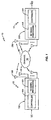
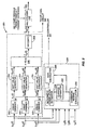
- FIG. 1 illustrates a multiple input/multiple output (MIMO) wireless communication system 10 including a first station 12 and a second station 14.
- the first station 12 includes a transmitter 100 for transmitting signals to the second station 14 over a communication channel 16, while the second station includes a receiver 200 for receiving signals transmitted by the first station 12.
- the first station 12 and second station 14 may each include both a transmitter 100 and receiver 200 for bi-directional communications.
- the first station 12 is a base station in a wireless communication network
- the second station 14 is mobile station.
- the present invention is particularly useful for transmitting data from the base station 12 to the mobile station 14 on the High Speed Downlink Packet Access (HSPDA) channel in WCDMA systems.
- HSPDA High Speed Downlink Packet Access
- An information signal I(t) in the form of a binary data stream is input to the transmitter 100 at the first station 12.
- the transmitter includes a controller 101 and a transmit signal processing circuit 103.
- the controller 101 controls operation of the transmitter 100 and schedules mobile stations 14 to receive data on shared downlink channels.
- the transmit signal processing circuit 103 performs error coding, maps the input bits to complex modulation symbols, and generates transmit signals for each transmit antenna 150, which may be independent, partially redundant, or fully redundant.
- transmitter 100 transmits the transmit signals from respective transmit antennas 150 through the communication channel 16 to the mobile station 14. In the exemplary embodiments described herein, the available transmit power is allocated evenly among all active transmit antennas 150.
- the receiver 200 at the second station 14 demodulates and decodes the signals received at each antenna 250.
- Receiver 200 includes a controller 201 to control operation of the receiver 200 and a receive signal processing circuit 203.
- the receive signal processing circuit 203 demodulates and decodes the signal transmitted from the first station 12. In the absence of bit errors, the output signal from the receiver 200 will be the same as the original information signal input I(t) at the transmitter 100.
- the receiver 200 may for example, comprise a successive interference cancellation (SIC) receiver that successively decodes a plurality of signals contained within a composite signal. Because multiple data streams are transmitted in parallel from different antennas 150, there is a linear increase in throughput with every pair of antennas 150, 250 added to the system without an increase in the bandwidth requirement. MIMO systems have been the subject of extensive research activity worldwide for use in wireless communication networks because of their potential to achieve high spectral efficiencies, and therefore high data rates.
- SIC successive interference cancellation
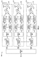
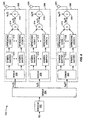
- FIG. 2 illustrates an exemplary transmitter 100 for a MIMO system based on a Per Antenna Rate Control (PARC) architecture.
- PARC is a multiple stream transmitting technique used in wireless communication systems to increase system capacity.
- the transmitter 100 comprises a demultiplexer 102 to divide the original information bit stream I into M bit streams ⁇ b 1 ( t ), b 2 ( t ),... b M ( t ) ⁇ , coding and modulation circuits 104 for each bit stream, and a plurality of antennas 150.
- the coding and modulation circuit 104 for each bit stream ⁇ b 1 ( t ) ,b 2 ( t ), ...b M ( t ) ⁇ comprises an encoder 106 to encode the bit stream ⁇ b 1 ( t ), b 2 ( t ),... b M ( t ) ⁇ , a plurality of demultiplexers 108 to further divide the bit stream ⁇ b 1 ( t ), b 2 ( t ),...
- b M ( t ) ⁇ into substreams, a plurality of symbol mappers 110 to map each substream to points on a signaling constellation, a plurality of signal spreaders 112 to apply a selected spreading code to each substream, and a combiner 114 to recombine the sub-streams to generate a transmit signal ⁇ x 1 ( t ), x 2 ( t ),... x M ( t ) ⁇ for transmission.
- the transmit signals ⁇ x 1 ( t ), x 2 ( t ),... x M ( t ) ⁇ may be further combined by combiner 116 with one or more other simultaneously transmitted signals u m ( t ) that contain a number of dedicated channels and control channels, as well as a common pilot channel.
- the encoders 106 for each bit stream ⁇ b 1 ( t ), b 2 ( t ), ...b M ( t ) ⁇ encode the original information bits at different rates. The rates depend on the channel quality indicator (CQI) feedback from the receiver 200.
- the coded signal output by each encoder 106 is then divided into K substreams by demultiplexers 108. Each substream is mapped to symbols by one of K symbol mappers 110, and spread with one of K spreading codes by signal spreaders 112.
- the K spreading codes may be reused for the different modulation circuits 104.
- the combiner 114 recombines the K spread signals from each signal spreader 112. In the PARC approach shown in Fig. 2 , the number of coded signals and the number of transmit antennas 150 are the same. However, the number of used transmit antennas 150 may vary from one scheduling interval to the next. Furthermore, the subset of used transmit antennas 150 can be optimized by using antenna selection.
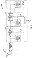
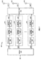
- Fig. 3 illustrates an exemplary SIC receiver 200 for a MIMO system 10.
- the SIC receiver 200 comprises a despreading circuit 205 and a plurality of decoding stages 210.
- the despreading circuit 205 despreads the received composite signal from each receive antenna 250.
- the despreading unit 205 shown in Fig. 4 may be used as a despreading circuit 205 in the SIC receiver 200.
- the received composite signal at each receive antenna 250 comprises M signals of interest transmitted from M transmit antennas 150.
- Each decoding stage 210 decodes one signal of interest transmitted from a respective transmit antenna 150.
- the selection of the decoding order is either signaled by the base station or predetermined based on a mobile station's most recent feedback.
- Multiplexer 246 combines the decoded signals output from each signal decoding stage 210 to produce an estimate Î ( t ) of the original serial information stream I ( t ).
- the despread signals output from the despreading circuit 205 are input to the first signal decoding stage 210.
- the input for each successive signal decoding stage 210 is provided by the previous signal decoding stage 210.
- Each signal decoding stage includes a decoding circuit 220 and an interference cancellation circuit 240.
- the decoding circuit 220 decodes one of the signals of interest.
- the number of signal decoding stages 210 equals the number of used transmit antennas 150.
- the interference cancellation circuit 240 in each decoding stage 210 except for the last decoding stage 210 cancels the decoded signal from the input signal for that signal decoding stage 210 to generate an input signal for the next signal decoding stage 210.
- decoded signals are successively cancelled in each signal decoding stage 210 until only one signal of interest remains by the time the last signal decoding stage 210 is reached.
- the input signals for the first M-1 stages will be composite signals, while the input signal to the last decoding stage 210 contains a single signal of interest, which may be corrupted by residual inference attributable to the previously detected signals of interest that was not completely removed by the previous interference cancellation.
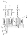
- Fig. 4 illustrates an exemplary despreading circuit 205 for the receiver 200.
- Despreading circuit 205 comprises a plurality of correlator banks 212 and a plurality of sampling units 216.
- Each correlator bank 212 comprises a plurality of correlators 214, also known as RAKE fingers, tuned to one of the K spreading codes and spanning the multiple receive antennas 250.
- a finger placement processor 218 selects the finger delays of the RAKE fingers comprising each correlator bank 212 in the same manner as a conventional single-antenna GRAKE receiver. For example, finger placement processor 218 may place the RAKE fingers to maximize the signal to interference plus noise ratio (SINR) at the output of the GRAKE combining circuit 222.
- SINR signal to interference plus noise ratio
- the RAKE finger outputs are then sampled at the symbol intervals by sampling units 216 to generate a plurality of despread vectors denoted y mk ( i ) at each I th symbol interval.
- the subscript k indicates the code channel and the subscript m indicates the m th stage of the SIC receiver.
- the despread vector y mk (i) represents a composite of M coded signals transmitted from M transmit antennas 150 over the K th code channel.
- Fig. 5 illustrates an exemplary decoding circuit 220 for the m th stage.
- the exemplary decoding circuit 220 uses GRAKE combining which takes into account code impairment correlations and possibly code cross-correlations, but could also use conventional RAKE combining.
- the decoding circuit 220 comprises K GRAKE combiners 222, each of which are matched to the m th antenna, K soft value generators 224, a parallel to serial converter 226, and a decoder 228. There is one GRAKE combiner 222 and one soft value generator 224 for each of the K code channels.
- Each GRAKE combiner 222 combines the despread vector y mk ( i ) using a combining weight vector w mk ( i ) to generate a GRAKE output signal z mk ( i ) that corresponds to one of the data substreams.
- Each soft value generator 224 generates a stream of soft values d mk ( t ) corresponding to the coded bits.
- the combining weight vector w mk ( i ) is computed by a RAKE processor 230.
- RAKE processor 230 comprises a channel estimator 232, an impairment correlation estimator 234, a combining weight calculator 236, and an SINR calculator 238.
- Channel estimator 232 generates channel estimates for the impairment estimator 234 and combining weight calculator 236.
- the impairment correlation estimator 234 calculates impairment correlations that are used by the combining weight calculator 236 based on the channel estimates and spreading codes.
- the combining weight calculator 236 determines the combining weights based on the impairment correlations provided by the impairment correlation estimator 234 and the channel estimates provided by the channel estimator 232.
- the impairment covariance matrix R ym ( k , i ) takes into account cross-correlations between spreading codes used to spread the data substreams d mk ( t ) to reduce intersymbol interference (ISI) and multiple access interference (MAI) due to code reuse.
- ISI intersymbol interference
- MAI multiple access interference
- the impairment covariance matrix R ym ( k,i) is different for each decoding stage 210 due to the successive interference cancellation.
- the net response vector h mk ( i ) will also vary for each transmit antenna 150 making the RAKE combining weights different for each transmit antenna 150.
- the SINR calculator 238 estimates the SINR for one or more transmission modes as hereinafter described based on the impairment covariance matrix R ym ( k , i ) and net response vector h mk ( i ).
- the net response, impairment covariance, and hence combining weights are all functions of the desired symbol's spreading code.
- the GRAKE output signals z mk ( i ) are supplied to respective soft value generators 224.
- Each soft value generator 224 receives a corresponding GRAKE output signal z mk ( i ) and generates soft values d mk ( t ).
- the soft values are input to parallel-to-serial converter 226 which converts the parallel soft value streams into a single serial soft value stream d ⁇ m (t).
- the composite soft value stream d ⁇ m ( t ) is input to a decoder 228 to obtain a decoded bit stream b ⁇ m (t) corresponding to the signal of interest transmitted from the m th transmit antenna 150.
- a second parallel-to-serial converter 246 functions as a multiplexer. Parallel-to-serial converter 246 receives the decoded bit streams b ⁇ m ( t ) for all transmit antennas 150 and outputs an estimate Î ( t ) the original information stream I ( t ).
- transmission mode refers to the number of transmit antennas 150 or streams that will be used to transmit information to the mobile station 14.
- PARC there is a one-to-one correspondence between the number of transmit antennas 150 and streams.
- the transmission mode is designated herein as mode n, where n is the number of transmit antennas 150.
- mode 2 refers to a transmission mode using two transmit antennas 150.
- the "best" subset of transmit antennas 150 should be chosen for transmitting data to the mobile station 14.
- One interpretation of "best” is the subset of transmit antennas 150 that maximizes the data transmission rate.
- the process of determining the subset of transmit antennas 150 to use is known as antenna selection.
- a MIMO transmission scheme having selectively changeable transmission modes is referred to as selective MIMO.
- Mode selection and antenna selection may be performed by the controller 101 at the base station 12, the controller 201 at the mobile station 14, or divided between the base station controller 101 and mobile station controller 201. If both mode selection and antenna selection are performed at the base station controller 101, the mobile station controller 201 would need to feedback the SINR for all possible antenna combinations for all possible modes. Alternatively, the mobile station controller 201 may feedback a channel quality indication (CQI), which is essentially a quantized SINR obtained by mapping the SINR at the mobile station 14 to a corresponding CQI value. The amount of feedback is dependent on the number of transmit antennas 150 being used.
- CQI channel quality indication
- the mobile station 14 would need to feedback one CQI for each of the four mode-1 antenna combinations, two CQIs for each of the six mode-2 antenna combinations, three CQIs for each of the four mode-3 antenna combinations, and four CQIs for the single mode-4 combination, resulting in a total of 32 CQI values.
- the amount of feedback may be reduced by letting the mobile station controller 201 select the best combination of antennas 150 for each possible mode, and letting the base station controller 101 select the transmission mode.
- the mobile station controller 201 determines the combination of transmit antennas 150 for each transmission mode that maximizes the rate and feeds back the SINR or CQI for the selected antennas 150 for each mode.
- this approach requires that the mobile station controller 201 feed back one CQI for mode 1, two CQIs for mode 2, three CQIs for mode 3 and four CQIs for mode 4, for a total of 10 CQIs.
- the mobile station controller 201 would need to feed back the antenna selection for each mode.
- the amount of feedback can be further reduced by constraining the antenna combinations for each lower order mode to be a subset of the antenna combinations for the higher order modes.
- This constraint is referred to herein as the subset property and is described in U.S. Patent Application No. 10/841911 filed 7 May 2004 .
- the mode 2 combination must include antenna 3.
- the possible mode 2 combinations include ⁇ 1, 3 ⁇ , ⁇ 2, 3 ⁇ and ⁇ 4, 3 ⁇ .
- the antenna selection for mode 2 is ⁇ 1, 3 ⁇ .
- the mobile station controller 201 is limited to considering antenna combinations for mode 3 that include antennas 1 and 3, namely ⁇ 2, 1, 3 ⁇ and ⁇ 4, 1, 3 ⁇ .
- the mobile station controller 201 For the highest order mode, the mobile station controller 201 needs to consider only one antenna combination. If the best antenna combination for mode 3 is ⁇ 2, 1, 3 ⁇ , then the mobile station 14 need only consider one antenna combination for mode 4, namely ⁇ 4, 2, 1, 3 ⁇ . If the mobile station controller 201 feeds back the antenna selection for mode 4, the base station 12 can deduce the antenna selection for the lower order modes. Thus, only one antenna selection indicator needs to be fed back to the base station 12. For reasons that will become apparent from the subsequent discussion, the antenna selection also denotes the decoding order.
- Table 1 gives the general form of the SINR for each stage in a SIC receiver 200 when the subset property is used assuming the above described antenna selections.
- the SINR for mode 1 is the largest, and that the first stage SINRs for the downlink transmission modes decrease monotonically when ordered from lowest to highest mode, as discussed further below.
- the SINR is given by the power of the data signal from antenna 3, denoted S 3 , divided by the noise power N , i.e., S 3 / N.
- S 3 the power of the data signal from antenna 3
- N the noise power
- the signal from antenna 1 is decoded followed by the signal from antenna 3.
- the signal from antenna 3 creates interference with the signal from antenna 1.
- SINR 1 1 2 ⁇ S 1 1 2 ⁇ S 3 + N
- the SINR in the second stage of the receiver 200 in mode 2 is the same as the SINR of the first stage in mode 1 with a scale factor applied to account for the fact that the transmit power is equally divided between two transmit antennas 150 in mode 2.
- the mobile station 14 only needs to feed back the first stage SINRs for each transmission mode plus an antenna selection indicator that indicates the decoding order.
- the base station 12 can then construct the SINRs for each stage of each mode by simply scaling the first stage SINRs to account for the equal division of power across the number of antennas used for that mode. Subsequently, the base station 12 can then adjust the constructed SINRs for each stage according to the actual resource allocations and determine the transmission mode that supports the largest data rate.
- the feedback load is reduced to only four SINRs or CQIs and one antenna selection indicator.
- the scheduler at the base station 12 will favor users with the best channel conditions.
- users with favorable channel conditions will be far more likely to be scheduled than users with unfavorable conditions. Exceptions may occur, for example, if a fairness criteria is used to ensure that all users are served.
- Some channel quality feedback from users in unfavorable conditions may be needed if users are to remain in contention for scheduling.
- the cost of feeding back channel quality information may exceed the benefit, even for users with favorable conditions.
- the channel quality information for the higher order transmission modes may not be beneficial if the expected increase in data transmission rate for the higher order transmission modes is negligible. In this case, a substantial reduction in feedback load may be realized by feeding back information only for the lower order transmission modes without any appreciable effect on performance.
- a feedback control mechanism may be implemented by the controller 101 at the base station 12 to control the feedback load from the mobile stations 14.
- Feedback control may be implemented through use of a threshold that can be revised by the controller 101 at the base station 12 to control the feedback load.
- the threshold may be transmitted to the mobile stations 14 over a broadcast channel that is monitored by all of the mobile stations 14.
- the mobile station 14 determines the amount of feedback to send to the base station 12.
- the mobile station 14 may send channel quality feedback for mode 1 regardless of channel conditions.
- Channel quality feedback for higher order modes is based on comparison of a performance metric to the threshold. Thus, feedback for the higher order modes is dependent upon current channel conditions.
- the mobile stations 14 always provide channel quality feedback for the single antenna transmission mode (i.e., mode 1). Whether the mobile station 14 sends feedback for the higher order transmission modes (i.e., transmission modes 2-M) depends on the threshold.
- the base station 12 sends an SINR threshold to the mobile stations 14.
- the mobile stations 14 sharing the HSDPA channel compare the SINR for the single antenna transmission mode to the SINR threshold. If the computed SINR for the single antenna transmission mode exceeds the threshold, the mobile station 14 calculates and feeds back the first stage SINRs for all possible transmission modes. If the SINR for the single antenna transmission mode is not exceeded, the mobile station 14 still feeds back the first stage SINR for the single antenna transmission mode to remain in contention for the shared downlink channel.
- the base station 12 can control the total amount of feedback sent over the uplink so that only the users most likely to be scheduled feed back channel quality information for the higher order transmission modes. If the threshold is set high, only a few users will feed back channel quality information for the higher order transmission modes. As the threshold is reduced, more users will feed back channel quality information for the higher order transmission modes.
- the threshold may be set, for example, based on resource utilization and system capacity. When system load is light, the threshold may be set to a low value. On the other hand, when system load is heavy, the threshold may be increased to reduce the amount of feedback
- the SINR for the single antenna transmission mode is the largest SINR for all possible modes when the subset property is used in the antenna selection process, it is an appropriate metric to use for feedback control. If the SINR for the single antenna transmission mode is low, it is unlikely that the sum data rate for the higher order modes will be any greater than for the single antenna transmission mode. Consequently, there is little need to feed back channel quality feedback for the higher order transmission modes. However, by feeding back only channel quality information for the single antenna transmission mode, a user with poor channel conditions stays in contention for the shared channel. For example, a user with poor channel conditions may be the only one with data in his/her queue so that he/she may be scheduled despite the poor channel conditions. Also, a user with poor channel conditions may, nevertheless, be scheduled if a proportional fairness criterion is applied by the scheduling algorithm. Having the channel quality feedback for at least the single antenna transmission mode enables the base station 12 to schedule the user under such circumstances.
- the mobile station 14 may apply the SINR threshold to each mode greater than mode 1.
- Channel quality feedback is provided to the base station 12 for mode 1.
- the mobile stations 14 successively compare the first stage SINRs for the higher order modes to the threshold, and send channel information for each higher order mode when the first stage SINR exceeds the SINR threshold.
- the mobile stations 14 may provide channel quality feedback for transmission modes 1 and 2 in the case where the SINR threshold falls between the first stage SINR for transmission modes 2 and 3. Because the SINR for mode 3 did not meet the SINR threshold, the mobile station 14 would not need to compute the SINR for mode 4, thus conserving processing power at the mobile station 14.
- the base station 12 also could broadcast a maximum mode indicator that informs the mobile stations 14 to only feed back the first stage SINRs for the transmission modes up to, and including, the value of the indicator if the SINR for the single antenna transmission mode exceeds the SINR threshold. For example, if the maximum mode indicator indicates mode 3, the mobile stations 14 would transmit channel quality feedback to the base station 12 for modes 1 through 3 if the SINR for stage 1 exceeds the SINR threshold.
- a rate increment threshold may be used in addition to, or in place of, the SINR threshold.
- the rate increment threshold specifies a minimum rate increase that must be satisfied before the mobile station 14 is allowed to transmit channel information for the higher order modes.
- all mobile stations 14 provide channel quality feedback for the single antenna transmission mode.
- Figs. 6 and 7 show two additional transmitter architectures which can be used in place of the PARC architecture.
- An SINR threshold or rate increment threshold could be also used with these transmitter architectures to reduce feedback.
- Fig. 6 illustrates an exemplary transmitter 300 according to a second embodiment based on a spatial multiplexing (SM) architecture.
- the transmitter 300 comprises an encoder 302 to encode the original information stream I(t) to generate a coded bitstream, a demultiplexer 304 to divide the coded bitstream into M bitstreams ⁇ b 1 ( t ), b 2 ( t ),... b M ( t ) ⁇ , modulation circuits 306 for each bitstream, and a plurality of transmit antennas 320.
- SM spatial multiplexing
- the modulation circuit 306 for each bitstream comprises a demultiplexer 308 to divide each coded bitstream into a number of substreams, a plurality of symbol mappers 310 to map each substream to a point on a signaling constellation, a plurality of signal spreaders 312 to apply a selected spreading code to each substream, and a combiner 314 to recombine the substreams to generate a transmit signal ⁇ x 1 ( t ), x 2 ( t ),... x M ( t ) ⁇ for transmission to the second station 14.
- x M ( t ) ⁇ may be further combined by combiner 316 with one or more other simultaneously transmitted signals u m ( t ) that contain a number of dedicated channels, control channels, as well as a common pilot channel.
- the transmitter can also adapt the number of bitstreams (mode) according to channel condition and the availability of radio resource. To support this, the mobile station 14 would need to signal back a channel quality corresponding to, for example, the supportable transmission data rate for each possible mode.
- channel quality feedback for higher modes is based on comparison of a performance metric to the threshold. Thus, feedback for the higher order modes is dependent upon current channel condition.
- Fig. 7 illustrates an exemplary transmitter 400 according to a third embodiment based on a matched field transmit diversity (MFTD) architecture.
- the input data stream is transmitted from multiple transmit antennas 420 to receiver 200 with one or more receive antennas 250.
- the input stream is pre-filtered to match the channel between the transmit and receive antennas 420, 250.
- each stream is transmitted from all transmit antennas 420.
- the transmission mode corresponds to the number of streams or transmit signals.
- the pre-filter 412 is used to focus each transmit signal on a selected receive antenna 250.
- the transmitter 400 includes a demultiplexer 402 to divide the information bitstream into a plurality of bitstreams, a coding and modulation circuit 404 for each bitstream, a prefilter 412 matched to the communication channel between the transmitter 400 and the receiver 200, and a plurality of transmit antennas 420.
- Each coding and modulation circuit 404 includes an encoder 406 to encode a corresponding bitstream, a symbol mapper 408 to map the coded bits to modulation symbols, and a signal spreader 410 to apply a selected spreading code to each substream.
- the signals output from the modulation and encoding circuits 404 are the transmit signal s 1 ( t ),...
- the transmit signals s 1 ( t ),.. s N ( t ) are input to a prefilter 412.
- the prefilter 412 filters the transmit signals based on knowledge of the communication channel between the transmitter 400 and the receiver 200. The calculation of the pre-filters 412 is described in co-pending U.S. Patent Application 11/045,877 filed January 28, 2005 , which is incorporated herein by reference.
- the prefilter 412 outputs filtered signals x 1 ( t ),.... x M ( t ) to the antennas 420 for transmission to the receiver 200.
- the value of N can be referred to as the transmission mode.
- the transmitter can adapt the transmission mode according to channel condition and the availability of radio resource.
- the mobile station 14 For each transmit signal, the mobile station 14 needs to signal back a CQI corresponding to, for example, the supportable transmission data rate, as well as channel information needed for the pre-filter 412 to focus the transmit signal.
- channel quality feedback for determining the transmission data rate and channel information needed for the pre-filter 412 for higher modes are based on comparison of a performance metric to the threshold. Thus, feedback for the higher order modes is dependent upon current channel conditions.
- the present invention also works without antenna selection.
- the mobile station 14 can compare the SINR from the last stage, i.e., the SINR with the largest rate. When the SINR from the last stage does not exceed the threshold, mobile station 14 feeds back only one SINR (or a 1-bit indicator) to indicate to the base station to not schedule this mobile station 14.
Applications Claiming Priority (2)
| Application Number | Priority Date | Filing Date | Title |
|---|---|---|---|
| US11/254,172 US8249518B2 (en) | 2003-12-29 | 2005-10-19 | Network controlled feedback for MIMO systems |
| PCT/SE2006/050379 WO2007046758A2 (en) | 2005-10-19 | 2006-10-05 | Network-controlled feedback for mimo systems |
Publications (3)
| Publication Number | Publication Date |
|---|---|
| EP1938473A2 EP1938473A2 (en) | 2008-07-02 |
| EP1938473A4 EP1938473A4 (en) | 2010-10-06 |
| EP1938473B1 true EP1938473B1 (en) | 2014-08-27 |
Family
ID=37962919
Family Applications (1)
| Application Number | Title | Priority Date | Filing Date |
|---|---|---|---|
| EP06799839.3A Active EP1938473B1 (en) | 2005-10-19 | 2006-10-05 | Network-controlled feedback for mimo systems |
Country Status (7)
| Country | Link |
|---|---|
| US (1) | US8249518B2 (zh) |
| EP (1) | EP1938473B1 (zh) |
| JP (1) | JP5038318B2 (zh) |
| CN (1) | CN101297501B (zh) |
| CA (1) | CA2622989C (zh) |
| TW (1) | TWI405424B (zh) |
| WO (1) | WO2007046758A2 (zh) |
Families Citing this family (62)
| Publication number | Priority date | Publication date | Assignee | Title |
|---|---|---|---|---|
| GB0222555D0 (en) * | 2002-09-28 | 2002-11-06 | Koninkl Philips Electronics Nv | Packet data transmission system |
| SE0400370D0 (sv) * | 2004-02-13 | 2004-02-13 | Ericsson Telefon Ab L M | Adaptive MIMO architecture |
| US8045638B2 (en) * | 2004-03-05 | 2011-10-25 | Telefonaktiebolaget Lm Ericsson (Publ) | Method and apparatus for impairment correlation estimation in a wireless communication receiver |
| GB0423567D0 (en) * | 2004-10-23 | 2004-11-24 | Koninkl Philips Electronics Nv | Mimo system and method of operating a mimo system |
| US8054898B2 (en) | 2005-10-12 | 2011-11-08 | Nortel Networks Limited | Multi-user MIMO systems and methods |
| US8437712B2 (en) * | 2005-10-27 | 2013-05-07 | Telecom Italia S.P.A. | Method and system for multiple antenna communications using multiple transmission modes, related apparatus and computer program product |
| CN101395833B (zh) * | 2006-03-03 | 2015-10-14 | 日本电气株式会社 | 多输入多输出通信系统、发射机及其中的分配资源的方法 |
| US20080144562A1 (en) * | 2006-03-16 | 2008-06-19 | Draper Stark C | Cooperative Routing in Wireless Networks using Mutual-Information Accumulation |
| JP4356756B2 (ja) | 2006-04-27 | 2009-11-04 | ソニー株式会社 | 無線通信システム、並びに無線通信装置及び無線通信方法 |
| JP4775288B2 (ja) | 2006-04-27 | 2011-09-21 | ソニー株式会社 | 無線通信システム、無線通信装置及び無線通信方法 |
| US7773557B2 (en) * | 2006-06-08 | 2010-08-10 | Telefonaktiebolaget Lm Ericsson (Publ) | Downlink signaling of transmitter configuration for CQI estimation |
| DE602006004328D1 (de) * | 2006-06-23 | 2009-01-29 | Mitsubishi Electric Inf Tech | Verfahren und Vorrichtung zur Bestimmung von Kanalzustandsinformationen welche von einer ersten zu einer zweiten Telekommunikationsvorrichtung zu übertragen sind |
| JP2008017096A (ja) * | 2006-07-05 | 2008-01-24 | Fujitsu Ltd | 複数アンテナによる送信/受信を行う通信システム、その送信装置及び受信装置 |
| WO2008022449A1 (en) * | 2006-08-22 | 2008-02-28 | Nortel Networks Limited | Multi-antenna scheduling system and method |
| USRE46450E1 (en) * | 2006-08-28 | 2017-06-20 | Koninklijke Philips N.V. | Efficient CQI signaling in MIMO systems with variable numbers of beams |
| US7961810B2 (en) | 2006-09-07 | 2011-06-14 | Texas Instruments Incorporated | Antenna grouping and group-based enhancements for MIMO systems |
| US8412114B2 (en) * | 2006-09-13 | 2013-04-02 | France Telecom | Adaptive method of transmitting and receiving a signal in a multi-antenna system, corresponding transmission and reception devices, computer program products and signal |
| US7729439B2 (en) * | 2006-09-18 | 2010-06-01 | Marvell World Trade Ltd. | Calibration correction for implicit beamforming in a wireless MIMO communication system |
| CN101595670B (zh) * | 2006-11-01 | 2012-05-23 | Lm爱立信电话有限公司 | 基于mimo的无线通信系统中的sinr反馈方法和装置 |
| CN101536353B (zh) | 2006-11-13 | 2014-03-05 | 艾利森电话股份有限公司 | 用于mimo系统中基于导频模式控制信令的方法和装置 |
| US8509724B2 (en) * | 2006-11-29 | 2013-08-13 | Telecom Italia S.P.A. | Switched beam antenna with digitally controlled weighted radio frequency combining |
| WO2008066468A2 (en) * | 2006-11-30 | 2008-06-05 | Telefonaktiebolaget Lm Ericsson (Publ) | Method and arrangement for selection of mimo transmission mode |
| US7751463B2 (en) * | 2006-12-05 | 2010-07-06 | Telefonaktiebolaget Lm Ericsson (Publ) | Method and apparatus for suppressing interference based on channelization code power estimation with bias removal |
| JP4905461B2 (ja) * | 2006-12-14 | 2012-03-28 | 富士通株式会社 | 多入力多出力通信のためのアンテナを選択する制御装置 |
| BRPI0622239A2 (pt) * | 2006-12-20 | 2011-12-27 | Ericsson Telefon Ab L M | mÉtodo e sistema para uma rede de telecomunicaÇço màvel para selecionar uma modalidade de antena a ser usada para comunicaÇço entre uma rede de raio e um terminal màvel operando na modalidade de recepÇço descontÍnua |
| KR101431271B1 (ko) * | 2007-01-12 | 2014-08-20 | 삼성전자주식회사 | 다중 입력 다중 출력 방식의 이동 통신 시스템에서 피드백정보 송수신 방법 및 장치 |
| JP4563415B2 (ja) * | 2007-02-14 | 2010-10-13 | 株式会社エヌ・ティ・ティ・ドコモ | 移動通信システムで使用される基地局装置、ユーザ装置及び方法 |
| CN101663907B (zh) | 2007-03-19 | 2013-04-24 | 艾利森电话股份有限公司 | 利用上行链路许可作为第一或第二类型cqi报告的触发器 |
| KR101365563B1 (ko) * | 2007-03-26 | 2014-02-21 | 퍼듀 리서치 파운데이션 | 다중 사용자 통신 방법에서 피드백 정보 제어 방법 |
| US7965785B2 (en) * | 2007-04-04 | 2011-06-21 | Ntt Docomo, Inc. | Uplink multiple-input-multiple-output (MIMO) and cooperative MIMO transmissions |
| US8295329B2 (en) * | 2007-04-24 | 2012-10-23 | Telefonaktiebolaget Lm Ericsson (Publ) | Efficient computation of soft scaling factors for linear multi-user detector |
| US8054837B2 (en) * | 2007-04-30 | 2011-11-08 | Yim Tu Investments Ltd., Llc | Multiuser scheduling for MIMO broadcast channels with finite rate feedback |
| KR101009417B1 (ko) * | 2007-06-14 | 2011-01-19 | 한국전자통신연구원 | 다중사용자 다중안테나 송수신 시스템 제어를 위한송신기/수신기 및 그 제어 방법 |
| US8160601B2 (en) * | 2007-06-21 | 2012-04-17 | Elektrobit Wireless Communications Ltd. | Method for optimizing spatial modulation in a wireless link and network element thereto |
| KR20100032884A (ko) * | 2007-07-06 | 2010-03-26 | 텔레호낙티에볼라게트 엘엠 에릭슨(피유비엘) | 통신 시스템에서 채널 품질 정보의 통신을 위한 방법 및 구성 |
| US8068877B1 (en) * | 2007-07-20 | 2011-11-29 | Clear Wireless Llc | Systems and methods of antenna selection |
| US8675743B2 (en) * | 2007-08-03 | 2014-03-18 | Apple Inc. | Feedback scheduling to reduce feedback rates in MIMO systems |
| CN102474754B (zh) * | 2007-08-13 | 2015-09-09 | 爱立信电话股份有限公司 | 上行链路资源的改进分配 |
| KR100939353B1 (ko) * | 2007-12-11 | 2010-01-29 | 한국전자통신연구원 | 신호 수신 방법 및 신호 전송 방법 |
| WO2009080057A1 (en) * | 2007-12-19 | 2009-07-02 | Telecom Italia S.P.A. | Method and system for switched beam antenna communications |
| US8351453B2 (en) * | 2007-12-21 | 2013-01-08 | At&T Intellectual Property I, L.P. | Methods and apparatus to allocate shared resources of a high speed packet access channel in a communication network |
| KR101369340B1 (ko) * | 2008-01-25 | 2014-03-26 | 삼성전자주식회사 | 다중안테나 통신시스템에서 피드백 채널을 할당하는 방법및 장치 |
| US8942636B2 (en) * | 2008-01-28 | 2015-01-27 | Qualcomm Incorporated | Adaptive transmission of resource utilization messages based on throughput |
| US8139528B2 (en) | 2008-01-28 | 2012-03-20 | Qualcomm Incorporated | Adaptive transmission of resource utilization messages |
| US8483620B2 (en) * | 2008-02-07 | 2013-07-09 | Qualcomm Incorporated | Asynchronous interference management |
| US9094986B2 (en) | 2008-02-07 | 2015-07-28 | Qualcomm, Incorporated | Synchronous and asynchronous interference management |
| US20090238086A1 (en) * | 2008-03-19 | 2009-09-24 | Telefonaktiebolaget Lm Ericsson (Publ) | Rank Dependent CQI Back-Off |
| KR101537591B1 (ko) * | 2008-04-07 | 2015-07-20 | 엘지전자 주식회사 | Mimo 시스템에서 모드 적응 방법 |
| US20090323872A1 (en) * | 2008-06-30 | 2009-12-31 | Sirius Xm Radio Inc. | Interface between a switched diversity antenna system and digital radio receiver |
| KR101578135B1 (ko) * | 2008-08-29 | 2015-12-16 | 삼성전자주식회사 | 광대역 무선통신 시스템에서 고속 피드백 정보 송수신 장치 및 방법 |
| CN101783776B (zh) * | 2009-01-15 | 2013-04-24 | 华为技术有限公司 | 预编码反馈方法及系统、用户设备和基站 |
| CN101873647B (zh) * | 2009-04-22 | 2012-07-18 | 中兴通讯股份有限公司 | 一种非周期信道质量信息发送方法 |
| CN102056220B (zh) | 2009-10-28 | 2014-02-19 | 华为技术有限公司 | 实现信道测量的方法及装置 |
| GB201006104D0 (en) * | 2010-04-13 | 2010-05-26 | Icera Inc | Decoding a signal |
| JP5682710B2 (ja) * | 2010-09-03 | 2015-03-11 | 富士通株式会社 | Mimo通信ネットワークにおいて使用される方法及びユーザ装置 |
| US8582624B2 (en) * | 2010-10-01 | 2013-11-12 | Telefonaktiebolaget Lm Ericsson (Publ) | Method and apparatus for enhancing the accuracy of the estimated covariance matrix in wideband-CDMA systems |
| US9154969B1 (en) | 2011-09-29 | 2015-10-06 | Marvell International Ltd. | Wireless device calibration for implicit transmit |
| CN105991176B (zh) * | 2015-01-30 | 2019-10-11 | 上海诺基亚贝尔股份有限公司 | 一种用于改善信道质量反馈的方法 |
| FR3047621B1 (fr) * | 2016-02-05 | 2019-04-12 | Institut National Des Sciences Appliquees | Technique de modulation spatiale et dispositif recepteur associe |
| US10594434B2 (en) * | 2016-03-11 | 2020-03-17 | Nokia Technologies Oy | Feedback signaling management |
| CN111246485B (zh) * | 2020-02-27 | 2022-09-20 | 华南理工大学 | 一种高密度车载通信环境下的车联网资源分配方法 |
| US11882626B1 (en) * | 2020-06-10 | 2024-01-23 | Sprint Spectrum Lp | Selecting antenna configurations based on transmission type |
Family Cites Families (19)
| Publication number | Priority date | Publication date | Assignee | Title |
|---|---|---|---|---|
| FI106285B (fi) | 1998-02-17 | 2000-12-29 | Nokia Networks Oy | Mittausraportointi tietoliikennejärjestelmässä |
| FI982763A (fi) | 1998-12-21 | 2000-06-22 | Nokia Networks Oy | Tiedonsiirtomenetelmä ja radiojärjestelmä |
| US6445917B1 (en) | 1999-05-19 | 2002-09-03 | Telefonaktiebolaget Lm Ericsson (Publ) | Mobile station measurements with event-based reporting |
| US7047016B2 (en) * | 2001-05-16 | 2006-05-16 | Qualcomm, Incorporated | Method and apparatus for allocating uplink resources in a multiple-input multiple-output (MIMO) communication system |
| KR100533205B1 (ko) | 2001-10-17 | 2005-12-05 | 닛본 덴끼 가부시끼가이샤 | 이동 통신 시스템, 통신 제어 방법, 이것에 사용되는기지국 및 이동국 |
| KR100493079B1 (ko) * | 2001-11-02 | 2005-06-02 | 삼성전자주식회사 | 고속 순방향 패킷 접속 방식을 사용하는 광대역 부호 분할다중 접속 통신 시스템에서 순방향 채널 품질을 보고하는장치 및 방법 |
| US7076263B2 (en) * | 2002-02-19 | 2006-07-11 | Qualcomm, Incorporated | Power control for partial channel-state information (CSI) multiple-input, multiple-output (MIMO) systems |
| US6862271B2 (en) * | 2002-02-26 | 2005-03-01 | Qualcomm Incorporated | Multiple-input, multiple-output (MIMO) systems with multiple transmission modes |
| WO2004102829A1 (en) * | 2003-05-15 | 2004-11-25 | Lg Electronics Inc. | Method and apparatus for allocating channelization codes for wireless communications |
| KR100575930B1 (ko) | 2003-05-16 | 2006-05-02 | 삼성전자주식회사 | 송신다이버시티를 사용하는 이동통신 시스템에 있어송신다이버시티의 방식 전환 장치 및 방법 |
| JP2005057497A (ja) | 2003-08-04 | 2005-03-03 | Science Univ Of Tokyo | 無線伝送制御方法並びに無線受信装置及び無線送信装置 |
| KR100995031B1 (ko) | 2003-10-01 | 2010-11-19 | 엘지전자 주식회사 | 다중입력 다중출력 시스템에 적용되는 신호 전송 제어 방법 |
| US7120395B2 (en) * | 2003-10-20 | 2006-10-10 | Nortel Networks Limited | MIMO communications |
| JP4864720B2 (ja) * | 2003-12-05 | 2012-02-01 | クアルコム,インコーポレイテッド | 閉ループ多重入出力移動通信システムで送信固有ベクトルを選択してデータを送信する装置及び方法 |
| US7599698B2 (en) * | 2003-12-29 | 2009-10-06 | Telefonaktiebolaget Lm Ericsson (Publ) | Network controlled channel information reporting |
| SE0400370D0 (sv) * | 2004-02-13 | 2004-02-13 | Ericsson Telefon Ab L M | Adaptive MIMO architecture |
| US7339980B2 (en) * | 2004-03-05 | 2008-03-04 | Telefonaktiebolaget Lm Ericsson (Publ) | Successive interference cancellation in a generalized RAKE receiver architecture |
| US20050207367A1 (en) * | 2004-03-22 | 2005-09-22 | Onggosanusi Eko N | Method for channel quality indicator computation and feedback in a multi-carrier communications system |
| US20050250544A1 (en) * | 2004-05-07 | 2005-11-10 | Stephen Grant | Base station, mobile terminal device and method for implementing a selective-per-antenna-rate-control (S-PARC) technique in a wireless communications network |
-
2005
- 2005-10-19 US US11/254,172 patent/US8249518B2/en active Active
-
2006
- 2006-10-05 EP EP06799839.3A patent/EP1938473B1/en active Active
- 2006-10-05 CA CA2622989A patent/CA2622989C/en active Active
- 2006-10-05 CN CN200680039014.8A patent/CN101297501B/zh not_active Expired - Fee Related
- 2006-10-05 JP JP2008536547A patent/JP5038318B2/ja not_active Expired - Fee Related
- 2006-10-05 WO PCT/SE2006/050379 patent/WO2007046758A2/en active Application Filing
- 2006-10-18 TW TW095138450A patent/TWI405424B/zh active
Also Published As
| Publication number | Publication date |
|---|---|
| CN101297501A (zh) | 2008-10-29 |
| US20060079221A1 (en) | 2006-04-13 |
| CA2622989C (en) | 2015-06-02 |
| WO2007046758A2 (en) | 2007-04-26 |
| WO2007046758A3 (en) | 2007-06-14 |
| TW200726111A (en) | 2007-07-01 |
| CN101297501B (zh) | 2015-07-01 |
| CA2622989A1 (en) | 2007-04-26 |
| US8249518B2 (en) | 2012-08-21 |
| EP1938473A4 (en) | 2010-10-06 |
| JP2009513061A (ja) | 2009-03-26 |
| EP1938473A2 (en) | 2008-07-02 |
| TWI405424B (zh) | 2013-08-11 |
| JP5038318B2 (ja) | 2012-10-03 |
Similar Documents
| Publication | Publication Date | Title |
|---|---|---|
| EP1938473B1 (en) | Network-controlled feedback for mimo systems | |
| EP1716655B2 (en) | Adaptive feedback for mimo communication systems | |
| US7542446B2 (en) | Space time transmit diversity with subgroup rate control and subgroup antenna selection in multi-input multi-output communications systems | |
| EP2191587B1 (en) | Base station and method for selecting best transmit antenna(s) for signaling control channel information | |
| EP1745576B1 (en) | Selective per antenna rate control in a wireless communications network | |
| KR100640514B1 (ko) | 다중 안테나를 사용하는 무선 통신 시스템에서 데이터스트림 전송 장치 및 방법 | |
| EP2067279B1 (en) | Downlink signaling of transmitter configuration for cqi estimation | |
| US8213533B2 (en) | Distributed antenna diversity transmission method | |
| US7746800B2 (en) | Flexible rate split method for MIMO transmission | |
| CN100518007C (zh) | 移动通信系统中的自适应发射天线分集装置和方法 | |
| KR100938070B1 (ko) | 다중 안테나 시스템에서의 데이터 송/수신장치 및 방법과이를 제공하는 시스템 | |
| EP1865644B1 (en) | Transmitting apparatus, receiving apparatus, and link adaptation method | |
| EP1508992A2 (en) | Apparatus and method for scheduling resource in a multiuser MIMO radio communication system | |
| JP4981065B2 (ja) | 共有チャネル化符号を有するmimo制御チャネル | |
| KR100961889B1 (ko) | 다중 입력 다중 출력 시스템의 순차적 스케줄링 장치 및 방법 | |
| KR101085627B1 (ko) | 다중 사용자 다중 입출력 통신 시스템의 데이터 전송 방법 | |
| KR20120053583A (ko) | 다중 안테나 무선 통신 시스템에서 공간 다중화 신호 전송 방법 및 장치 |
Legal Events
| Date | Code | Title | Description |
|---|---|---|---|
| PUAI | Public reference made under article 153(3) epc to a published international application that has entered the european phase |
Free format text: ORIGINAL CODE: 0009012 |
|
| 17P | Request for examination filed |
Effective date: 20080401 |
|
| AK | Designated contracting states |
Kind code of ref document: A2 Designated state(s): AT BE BG CH CY CZ DE DK EE ES FI FR GB GR HU IE IS IT LI LT LU LV MC NL PL PT RO SE SI SK TR |
|
| A4 | Supplementary search report drawn up and despatched |
Effective date: 20100902 |
|
| 17Q | First examination report despatched |
Effective date: 20100915 |
|
| DAX | Request for extension of the european patent (deleted) | ||
| GRAP | Despatch of communication of intention to grant a patent |
Free format text: ORIGINAL CODE: EPIDOSNIGR1 |
|
| RIC1 | Information provided on ipc code assigned before grant |
Ipc: H04B 1/712 20110101ALI20130424BHEP Ipc: H04B 7/08 20060101ALI20130424BHEP Ipc: H04L 1/06 20060101ALI20130424BHEP Ipc: H04B 1/7107 20110101ALI20130424BHEP Ipc: H04B 7/04 20060101ALI20130424BHEP Ipc: H04B 7/06 20060101AFI20130424BHEP |
|
| RAP1 | Party data changed (applicant data changed or rights of an application transferred) |
Owner name: UNWIRED PLANET, LLC |
|
| INTG | Intention to grant announced |
Effective date: 20130517 |
|
| GRAS | Grant fee paid |
Free format text: ORIGINAL CODE: EPIDOSNIGR3 |
|
| GRAP | Despatch of communication of intention to grant a patent |
Free format text: ORIGINAL CODE: EPIDOSNIGR1 |
|
| INTG | Intention to grant announced |
Effective date: 20140311 |
|
| RAP1 | Party data changed (applicant data changed or rights of an application transferred) |
Owner name: UNWIRED PLANET INTERNATIONAL LIMITED |
|
| GRAA | (expected) grant |
Free format text: ORIGINAL CODE: 0009210 |
|
| AK | Designated contracting states |
Kind code of ref document: B1 Designated state(s): AT BE BG CH CY CZ DE DK EE ES FI FR GB GR HU IE IS IT LI LT LU LV MC NL PL PT RO SE SI SK TR |
|
| REG | Reference to a national code |
Ref country code: GB Ref legal event code: FG4D |
|
| REG | Reference to a national code |
Ref country code: CH Ref legal event code: EP |
|
| REG | Reference to a national code |
Ref country code: AT Ref legal event code: REF Ref document number: 684940 Country of ref document: AT Kind code of ref document: T Effective date: 20140915 |
|
| REG | Reference to a national code |
Ref country code: IE Ref legal event code: FG4D |
|
| REG | Reference to a national code |
Ref country code: DE Ref legal event code: R096 Ref document number: 602006042865 Country of ref document: DE Effective date: 20141002 |
|
| REG | Reference to a national code |
Ref country code: AT Ref legal event code: MK05 Ref document number: 684940 Country of ref document: AT Kind code of ref document: T Effective date: 20140827 |
|
| REG | Reference to a national code |
Ref country code: LT Ref legal event code: MG4D |
|
| REG | Reference to a national code |
Ref country code: NL Ref legal event code: VDEP Effective date: 20140827 |
|
| PG25 | Lapsed in a contracting state [announced via postgrant information from national office to epo] |
Ref country code: PT Free format text: LAPSE BECAUSE OF FAILURE TO SUBMIT A TRANSLATION OF THE DESCRIPTION OR TO PAY THE FEE WITHIN THE PRESCRIBED TIME-LIMIT Effective date: 20141229 Ref country code: ES Free format text: LAPSE BECAUSE OF FAILURE TO SUBMIT A TRANSLATION OF THE DESCRIPTION OR TO PAY THE FEE WITHIN THE PRESCRIBED TIME-LIMIT Effective date: 20140827 Ref country code: SE Free format text: LAPSE BECAUSE OF FAILURE TO SUBMIT A TRANSLATION OF THE DESCRIPTION OR TO PAY THE FEE WITHIN THE PRESCRIBED TIME-LIMIT Effective date: 20140827 Ref country code: LT Free format text: LAPSE BECAUSE OF FAILURE TO SUBMIT A TRANSLATION OF THE DESCRIPTION OR TO PAY THE FEE WITHIN THE PRESCRIBED TIME-LIMIT Effective date: 20140827 Ref country code: BG Free format text: LAPSE BECAUSE OF FAILURE TO SUBMIT A TRANSLATION OF THE DESCRIPTION OR TO PAY THE FEE WITHIN THE PRESCRIBED TIME-LIMIT Effective date: 20141127 Ref country code: FI Free format text: LAPSE BECAUSE OF FAILURE TO SUBMIT A TRANSLATION OF THE DESCRIPTION OR TO PAY THE FEE WITHIN THE PRESCRIBED TIME-LIMIT Effective date: 20140827 Ref country code: GR Free format text: LAPSE BECAUSE OF FAILURE TO SUBMIT A TRANSLATION OF THE DESCRIPTION OR TO PAY THE FEE WITHIN THE PRESCRIBED TIME-LIMIT Effective date: 20141128 |
|
| PG25 | Lapsed in a contracting state [announced via postgrant information from national office to epo] |
Ref country code: AT Free format text: LAPSE BECAUSE OF FAILURE TO SUBMIT A TRANSLATION OF THE DESCRIPTION OR TO PAY THE FEE WITHIN THE PRESCRIBED TIME-LIMIT Effective date: 20140827 Ref country code: CY Free format text: LAPSE BECAUSE OF FAILURE TO SUBMIT A TRANSLATION OF THE DESCRIPTION OR TO PAY THE FEE WITHIN THE PRESCRIBED TIME-LIMIT Effective date: 20140827 Ref country code: IS Free format text: LAPSE BECAUSE OF FAILURE TO SUBMIT A TRANSLATION OF THE DESCRIPTION OR TO PAY THE FEE WITHIN THE PRESCRIBED TIME-LIMIT Effective date: 20141227 Ref country code: LV Free format text: LAPSE BECAUSE OF FAILURE TO SUBMIT A TRANSLATION OF THE DESCRIPTION OR TO PAY THE FEE WITHIN THE PRESCRIBED TIME-LIMIT Effective date: 20140827 |
|
| PG25 | Lapsed in a contracting state [announced via postgrant information from national office to epo] |
Ref country code: NL Free format text: LAPSE BECAUSE OF FAILURE TO SUBMIT A TRANSLATION OF THE DESCRIPTION OR TO PAY THE FEE WITHIN THE PRESCRIBED TIME-LIMIT Effective date: 20140827 |
|
| PG25 | Lapsed in a contracting state [announced via postgrant information from national office to epo] |
Ref country code: EE Free format text: LAPSE BECAUSE OF FAILURE TO SUBMIT A TRANSLATION OF THE DESCRIPTION OR TO PAY THE FEE WITHIN THE PRESCRIBED TIME-LIMIT Effective date: 20140827 Ref country code: CZ Free format text: LAPSE BECAUSE OF FAILURE TO SUBMIT A TRANSLATION OF THE DESCRIPTION OR TO PAY THE FEE WITHIN THE PRESCRIBED TIME-LIMIT Effective date: 20140827 Ref country code: RO Free format text: LAPSE BECAUSE OF FAILURE TO SUBMIT A TRANSLATION OF THE DESCRIPTION OR TO PAY THE FEE WITHIN THE PRESCRIBED TIME-LIMIT Effective date: 20140827 Ref country code: IT Free format text: LAPSE BECAUSE OF FAILURE TO SUBMIT A TRANSLATION OF THE DESCRIPTION OR TO PAY THE FEE WITHIN THE PRESCRIBED TIME-LIMIT Effective date: 20140827 Ref country code: DK Free format text: LAPSE BECAUSE OF FAILURE TO SUBMIT A TRANSLATION OF THE DESCRIPTION OR TO PAY THE FEE WITHIN THE PRESCRIBED TIME-LIMIT Effective date: 20140827 Ref country code: SK Free format text: LAPSE BECAUSE OF FAILURE TO SUBMIT A TRANSLATION OF THE DESCRIPTION OR TO PAY THE FEE WITHIN THE PRESCRIBED TIME-LIMIT Effective date: 20140827 |
|
| REG | Reference to a national code |
Ref country code: DE Ref legal event code: R097 Ref document number: 602006042865 Country of ref document: DE |
|
| PG25 | Lapsed in a contracting state [announced via postgrant information from national office to epo] |
Ref country code: MC Free format text: LAPSE BECAUSE OF FAILURE TO SUBMIT A TRANSLATION OF THE DESCRIPTION OR TO PAY THE FEE WITHIN THE PRESCRIBED TIME-LIMIT Effective date: 20140827 Ref country code: PL Free format text: LAPSE BECAUSE OF FAILURE TO SUBMIT A TRANSLATION OF THE DESCRIPTION OR TO PAY THE FEE WITHIN THE PRESCRIBED TIME-LIMIT Effective date: 20140827 Ref country code: LU Free format text: LAPSE BECAUSE OF FAILURE TO SUBMIT A TRANSLATION OF THE DESCRIPTION OR TO PAY THE FEE WITHIN THE PRESCRIBED TIME-LIMIT Effective date: 20141005 |
|
| REG | Reference to a national code |
Ref country code: CH Ref legal event code: PL |
|
| PG25 | Lapsed in a contracting state [announced via postgrant information from national office to epo] |
Ref country code: BE Free format text: LAPSE BECAUSE OF NON-PAYMENT OF DUE FEES Effective date: 20141031 |
|
| PLBE | No opposition filed within time limit |
Free format text: ORIGINAL CODE: 0009261 |
|
| STAA | Information on the status of an ep patent application or granted ep patent |
Free format text: STATUS: NO OPPOSITION FILED WITHIN TIME LIMIT |
|
| PG25 | Lapsed in a contracting state [announced via postgrant information from national office to epo] |
Ref country code: CH Free format text: LAPSE BECAUSE OF NON-PAYMENT OF DUE FEES Effective date: 20141031 Ref country code: LI Free format text: LAPSE BECAUSE OF NON-PAYMENT OF DUE FEES Effective date: 20141031 |
|
| 26N | No opposition filed |
Effective date: 20150528 |
|
| REG | Reference to a national code |
Ref country code: FR Ref legal event code: PLFP Year of fee payment: 10 |
|
| PG25 | Lapsed in a contracting state [announced via postgrant information from national office to epo] |
Ref country code: SI Free format text: LAPSE BECAUSE OF FAILURE TO SUBMIT A TRANSLATION OF THE DESCRIPTION OR TO PAY THE FEE WITHIN THE PRESCRIBED TIME-LIMIT Effective date: 20140827 |
|
| PG25 | Lapsed in a contracting state [announced via postgrant information from national office to epo] |
Ref country code: HU Free format text: LAPSE BECAUSE OF FAILURE TO SUBMIT A TRANSLATION OF THE DESCRIPTION OR TO PAY THE FEE WITHIN THE PRESCRIBED TIME-LIMIT; INVALID AB INITIO Effective date: 20061005 Ref country code: BE Free format text: LAPSE BECAUSE OF FAILURE TO SUBMIT A TRANSLATION OF THE DESCRIPTION OR TO PAY THE FEE WITHIN THE PRESCRIBED TIME-LIMIT Effective date: 20140827 Ref country code: TR Free format text: LAPSE BECAUSE OF FAILURE TO SUBMIT A TRANSLATION OF THE DESCRIPTION OR TO PAY THE FEE WITHIN THE PRESCRIBED TIME-LIMIT Effective date: 20140827 |
|
| REG | Reference to a national code |
Ref country code: FR Ref legal event code: PLFP Year of fee payment: 11 |
|
| REG | Reference to a national code |
Ref country code: DE Ref legal event code: R082 Ref document number: 602006042865 Country of ref document: DE Representative=s name: GRUENECKER PATENT- UND RECHTSANWAELTE PARTG MB, DE |
|
| REG | Reference to a national code |
Ref country code: FR Ref legal event code: PLFP Year of fee payment: 12 |
|
| REG | Reference to a national code |
Ref country code: GB Ref legal event code: 732E Free format text: REGISTERED BETWEEN 20180510 AND 20180516 |
|
| REG | Reference to a national code |
Ref country code: FR Ref legal event code: PLFP Year of fee payment: 13 |
|
| PGFP | Annual fee paid to national office [announced via postgrant information from national office to epo] |
Ref country code: FR Payment date: 20221024 Year of fee payment: 17 |
|
| PGFP | Annual fee paid to national office [announced via postgrant information from national office to epo] |
Ref country code: IE Payment date: 20221019 Year of fee payment: 17 Ref country code: GB Payment date: 20221018 Year of fee payment: 17 Ref country code: DE Payment date: 20221028 Year of fee payment: 17 |
|
| P01 | Opt-out of the competence of the unified patent court (upc) registered |
Effective date: 20230523 |