EP1936772A2 - Reststromgeräte - Google Patents
Reststromgeräte Download PDFInfo
- Publication number
- EP1936772A2 EP1936772A2 EP08004354A EP08004354A EP1936772A2 EP 1936772 A2 EP1936772 A2 EP 1936772A2 EP 08004354 A EP08004354 A EP 08004354A EP 08004354 A EP08004354 A EP 08004354A EP 1936772 A2 EP1936772 A2 EP 1936772A2
- Authority
- EP
- European Patent Office
- Prior art keywords
- current
- signal
- imbalance
- test
- degaussing
- Prior art date
- Legal status (The legal status is an assumption and is not a legal conclusion. Google has not performed a legal analysis and makes no representation as to the accuracy of the status listed.)
- Granted
Links
- 230000004044 response Effects 0.000 claims abstract description 4
- 238000012360 testing method Methods 0.000 claims description 97
- 238000004088 simulation Methods 0.000 claims description 8
- 238000012545 processing Methods 0.000 claims description 6
- 230000001965 increasing effect Effects 0.000 claims description 4
- 230000007423 decrease Effects 0.000 claims description 3
- 238000001514 detection method Methods 0.000 claims description 2
- 230000001939 inductive effect Effects 0.000 claims description 2
- 239000004020 conductor Substances 0.000 description 21
- 230000007935 neutral effect Effects 0.000 description 10
- 238000000034 method Methods 0.000 description 7
- 238000004364 calculation method Methods 0.000 description 6
- 238000005259 measurement Methods 0.000 description 5
- 230000008901 benefit Effects 0.000 description 4
- 238000010586 diagram Methods 0.000 description 4
- 238000004519 manufacturing process Methods 0.000 description 4
- 238000004804 winding Methods 0.000 description 4
- 230000001419 dependent effect Effects 0.000 description 3
- 238000009434 installation Methods 0.000 description 3
- 230000035559 beat frequency Effects 0.000 description 2
- 230000006870 function Effects 0.000 description 2
- 238000009413 insulation Methods 0.000 description 2
- 230000007246 mechanism Effects 0.000 description 2
- 238000003825 pressing Methods 0.000 description 2
- 206010014405 Electrocution Diseases 0.000 description 1
- 208000027418 Wounds and injury Diseases 0.000 description 1
- 230000004913 activation Effects 0.000 description 1
- 238000004458 analytical method Methods 0.000 description 1
- 238000013459 approach Methods 0.000 description 1
- 230000015572 biosynthetic process Effects 0.000 description 1
- 238000004422 calculation algorithm Methods 0.000 description 1
- 230000001808 coupling effect Effects 0.000 description 1
- 230000000694 effects Effects 0.000 description 1
- 238000010616 electrical installation Methods 0.000 description 1
- 230000004907 flux Effects 0.000 description 1
- 238000010438 heat treatment Methods 0.000 description 1
- 230000000977 initiatory effect Effects 0.000 description 1
- 239000000696 magnetic material Substances 0.000 description 1
- 239000000463 material Substances 0.000 description 1
- 230000000737 periodic effect Effects 0.000 description 1
- 230000002093 peripheral effect Effects 0.000 description 1
- 230000035699 permeability Effects 0.000 description 1
- 230000008569 process Effects 0.000 description 1
- 230000003252 repetitive effect Effects 0.000 description 1
- 230000035945 sensitivity Effects 0.000 description 1
- 238000003860 storage Methods 0.000 description 1
- 238000003786 synthesis reaction Methods 0.000 description 1
Images


Classifications
-
- H—ELECTRICITY
- H02—GENERATION; CONVERSION OR DISTRIBUTION OF ELECTRIC POWER
- H02H—EMERGENCY PROTECTIVE CIRCUIT ARRANGEMENTS
- H02H3/00—Emergency protective circuit arrangements for automatic disconnection directly responsive to an undesired change from normal electric working condition with or without subsequent reconnection ; integrated protection
- H02H3/26—Emergency protective circuit arrangements for automatic disconnection directly responsive to an undesired change from normal electric working condition with or without subsequent reconnection ; integrated protection responsive to difference between voltages or between currents; responsive to phase angle between voltages or between currents
- H02H3/32—Emergency protective circuit arrangements for automatic disconnection directly responsive to an undesired change from normal electric working condition with or without subsequent reconnection ; integrated protection responsive to difference between voltages or between currents; responsive to phase angle between voltages or between currents involving comparison of the voltage or current values at corresponding points in different conductors of a single system, e.g. of currents in go and return conductors
- H02H3/33—Emergency protective circuit arrangements for automatic disconnection directly responsive to an undesired change from normal electric working condition with or without subsequent reconnection ; integrated protection responsive to difference between voltages or between currents; responsive to phase angle between voltages or between currents involving comparison of the voltage or current values at corresponding points in different conductors of a single system, e.g. of currents in go and return conductors using summation current transformers
- H02H3/334—Emergency protective circuit arrangements for automatic disconnection directly responsive to an undesired change from normal electric working condition with or without subsequent reconnection ; integrated protection responsive to difference between voltages or between currents; responsive to phase angle between voltages or between currents involving comparison of the voltage or current values at corresponding points in different conductors of a single system, e.g. of currents in go and return conductors using summation current transformers with means to produce an artificial imbalance for other protection or monitoring reasons or remote control
- H02H3/335—Emergency protective circuit arrangements for automatic disconnection directly responsive to an undesired change from normal electric working condition with or without subsequent reconnection ; integrated protection responsive to difference between voltages or between currents; responsive to phase angle between voltages or between currents involving comparison of the voltage or current values at corresponding points in different conductors of a single system, e.g. of currents in go and return conductors using summation current transformers with means to produce an artificial imbalance for other protection or monitoring reasons or remote control the main function being self testing of the device
-
- H—ELECTRICITY
- H02—GENERATION; CONVERSION OR DISTRIBUTION OF ELECTRIC POWER
- H02H—EMERGENCY PROTECTIVE CIRCUIT ARRANGEMENTS
- H02H3/00—Emergency protective circuit arrangements for automatic disconnection directly responsive to an undesired change from normal electric working condition with or without subsequent reconnection ; integrated protection
- H02H3/26—Emergency protective circuit arrangements for automatic disconnection directly responsive to an undesired change from normal electric working condition with or without subsequent reconnection ; integrated protection responsive to difference between voltages or between currents; responsive to phase angle between voltages or between currents
- H02H3/32—Emergency protective circuit arrangements for automatic disconnection directly responsive to an undesired change from normal electric working condition with or without subsequent reconnection ; integrated protection responsive to difference between voltages or between currents; responsive to phase angle between voltages or between currents involving comparison of the voltage or current values at corresponding points in different conductors of a single system, e.g. of currents in go and return conductors
- H02H3/33—Emergency protective circuit arrangements for automatic disconnection directly responsive to an undesired change from normal electric working condition with or without subsequent reconnection ; integrated protection responsive to difference between voltages or between currents; responsive to phase angle between voltages or between currents involving comparison of the voltage or current values at corresponding points in different conductors of a single system, e.g. of currents in go and return conductors using summation current transformers
- H02H3/334—Emergency protective circuit arrangements for automatic disconnection directly responsive to an undesired change from normal electric working condition with or without subsequent reconnection ; integrated protection responsive to difference between voltages or between currents; responsive to phase angle between voltages or between currents involving comparison of the voltage or current values at corresponding points in different conductors of a single system, e.g. of currents in go and return conductors using summation current transformers with means to produce an artificial imbalance for other protection or monitoring reasons or remote control
-
- G—PHYSICS
- G01—MEASURING; TESTING
- G01R—MEASURING ELECTRIC VARIABLES; MEASURING MAGNETIC VARIABLES
- G01R19/00—Arrangements for measuring currents or voltages or for indicating presence or sign thereof
- G01R19/10—Measuring sum, difference or ratio
Definitions
- the present invention relates to residual current devices (RCDs). More specifically, it relates to RCDs that have a test facility which, when actuated, causes the device to trip.
- RCDs residual current devices
- RCDs are installed for protection against certain potentially dangerous situations arising in electrical supply installations.
- an electrical supply installation 10 has a number of conductors 11 (typically neutral and live conductors for single phase A.C. supplies and three live conductors or three live and one neutral conductor for three phase A.C. supplies).
- the conductors 11 connect to a load circuit 12 (e.g. a domestic ring main to which appliances are connected).
- A. known RCD 13 operates by disconnecting the supply from the load circuit 12 when an imbalance is detected in the current flowing in the conductors 11. This imbalance is due to current flowing to earth indicating, for example, poor insulation or electrocution of a person.
- the RCD 13 has a current transformer 4 consisting of a toroidal magnetic core surrounding the conductors 11.
- a sensor coil (not shown) is wound around the core so that any imbalance in the current flowing in the conductors 11 causes a sensor signal current 5 to be induced in the sensor coil, which current is proportional to the current imbalance.
- An electronic signal processing circuit 6 analyses the sensor signal current 5 to determine if the current imbalance is at or above a pre-set.trip threshold indicative of a potentially dangerous condition in the supply circuit. The device then trips the circuit by providing power to an actuator 17 to actuate a switch 18 to isolate the supply from the load circuit 12.
- RCD devices are required to be fitted with a test button. Pressing the button causes the device to trip, which allows a person to test satisfactory operation of the device. Activation of the test button closes a contact causing a test circuit to introduce a signal to simulate a residual current so that the whole signal path from the sensor to the switch is included in the test. This may be achieved by the circuit shown in Figure 2 . Some of the current in one of the conductors 21a of live and neutral supply conductors 21 a, 21b flows via a resistor 22 so as to bypass the current transformer 4 when a test button is pressed to close a contact 24. There are many disadvantages with this approach.
- connection of the test circuit to the mains conductors 21 a, 21b is required, which can be mechanically awkward within RCD devices.
- the apparent residual current produced is voltage dependent and also dependent on the tolerance and stability of the resistor 22.
- currents much greater than the trip threshold are induced so as to ensure tripping (typically two and a half times, and in some cases as much as five times, the rated trip value). This tests that the device will operate, but not that it will necessarily operate at the rated trip value.
- no account is taken of any standing residual current already in the circuit. In the test, the device simply adds the test residual current to any standing residual current already present. Again this means that the test is not carried out at the rated trip value.
- the resistor 22 can quickly become very hot and burn.
- the device may be subjected to voltage variations in the supply.
- high voltage pulses that may occur between the live and neutral conductors 21 a, 21b can give rise to arcing at the contact 24.
- RCDs are made with different trip threshold ratings and so the resistor 22 must be changed to suit the threshold, which is inconvenient for production.
- FIG. 3 Another known method of implementing the test function is shown in Figure 3 .
- a magnetic field is introduced into a core 33 of the current transformer 4.
- a second winding 31 is provided on the transformer core 33.
- the winding is placed in series with a resistor 35 in a test circuit between the live conductor 21a and neutral conductor 21b.
- a contact 34 closes the circuit and a test signal current flows through the second winding 31. This will induce a current in the sense coil 32.
- the test signal current is much smaller than the sensor signal current required to trip the device due to current gain in the transformer 4.
- a 100 turn winding means only 1/100 th of the trip threshold current is required to produce an apparent residual current sufficient to cause a trip.
- This method reduces the problem of resistor heating, but does not overcome most of the disadvantages of the previous method, such as supply voltage connection, inaccuracy due to standing residual current, high voltage contact rating and resistor tolerance and stability.
- a residual current device intended for tripping an electrical supply from a circuit to be protected when a residual current imbalance in the circuit exceeds a predetermined threshold rating, the RCD comprising:
- the device may be tested for whether or not the RCD trips at or near the rated value. That is, a successful test indicates that the device is operative to trip at the intended threshold rating. An unsuccessful test is one where the device trips when the imbalance signal is below or above the threshold, this condition indicating that the device is not operating at its rating. The test is therefore more rigorous and accurate than the test provided in prior art devices.
- the sense means may be operative for measuring an amount of any residual current imbalance in the circuit.
- the test means may be operative for calculating a difference value corresponding to the difference between the measured residual current imbalance and the predetermined threshold rating.
- the difference value may be applied such that the increase in the imbalance signal is substantially instantaneous.
- the testing means may be operative to ramp up or progressively increase the imbalance signal from a low or zero value to the predetermined threshold value. This alternative provides for determining the level of current imbalance at whichever level the device trips. This advantageously provides for testing whether the device trips at a level which is less than the predetermined threshold.
- the test means effectively introduces a simulation residual current imbalance into the device so that the sense means senses the sum of any residual current imbalance in the circuit being protected and the simulated residual current.
- the sensor means comprises a current transformer having a sense coil, the imbalance signal being an imbalance sense current induced in the sense coil.
- the means for increasing the imbalance signal may include a test coil, wherein a test current applied to the test coil is operable for introducing the simulation current imbalance in the form of a magnetic field in the transformer, thereby inducing the increase in the imbalance sense current in the sense coil.
- the testing means may be coupled to a processor that monitors the imbalance signal and determines the simulation current imbalance required to increase the imbalance signal to a level that corresponds to the rated value. It is an advantage that, if the processor detects a current imbalance below the rated trip value (a standing current imbalance), then it determines how much to increase the imbalance signal to reach the level that corresponds to the rated trip value, and thereby provides a more accurate test than the prior art devices.
- the processor may include an analogue to digital converter (ADC) for converting the current imbalance signal to a digital form, a micro-controller unit (MCU) for processing the digital signal and for providing a digital output signal, and a digital to analogue converter (DAC) for converting the digital output signal to an analogue test signal.
- ADC analogue to digital converter
- MCU micro-controller unit
- DAC digital to analogue converter
- An advantage of synthesising a waveform for the simulation current imbalance directly from the processor is that it is independent of the electrical supply and any variations therein.
- a further advantage is that the waveform can be synthesised by the processor based on the standing residual current determined from the imbalance signal. This means that whatever waveform, phase angle or frequency the standing residual current has, the processor can synthesise a simulation current imbalance waveform, which, when added to the standing residual current waveform, ensures that the device is tested against the rated value.
- the processor is an integrated circuit in the RCD.
- An integrated circuit is an effective, low cost, space-efficient processor, which is simple to assemble into an RCD.
- a residual current device comprising:
- the degaussing coil may be combined with a test coil forming part of a testing means in a device according to the first aspect of the present invention as defined above.
- Degaussing is a method of removing a remanent magnetic field by driving the transformer core with an alternating field which decreases in amplitude over several cycles.
- Removing remanence means that a device, which has been desensitised due to a remenant magnetic field in the transformer core, can be resensitised and thereby reestablish the device's sensitivity so that it will continue to function in the required manner.
- the device can be re-set after a trip while ensuring that the device will trip again within a very short time if the circuit still has a fault.
- the degaussing signal may be applied to the degaussing coil under the control of a processor.
- the processor may be configured to apply the decaying alternating field at a high frequency so that the degaussing signal is not detectable by the RCD's residual current detection system. This ensures that degaussing is achieved in a very short time and that remanence is removed quickly when re-setting the RCD.
- the RCD must be capable of tripping within a specified number of cycles of the A.C. supply and so the high frequency degaussing signal ensures that remanence is removed in fewer than the specified number of cycles.
- the high frequency degaussing also enables the processor to be configured to control degaussing during normal operation.
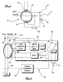
- a power supply installation has a live conductor 40 and a neutral conductor 42, for supplying current from a supply to a load circuit 44.
- An RCD 46 includes a toroidal transformer 48 having a core 50 which surrounds the live and neutral conductors 40, 42.
- a sense coil 52 and a test coil 54 are wound on the core 50.
- a current induced in the sense coil 52 is supplied as an input to an electronic processor 56.
- a switch mechanism 58 actuated by an actuator 60 under the control of the processor 56, breaks the live and neutral conductors 40, 42 when a predetermined level of residual current is detected.
- the input current from the sense coil 52 flows to a transresistance amplifier 59, having a voltage output that is linearly related to the input current.
- the output voltage of the transresistance amplifier 59 is then fed via a lowpass filter 61 (to prevent aliasing) to an analogue-to-digital converter (ADC) 62 which outputs the voltage as a digital electronic signal.
- ADC analogue-to-digital converter
- the digital signal is fed to a micro-controller unit (MCU) 64 via a digital bus 66.
- the MCU 64 has an output 68 for controlling operation of the switch actuator 60.
- the RCD 46 is provided with a test button 70 for closing a contact 72 to initiate a test under the control of the MCU 64.
- a digital test signal provided by the MCU 64 is fed via the bus 66 to a digital-to-analogue converter (DAC) 76, which outputs an analogue test current to the test coil 54.
- DAC digital-to-analogue converter
- a current imbalance between the live and neutral conductors 40, 42 generates a magnetic field which induces a sense current in the sense coil 52.
- the sense current is amplified by the transresistance amplifier 59 and converted into a digital signal by the ADC 62 and read by the MCU 64. If the MCU 64 determines that the current imbalance is above the predetermined rated trip value, then a trip signal is applied to the MCU output 68 such that the switch acuator 60 actuates the switch 58 to break the live and neutral conductors 40, 42, and thereby interrupt electrical supply to the load circuit 44.
- the device may be tested while operational in an untripped condition. Pressing the test button 70 closes the contact 72 and initiates the test.
- the MCU 64 determines the level of the current imbalance being sensed by the sense coil 52, and calculates the amount by which the current from the sense coil 52 must be increased for the RCD 46 to trip at its rated trip value. The calculated increase is provided by means of the test coil 54.
- a test current is provided to the test coil, which generates a magnetic field in the core 50 of the transformer 48. The magnetic field generated induces an increase in the sense current in the sense coil 52.
- the MCU calculates the test current required to test whether or not the RCD trips at the rated value.
- the sense coil 52 is typically 1000 turns of wire and the test coil 54 is typically 100 turns.
- the current in the sense coil 52 is linearly related to the residual current by a factor determined by the turns ratio between the electrical circuit conductors 40, 41 (the primary coil of the transformer) and the sense coil 52. Therefore, a 10mA RMS residual current induces a 10 micro-amp RMS current in the sense coil 52 for the 1:1000 turns ratio.
- a working bandwidth from 20Hz to 2kHz is readily achievable and adequate for RCD purposes.
- the transresistance amplifier 59 is characterized by having low (almost zero) input impedance which is necessary to ensure the sense current is directly related to the residual current by a fixed 1:1000 ratio over the working bandwidth. The output of such an amplifier is a voltage linearly related to the input current with a typical gain of 10000V/A.
- the ADC 62 periodically samples the voltage and each time outputs a digital electronic value of typically 10bits.
- the ADC 62 can be time multiplexed so as to also sample the line voltage of the supply via a potential divider network 74 allowing mains frequency to be monitored.
- the processor 56 measures the frequency of the residual current waveform and the sample frequency is adjusted such that a fixed number of samples per cycle are taken.
- a rate of 64 samples per cycle of the residual at 50Hz gives a sample rate of 3200Hz, whereas at 60Hz the sample rate is 3840Hz.
- An algorithm executed on the MCU 64 determines the frequency of the residual current, but in cases where it cannot be determined (e.g. the amplitude is zero, or the signal is random, or the signal is outside the expected range of values) then the line voltage frequency can be measured and used.
- the digital processing is performed by the MCU 64, which includes control circuitry, arithmetic circuitry, a read/write memory for storage of variable values and a non-volatile read-only memory which stores an executable software program for the whole MCU 64 to follow.
- Other peripheral devices not shown are also present including power supplies, clock circuits and power-on reset circuits.
- the calculation of the residual current RMS is performed over a whole number of cycles to ensure accuracy. Ten cycles of the residual waveform is a sufficient period to perform the calculation and since the sample frequency is adjusted to give a fixed number of samples per cycle (say 64) then the total calculation requires 640 samples. For a 50Hz residual current frequency this therefore takes 200mS to process 640 samples and at 60Hz takes 167mS. In both cases tripping occurs within the time set by published standards.
- the software is written into the MCU 64 at manufacture using a non-volatile memory.
- the non-volatile memory also contains associated configuration data, such as the tripping current threshold and calibration data derived from measurements taken at manufacture.
- the DAC 76 either directly outputs current or otherwise outputs voltage which can be converted to current by a linear current-to-voltage amplifier (transconductance amplifier) or more simply using a fixed resistor.
- the waveshape and amplitude of the current signal produced by this system is controlled by the MCU 64 under software control.
- test current is independent of supply voltage and does not require a high voltage switch, since the test circuit is connected to a low voltage MCU input.
- the test coil 52 in order for the test coil 52 to induce the correct RMS current in the sense coil 52 to produce a trip, it is necessary to determine the waveform of any standing residual current.
- Standing residual currents are usually caused by poor insulation or capacitive suppressor networks often found on motors.
- the waveform will often be a sinewave in phase with the mains voltage but it is possible that it could be up to 90 degrees out of phase if leakage is purely reactive and maybe up to 180 degrees if generating equipment is present in the load circuit.
- non-sinusoidal residual current waveforms are common but will almost always be repetitive at the mains frequency.
- the threshold I n 30mA then it is necessary to drive the test coil to produce an extra 22.4mA RMS measured residual to cause tripping.
- the equation above (which is based on the fact that the resultant RMS of two summed signals is equal to the root of the summed squares of the individual RMS values) assumes the following conditions
- the MCU 64 is capable of measuring the frequency, or in some circumstances it is assumed to be the same as the measured supply frequency.
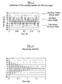
- the test coil 54 can then be driven at a frequency 20 % higher or lower than the measured residual current frequency (e.g. 40 Hz if the measured frequency is 50Hz).
- the resultant is shown in Figure 8 .
- the RMS of the resultant is found to be correct as predicted by Equation 1 above, and will in fact work for any wave shape of standing residual current. It is also true that any wave shape for the test signal can also be used and the use of a square wave test signal rather than a sinusoid can be simpler to synthesise. Another way of looking at this is that the use of different frequencies means that the dependency of the resultant RMS on phase is lost because the two signals are added over time at all combinations of phase.
- Condition "b" above requires measurement of the resultant of the standing and induced test current signals to be performed over a great length of time to achieve accuracy.
- the tripping time at the rated threshold for most RCDs is set at 300ms maximum by the relevant standards. Therefore, when the test button 70 is pressed the device has about 14 mains cycles (280mS) to initiate the trip. This number of cycles does give reasonable accuracy but improved accuracy and tripping time can be achieved with some care.
- a beat frequency is present equal to the difference in the frequencies of standing residual current and test current, in this case 10Hz for a 50Hz residual current.
- test signal is calculated as a fixed percentage of the standing residual current frequency such that over the period where a fixed number of samples are used to calculate the resultant RMS there will be an integer multiple of cycles of the beat frequency produced between the standing residual current and test signal frequencies.
- test current calculation must take into account the turns ratio of the sense and test coils so that the induced current ratio is correct, as well as the wave shape used for the test signal. Also, initial tolerances in the system can be accounted for using calibration values stored in memory at manufacture to modify the test current amplitude.
- Another feature of the device is the ability to effectively counter the problem of remanence described above.
- the remanent magnetic field in the transformer core 50 can be removed by driving the core 50 with an alternating field which decreases in magnitude over several cycles.
- This technique is called degaussing.
- Such a signal can be driven into the test coil 54 to permit degaussing under software control. It is particularly useful to perform degaussing at startup of the device as this is when the core 50 may have been left magnetized following a fault which caused a trip.
- periodic degaussing can be implemented during normal operation if desired, providing it can be done quickly without effecting normal operation of the device.
- a suitable type of waveform is shown in Figure 8 . It consists of a decaying waveform whose initial amplitude is sufficiently high to cause magnetic saturation of the core (i.e. it cannot become more strongly magnetized).
- the wave form has a peak amplitude of around 2A-turns of the test coil 54, so for a 100 turn test coil 54 this means a current of 20mA peak is required.
- the subsequent decaying waveform leaves the core less and less magnetized after each cycle.
- a high frequency waveform of around 10KHz is suitable and a decay rate of 80% per millisecond over a two-millisecond period achieves degaussing in a short time.
- the optimum parameters of the waveform are greatly dependent upon the dimensions and material of the toroidal core. There are no extra components required to perform degaussing as the proposed components of the test circuit of Figure 4 are able to produce the required signal.
- the synthesis of the waveform is undertaken by the MCU 64 under software control.
- the waveshape used need not be sinusoidal as suggested, other shapes such as rectangular waveforms are equally effective and are simpler to synthesize.
Landscapes
- Engineering & Computer Science (AREA)
- Power Engineering (AREA)
- Emergency Protection Circuit Devices (AREA)
- Breakers (AREA)
- Optical Communication System (AREA)
- Transformers For Measuring Instruments (AREA)
- Video Image Reproduction Devices For Color Tv Systems (AREA)
- Testing Of Short-Circuits, Discontinuities, Leakage, Or Incorrect Line Connections (AREA)
- Liquid Crystal Substances (AREA)
Applications Claiming Priority (2)
| Application Number | Priority Date | Filing Date | Title |
|---|---|---|---|
| GBGB0226111.3A GB0226111D0 (en) | 2002-11-08 | 2002-11-08 | Residual current devices |
| EP03772419A EP1561267B1 (de) | 2002-11-08 | 2003-11-10 | Reststromvorrichtungen |
Related Parent Applications (2)
| Application Number | Title | Priority Date | Filing Date |
|---|---|---|---|
| EP03772419.2 Division | 2003-11-10 | ||
| EP03772419A Division EP1561267B1 (de) | 2002-11-08 | 2003-11-10 | Reststromvorrichtungen |
Publications (3)
| Publication Number | Publication Date |
|---|---|
| EP1936772A2 true EP1936772A2 (de) | 2008-06-25 |
| EP1936772A3 EP1936772A3 (de) | 2010-04-07 |
| EP1936772B1 EP1936772B1 (de) | 2013-10-16 |
Family
ID=9947474
Family Applications (2)
| Application Number | Title | Priority Date | Filing Date |
|---|---|---|---|
| EP08004354.0A Expired - Lifetime EP1936772B1 (de) | 2002-11-08 | 2003-11-10 | Reststromgeräte |
| EP03772419A Expired - Lifetime EP1561267B1 (de) | 2002-11-08 | 2003-11-10 | Reststromvorrichtungen |
Family Applications After (1)
| Application Number | Title | Priority Date | Filing Date |
|---|---|---|---|
| EP03772419A Expired - Lifetime EP1561267B1 (de) | 2002-11-08 | 2003-11-10 | Reststromvorrichtungen |
Country Status (11)
| Country | Link |
|---|---|
| US (1) | US7468871B2 (de) |
| EP (2) | EP1936772B1 (de) |
| CN (2) | CN101282035B (de) |
| AT (1) | ATE499735T1 (de) |
| AU (1) | AU2003279470B2 (de) |
| DE (1) | DE60336163D1 (de) |
| DK (1) | DK1936772T3 (de) |
| ES (1) | ES2360497T3 (de) |
| GB (1) | GB0226111D0 (de) |
| WO (1) | WO2004042882A1 (de) |
| ZA (1) | ZA200504653B (de) |
Families Citing this family (48)
| Publication number | Priority date | Publication date | Assignee | Title |
|---|---|---|---|---|
| JP4742232B2 (ja) * | 2005-04-19 | 2011-08-10 | 富士電機株式会社 | 漏電遮断器 |
| DE102006020086A1 (de) * | 2006-04-25 | 2007-10-31 | Siemens Ag | Verfahren und Vorrichtung zur Prüfung von Stromwandlern mittels Hochstromimpuls |
| US8384392B2 (en) * | 2006-11-02 | 2013-02-26 | Texas Instruments Incorporated | Methods and apparatus for continuous ground fault self test |
| AT506346B1 (de) * | 2008-02-14 | 2010-01-15 | Moeller Gebaeudeautomation Gmb | Fehlerstromschutzschalter |
| CN101900771B (zh) * | 2009-05-31 | 2013-11-27 | 西门子公司 | Rcd检测装置和检测方法 |
| US8390297B2 (en) * | 2009-10-02 | 2013-03-05 | Semiconductor Components Industries, Llc | Ground fault circuit interrupter and method |
| ITRM20090527A1 (it) * | 2009-10-12 | 2011-04-13 | Univ Roma | Strumento e metodo di calibrazione per dispositivi di collaudo di interruttori differenziali |
| CN102103160B (zh) * | 2009-12-16 | 2013-07-10 | 中国建筑科学研究院 | 剩余电流监控报警方法、系统与探测控制器 |
| CN101728076B (zh) * | 2010-01-13 | 2011-11-16 | 武汉本杰明自动化设备工程有限公司 | 一种微功耗红外通信的电流互感器 |
| US8810979B2 (en) * | 2010-03-09 | 2014-08-19 | Siemens Industry, Inc. | Method and apparatus for supervisory circuit for ground fault circuit interrupt device |
| US8570181B2 (en) * | 2010-03-15 | 2013-10-29 | Siemens Industry, Inc. | Method and apparatus for supervisory circuit for ground fault circuit interrupt device |
| US8682937B2 (en) * | 2010-05-08 | 2014-03-25 | Lester F. Ludwig | Energy and internal environment management information systems and methods for buildings and campuses |
| EP2407992B1 (de) * | 2010-07-15 | 2013-09-04 | ABB Technology AG | Antriebs- und Steuerungseinheit für eine Nieder- oder Mittelspannungsvorrichtung |
| AT510501A3 (de) * | 2010-09-28 | 2017-02-15 | Eaton Gmbh | Fehlerstromschutzschalter |
| US8907678B2 (en) | 2010-12-10 | 2014-12-09 | Raritan Americas, Inc. | Methods and apparatus for sensing ground leakage and automated self testing thereof |
| CN103380476B (zh) * | 2011-02-16 | 2016-05-25 | 伊顿工业(奥地利)有限公司 | 故障电流保护开关 |
| US20120250206A1 (en) * | 2011-03-30 | 2012-10-04 | General Electric Company | Compact residual current breaker with overcurrent protection |
| CN102761098B (zh) * | 2011-04-28 | 2015-04-01 | 西门子公司 | 剩余电流保护装置及方法 |
| CN103368133B (zh) * | 2012-03-28 | 2016-08-31 | 施耐德电器工业公司 | 具有相线间小电流故障保护的漏电保护断路器 |
| CN106199402A (zh) * | 2012-07-27 | 2016-12-07 | 胡小青 | 用于检测漏电断路器的检测设备 |
| CN106093764A (zh) * | 2012-07-27 | 2016-11-09 | 胡小青 | 一种测试仪 |
| CN105137341A (zh) * | 2012-07-27 | 2015-12-09 | 胡小青 | 对漏电断路器进行测试的测试仪 |
| CN105606995A (zh) * | 2012-07-27 | 2016-05-25 | 胡小青 | 具有时间检测电路的改进型检测设备 |
| US9194888B2 (en) * | 2012-10-11 | 2015-11-24 | Tektronix, Inc. | Automatic probe ground connection checking techniques |
| DE102012220692B4 (de) * | 2012-11-13 | 2019-05-29 | Bender Gmbh & Co. Kg | Verfahren und Vorrichtung zur Überwachung eines Prüfintervalls für eine Fehlerstrom-Schutzeinrichtung |
| DE102013210800A1 (de) | 2013-06-10 | 2014-12-11 | Bender Gmbh & Co. Kg | Integrierte Schaltung mit digitalem Verfahren zur allstromsensitiven Differenzstrommessung |
| CN103337334A (zh) * | 2013-06-20 | 2013-10-02 | 山东电力设备有限公司 | 一种应用于双主柱并联变压器的消磁平衡结构 |
| CN103345872A (zh) * | 2013-07-16 | 2013-10-09 | 南京丹迪克科技开发有限公司 | 一种剩余电流动作保护系统实训装置 |
| ITBO20130405A1 (it) * | 2013-07-26 | 2015-01-27 | Ht Italia S R L | Dispositivo per valutare il corretto funzionamento di unità di protezione di tipo differenziale |
| EP3071986B1 (de) * | 2013-11-18 | 2018-01-03 | e-distribuzione S.p.A. | Stromzähler mit fehlererkennungsmechanismus und fehlererkennungsverfahren |
| EP2910914B1 (de) * | 2014-02-21 | 2018-01-31 | Multipond Wägetechnik GmbH | Wägevorrichtung und Verfahren zum Betreiben der Wägevorrichtung |
| JP6403433B2 (ja) * | 2014-05-28 | 2018-10-10 | スリーエム イノベイティブ プロパティズ カンパニー | 漏液検知器 |
| DE102015008699B4 (de) * | 2015-07-08 | 2017-05-11 | Jenoptik Advanced Systems Gmbh | Fehlerstromsensor für eine Fehlerstrom-Schutzeinrichtung zum Überwachen eines elektrischen Verbrauchers für ein Fahrzeug |
| FR3053174B1 (fr) * | 2016-06-28 | 2018-07-27 | Socomec | Procede de generation d'un courant de court-circuit pour le declenchement d'un element de protection electrique |
| US10333290B2 (en) * | 2016-12-08 | 2019-06-25 | Schneider Electric USA, Inc. | Multi-winding ground fault sensor |
| CN108333540B (zh) * | 2018-02-11 | 2021-08-17 | 中国电力科学研究院有限公司 | 一种用于对计量用电流互感器剩磁进行评估的方法及系统 |
| CN110311654B (zh) * | 2019-07-08 | 2023-05-05 | 深圳开立生物医疗科技股份有限公司 | 一种脉冲纠正方法及脉冲纠正电路 |
| CN110658369A (zh) * | 2019-09-24 | 2020-01-07 | 深圳供电局有限公司 | 剩余电流模拟生成装置及剩余电流动作保护系统 |
| CN110609171B (zh) * | 2019-10-09 | 2022-06-07 | 青岛鼎信通讯股份有限公司 | 基于磁芯工作状态切换下的复杂剩余电流检测方法 |
| EP3812785A1 (de) * | 2019-10-22 | 2021-04-28 | LEM International SA | Fluxgate-stromwandler |
| CN110763903B (zh) * | 2019-11-20 | 2022-04-22 | 国网信息通信产业集团有限公司 | 一种剩余电流检测方法、装置和电路 |
| CN112398085A (zh) * | 2020-11-09 | 2021-02-23 | 贵州电网有限责任公司 | 一种新型高灵敏度剩余电流保护装置 |
| CN112531642B (zh) * | 2020-12-02 | 2023-04-07 | 真兰电气(上海)有限公司 | 一种剩余电流保护电路及剩余电流保护装置 |
| EP4318905B1 (de) | 2021-04-19 | 2025-08-13 | Huawei Digital Power Technologies Co., Ltd. | Gleichstromanschlusskasten, fotovoltaisches stromerzeugungssystem und fehlererkennungsverfahren |
| CN113241725B (zh) * | 2021-05-24 | 2022-12-02 | 常熟开关制造有限公司(原常熟开关厂) | 剩余电流互感器线圈检测方法、装置及剩余电流保护电器 |
| EP4358340A4 (de) | 2021-07-12 | 2024-11-06 | Huawei Digital Power Technologies Co., Ltd. | Stromversorgungssystem, schutzverfahren für stromversorgungssystem und gleichstromwandler |
| US12461127B2 (en) * | 2023-04-14 | 2025-11-04 | Fluke Corporation | Non-contact DC current measurement device with open loop degaussing |
| KR102852372B1 (ko) * | 2023-07-10 | 2025-09-01 | 주식회사 태일테크 | 충전기용 누설 전류 센서의 온도 보상 방법 |
Family Cites Families (22)
| Publication number | Priority date | Publication date | Assignee | Title |
|---|---|---|---|---|
| FR2081183A1 (de) * | 1970-03-16 | 1971-12-03 | Saparel App Ele | |
| US3786356A (en) * | 1972-06-30 | 1974-01-15 | Federal Pacific Electric Co | Ground fault detector |
| JPS59107270A (ja) * | 1982-12-10 | 1984-06-21 | Alps Electric Co Ltd | 直流電流測定センサ |
| US4685024A (en) * | 1985-11-19 | 1987-08-04 | General Electric Company | Overcurrent circuit interrupter using RMS sampling |
| GB2204198B (en) | 1987-03-09 | 1991-04-24 | Qualcast Garden Prod | Residual current circuit breakers |
| US4833564A (en) * | 1987-09-24 | 1989-05-23 | Siemens Energy & Automation, Inc. | Current sensing relay circuit with adjustable sensitivity and tracking test circuit |
| DE3835677C2 (de) * | 1988-10-20 | 1997-07-17 | Metrawatt Gmbh Gossen | Meßverfahren und Schaltungsanordnung zur Ermittlung des Auslösestroms von FI-Schaltern |
| US5652511A (en) * | 1990-07-25 | 1997-07-29 | Leviton Manufacturing Co., Inc. | Method and apparatus for detecting magnetic anomalies in a transformer core by rotating such core through a first winding which impresses a flux field in the core and a second winding to detect magnetic anomalies in the flux established |
| US5459630A (en) * | 1993-09-15 | 1995-10-17 | Eaton Corporation | Self testing circuit breaker ground fault and sputtering arc trip unit |
| AU1885395A (en) | 1994-03-28 | 1995-10-17 | Felten & Guilleaume Austria Ag | Thermal overload protection for switches |
| DE4429949A1 (de) * | 1994-08-24 | 1996-02-29 | Rainer Dipl Phys Berthold | Fehlerstromschutzschalter mit automatischer Überwachungseinrichtung |
| FR2731838B1 (fr) * | 1995-03-16 | 1997-06-06 | Schneider Electric Sa | Appareil electrique de protection differentielle a circuit test |
| DE19636975A1 (de) | 1996-09-12 | 1998-03-19 | Turck Werner Kg | Fehlerstromschutzschalter |
| DE19826410A1 (de) * | 1997-06-17 | 1999-01-07 | Walther Bender Gmbh & Co Kg Di | Verfahren und Einrichtung zur Isolations- und Fehlerstromüberwachung in einem elektrischen Wechselstromnetz |
| US5982593A (en) * | 1998-05-12 | 1999-11-09 | Eaton Corporation | Circuit interrupter with test actuator for ground fault and arc fault test mechanisms |
| US6160697A (en) * | 1999-02-25 | 2000-12-12 | Edel; Thomas G. | Method and apparatus for magnetizing and demagnetizing current transformers and magnetic bodies |
| US6426632B1 (en) * | 1999-03-29 | 2002-07-30 | George A. Spencer | Method and apparatus for testing an AFCI/GFCI circuit breaker |
| DE19940343A1 (de) * | 1999-08-25 | 2001-03-01 | Siemens Ag | Fehlerstrom-Schutzeinrichtung |
| EP1150412A1 (de) * | 2000-04-25 | 2001-10-31 | Siemens Aktiengesellschaft | Fehlerstrom-Schutzschalter und Verfahren zum Überprüfen der Funktionsfähigkeit eines Fehlerstrom-Schutzschalters |
| US6807035B1 (en) * | 2000-11-28 | 2004-10-19 | Hubbell Incorporated | Fault interrupter using microcontroller for fault sensing and automatic self-testing |
| IT1319714B1 (it) * | 2000-12-28 | 2003-11-03 | Abb Ricerca Spa | Interruttore differenziale elettronico di bassa tensione aventefunzionalita' migliorate |
| CN1139165C (zh) * | 2001-04-13 | 2004-02-18 | 常熟开关制造有限公司(常熟开关厂) | 一种用于剩余电流保护的电子控制装置 |
-
2002
- 2002-11-08 GB GBGB0226111.3A patent/GB0226111D0/en not_active Ceased
-
2003
- 2003-11-10 CN CN2008100858483A patent/CN101282035B/zh not_active Expired - Fee Related
- 2003-11-10 WO PCT/GB2003/004833 patent/WO2004042882A1/en not_active Ceased
- 2003-11-10 DK DK08004354.0T patent/DK1936772T3/da active
- 2003-11-10 AU AU2003279470A patent/AU2003279470B2/en not_active Ceased
- 2003-11-10 US US10/535,870 patent/US7468871B2/en not_active Expired - Fee Related
- 2003-11-10 ES ES03772419T patent/ES2360497T3/es not_active Expired - Lifetime
- 2003-11-10 EP EP08004354.0A patent/EP1936772B1/de not_active Expired - Lifetime
- 2003-11-10 AT AT03772419T patent/ATE499735T1/de active
- 2003-11-10 CN CNB2003801077091A patent/CN100477437C/zh not_active Expired - Fee Related
- 2003-11-10 EP EP03772419A patent/EP1561267B1/de not_active Expired - Lifetime
- 2003-11-10 DE DE60336163T patent/DE60336163D1/de not_active Expired - Lifetime
-
2005
- 2005-06-07 ZA ZA2005/04653A patent/ZA200504653B/en unknown
Non-Patent Citations (1)
| Title |
|---|
| None |
Also Published As
| Publication number | Publication date |
|---|---|
| AU2003279470A1 (en) | 2004-06-07 |
| US7468871B2 (en) | 2008-12-23 |
| CN100477437C (zh) | 2009-04-08 |
| CN101282035A (zh) | 2008-10-08 |
| ATE499735T1 (de) | 2011-03-15 |
| GB0226111D0 (en) | 2002-12-18 |
| EP1936772A3 (de) | 2010-04-07 |
| EP1561267A1 (de) | 2005-08-10 |
| WO2004042882A1 (en) | 2004-05-21 |
| EP1561267B1 (de) | 2011-02-23 |
| ES2360497T3 (es) | 2011-06-06 |
| CN1732605A (zh) | 2006-02-08 |
| DK1936772T3 (da) | 2014-01-20 |
| EP1936772B1 (de) | 2013-10-16 |
| US20060158798A1 (en) | 2006-07-20 |
| CN101282035B (zh) | 2012-07-04 |
| DE60336163D1 (de) | 2011-04-07 |
| AU2003279470B2 (en) | 2008-04-10 |
| ZA200504653B (en) | 2014-01-29 |
Similar Documents
| Publication | Publication Date | Title |
|---|---|---|
| EP1561267B1 (de) | Reststromvorrichtungen | |
| AU2002310615B2 (en) | Measuring devices | |
| AU2002310615A1 (en) | Measuring devices | |
| US20090040666A1 (en) | Circuit interrupter including test circuit | |
| EP0890112B1 (de) | Prüfung von elektrischen anlagen | |
| AU2008201173B2 (en) | Residual current devices | |
| CN105359365B (zh) | 用于高中压电力系统中的复杂、通用接地故障保护的方法和装置 | |
| AU2006243066B2 (en) | Circuit protection device and test facility to simulate a fault condition | |
| JP5329470B2 (ja) | 漏洩電流検出装置及び方法 | |
| CN100385761C (zh) | 具有相重构功能的电子跳闸装置和包括该跳闸装置的断路器 | |
| JP3041968B2 (ja) | 低圧系統活線絶縁劣化監視方法 | |
| MXPA05005400A (en) | Residual current devices | |
| EP1591797A1 (de) | Testgerät für Fehlstromschutzschalter | |
| JPH0581862B2 (de) | ||
| JPH02240575A (ja) | 零相電流検出装置 |
Legal Events
| Date | Code | Title | Description |
|---|---|---|---|
| PUAI | Public reference made under article 153(3) epc to a published international application that has entered the european phase |
Free format text: ORIGINAL CODE: 0009012 |
|
| AC | Divisional application: reference to earlier application |
Ref document number: 1561267 Country of ref document: EP Kind code of ref document: P |
|
| AK | Designated contracting states |
Kind code of ref document: A2 Designated state(s): AT BE BG CH CY CZ DE DK EE ES FI FR GB GR HU IE IT LI LU MC NL PT RO SE SI SK TR |
|
| PUAL | Search report despatched |
Free format text: ORIGINAL CODE: 0009013 |
|
| AK | Designated contracting states |
Kind code of ref document: A3 Designated state(s): AT BE BG CH CY CZ DE DK EE ES FI FR GB GR HU IE IT LI LU MC NL PT RO SE SI SK TR |
|
| 17P | Request for examination filed |
Effective date: 20101005 |
|
| AKX | Designation fees paid |
Designated state(s): AT BE BG CH CY CZ DE DK EE ES FI FR GB GR HU IE IT LI LU MC NL PT RO SE SI SK TR |
|
| 17Q | First examination report despatched |
Effective date: 20120926 |
|
| GRAP | Despatch of communication of intention to grant a patent |
Free format text: ORIGINAL CODE: EPIDOSNIGR1 |
|
| INTG | Intention to grant announced |
Effective date: 20130508 |
|
| GRAS | Grant fee paid |
Free format text: ORIGINAL CODE: EPIDOSNIGR3 |
|
| GRAA | (expected) grant |
Free format text: ORIGINAL CODE: 0009210 |
|
| AC | Divisional application: reference to earlier application |
Ref document number: 1561267 Country of ref document: EP Kind code of ref document: P |
|
| AK | Designated contracting states |
Kind code of ref document: B1 Designated state(s): AT BE BG CH CY CZ DE DK EE ES FI FR GB GR HU IE IT LI LU MC NL PT RO SE SI SK TR |
|
| REG | Reference to a national code |
Ref country code: GB Ref legal event code: FG4D |
|
| REG | Reference to a national code |
Ref country code: CH Ref legal event code: EP |
|
| REG | Reference to a national code |
Ref country code: IE Ref legal event code: FG4D |
|
| REG | Reference to a national code |
Ref country code: AT Ref legal event code: REF Ref document number: 636906 Country of ref document: AT Kind code of ref document: T Effective date: 20131115 |
|
| REG | Reference to a national code |
Ref country code: DE Ref legal event code: R096 Ref document number: 60345112 Country of ref document: DE Effective date: 20131212 |
|
| REG | Reference to a national code |
Ref country code: RO Ref legal event code: EPE |
|
| REG | Reference to a national code |
Ref country code: DK Ref legal event code: T3 Effective date: 20140116 |
|
| REG | Reference to a national code |
Ref country code: NL Ref legal event code: T3 |
|
| REG | Reference to a national code |
Ref country code: NL Ref legal event code: T3 |
|
| PG25 | Lapsed in a contracting state [announced via postgrant information from national office to epo] |
Ref country code: FI Free format text: LAPSE BECAUSE OF FAILURE TO SUBMIT A TRANSLATION OF THE DESCRIPTION OR TO PAY THE FEE WITHIN THE PRESCRIBED TIME-LIMIT Effective date: 20131016 Ref country code: SE Free format text: LAPSE BECAUSE OF FAILURE TO SUBMIT A TRANSLATION OF THE DESCRIPTION OR TO PAY THE FEE WITHIN THE PRESCRIBED TIME-LIMIT Effective date: 20131016 Ref country code: BE Free format text: LAPSE BECAUSE OF FAILURE TO SUBMIT A TRANSLATION OF THE DESCRIPTION OR TO PAY THE FEE WITHIN THE PRESCRIBED TIME-LIMIT Effective date: 20131016 |
|
| PGFP | Annual fee paid to national office [announced via postgrant information from national office to epo] |
Ref country code: DK Payment date: 20140128 Year of fee payment: 11 Ref country code: IE Payment date: 20140129 Year of fee payment: 11 Ref country code: RO Payment date: 20140203 Year of fee payment: 11 |
|
| PG25 | Lapsed in a contracting state [announced via postgrant information from national office to epo] |
Ref country code: CY Free format text: LAPSE BECAUSE OF FAILURE TO SUBMIT A TRANSLATION OF THE DESCRIPTION OR TO PAY THE FEE WITHIN THE PRESCRIBED TIME-LIMIT Effective date: 20131016 Ref country code: ES Free format text: LAPSE BECAUSE OF FAILURE TO SUBMIT A TRANSLATION OF THE DESCRIPTION OR TO PAY THE FEE WITHIN THE PRESCRIBED TIME-LIMIT Effective date: 20131016 |
|
| PGFP | Annual fee paid to national office [announced via postgrant information from national office to epo] |
Ref country code: AT Payment date: 20140325 Year of fee payment: 11 |
|
| PG25 | Lapsed in a contracting state [announced via postgrant information from national office to epo] |
Ref country code: PT Free format text: LAPSE BECAUSE OF FAILURE TO SUBMIT A TRANSLATION OF THE DESCRIPTION OR TO PAY THE FEE WITHIN THE PRESCRIBED TIME-LIMIT Effective date: 20140217 |
|
| REG | Reference to a national code |
Ref country code: CH Ref legal event code: PL |
|
| REG | Reference to a national code |
Ref country code: DE Ref legal event code: R097 Ref document number: 60345112 Country of ref document: DE |
|
| PG25 | Lapsed in a contracting state [announced via postgrant information from national office to epo] |
Ref country code: MC Free format text: LAPSE BECAUSE OF FAILURE TO SUBMIT A TRANSLATION OF THE DESCRIPTION OR TO PAY THE FEE WITHIN THE PRESCRIBED TIME-LIMIT Effective date: 20131016 Ref country code: CH Free format text: LAPSE BECAUSE OF NON-PAYMENT OF DUE FEES Effective date: 20131130 Ref country code: EE Free format text: LAPSE BECAUSE OF FAILURE TO SUBMIT A TRANSLATION OF THE DESCRIPTION OR TO PAY THE FEE WITHIN THE PRESCRIBED TIME-LIMIT Effective date: 20131016 Ref country code: LI Free format text: LAPSE BECAUSE OF NON-PAYMENT OF DUE FEES Effective date: 20131130 |
|
| PLBE | No opposition filed within time limit |
Free format text: ORIGINAL CODE: 0009261 |
|
| STAA | Information on the status of an ep patent application or granted ep patent |
Free format text: STATUS: NO OPPOSITION FILED WITHIN TIME LIMIT |
|
| PG25 | Lapsed in a contracting state [announced via postgrant information from national office to epo] |
Ref country code: SK Free format text: LAPSE BECAUSE OF FAILURE TO SUBMIT A TRANSLATION OF THE DESCRIPTION OR TO PAY THE FEE WITHIN THE PRESCRIBED TIME-LIMIT Effective date: 20131016 Ref country code: IT Free format text: LAPSE BECAUSE OF FAILURE TO SUBMIT A TRANSLATION OF THE DESCRIPTION OR TO PAY THE FEE WITHIN THE PRESCRIBED TIME-LIMIT Effective date: 20131016 |
|
| 26N | No opposition filed |
Effective date: 20140717 |
|
| REG | Reference to a national code |
Ref country code: DE Ref legal event code: R097 Ref document number: 60345112 Country of ref document: DE Effective date: 20140717 |
|
| PGFP | Annual fee paid to national office [announced via postgrant information from national office to epo] |
Ref country code: HU Payment date: 20140127 Year of fee payment: 11 |
|
| REG | Reference to a national code |
Ref country code: HU Ref legal event code: AG4A Ref document number: E020783 Country of ref document: HU |
|
| PG25 | Lapsed in a contracting state [announced via postgrant information from national office to epo] |
Ref country code: SI Free format text: LAPSE BECAUSE OF FAILURE TO SUBMIT A TRANSLATION OF THE DESCRIPTION OR TO PAY THE FEE WITHIN THE PRESCRIBED TIME-LIMIT Effective date: 20131016 |
|
| REG | Reference to a national code |
Ref country code: DK Ref legal event code: EBP Effective date: 20141130 |
|
| REG | Reference to a national code |
Ref country code: AT Ref legal event code: MM01 Ref document number: 636906 Country of ref document: AT Kind code of ref document: T Effective date: 20141110 |
|
| PG25 | Lapsed in a contracting state [announced via postgrant information from national office to epo] |
Ref country code: RO Free format text: LAPSE BECAUSE OF NON-PAYMENT OF DUE FEES Effective date: 20141110 Ref country code: BG Free format text: LAPSE BECAUSE OF FAILURE TO SUBMIT A TRANSLATION OF THE DESCRIPTION OR TO PAY THE FEE WITHIN THE PRESCRIBED TIME-LIMIT Effective date: 20131016 Ref country code: LU Free format text: LAPSE BECAUSE OF NON-PAYMENT OF DUE FEES Effective date: 20131110 |
|
| REG | Reference to a national code |
Ref country code: IE Ref legal event code: MM4A |
|
| PG25 | Lapsed in a contracting state [announced via postgrant information from national office to epo] |
Ref country code: GR Free format text: LAPSE BECAUSE OF NON-PAYMENT OF DUE FEES Effective date: 20131016 Ref country code: HU Free format text: LAPSE BECAUSE OF NON-PAYMENT OF DUE FEES Effective date: 20141111 Ref country code: AT Free format text: LAPSE BECAUSE OF NON-PAYMENT OF DUE FEES Effective date: 20141110 |
|
| REG | Reference to a national code |
Ref country code: FR Ref legal event code: PLFP Year of fee payment: 13 |
|
| PG25 | Lapsed in a contracting state [announced via postgrant information from national office to epo] |
Ref country code: DK Free format text: LAPSE BECAUSE OF NON-PAYMENT OF DUE FEES Effective date: 20141130 Ref country code: IE Free format text: LAPSE BECAUSE OF NON-PAYMENT OF DUE FEES Effective date: 20141110 |
|
| PGFP | Annual fee paid to national office [announced via postgrant information from national office to epo] |
Ref country code: GB Payment date: 20151027 Year of fee payment: 13 |
|
| PGFP | Annual fee paid to national office [announced via postgrant information from national office to epo] |
Ref country code: CZ Payment date: 20151030 Year of fee payment: 13 Ref country code: FR Payment date: 20151027 Year of fee payment: 13 Ref country code: NL Payment date: 20151106 Year of fee payment: 13 |
|
| PG25 | Lapsed in a contracting state [announced via postgrant information from national office to epo] |
Ref country code: GR Free format text: LAPSE BECAUSE OF FAILURE TO SUBMIT A TRANSLATION OF THE DESCRIPTION OR TO PAY THE FEE WITHIN THE PRESCRIBED TIME-LIMIT Effective date: 20140117 |
|
| REG | Reference to a national code |
Ref country code: NL Ref legal event code: MM Effective date: 20161201 |
|
| GBPC | Gb: european patent ceased through non-payment of renewal fee |
Effective date: 20161110 |
|
| PG25 | Lapsed in a contracting state [announced via postgrant information from national office to epo] |
Ref country code: CZ Free format text: LAPSE BECAUSE OF NON-PAYMENT OF DUE FEES Effective date: 20161110 |
|
| REG | Reference to a national code |
Ref country code: FR Ref legal event code: ST Effective date: 20170731 |
|
| PG25 | Lapsed in a contracting state [announced via postgrant information from national office to epo] |
Ref country code: TR Free format text: LAPSE BECAUSE OF NON-PAYMENT OF DUE FEES Effective date: 20141110 |
|
| PG25 | Lapsed in a contracting state [announced via postgrant information from national office to epo] |
Ref country code: NL Free format text: LAPSE BECAUSE OF NON-PAYMENT OF DUE FEES Effective date: 20161201 |
|
| PG25 | Lapsed in a contracting state [announced via postgrant information from national office to epo] |
Ref country code: FR Free format text: LAPSE BECAUSE OF NON-PAYMENT OF DUE FEES Effective date: 20161130 |
|
| PG25 | Lapsed in a contracting state [announced via postgrant information from national office to epo] |
Ref country code: GB Free format text: LAPSE BECAUSE OF NON-PAYMENT OF DUE FEES Effective date: 20161110 |
|
| REG | Reference to a national code |
Ref country code: DE Ref legal event code: R081 Ref document number: 60345112 Country of ref document: DE Owner name: EATON INTELLIGENT POWER LIMITED, IE Free format text: FORMER OWNER: EATON ELECTRIC LTD., WORSLEY, MANCHESTER, GB |
|
| PGFP | Annual fee paid to national office [announced via postgrant information from national office to epo] |
Ref country code: DE Payment date: 20191021 Year of fee payment: 17 |
|
| REG | Reference to a national code |
Ref country code: DE Ref legal event code: R119 Ref document number: 60345112 Country of ref document: DE |
|
| PG25 | Lapsed in a contracting state [announced via postgrant information from national office to epo] |
Ref country code: DE Free format text: LAPSE BECAUSE OF NON-PAYMENT OF DUE FEES Effective date: 20210601 |