EP1936743B1 - Doppelanschluss-Schraubstecker für eine elektrische Vorrichtung - Google Patents
Doppelanschluss-Schraubstecker für eine elektrische Vorrichtung Download PDFInfo
- Publication number
- EP1936743B1 EP1936743B1 EP07123026A EP07123026A EP1936743B1 EP 1936743 B1 EP1936743 B1 EP 1936743B1 EP 07123026 A EP07123026 A EP 07123026A EP 07123026 A EP07123026 A EP 07123026A EP 1936743 B1 EP1936743 B1 EP 1936743B1
- Authority
- EP
- European Patent Office
- Prior art keywords
- terminal
- terminal block
- strip spring
- cage
- spring
- Prior art date
- Legal status (The legal status is an assumption and is not a legal conclusion. Google has not performed a legal analysis and makes no representation as to the accuracy of the status listed.)
- Active
Links
- 239000004020 conductor Substances 0.000 claims description 26
- 238000003780 insertion Methods 0.000 claims description 21
- 230000037431 insertion Effects 0.000 claims description 21
- 239000002184 metal Substances 0.000 claims description 3
- 230000006978 adaptation Effects 0.000 description 1
- 239000000463 material Substances 0.000 description 1
- 238000012986 modification Methods 0.000 description 1
- 230000004048 modification Effects 0.000 description 1
Images


Classifications
-
- H—ELECTRICITY
- H01—ELECTRIC ELEMENTS
- H01R—ELECTRICALLY-CONDUCTIVE CONNECTIONS; STRUCTURAL ASSOCIATIONS OF A PLURALITY OF MUTUALLY-INSULATED ELECTRICAL CONNECTING ELEMENTS; COUPLING DEVICES; CURRENT COLLECTORS
- H01R4/00—Electrically-conductive connections between two or more conductive members in direct contact, i.e. touching one another; Means for effecting or maintaining such contact; Electrically-conductive connections having two or more spaced connecting locations for conductors and using contact members penetrating insulation
- H01R4/28—Clamped connections, spring connections
- H01R4/30—Clamped connections, spring connections utilising a screw or nut clamping member
- H01R4/36—Conductive members located under tip of screw
- H01R4/363—Conductive members located under tip of screw with intermediate part between tip and conductive member
-
- H—ELECTRICITY
- H01—ELECTRIC ELEMENTS
- H01H—ELECTRIC SWITCHES; RELAYS; SELECTORS; EMERGENCY PROTECTIVE DEVICES
- H01H71/00—Details of the protective switches or relays covered by groups H01H73/00 - H01H83/00
- H01H71/08—Terminals; Connections
-
- H—ELECTRICITY
- H01—ELECTRIC ELEMENTS
- H01R—ELECTRICALLY-CONDUCTIVE CONNECTIONS; STRUCTURAL ASSOCIATIONS OF A PLURALITY OF MUTUALLY-INSULATED ELECTRICAL CONNECTING ELEMENTS; COUPLING DEVICES; CURRENT COLLECTORS
- H01R4/00—Electrically-conductive connections between two or more conductive members in direct contact, i.e. touching one another; Means for effecting or maintaining such contact; Electrically-conductive connections having two or more spaced connecting locations for conductors and using contact members penetrating insulation
- H01R4/28—Clamped connections, spring connections
- H01R4/48—Clamped connections, spring connections utilising a spring, clip, or other resilient member
- H01R4/4809—Clamped connections, spring connections utilising a spring, clip, or other resilient member using a leaf spring to bias the conductor toward the busbar
- H01R4/48185—Clamped connections, spring connections utilising a spring, clip, or other resilient member using a leaf spring to bias the conductor toward the busbar adapted for axial insertion of a wire end
- H01R4/4819—Clamped connections, spring connections utilising a spring, clip, or other resilient member using a leaf spring to bias the conductor toward the busbar adapted for axial insertion of a wire end the spring shape allowing insertion of the conductor end when the spring is unbiased
- H01R4/4821—Single-blade spring
-
- H—ELECTRICITY
- H01—ELECTRIC ELEMENTS
- H01R—ELECTRICALLY-CONDUCTIVE CONNECTIONS; STRUCTURAL ASSOCIATIONS OF A PLURALITY OF MUTUALLY-INSULATED ELECTRICAL CONNECTING ELEMENTS; COUPLING DEVICES; CURRENT COLLECTORS
- H01R4/00—Electrically-conductive connections between two or more conductive members in direct contact, i.e. touching one another; Means for effecting or maintaining such contact; Electrically-conductive connections having two or more spaced connecting locations for conductors and using contact members penetrating insulation
- H01R4/28—Clamped connections, spring connections
- H01R4/48—Clamped connections, spring connections utilising a spring, clip, or other resilient member
- H01R4/4809—Clamped connections, spring connections utilising a spring, clip, or other resilient member using a leaf spring to bias the conductor toward the busbar
- H01R4/4846—Busbar details
- H01R4/485—Single busbar common to multiple springs
Definitions
- the present disclosure relates generally to a multi-terminal block for electric devices, having two superimposed connecting levels for conductors, which can be used independent of each other.
- the double terminal connection of the present disclosure is used in MiniCircuit Breakers (MCB) and Residual Current Circuit Breakers (RCCB), wherein the terminal has two independent connections, i.e., a cage screw type and a second pin plug-in.
- the second terminal is preferably designed to connect a pin busbar without a screw, instead utilizes a metal sheet spring, with a shape that resembles the number "5".
- the plug-in is surrounded by the terminal cage belonging to the screw type connection. In order to access to the bladespring the pin busbar goes through the window of the terminal.
- Conventional double connection terminals for use in electrical circuit breakers typically require two terminal cage screw busbars.
- Conventional terminals in the electric circuit breakers typically require a terminal cage screw busbars without the possibility to have a quick insertion connection, neither have both types; cage terminal for cables or screwed busbar and quick connection.
- a double connection terminal strip for a modular electrical apparatus is provided with two superimposed levels for connecting conductors capable of being used independently of each other, a first terminal strip of the cage type cooperating with a terminal and a member for clamping/releasing the conductor, accessible from the front surface of the housing of the apparatus including a control lever, the second terminal strip being of the fast-connect type with elastic elements and a without clamping member, the second terminal strip being arranged between the front surface for access to the clamping/releasing member and the cage for connecting the first terminal strip, and being self-supporting by the latter so as not to transmit stresses to the housing.
- a first terminal block comprises a cage screw type conductor connector for securing a first conductor
- a second terminal block comprises a screwless, quick connecting type conductor connector including a strip spring for securing a second conductor.
- a multi-terminal block for electric devices comprising two superimposed connecting levels for conductors, which can be used independent of each other, the multi-terminal block comprising: a terminal (3); a first terminal block comprising a cage screw type conductor connector which comprises a cage and a screw for use securing a first conductor, wherein the first terminal block cooperates with the terminal; and a second terminal block comprising a quick connecting type conductor connector, wherein the quick connecting type conductor connector comprises a strip spring for securing a second conductor, wherein the screw does not extend through the second terminal block and wherein the second terminal block is partially disposed within the cage such that the second terminal block cooperates with the terminal, wherein the terminal comprises an insertion window that communicates with the second terminal block.
- a pin type busbar is disposed within the insertion window and the second terminal block.
- the strip spring is formed of a sheet metal spring and has a shape that resembles the number "5".
- the strip spring comprises a free end which is elastically supported on a surface of the terminal substantially parallel to the axis of the insertion window. Additionally, the strip spring comprises a plurality of wings which holds the strip spring parallel to the axis of the insertion window.
- the strip spring also preferably has a plurality of legs that hold the strip spring inside the second terminal block.
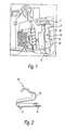
- Figs. 1-4 depict a double connection terminal block, with two independent connection types for cable connection 16.
- the first terminal connection block 1 is a cage type that cooperates with terminal 3, second terminal block 2 being of rapid connection type with spring element 4.
- Second terminal 2 is surrounded partially by cage 5 of first terminal 3 and its accessible through window 6 in front side of the terminal.
- Second terminal 2 is characterized in that the spring allocation cavity 4 is below screw 7.
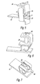
- second terminal block 2 has a strip spring type 10 whose free end 12 is elastically supported on one surface of terminal 3 parallel to the insertion window (6) axis.
- strip spring 10 has two wings 17 that hold the spring parallel to insertion window 6 axis.
- strip spring 10 has two legs 8 that hold strip spring 10 inside terminal cavity avoiding that the strip spring displaces in the insertion direction.
- strip spring 10 has a shape that resembles the number "5". This configuration allows for the first bend that meets a pin busbar indicates to the installer that the pin busbar is in the right place by giving some resistance to the pin insertion (at this stage the installer can see some pin busbar surface outside the apparatus).
- the installer should press the pin more forcefully in order to insert it properly (at this stage the installer cannot see any pin busbar surface outside the apparatus). It is the second bend that will press the pin busbar against the terminal, and it makes the contact force in order to have a proper electrical connection.
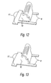
- Figs. 12 and 13 depict optional strip spring configurations, i.e. a flexible "L” shaped strip spring and a less flexible “L” shaped strip spring, respectively.
- Second connection terminal block 2 is for pin busbar 9 is enters via busbar inserts 14,15.
- First terminal block 1 is the cage type cooperating with one fixed terminal and screw 7 for tightening and loosening the conductor, which is accessible from the front surface of the device facing the user in the installed condition, i.e. that which has a operating handle/toggle.
- Second terminal block 2 is of the quick connecting type based on an elastic element and without tightening part.
- Double connections on the same lateral side of an electric device require adaptation to the terminals or a particular order in the relative arrangement of these terminals so that their respective spaces are separated.
- Traditional cage and screw type terminals have mechanical parts which extend up to the front surface of the box, the quick connection type of terminals are arranged inside the cage and below the tip of the screw but away from the space for cable insertion.
- a quick connection type terminal arranged towards a front surface and a screw clamp arrangement towards a fixing side of electric device as a bridging comb and access to it is as easy as possible and consequently is not burdened by other connections present in the foreground and using the terminals closest to the surface of the product.
- Second terminal block 2 is arranged between the front surface, below the tip of screw 7 of the first standard terminal and inside its connection cage, and is selfsupported by fixed terminal so as not to transmit any load to the electric device.
- a modular device provided with two levels on superimposed levels are provided so that the quick connection level is reserved for the supply and for the electrical distribution of the product, by direct plugging/pining of the conductors which preferably are of the bridging rod type.
- the traditional level includes the cage united with a fixed terminal is preferably reserved for the supply of current, by cable or also by bridging rod.
- the second terminal block can be of the strip spring type, whose free end is elastically supported on a surface of the fixed terminal parallel to the axis of insertion of the conductors,
- the strip spring is fixed to a lower leg of the fixed terminal, whereas its free end is supported by added flat portion of fixed terminal which is parallel to the axis of insertion of a conductor, and forms with extension of one of two side edges of the fixed terminal and bent twice inwardly to form close loop with another side edge extended normal the lower leg of fixed terminal.
- the flat potion is, in addition, provided stopper for the screw component, so as to organize the relative motion between the fixed terminal and cage of the first terminal
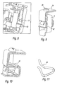
- the strip spring 20 is directly fixed to terminal connector 22, on a portion of the shape parallel to the axis of insertion of the conductors, however, fixed terminal 24 and terminal connector 22 are two different parts, rigidly held by a housing, fixed terminal 24 can be made of stronger and cost effective material than terminal connector 22 which is of course conductive.
- strip spring 20 is of course different from that which used in the embodiment shown in Figs. 1-4 .
- Strip spring 20 is held by terminal connector 22.
- Lines 21 and 23 show the busbar insertion point and cable connection slot, respectively.
- Fig. 6 depicts screw 26 having a stopping point 28.
- Fig. 7 depicts terminal connector 22 with a pair of strip springs 20 disposed between a V-shaped leg support 30 which receives a clamping force during cable connection.
- Figs. 8-11 depict yet another embodiment, wherein the second terminal is of the stab and spring wire type 40.
- stab has double thickness, forms with folding one over other, one of whose ends is supported by a housing 42.
- the end is similar to fixed terminal 24.
- Central opening is made for opening/tightening part.
- Other end forms two branches, which are closely held by spring wire 40 with a provided opening for insertion of conductor 23.
- Figs. 14a-d show an embodiment, wherein the strip spring is rotated 180 degrees. Therefore, insertion window 6 is moved down, close to the cable insertion area, i.e., second terminal block 2.
Landscapes
- Connections Arranged To Contact A Plurality Of Conductors (AREA)
- Multi-Conductor Connections (AREA)
- Details Of Connecting Devices For Male And Female Coupling (AREA)
Claims (7)
- Mehrfach-Anschlussklemmblock für elektrische Geräte, der zwei übereinander liegende Anschlussniveaus für Leiter aufweist, welche unabhängig voneinander benutzt werden können, wobei der Mehrfach-Anschlussklemmbock aufweist:Eine Anschlussklemme (3);einen ersten Anschlussklemmblock (1), der ein Leiteranschlusselement des Käfig/Schraube-Typs aufweist, welches ein Käfig (5) und eine Schraube (7), die zur Befestigung eines ersten Leiters dienen, aufweist, wobei der erste Anschlussklemmblock mit der Klemme (3) zusammenwirkt; undeinen zweiten Anschlussklemmbock (2), der einen Leiteranschlusselement des Schnellanschlusstyps aufweist, wobei das Leiteranschlusselement des Schnellanschlusstyps eine Bandfeder (10) zur Befestigung eines zweiten Leiters aufweist, wobei die Schraube sich nicht durch den zweiten Klemmblock hindurch erstreckt und wobei der zweite Klemmblock teilweise in dem Käfig angeordnet ist, derart, dass der zweite Klemmblock mit der Klemme zusammenwirkt; dadurch gekennzeichnet, dassdie Klemme (3) ein Einführfenster (6) aufweist, das mit der zweiten Klemmblock (2) in Verbindung steht.
- Mehrfach-Anschlussklemmblock nach Anspruch 1, bei der die Bandfeder eine der Ziffer "5" ähnliche Gestalt aufweist.
- Mehrfach-Anschlussklemmblock nach Anspruch 1 oder 2, bei der die Bandfeder eine metallische Bandfeder ist.
- Mehrfach-Anschlussklemmblock nach Anspruch 1, 2 oder 3, bei der eine stiftartige Sammelschiene (9) in dem Einführfenster (6) und dem zweiten Klemmblock (2) angeordnet ist.
- Mehrfach-Anschlussklemmblock nach einem der Ansprüche 1 bis 4, bei der die Bandfeder ein freies Ende (12) aufweist, das im Wesentlichen parallel zu der Achse des Einführfensters auf einer Oberfläche der Klemme elastisch abgestützt ist.
- Mehrfach-Anschlussklemmblock nach Anspruch 5, bei der die Bandfeder mehrere Flügel (17) aufweist, die die Bandfeder parallel zur Achse des Einführfensters halten.
- Mehrfach-Anschlussklemmblock nach einem der Ansprüche 1 bis 6, bei der die Bandfeder eine Anzahl Schenkel (8) aufweist, die die Bandfeder in dem zweiten Anschlussklemmbock halten.
Priority Applications (1)
| Application Number | Priority Date | Filing Date | Title |
|---|---|---|---|
| PL07123026T PL1936743T3 (pl) | 2006-12-21 | 2007-12-12 | Śrubowo/wtykowe podwójne złącze z zaciskiem dla urządzeń elektrycznych |
Applications Claiming Priority (1)
| Application Number | Priority Date | Filing Date | Title |
|---|---|---|---|
| US11/643,466 US7384317B1 (en) | 2006-12-21 | 2006-12-21 | Multi-terminal block for electronic devices having superimposed conductor connecting levels |
Publications (3)
| Publication Number | Publication Date |
|---|---|
| EP1936743A2 EP1936743A2 (de) | 2008-06-25 |
| EP1936743A3 EP1936743A3 (de) | 2011-08-24 |
| EP1936743B1 true EP1936743B1 (de) | 2012-11-07 |
Family
ID=39087808
Family Applications (1)
| Application Number | Title | Priority Date | Filing Date |
|---|---|---|---|
| EP07123026A Active EP1936743B1 (de) | 2006-12-21 | 2007-12-12 | Doppelanschluss-Schraubstecker für eine elektrische Vorrichtung |
Country Status (5)
| Country | Link |
|---|---|
| US (1) | US7384317B1 (de) |
| EP (1) | EP1936743B1 (de) |
| ES (1) | ES2397375T3 (de) |
| NO (1) | NO20076227L (de) |
| PL (1) | PL1936743T3 (de) |
Families Citing this family (16)
| Publication number | Priority date | Publication date | Assignee | Title |
|---|---|---|---|---|
| DE102008020511A1 (de) * | 2008-04-23 | 2009-11-05 | Mc Technology Gmbh | Kontaktelement für eine Anschlussklemme, Anschlussklemme und Steckbrücke für ein Kontaktelement |
| JP5231201B2 (ja) * | 2008-12-25 | 2013-07-10 | スリーエム イノベイティブ プロパティズ カンパニー | 端子台及び該端子台の組立方法 |
| TW201036278A (en) * | 2009-03-27 | 2010-10-01 | Furutech Co Ltd | Stereo wire connector |
| EP2541685B1 (de) * | 2011-06-30 | 2013-12-25 | Siemens Aktiengesellschaft | Schirmanschlussklemme |
| WO2013110363A1 (de) * | 2012-01-26 | 2013-08-01 | Pepperl + Fuchs Gmbh | Zugfeder-schraub-klemme |
| FR2986664B1 (fr) * | 2012-02-03 | 2014-02-14 | Abb France | Borne de raccordement electrique |
| DE102012219741A1 (de) * | 2012-10-29 | 2014-04-30 | Tyco Electronics Amp Gmbh | Elektrischer Kontakt und Steckverbinder mit einem solchen elektrischen Kontakt |
| US9184013B2 (en) | 2013-06-21 | 2015-11-10 | General Electric Company | Conductor guide member for a circuit breaker terminal assembly |
| TWI488370B (zh) * | 2013-07-01 | 2015-06-11 | Alltop Technology Co Ltd | 電連接器 |
| CN105552578B (zh) * | 2016-02-05 | 2018-12-25 | 马晓明 | 导电线连接头及导电线的插接方法 |
| DE102016114289A1 (de) * | 2016-08-02 | 2018-02-08 | Phoenix Contact Gmbh & Co. Kg | Elektrische Anschlussklemme |
| BE1025936B1 (de) * | 2018-01-22 | 2019-08-21 | Phoenix Contact Gmbh & Co Kg | Baukastensystem zum Herstellen eines elektrischen Geräts |
| CN208738447U (zh) * | 2018-07-25 | 2019-04-12 | 施耐德电气(澳大利亚)有限公司 | 用于电气设备的端子组件以及电气设备 |
| US11239652B2 (en) * | 2018-12-26 | 2022-02-01 | Eaton Intelligent Power Limited | Compliant, hazardous environment circuit protection devices, systems and methods |
| AU2021101027A4 (en) * | 2021-02-24 | 2021-04-29 | Sicame Australia Pty Ltd | A reusable mains-power electrical connector |
| CN113921343A (zh) * | 2021-10-28 | 2022-01-11 | 广东电网有限责任公司 | 一种连接装置 |
Family Cites Families (19)
| Publication number | Priority date | Publication date | Assignee | Title |
|---|---|---|---|---|
| DE2308518B1 (de) * | 1973-02-21 | 1974-05-22 | Friedrich Dr-Ing Wieland | Ein- oder mehrpolige elektrische Klemme fuer Schraub- und fuer davon unabhaengigen schraublosen Anschluss |
| DE2511444A1 (de) * | 1975-03-15 | 1976-09-23 | Marquardt J & J | Anschlussklemme fuer wenigstens einen elektrischen leiter |
| FR2393448A1 (fr) * | 1976-08-18 | 1978-12-29 | Wago Kontakttechnik Gmbh | Appareil electrique de branchement ou de connexion |
| US4276526A (en) | 1980-01-28 | 1981-06-30 | General Electric Company | Miniature current limiting circuit breaker |
| US4343529A (en) * | 1980-06-19 | 1982-08-10 | Amp Incorporated | Terminal block with self locking terminal |
| US5221218A (en) * | 1992-07-17 | 1993-06-22 | Cooper Industries, Inc. | Edge-card connector |
| FR2777703B1 (fr) * | 1998-04-17 | 2002-11-29 | Schneider Electric Ind Sa | Accessoire de raccordement et borne equipee d'un tel accessoire |
| US6146187A (en) * | 1998-11-25 | 2000-11-14 | Supplie & Co. Import/Export, Inc. | Screwless terminal block |
| US5994989A (en) * | 1998-12-03 | 1999-11-30 | Eaton Corporation | Electrical shorting block with captured spring-biased shorting connectors |
| US6102750A (en) * | 1998-12-29 | 2000-08-15 | Eaton Corporation | Self-retaining spring clip assembly and an electrical connection incorporating the same |
| DE19934550B4 (de) * | 1999-07-20 | 2008-06-26 | Hager Electro Gmbh | Anschlußklemme für elektrische Leiter |
| DE19934555C1 (de) * | 1999-07-20 | 2001-04-05 | Hager Electro Gmbh | Anschlußleiste |
| US6380846B1 (en) * | 1999-08-13 | 2002-04-30 | Pittway Corporation | Pull station |
| EP1109256B1 (de) * | 1999-12-16 | 2008-06-04 | Weidmüller Interface GmbH & Co. | Anschlusselement zum Anschliessen von Kabelschirmen |
| DE20101435U1 (de) * | 2001-01-26 | 2002-06-06 | ABL SURSUM Bayerische Elektrozubehör GmbH & Co. KG, 91207 Lauf | Elektrogerät mit Anschlüssen für Einzeldraht und Sammelschiene |
| ES2217103T3 (es) | 2001-09-27 | 2004-11-01 | Hager Electro S.A. | Regleta de terminales de conexion doble para aparato electrico modular. |
| JP4203956B2 (ja) * | 2003-02-07 | 2009-01-07 | 富士通株式会社 | 電源供給端子 |
| DE20315898U1 (de) * | 2003-10-16 | 2005-02-24 | Weidmüller Interface GmbH & Co. KG | Anschlußklemme zum Aufsetzen auf ein Trägerelement |
| DE102005041778A1 (de) * | 2005-09-01 | 2007-03-08 | Phoenix Contact Gmbh & Co. Kg | Elektrische Anschlußanordnung |
-
2006
- 2006-12-21 US US11/643,466 patent/US7384317B1/en active Active
-
2007
- 2007-12-03 NO NO20076227A patent/NO20076227L/no not_active Application Discontinuation
- 2007-12-12 ES ES07123026T patent/ES2397375T3/es active Active
- 2007-12-12 PL PL07123026T patent/PL1936743T3/pl unknown
- 2007-12-12 EP EP07123026A patent/EP1936743B1/de active Active
Also Published As
| Publication number | Publication date |
|---|---|
| US7384317B1 (en) | 2008-06-10 |
| EP1936743A2 (de) | 2008-06-25 |
| PL1936743T3 (pl) | 2013-03-29 |
| US20080153362A1 (en) | 2008-06-26 |
| EP1936743A3 (de) | 2011-08-24 |
| ES2397375T3 (es) | 2013-03-06 |
| NO20076227L (no) | 2008-06-23 |
Similar Documents
| Publication | Publication Date | Title |
|---|---|---|
| EP1936743B1 (de) | Doppelanschluss-Schraubstecker für eine elektrische Vorrichtung | |
| US9515461B2 (en) | Electric power distribution unit | |
| US12184021B2 (en) | Electrical wiring devices with screwless connection terminals | |
| US6234851B1 (en) | Stab connector assembly | |
| RU2416845C2 (ru) | Электрическая клемма и электрическое распределительное устройство, содержащее одну такую клемму | |
| US7625253B2 (en) | Installation switching device | |
| US8535084B2 (en) | Terminal component | |
| US8192226B2 (en) | One-piece conductive clip for push-in wire connector | |
| CN110854555A (zh) | 连接夹 | |
| US7132913B2 (en) | Universal terminal assembly for electric power switch | |
| JPH04230967A (ja) | 電気接続端子 | |
| US7173809B2 (en) | Multiphase busbar system | |
| CN101552390A (zh) | 具有护套支座的插接连接器 | |
| US20160352026A1 (en) | Thermal overcurrent circuit breaker | |
| JP6457651B2 (ja) | 端子台 | |
| US20150349476A1 (en) | Multiport terminal with current bars | |
| CA2608256A1 (en) | Service switching device and connection terminal for a service switching device | |
| US12184006B2 (en) | Conductor connection terminal having first and second housings with electrically joined busbars | |
| US10468843B2 (en) | Loop bridge for looping through a number of electrical signals | |
| US4466678A (en) | Mount for high-amp miniature relay on a printed-circuit board | |
| KR20080103810A (ko) | 부스바 커넥터 및 상기 부스바 커넥터를 이용하는 분전반 | |
| KR100635102B1 (ko) | 분,배전반용 모선부스바 | |
| US20240186726A1 (en) | Electrical contact piece having an integrated stop and electrical contact device for at least one electrical pole having at least one such electrical contact piece | |
| US12191586B2 (en) | Electric device with a contacting device for a releasable connection of bus sections | |
| KR200414136Y1 (ko) | 삽입형 압착단자 |
Legal Events
| Date | Code | Title | Description |
|---|---|---|---|
| PUAI | Public reference made under article 153(3) epc to a published international application that has entered the european phase |
Free format text: ORIGINAL CODE: 0009012 |
|
| AK | Designated contracting states |
Kind code of ref document: A2 Designated state(s): AT BE BG CH CY CZ DE DK EE ES FI FR GB GR HU IE IS IT LI LT LU LV MC MT NL PL PT RO SE SI SK TR |
|
| AX | Request for extension of the european patent |
Extension state: AL BA HR MK RS |
|
| PUAL | Search report despatched |
Free format text: ORIGINAL CODE: 0009013 |
|
| AK | Designated contracting states |
Kind code of ref document: A3 Designated state(s): AT BE BG CH CY CZ DE DK EE ES FI FR GB GR HU IE IS IT LI LT LU LV MC MT NL PL PT RO SE SI SK TR |
|
| AX | Request for extension of the european patent |
Extension state: AL BA HR MK RS |
|
| RIC1 | Information provided on ipc code assigned before grant |
Ipc: H01R 4/42 20060101AFI20110715BHEP Ipc: H01R 4/48 20060101ALI20110715BHEP Ipc: H01H 71/08 20060101ALI20110715BHEP Ipc: H01R 4/36 20060101ALI20110715BHEP |
|
| 17P | Request for examination filed |
Effective date: 20120224 |
|
| AKX | Designation fees paid |
Designated state(s): AT BE BG CH CY CZ DE DK EE ES FI FR GB GR HU IE IS IT LI LT LU LV MC MT NL PL PT RO SE SI SK TR |
|
| RIC1 | Information provided on ipc code assigned before grant |
Ipc: H01H 71/08 20060101ALI20120504BHEP Ipc: H01R 4/36 20060101ALI20120504BHEP Ipc: H01R 4/42 20060101AFI20120504BHEP Ipc: H01R 4/48 20060101ALI20120504BHEP |
|
| GRAP | Despatch of communication of intention to grant a patent |
Free format text: ORIGINAL CODE: EPIDOSNIGR1 |
|
| GRAS | Grant fee paid |
Free format text: ORIGINAL CODE: EPIDOSNIGR3 |
|
| GRAA | (expected) grant |
Free format text: ORIGINAL CODE: 0009210 |
|
| AK | Designated contracting states |
Kind code of ref document: B1 Designated state(s): AT BE BG CH CY CZ DE DK EE ES FI FR GB GR HU IE IS IT LI LT LU LV MC MT NL PL PT RO SE SI SK TR |
|
| REG | Reference to a national code |
Ref country code: GB Ref legal event code: FG4D |
|
| REG | Reference to a national code |
Ref country code: AT Ref legal event code: REF Ref document number: 583325 Country of ref document: AT Kind code of ref document: T Effective date: 20121115 Ref country code: CH Ref legal event code: EP |
|
| REG | Reference to a national code |
Ref country code: IE Ref legal event code: FG4D |
|
| REG | Reference to a national code |
Ref country code: DE Ref legal event code: R096 Ref document number: 602007026501 Country of ref document: DE Effective date: 20130103 |
|
| REG | Reference to a national code |
Ref country code: SE Ref legal event code: TRGR |
|
| REG | Reference to a national code |
Ref country code: ES Ref legal event code: FG2A Ref document number: 2397375 Country of ref document: ES Kind code of ref document: T3 Effective date: 20130306 |
|
| REG | Reference to a national code |
Ref country code: AT Ref legal event code: MK05 Ref document number: 583325 Country of ref document: AT Kind code of ref document: T Effective date: 20121107 |
|
| REG | Reference to a national code |
Ref country code: PL Ref legal event code: T3 |
|
| REG | Reference to a national code |
Ref country code: NL Ref legal event code: VDEP Effective date: 20121107 |
|
| REG | Reference to a national code |
Ref country code: LT Ref legal event code: MG4D |
|
| PG25 | Lapsed in a contracting state [announced via postgrant information from national office to epo] |
Ref country code: LT Free format text: LAPSE BECAUSE OF FAILURE TO SUBMIT A TRANSLATION OF THE DESCRIPTION OR TO PAY THE FEE WITHIN THE PRESCRIBED TIME-LIMIT Effective date: 20121107 Ref country code: IS Free format text: LAPSE BECAUSE OF FAILURE TO SUBMIT A TRANSLATION OF THE DESCRIPTION OR TO PAY THE FEE WITHIN THE PRESCRIBED TIME-LIMIT Effective date: 20130307 Ref country code: NL Free format text: LAPSE BECAUSE OF FAILURE TO SUBMIT A TRANSLATION OF THE DESCRIPTION OR TO PAY THE FEE WITHIN THE PRESCRIBED TIME-LIMIT Effective date: 20121107 |
|
| PGFP | Annual fee paid to national office [announced via postgrant information from national office to epo] |
Ref country code: ES Payment date: 20121226 Year of fee payment: 6 Ref country code: SE Payment date: 20130102 Year of fee payment: 6 |
|
| PG25 | Lapsed in a contracting state [announced via postgrant information from national office to epo] |
Ref country code: LV Free format text: LAPSE BECAUSE OF FAILURE TO SUBMIT A TRANSLATION OF THE DESCRIPTION OR TO PAY THE FEE WITHIN THE PRESCRIBED TIME-LIMIT Effective date: 20121107 Ref country code: SI Free format text: LAPSE BECAUSE OF FAILURE TO SUBMIT A TRANSLATION OF THE DESCRIPTION OR TO PAY THE FEE WITHIN THE PRESCRIBED TIME-LIMIT Effective date: 20121107 Ref country code: PT Free format text: LAPSE BECAUSE OF FAILURE TO SUBMIT A TRANSLATION OF THE DESCRIPTION OR TO PAY THE FEE WITHIN THE PRESCRIBED TIME-LIMIT Effective date: 20130307 Ref country code: GR Free format text: LAPSE BECAUSE OF FAILURE TO SUBMIT A TRANSLATION OF THE DESCRIPTION OR TO PAY THE FEE WITHIN THE PRESCRIBED TIME-LIMIT Effective date: 20130208 Ref country code: CY Free format text: LAPSE BECAUSE OF FAILURE TO SUBMIT A TRANSLATION OF THE DESCRIPTION OR TO PAY THE FEE WITHIN THE PRESCRIBED TIME-LIMIT Effective date: 20121107 Ref country code: BE Free format text: LAPSE BECAUSE OF FAILURE TO SUBMIT A TRANSLATION OF THE DESCRIPTION OR TO PAY THE FEE WITHIN THE PRESCRIBED TIME-LIMIT Effective date: 20121107 |
|
| PGFP | Annual fee paid to national office [announced via postgrant information from national office to epo] |
Ref country code: PL Payment date: 20130103 Year of fee payment: 6 |
|
| PG25 | Lapsed in a contracting state [announced via postgrant information from national office to epo] |
Ref country code: AT Free format text: LAPSE BECAUSE OF FAILURE TO SUBMIT A TRANSLATION OF THE DESCRIPTION OR TO PAY THE FEE WITHIN THE PRESCRIBED TIME-LIMIT Effective date: 20121107 |
|
| PG25 | Lapsed in a contracting state [announced via postgrant information from national office to epo] |
Ref country code: DK Free format text: LAPSE BECAUSE OF FAILURE TO SUBMIT A TRANSLATION OF THE DESCRIPTION OR TO PAY THE FEE WITHIN THE PRESCRIBED TIME-LIMIT Effective date: 20121107 Ref country code: CZ Free format text: LAPSE BECAUSE OF FAILURE TO SUBMIT A TRANSLATION OF THE DESCRIPTION OR TO PAY THE FEE WITHIN THE PRESCRIBED TIME-LIMIT Effective date: 20121107 Ref country code: BG Free format text: LAPSE BECAUSE OF FAILURE TO SUBMIT A TRANSLATION OF THE DESCRIPTION OR TO PAY THE FEE WITHIN THE PRESCRIBED TIME-LIMIT Effective date: 20130207 Ref country code: MC Free format text: LAPSE BECAUSE OF NON-PAYMENT OF DUE FEES Effective date: 20121231 Ref country code: EE Free format text: LAPSE BECAUSE OF FAILURE TO SUBMIT A TRANSLATION OF THE DESCRIPTION OR TO PAY THE FEE WITHIN THE PRESCRIBED TIME-LIMIT Effective date: 20121107 Ref country code: SK Free format text: LAPSE BECAUSE OF FAILURE TO SUBMIT A TRANSLATION OF THE DESCRIPTION OR TO PAY THE FEE WITHIN THE PRESCRIBED TIME-LIMIT Effective date: 20121107 |
|
| REG | Reference to a national code |
Ref country code: CH Ref legal event code: PL |
|
| PG25 | Lapsed in a contracting state [announced via postgrant information from national office to epo] |
Ref country code: RO Free format text: LAPSE BECAUSE OF FAILURE TO SUBMIT A TRANSLATION OF THE DESCRIPTION OR TO PAY THE FEE WITHIN THE PRESCRIBED TIME-LIMIT Effective date: 20121107 |
|
| PLBE | No opposition filed within time limit |
Free format text: ORIGINAL CODE: 0009261 |
|
| STAA | Information on the status of an ep patent application or granted ep patent |
Free format text: STATUS: NO OPPOSITION FILED WITHIN TIME LIMIT |
|
| REG | Reference to a national code |
Ref country code: IE Ref legal event code: MM4A |
|
| 26N | No opposition filed |
Effective date: 20130808 |
|
| GBPC | Gb: european patent ceased through non-payment of renewal fee |
Effective date: 20130207 |
|
| REG | Reference to a national code |
Ref country code: HU Ref legal event code: AG4A Ref document number: E017008 Country of ref document: HU |
|
| PG25 | Lapsed in a contracting state [announced via postgrant information from national office to epo] |
Ref country code: CH Free format text: LAPSE BECAUSE OF NON-PAYMENT OF DUE FEES Effective date: 20121231 Ref country code: IE Free format text: LAPSE BECAUSE OF NON-PAYMENT OF DUE FEES Effective date: 20121212 Ref country code: LI Free format text: LAPSE BECAUSE OF NON-PAYMENT OF DUE FEES Effective date: 20121231 |
|
| PGFP | Annual fee paid to national office [announced via postgrant information from national office to epo] |
Ref country code: HU Payment date: 20130117 Year of fee payment: 6 |
|
| PG25 | Lapsed in a contracting state [announced via postgrant information from national office to epo] |
Ref country code: MT Free format text: LAPSE BECAUSE OF FAILURE TO SUBMIT A TRANSLATION OF THE DESCRIPTION OR TO PAY THE FEE WITHIN THE PRESCRIBED TIME-LIMIT Effective date: 20121107 |
|
| REG | Reference to a national code |
Ref country code: DE Ref legal event code: R097 Ref document number: 602007026501 Country of ref document: DE Effective date: 20130808 |
|
| PG25 | Lapsed in a contracting state [announced via postgrant information from national office to epo] |
Ref country code: GB Free format text: LAPSE BECAUSE OF NON-PAYMENT OF DUE FEES Effective date: 20130207 |
|
| PG25 | Lapsed in a contracting state [announced via postgrant information from national office to epo] |
Ref country code: TR Free format text: LAPSE BECAUSE OF FAILURE TO SUBMIT A TRANSLATION OF THE DESCRIPTION OR TO PAY THE FEE WITHIN THE PRESCRIBED TIME-LIMIT Effective date: 20121107 |
|
| PG25 | Lapsed in a contracting state [announced via postgrant information from national office to epo] |
Ref country code: LU Free format text: LAPSE BECAUSE OF NON-PAYMENT OF DUE FEES Effective date: 20121212 |
|
| REG | Reference to a national code |
Ref country code: SE Ref legal event code: EUG |
|
| PG25 | Lapsed in a contracting state [announced via postgrant information from national office to epo] |
Ref country code: SE Free format text: LAPSE BECAUSE OF NON-PAYMENT OF DUE FEES Effective date: 20131213 |
|
| PG25 | Lapsed in a contracting state [announced via postgrant information from national office to epo] |
Ref country code: HU Free format text: LAPSE BECAUSE OF NON-PAYMENT OF DUE FEES Effective date: 20131213 |
|
| PG25 | Lapsed in a contracting state [announced via postgrant information from national office to epo] |
Ref country code: PL Free format text: LAPSE BECAUSE OF NON-PAYMENT OF DUE FEES Effective date: 20131212 |
|
| REG | Reference to a national code |
Ref country code: PL Ref legal event code: LAPE |
|
| REG | Reference to a national code |
Ref country code: ES Ref legal event code: FD2A Effective date: 20150708 |
|
| PG25 | Lapsed in a contracting state [announced via postgrant information from national office to epo] |
Ref country code: ES Free format text: LAPSE BECAUSE OF NON-PAYMENT OF DUE FEES Effective date: 20131213 |
|
| PG25 | Lapsed in a contracting state [announced via postgrant information from national office to epo] |
Ref country code: IT Free format text: LAPSE BECAUSE OF NON-PAYMENT OF DUE FEES Effective date: 20131231 |
|
| REG | Reference to a national code |
Ref country code: FR Ref legal event code: PLFP Year of fee payment: 9 |
|
| PG25 | Lapsed in a contracting state [announced via postgrant information from national office to epo] |
Ref country code: IT Free format text: LAPSE BECAUSE OF NON-PAYMENT OF DUE FEES Effective date: 20131212 |
|
| REG | Reference to a national code |
Ref country code: FR Ref legal event code: PLFP Year of fee payment: 10 |
|
| REG | Reference to a national code |
Ref country code: FR Ref legal event code: PLFP Year of fee payment: 11 |
|
| PGFP | Annual fee paid to national office [announced via postgrant information from national office to epo] |
Ref country code: FI Payment date: 20181220 Year of fee payment: 12 |
|
| REG | Reference to a national code |
Ref country code: FI Ref legal event code: MAE |
|
| PG25 | Lapsed in a contracting state [announced via postgrant information from national office to epo] |
Ref country code: FI Free format text: LAPSE BECAUSE OF NON-PAYMENT OF DUE FEES Effective date: 20191212 |
|
| REG | Reference to a national code |
Ref country code: DE Ref legal event code: R082 Ref document number: 602007026501 Country of ref document: DE Representative=s name: PRINZ & PARTNER MBB PATENT- UND RECHTSANWAELTE, DE Ref country code: DE Ref legal event code: R082 Ref document number: 602007026501 Country of ref document: DE Representative=s name: PRINZ & PARTNER MBB PATENTANWAELTE RECHTSANWAE, DE Ref country code: DE Ref legal event code: R081 Ref document number: 602007026501 Country of ref document: DE Owner name: ABB SCHWEIZ AG, CH Free format text: FORMER OWNER: GENERAL ELECTRIC COMPANY, SCHENECTADY, N.Y., US Ref country code: DE Ref legal event code: R081 Ref document number: 602007026501 Country of ref document: DE Owner name: ABB SCHWEIZ AG, CH Free format text: FORMER OWNER: GENERAL ELECTRIC COMPANY, SCHENECTADY, NY, US |
|
| PGFP | Annual fee paid to national office [announced via postgrant information from national office to epo] |
Ref country code: FR Payment date: 20231221 Year of fee payment: 17 |
|
| PGFP | Annual fee paid to national office [announced via postgrant information from national office to epo] |
Ref country code: DE Payment date: 20241210 Year of fee payment: 18 |