EP1935232B1 - Verbesserte Vorrichtung zur Ablage von Ballen für eine landwirtschaftliche Ballenpresse - Google Patents
Verbesserte Vorrichtung zur Ablage von Ballen für eine landwirtschaftliche Ballenpresse Download PDFInfo
- Publication number
- EP1935232B1 EP1935232B1 EP07123291.2A EP07123291A EP1935232B1 EP 1935232 B1 EP1935232 B1 EP 1935232B1 EP 07123291 A EP07123291 A EP 07123291A EP 1935232 B1 EP1935232 B1 EP 1935232B1
- Authority
- EP
- European Patent Office
- Prior art keywords
- bale
- baler
- weighing table
- chute
- pivot frame
- Prior art date
- Legal status (The legal status is an assumption and is not a legal conclusion. Google has not performed a legal analysis and makes no representation as to the accuracy of the status listed.)
- Active
Links
Images
Classifications
-
- A—HUMAN NECESSITIES
- A01—AGRICULTURE; FORESTRY; ANIMAL HUSBANDRY; HUNTING; TRAPPING; FISHING
- A01F—PROCESSING OF HARVESTED PRODUCE; HAY OR STRAW PRESSES; DEVICES FOR STORING AGRICULTURAL OR HORTICULTURAL PRODUCE
- A01F15/00—Baling presses for straw, hay or the like
- A01F15/08—Details
- A01F15/0875—Discharge devices
- A01F2015/0891—Weighing the finished bale before falling to ground
Definitions
- the present invention relates to agricultural square balers, these being machines for picking up crop material such as hay or straw from the field and forming it into rectangular packages.
- agricultural square balers comprise a frame which is towed on a pair of wheels over a field for picking up hay, straw or silage grass and feeding such crop material to a baling chamber in which it is compressed to parallelepiped packages under action of a plunger which reciprocates inside the baling chamber.
- a tying mechanism is operated to encircle the completed package with a plurality of strands to form a finished bale which will be ejected out of the baler.
- bale chute As the outlet of the baling chamber is at a substantial height above the field and positioned in a certain angle, there is a risk that bales get damaged by their fall from the baling chamber, e.g. because the impact breaks some or all of the strands, or that no proper bale drop is ensured, especially with short bales, which end up standing on end when the bale is dropped.
- a guide or slide means at the exit of the baling chamber for reducing the height from which the bale is released onto the field and/or giving a wanted orientation to the bale.
- bale chute In the art such apparatus usually is referred to as "bale chute" and examples can be found in WO96/29195 and EP-A-0771522 .
- EP-0974260 which is believed to represent the closest prior art to the present invention, discloses an agricultural baler having a bale chute which comprises a rear portion that is movable between an upper, bale sustaining, position and a lower, bale discharging, position.
- the rear portion is pivotable about an axis located at its leading edge so that, as it pivots, its trailing edge is lowered closer to the ground to allow the formed bale to slide off the chute and to be lowered gently onto the ground. In this manner the rear portion can be lowered during the time interval of the actual discharge operation only. During the remainder of the baler operation, the rear portion is kept at a level sufficiently high for precluding collision with the ground.
- bale chute It is desirable to be able to weigh each bale as it is being discharged from the bale chute. There are various reasons for the need to weigh the bales, for example to enable the farmer to assess the yield of a field and to enable a contractor to charge by the weight of the baled material rather than the number of bales. The density of the bales can also be monitored as it too may need to be controlled. The present invention seeks therefore to provide an improved bale chute that provides a reliable measurement of the weight of a bale before it is discharged.
- a square baler comprising the features of claim 1.
- the present invention is predicated on the realisation that the pivotable rear portion of a bale chute as described in EP-0974260 offers many advantages if it incorporates a weighing mechanism.
- bale chute in the latter publication is formed as a roller conveyor of which the last roller is mounted on a frame connected to the remainder of the bale chute by a load beam. As a bale is pushed off the chute, a point is reached when it topples about the last roller and at this time the whole of its weight is supported by the last roller of the conveyor.
- the bale chute in constantly being jogged up and down as it is towed and, even if one is able to identify accurately the time window when weight measurements can be taken, one cannot determine the error in the weight caused by the unevenness of the ground.
- the invention mitigates this problem in that it provides a longer time window in which the weight of a bale can be measured because it takes longer for a bale to slide down an inclined rear portion of the bale chute, when the inclined rear portion is within a specific angle range, than to topple over the last roller of a conveyor.
- trailing edge of the rear portion of the bale chute is supported by means of a chain connected to an articulated lever mechanism.
- the rear portion of the bale chute pivots under the force of the weight of the baler, such that its attitude changes automatically. In its lowered position the rear portion is inclined at a larger angle to the ground, thereby assisting the deposit of the bale and reducing the momentum which might turn over the bale when it hits the ground.
- the time window during which the weight of a bale can be measured is increased by positioning the pivot axis of the rear portion of the bale chute.
- the rear portion comprises a frame that is pivotable about an axis located below the plane on which the bale slides and offset rearwards from the leading edge of the rear portion.
- the repositioning of the pivot axis of the rear portion of the bale chute has the effect that as the rear portion pivots the surface carrying the bale separates from the remainder of the bale chute. This means that the bale being weighed is drawn away from the succeeding bale which is acting to push it off the bale chute, so that its full weight, and only its own weight, acts down on the rear portion of the bale chute.
- a table over which the bale slides as it is pushed off the chute is mounted for vertical movement relative to the pivot frame, load beams being included in the mounting to determine the weight of the bale resting on the weighing table.
- this problem is overcome by providing means for measuring the inclination of pivot frame relative to remainder of the bale chute to determine the time window when weight measurements can be taken.
- the bale which needs to be weighed needs to be isolated from the surroundings and more particular it needs to be isolated from the adjacent bale which is still being formed in the bale chamber and from the first part of the bale chute. Since the pivot frame is already used to drop the bale at the required angle to ensure a good drop off, this tilting of the pivot frame can be used to release the bale from the next bale and from the first part of the bale chute
- weight measurements are only to be taken when the inclination of the pivot frame lies within a predetermined range.
- a window needs to be created to ensure that sufficient time is available to weigh the bale.
- the inclination of the pivot table is minimal, one can not be sure that the bale which needs to be weighed is free from the next bale. If the inclination of the pivot table is too large, the bale will rapidly start to slide down from the pivot table.
- This window and thus the ideal range depend on the overall construction of the baler such as the angle of the bale chamber relative to the baler frame. In the preferred embodiment of the invention, the range is suitably centred around 14° to the horizontal. As already explained, this determination of the range depends on the inclination of the bale chute. In this embodiment, the bale chute is itself inclined at around 6° to the horizontal, the rear portion should be inclined at approximately 8° to the remainder of the bale chute, typically between 7° and 9°.
- the movement of the pivot table should be slowed down when the pivot table is inclined between the weighing ranges.
- the pivot table will only pivot when the centre of gravity of the bale slides over a certain toppling point of the pivot table. Due to the weight of the bale and the inclination of the table, the bale will slide further down the pivot table, thus tilting the table even further until the table hits against stops.
- the reaction speed of the tilting increases exponential when the distance between the centre of gravity of the bale and the tilting point increases.
- a damper is installed between the chain, which connects the pivot frame to the machine, and the pivot frame itself. It will slow down the movement of the pivot frame due to the sliding of the bale and will stretch the time window which is needed to accurately measure the weight of the bale.
- the brake may be a friction brake acting on a roller that forms part of the weighing table or it may comprise a friction element rubbing on a side of the bale as it slides over the weighing table.
- the means used for weighing a bale as it is supported on the weighing table comprise two load beams arranged between the weighing table and the pivot frame, one on each side of the table. Comparison of the left and right load beams detects asymmetry in the bale and can be used to provide a left and right indication to assist the driver in steering over the centre of a swath.
- the load beams are horizontal when the weight measurements are taken and for this reason the load beams are mounted at an angle corresponding to the angle of the rear portion.
- the angle of inclination is approximately 8° to the support surface of the weighing table.
- baler due to the driving of the baler.
- the baler is driven over an uneven field which causes the bale to move up and downwards on the bale chute. If the bale is in its weighing position at the moment that the machine drives into a pit, the baler and bale chute will move downwards but due to the inertia, the bale will follow this movement a small fraction later. If the bale hits the weighing table, it will give a wrong indication of the weight if the weighing would then take place.
- this is done by installing an accelerometer in a transverse direction anywhere on the baler.
- the accelerometer is placed in between the two load beams at the same level as where the forces are measured.
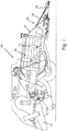
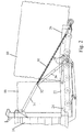
- FIGS 1 and 2 show an agricultural baler 10 comprising a frame 12 which is equipped with a tongue 14 that projects forward to be hitched on to a towing tractor.
- Square bales are formed and tied in a baling chamber 16 in a conventional manner and the bales 18 (see Figure 2 ) are discharged from the rear end of the baling chamber 16 onto a bale chute, generally designated 20.
- the discharge chute 20 is formed in two portions, namely a front portion 22 that is pivoted about an axis 24 to the rear end of the frame 12 and a rear portion 26 that is pivotable relative to the front portion 22 about an axis 28.
- the bale supporting surfaces of both portions 22 and 26 are coplanar and inclined at an angle or approximately 6° to the horizontal. If dropped from a height onto the ground, bales can be damaged and the purpose of the pivoting rear portion 26 is to lower the bales more gently onto the ground.
- bale chute 20 when the weight of a bale 18 rests on the rear portion 26 of the bale chute 20, the latter pivots clockwise, as viewed, to lower its trailing end closer to the ground. The bale 18 slides off the rear portion 26 until its rear end touches the ground while the front end of the bale is still supported by the bale chute. As the baler pulls away from the bale, its front end falls off the bale chute without any risk of the bale toppling.
- the rear portion 26 of the bale chute is supported on each side of the baler by a chain 30 connected to an elbow joint 32 between two arms 34 and 36 that are articulated to one another.
- the two arms 34 and 36 are held in a straight line by the weight of the front section 22 of the bale chute 20 and by the next bale 18 which is formed in the bale chamber 16.
- the rear portion 26 pivots until the chain 30 lies in line with the arm 34.
- Means for weighing a bale may be implemented most simply by providing a transducer to measure the tension in the chain 30 while the rear portion 26 of the bale chute 20 is in the position shown in Figure 2 . In this position, the rear end of the bale 18 is raised from the front portion 22 of the bale chute and substantially all its weight is supported by the rear portion 26. Because the bale is tilted, there is minimal contact between the bale being weighed and the succeeding bale acting to push it off the bale chute 20. The combination of the two will increase the accuracy of the measured signal and thus the value of the weight of the bale.
- the chain tension is therefore a reliable indicator of the weight of the bale and there is ample time to take the required measurement because the bale remains supported in this manner from the time that its centre of gravity has passed the point where its weight is sufficient to pivot the rear portion into the inclined position of Figure 2 until the instant when the rear end of the bale touches the ground. If several measurements are taken, filtering may be used to minimise errors caused by the bale chute being jogged up and down as the baler 10 is towed over uneven ground.
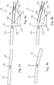
- Figures 3a and 3b show how the known arrangement that has been described by reference to Figures 1 and 2 may be represented schematically.
- Figure 3a corresponds to the position shown in Figure 1 in which the two portions 22 and 26 of the bale chute are in line with one another and
- Figure 3b corresponds to the position shown in Figure 2 .
- Figures 4a and 4b show the preferred embodiment of the invention.
- the portion of the bale chute 22a of Figures 4a and 4b corresponds to the portion 22 in Figures 3a and 3b .
- the tilting axis 128 of the pivot table is mounted on a frame made up of limbs 22b and 22c rigidly connected to the rear portion 22a.
- the axis or tilting point 128 now lies beneath the bale support surface of the rear portion 26.
- the axis 28 is now only used to move the rear portion of the chute into the transport position.
- the weighing table 26b is asymmetrical having a larger surface after the tilting point 128.
- This asymmetrical design has the advantage that the available contact surface, once the centre of gravity of the bale is over the tilting point 128, is sufficiently long to allow a correct measuring. If this distance would be shorter, a correct measuring could also be achieved, if the bale could be significantly slowed down to allow a sufficient time interval in which the bale can be weighed.
- the extra weight of the weighing table 26b after the tilting point 128 will help in tilting the table 26b, even when the centre of gravity of the bale has just passed the tilting point 128, thus freeing the bale sooner from the next bale in the baling chamber 16.
- the rear portion 26 of the bale chute 20 is formed in this embodiment of a pivot frame 26a which, as its name implies, pivots about the axis 128.
- a separate weighing table 26b is supported on the pivot frame 26a by means of two load beams 26c (arranged one on each side of the weighing table).
- the weighing table has an asymmetrical design and in the preferred embodiment the distance before the tilting point 128 is 1 to 3, whereas the distance after the tilting point 128 is 2 to 3.
- Mountings 26d and 26e connect the load beams 26c to the weighing table 26b and the pivot frame 26a in such a manner that the load beams are horizontal in the ideal weighing position as shown in Figure 4b .
- the ideal window in which the bale can be weighed is when the centre of gravity is above the load beams 26c and the bale is isolated on the weighing table.
- the load beams are located near the end of the weighing table 26b. If the load beams 26c would be in the centre of the weighing table, it would not change the range in which the bale is isolated and ready to be weighed. However, the error on the measuring signal will be higher because of the momentum created on the load beams 26c due to the distance between the bale's centre of gravity and the load beams 26c. If the load beams 26c are above the tilting point 128, the error can be as much as 5%.
- the load beams 26c are located such that they are horizontal in the positioning range where the bale can be weighted, thus when the weighing table is within a specific inclination range as will be described further down.
- the weighing table 26 will only pivot when the centre of gravity of the bale slides over a certain toppling point 128. Due to the weight of the bale and the inclination of the table 26, the bale will slide further down the weighing table, thus tilting the table even further until the table hits against stops. The reaction speed of the tilting increases exponential when the distance between the centre of gravity of the bale and the tilting point increases.
- a damper is installed between the chain 30 and the rear portion of pivot frame 26 of the bale chute. It will slow down the movement of the weighing table 26 and will stretch the time window which is needed to accurately measure the weight of the bale.
- the damper will also damp the vibrations which occur when driving the machine over the field.
- a further advantage of this geometry is that accelerations in the fore and aft directions of movement are decoupled from the weighing table and only vertical accelerations will affect the weight measurements indicated by the load beams 26c. These vertical accelerations can be compensated by installing an accelerometer (not shown) in a transverse direction anywhere on the baler. If the baler is driven over an uneven field and the bale is in its weighing position at the moment that the machine drives into a pit, the baler and bale chute will move downwards but due to the inertia, the bale will follow this movement a small fraction later. If the bale hits the weighing table, it will give a wrong indication of the actual weight of the bale.
- the baler If the baler is driven in a pit, the baler will suddenly move downward and this will be detected by the accelerometer. The amplitude of the signal will give an indication on how much the weighing signal needs to be compensated. This correction can be done by software.
- the accelerometer is placed in between the two load beams at the same level as where the forces are measured.
- bale can be used to provide a left and right indication to assist the driver in steering over the centre of the swath.
- Means to measure the inclination such as inclination sensors mounted between the weighing table 26 and the pivot frame 22 provide an indication of when weight measurements can be taken, the weight of the bale being fully supported by the rear portion of the bale chute only in a specific inclination range which, as mentioned earlier, depends on the overall design of the baler such as e.g. the angle of the bale chamber.
- the relative inclination is between 7° and 9°, this corresponding to an inclination to the horizontal of 13° to 15°. It is advantageous for weight measurements only to be taken when the inclination of the pivot frame lies within this specific inclination range.
- the weighing table may be formed of a roller conveyor and it is preferred to fit a friction brake to one of the rollers of the conveyor to prolong the time during which the weight of the bale is supported by the rear portion of the bale chute.
- a friction brake acting on a roller
- a replaceable friction pad or edge may be included in the support surface to rub against one or more side of the bale. The replaceable friction pad may be changed depending on the differences in crop and/or crop conditions.
- the weight sensed by the load beams is monitored during the time that the weighing table is sensed to be inclined in a specific inclination range such as 7° and 9° to the rear portion of the bale chute. Several reading may be taken during this time and processed to eliminate errors caused by vertical accelerations.
- the weight determined by the load beams on the opposite sides of the baler are summed to determine the total weight of each bale. If desired, the difference between the two measurements can be given to the driver to indicate imbalance in the bale, normally resulting from the baler not being properly centred on the swath that is being gathered. This asymmetry indication allows the driver to apply the necessary steering correction.
Landscapes
- Life Sciences & Earth Sciences (AREA)
- Environmental Sciences (AREA)
- Harvester Elements (AREA)
- Loading Or Unloading Of Vehicles (AREA)
- Storage Of Harvested Produce (AREA)
Claims (15)
- Eine Rechteckballenpresse (10) mit einer Ballenkammer (16) und einer Ballenrutsche (20), die an dem Auswurfende der Ballenkammer (16) angeordnet ist, wobei die Ballenrutsche (20) Folgendes umfasst:- einen vorderen Teil (22a, 22b, 22c); und- einen hinteren Teil (26, 26a, 26b, 26c) der an dem vorderen Teil (22a, 22b, 22c) um eine erste horizontale Achse (28) schwenkbar befestigt ist,dadurch gekennzeichnet, dass der hintere Teil (26) Folgendes umfasst:- einen Schwenkrahmen (26a), der um eine zweite Achse (128) verschwenkbar angeordnet ist, die unterhalb der Ebene liegt, auf der der Ballen (18) gleitet, und nach hinten gegenüber der Vorderkante des hinteren Teils (26) versetzt ist, um zwischen einer oberen, einen Ballen tragenden Position und einer abgesenkten, den Ballen auswerfenden Position zu verschwenken, um es jedem Ballen (18) zu ermöglichen, auf dem Boden abgesenkt zu werden, ohne das der Ballen (18) auf seinem Ende kippt, wenn er die Ballenrutsche (120) verlässt; und- einen Wiegetisch (26b), über den der Ballen (18) gleitet, während er von der Ballenrutsche (20) herunter geschoben wird, wobei der Wiegetisch (26) auf dem Schwenkrahmen (26) mit Hilfe von zwei Lastträgern (26c) und Befestigungselementen (26d, 26e) gehaltert ist, die die Lastträger (26c) mit dem Wiegetisch (26b) und dem Schwenkrahmen (26a) verbinden.
- Die Ballenpresse nach Anspruch 1, bei der Einrichtungen zur Messung der Neigung des Schwenkrahmens (26a) gegenüber dem Rest der Ballenrutsche (20) vorgesehen sind, um ein Zeitfenster zu bestimmen, in dem Gewichtsmessungen ausgeführt werden können.
- Eine Ballenpresse nach Anspruch 1 oder 2, bei der die Gewichtsmessungen lediglich dann auszuführen sind, wenn die Neigung des Schwenkrahmens (26a) innerhalb eines vorgegebenen Bereiches liegt.
- Eine Ballenpresse nach Anspruch 3, bei dem der Bereich der Neigung, innerhalb dessen die Gewichtsmessungen ausgeführt werden, um 14° zu der Horizontalen zentriert ist.
- Eine Ballenpresse nach irgendeinem der vorhergehenden Ansprüche, bei der zur Vergrößerung der Verweilzeit des Ballens (18) auf den Wiegetisch (26b) eine Bremse zum Verzögern der Vorwärtsbewegung des Ballens (18) vorgesehen ist, während dieser von dem Wiegetisch (26b) heruntergleitet.
- Eine Ballenpresse nach Anspruch 5, bei dem die Bremse eine Reibungsbremse ist, die auf eine Walze wirkt, die einen Teil des Wiegetisches (26b) bildet.
- Eine Ballenpresse nach Anspruch 5, bei der die Bremse ein Reibelement umfasst, das auf einer oder mehreren Seiten des Ballens (18) reibt, während dieser über den Wiegetisch (26b) gleitet.
- Eine Ballenpresse nach irgendeinem der vorhergehenden Ansprüche, bei der die zum Wiegen eines Ballens (18) während dessen Auflage auf dem Wiegetisch (26b) verwendeten Einrichtungen zwei Lastträger (26c) umfassen, die zwischen dem Wiegetisch (26b) und dem Schwenkrahmen (26a), einer auf jeder Seite des Tisches (26b), angeordnet sind.
- Eine Ballenpresse nach Anspruch 8, bei der die Lastträger (26c) unter einem bestimmten Winkel zu der Auflagefläche des Wiegetisches (26b) drart angeordnet sind, dass sie im Wesentlichen horizontal sind, wenn die Gewichtsmessungen durchgeführt werden.
- Eine Ballenpresse nach Anspruch 9, bei der der bestimmte Winkel der Lastträger ungefähr 8° zu der Auflagefläche des Wiegetisches (26b) ist.
- Eine Ballenpresse nach den Ansprüchen 8 bis 10, bei der Einrichtungen zum Vergleich der von den Lastträgern (26c) auf entgegengesetzten Seiten der Ballenpresse (10) gemessenen Gewichte zur Lieferung einer linken und rechten Anzeige vorgesehen sind, um den Fahrer beim Lenken über den Mittelpunkt des Schwads zu unterstützen.
- Eine Ballenpresse nach irgendeinem der Ansprüche 1 bis 11, bei der Einrichtungen zum Dämpfen der Schwenkbewegung des Schwenkrahmens (26b) vorgesehen sind, wenn der Schwerpunkt des Ballens über dem Schwenkpunkt des Schwenkrahmens (26a) liegt.
- Eine Ballenpresse nach Anspruch 12, bei dem die Einrichtung eine Dämpfungseinrichtung ist, die zwischen dem Schwenkrahmen (26a) und einer Kette (30) angeschlossen ist, wobei die Kette (30) den Schwenkrahmen (26a) mit der Ballenpresse (10) verbindet.
- Eine Ballenpresse nach irgendeinem der vorhergehenden Ansprüche, bei der Einrichtungen auf der Ballenpresse vorgesehen sind, um Vertikalbeschleunigungen zu messen, derart, dass diese Beschleunigungen kompensiert werden können.
- Eine Ballenpresse nach Anspruch 14, bei der die Einrichtungen zur Feststellung der Vertikalbeschleunigung durch einen Beschleunigungsmesser gebildet sind.
Applications Claiming Priority (1)
| Application Number | Priority Date | Filing Date | Title |
|---|---|---|---|
| GB0625240A GB2444914A (en) | 2006-12-19 | 2006-12-19 | Improvements in Agricultural Balers |
Publications (2)
| Publication Number | Publication Date |
|---|---|
| EP1935232A1 EP1935232A1 (de) | 2008-06-25 |
| EP1935232B1 true EP1935232B1 (de) | 2017-05-10 |
Family
ID=37734477
Family Applications (1)
| Application Number | Title | Priority Date | Filing Date |
|---|---|---|---|
| EP07123291.2A Active EP1935232B1 (de) | 2006-12-19 | 2007-12-14 | Verbesserte Vorrichtung zur Ablage von Ballen für eine landwirtschaftliche Ballenpresse |
Country Status (3)
| Country | Link |
|---|---|
| US (1) | US7584696B2 (de) |
| EP (1) | EP1935232B1 (de) |
| GB (1) | GB2444914A (de) |
Families Citing this family (25)
| Publication number | Priority date | Publication date | Assignee | Title |
|---|---|---|---|---|
| GB2449902A (en) * | 2007-06-07 | 2008-12-10 | Cnh Belgium Nv | Weighing apparatus |
| CA2723390C (en) * | 2008-05-07 | 2016-12-13 | Cameron Health, Inc. | Methods and devices for accurately classifying cardiac activity |
| BE1018759A3 (nl) * | 2009-05-19 | 2011-08-02 | Cnh Belgium Nv | Een rechthoekige balenpers met een verbeterde uitwerpgoot. |
| BE1018838A3 (nl) * | 2009-07-29 | 2011-09-06 | Cnh Belgium Nv | Een balenpers met een weegsysteem. |
| WO2011033357A2 (en) * | 2009-09-16 | 2011-03-24 | Agco, Corporation | Bale chute weighing apparatus for crop balers |
| BE1019619A3 (nl) | 2009-09-17 | 2012-09-04 | Cnh Belgium Nv | Een rechthoekige balenpers met een stuureenheid. |
| BE1019181A3 (nl) | 2010-02-12 | 2012-04-03 | Cnh Belgium Nv | Vierkantebalenpers en bijbehorende regelmethode. |
| NL1037742C2 (en) * | 2010-02-23 | 2011-08-24 | Forage Innovations Bv | Wrapper for wrapping bales of crop material. |
| US20120240795A1 (en) * | 2010-12-28 | 2012-09-27 | Agco Corporation | Roller Bale Chute Accumulation |
| US20130218421A1 (en) * | 2012-02-13 | 2013-08-22 | Leland K. Millsap | Semi-automatic tie table control system for a rotatable and tiltable tie table for a mid-size or big bale stack wagon |
| US9439357B2 (en) | 2012-02-21 | 2016-09-13 | Cnh Industrial America Llc | Square balers |
| EP2816889B1 (de) * | 2012-02-23 | 2016-11-16 | CNH Industrial Belgium nv | Multimodales kontrollsystem für rechteckige ballenpresse und entsprechendes verfahren |
| US9664249B2 (en) | 2013-01-11 | 2017-05-30 | Cnh Industrial Canada, Ltd. | System and method of tractor control based on agricultural implement performance |
| BE1021100B1 (nl) | 2013-07-09 | 2016-01-29 | Cnh Industrial Belgium Nv | Balenaflaadmiddelen |
| WO2015014625A1 (en) * | 2013-07-31 | 2015-02-05 | Cnh Industrial Belgium Nv | Method of operating an agricultural baler |
| US9980437B2 (en) | 2014-03-25 | 2018-05-29 | CNH Industrial American LLC | Baling system having a bale position sensor |
| US10918020B2 (en) | 2015-09-30 | 2021-02-16 | Deere & Company | Baler and accumulator control system |
| US10306837B2 (en) | 2016-04-08 | 2019-06-04 | Deere & Company | Bale storage system with damper assembly |
| US10306838B2 (en) | 2016-04-08 | 2019-06-04 | Deere & Company | Bale storage system with damper assembly |
| US10433488B2 (en) | 2016-04-08 | 2019-10-08 | Deere & Company | Bale storage system with damper assembly |
| CN108055913A (zh) * | 2018-01-23 | 2018-05-22 | 江苏沃得农业机械有限公司 | 收割机脱粒后秸秆成堆卸下装置 |
| US11102933B1 (en) * | 2020-04-29 | 2021-08-31 | Deere & Company | Systems and methods for controlling a configuration of a bale chute of a baler |
| CN112005733A (zh) * | 2020-08-17 | 2020-12-01 | 安徽科技学院 | 一种用于自驱式打捆机的成捆与卸捆装置 |
| CN112373097B (zh) * | 2020-10-26 | 2022-07-26 | 永康市凡谷进出口有限公司 | 厨余垃圾污水处理设备及其处理方法 |
| EP4226758B1 (de) * | 2022-02-14 | 2024-11-13 | Agco Corporation | Landwirtschaftliche ballenpresse |
Family Cites Families (13)
| Publication number | Priority date | Publication date | Assignee | Title |
|---|---|---|---|---|
| US2948213A (en) * | 1959-05-12 | 1960-08-09 | Jay George | Scale attachment for balers |
| US4742880A (en) * | 1987-04-15 | 1988-05-10 | Hesston Corporation | Method and apparatus for determining the weight of bales issuing from a crop baler |
| US5384436A (en) * | 1993-06-30 | 1995-01-24 | Pritchard; Gary E. | Apparatus and method for electrically weighing bales in a mobile crop baler |
| DE4436128A1 (de) * | 1994-09-27 | 1996-03-28 | Claas Ohg | Wägeeinrichtung für Ballenpressen |
| US5540144A (en) * | 1995-03-21 | 1996-07-30 | Hay & Forage Industries | Extrusion type square baler having selective bale ejector |
| US5560191A (en) * | 1995-06-05 | 1996-10-01 | Finney; Denzel R. | Jumbo bale rotating table for a hay baler |
| DE29517425U1 (de) | 1995-11-03 | 1996-01-11 | Maschinenfabriken Bernard Krone Gmbh, 48480 Spelle | Ballenpresse |
| US5742010A (en) * | 1996-08-28 | 1998-04-21 | Griffin; Thomas J. | Hay baler scale |
| US5811739A (en) * | 1997-03-28 | 1998-09-22 | Palmore; Donald | Mobile bale weighing device |
| EP0974260B1 (de) | 1998-07-23 | 2003-12-03 | CNH Belgium N.V. | Bewegbare Ballenablagevorrichtung für eine Ballenpresse |
| DE19835163C1 (de) * | 1998-08-04 | 1999-07-22 | Case Harvesting Sys Gmbh | Verfahren und Vorrichtung zur Ermittlung der Gewichtskraft von Ballen |
| DE19835166C2 (de) * | 1998-08-04 | 2000-06-15 | Case Harvesting Sys Gmbh | Verfahren und Vorrichtung zum Feststellen der Preßdichte von Ballen |
| US6033172A (en) * | 1999-02-19 | 2000-03-07 | Maize Corporation | Bale turning apparatus |
-
2006
- 2006-12-19 GB GB0625240A patent/GB2444914A/en not_active Withdrawn
-
2007
- 2007-11-16 US US11/941,620 patent/US7584696B2/en active Active
- 2007-12-14 EP EP07123291.2A patent/EP1935232B1/de active Active
Also Published As
| Publication number | Publication date |
|---|---|
| EP1935232A1 (de) | 2008-06-25 |
| GB2444914A (en) | 2008-06-25 |
| US7584696B2 (en) | 2009-09-08 |
| GB0625240D0 (en) | 2007-01-31 |
| US20080141870A1 (en) | 2008-06-19 |
Similar Documents
| Publication | Publication Date | Title |
|---|---|---|
| EP1935232B1 (de) | Verbesserte Vorrichtung zur Ablage von Ballen für eine landwirtschaftliche Ballenpresse | |
| US7064282B2 (en) | Large round baler with weighing arrangement | |
| EP2533625B1 (de) | Quaderballenpresse und entsprechendes steuerverfahren | |
| US6457295B1 (en) | Round baler | |
| US5384436A (en) | Apparatus and method for electrically weighing bales in a mobile crop baler | |
| US7331168B2 (en) | Baler | |
| EP3567350B1 (de) | Verbesserte strohballengewichtsmessvorrichtung | |
| EP2745675B2 (de) | Wiegen von Rundballen | |
| EP2000785B1 (de) | Wiegevorrichtung | |
| US5742010A (en) | Hay baler scale | |
| US2982201A (en) | Hay balers | |
| EP2458968B1 (de) | Eine ballenpressvorrichtung mit einer wägeeinrichtung | |
| US5811739A (en) | Mobile bale weighing device | |
| US9439357B2 (en) | Square balers | |
| CN115743714A (zh) | 采棉打包一体机的棉包称重系统及方法、农业收获设备 | |
| CZ95594A3 (en) | Mobile bale collector with a suitable baling machine | |
| AU744047B2 (en) | Mass flow rate sensor for sugar cane harvesters | |
| BE1019845A3 (nl) | Een vierkante balenpers met een display dat een indicatie geeft van het gewicht van voltooide balen. | |
| DK177000B1 (da) | Vogn til transport af baller |
Legal Events
| Date | Code | Title | Description |
|---|---|---|---|
| PUAI | Public reference made under article 153(3) epc to a published international application that has entered the european phase |
Free format text: ORIGINAL CODE: 0009012 |
|
| AK | Designated contracting states |
Kind code of ref document: A1 Designated state(s): AT BE BG CH CY CZ DE DK EE ES FI FR GB GR HU IE IS IT LI LT LU LV MC MT NL PL PT RO SE SI SK TR |
|
| AX | Request for extension of the european patent |
Extension state: AL BA HR MK RS |
|
| 17P | Request for examination filed |
Effective date: 20081229 |
|
| AKX | Designation fees paid |
Designated state(s): AT BE BG CH CY CZ DE DK EE ES FI FR GB GR HU IE IS IT LI LT LU LV MC MT NL PL PT RO SE SI SK TR |
|
| 17Q | First examination report despatched |
Effective date: 20090211 |
|
| RAP1 | Party data changed (applicant data changed or rights of an application transferred) |
Owner name: CNH INDUSTRIAL BELGIUM NV |
|
| GRAP | Despatch of communication of intention to grant a patent |
Free format text: ORIGINAL CODE: EPIDOSNIGR1 |
|
| INTG | Intention to grant announced |
Effective date: 20161202 |
|
| RIN1 | Information on inventor provided before grant (corrected) |
Inventor name: DE RYCKE, STEFAN Inventor name: MONTEYNE, NIKLAAS G.C. Inventor name: VANDE RYSE, JOHAN A.E. Inventor name: VERHAEGHE, DIDIER O.M. Inventor name: NAAKTGEBOREN, ADRIANUS Inventor name: VANHERCKE, OLIVIER |
|
| GRAS | Grant fee paid |
Free format text: ORIGINAL CODE: EPIDOSNIGR3 |
|
| GRAA | (expected) grant |
Free format text: ORIGINAL CODE: 0009210 |
|
| AK | Designated contracting states |
Kind code of ref document: B1 Designated state(s): AT BE BG CH CY CZ DE DK EE ES FI FR GB GR HU IE IS IT LI LT LU LV MC MT NL PL PT RO SE SI SK TR |
|
| REG | Reference to a national code |
Ref country code: GB Ref legal event code: FG4D |
|
| REG | Reference to a national code |
Ref country code: AT Ref legal event code: REF Ref document number: 891314 Country of ref document: AT Kind code of ref document: T Effective date: 20170515 Ref country code: CH Ref legal event code: EP |
|
| REG | Reference to a national code |
Ref country code: IE Ref legal event code: FG4D |
|
| REG | Reference to a national code |
Ref country code: DE Ref legal event code: R096 Ref document number: 602007050917 Country of ref document: DE |
|
| REG | Reference to a national code |
Ref country code: NL Ref legal event code: FP |
|
| REG | Reference to a national code |
Ref country code: LT Ref legal event code: MG4D |
|
| REG | Reference to a national code |
Ref country code: FR Ref legal event code: PLFP Year of fee payment: 11 |
|
| REG | Reference to a national code |
Ref country code: AT Ref legal event code: MK05 Ref document number: 891314 Country of ref document: AT Kind code of ref document: T Effective date: 20170510 |
|
| PG25 | Lapsed in a contracting state [announced via postgrant information from national office to epo] |
Ref country code: AT Free format text: LAPSE BECAUSE OF FAILURE TO SUBMIT A TRANSLATION OF THE DESCRIPTION OR TO PAY THE FEE WITHIN THE PRESCRIBED TIME-LIMIT Effective date: 20170510 Ref country code: ES Free format text: LAPSE BECAUSE OF FAILURE TO SUBMIT A TRANSLATION OF THE DESCRIPTION OR TO PAY THE FEE WITHIN THE PRESCRIBED TIME-LIMIT Effective date: 20170510 Ref country code: LT Free format text: LAPSE BECAUSE OF FAILURE TO SUBMIT A TRANSLATION OF THE DESCRIPTION OR TO PAY THE FEE WITHIN THE PRESCRIBED TIME-LIMIT Effective date: 20170510 Ref country code: FI Free format text: LAPSE BECAUSE OF FAILURE TO SUBMIT A TRANSLATION OF THE DESCRIPTION OR TO PAY THE FEE WITHIN THE PRESCRIBED TIME-LIMIT Effective date: 20170510 Ref country code: GR Free format text: LAPSE BECAUSE OF FAILURE TO SUBMIT A TRANSLATION OF THE DESCRIPTION OR TO PAY THE FEE WITHIN THE PRESCRIBED TIME-LIMIT Effective date: 20170811 |
|
| PG25 | Lapsed in a contracting state [announced via postgrant information from national office to epo] |
Ref country code: LV Free format text: LAPSE BECAUSE OF FAILURE TO SUBMIT A TRANSLATION OF THE DESCRIPTION OR TO PAY THE FEE WITHIN THE PRESCRIBED TIME-LIMIT Effective date: 20170510 Ref country code: SE Free format text: LAPSE BECAUSE OF FAILURE TO SUBMIT A TRANSLATION OF THE DESCRIPTION OR TO PAY THE FEE WITHIN THE PRESCRIBED TIME-LIMIT Effective date: 20170510 Ref country code: IS Free format text: LAPSE BECAUSE OF FAILURE TO SUBMIT A TRANSLATION OF THE DESCRIPTION OR TO PAY THE FEE WITHIN THE PRESCRIBED TIME-LIMIT Effective date: 20170910 Ref country code: BG Free format text: LAPSE BECAUSE OF FAILURE TO SUBMIT A TRANSLATION OF THE DESCRIPTION OR TO PAY THE FEE WITHIN THE PRESCRIBED TIME-LIMIT Effective date: 20170810 Ref country code: PL Free format text: LAPSE BECAUSE OF FAILURE TO SUBMIT A TRANSLATION OF THE DESCRIPTION OR TO PAY THE FEE WITHIN THE PRESCRIBED TIME-LIMIT Effective date: 20170510 |
|
| PG25 | Lapsed in a contracting state [announced via postgrant information from national office to epo] |
Ref country code: SK Free format text: LAPSE BECAUSE OF FAILURE TO SUBMIT A TRANSLATION OF THE DESCRIPTION OR TO PAY THE FEE WITHIN THE PRESCRIBED TIME-LIMIT Effective date: 20170510 Ref country code: DK Free format text: LAPSE BECAUSE OF FAILURE TO SUBMIT A TRANSLATION OF THE DESCRIPTION OR TO PAY THE FEE WITHIN THE PRESCRIBED TIME-LIMIT Effective date: 20170510 Ref country code: EE Free format text: LAPSE BECAUSE OF FAILURE TO SUBMIT A TRANSLATION OF THE DESCRIPTION OR TO PAY THE FEE WITHIN THE PRESCRIBED TIME-LIMIT Effective date: 20170510 Ref country code: RO Free format text: LAPSE BECAUSE OF FAILURE TO SUBMIT A TRANSLATION OF THE DESCRIPTION OR TO PAY THE FEE WITHIN THE PRESCRIBED TIME-LIMIT Effective date: 20170510 Ref country code: CZ Free format text: LAPSE BECAUSE OF FAILURE TO SUBMIT A TRANSLATION OF THE DESCRIPTION OR TO PAY THE FEE WITHIN THE PRESCRIBED TIME-LIMIT Effective date: 20170510 |
|
| REG | Reference to a national code |
Ref country code: DE Ref legal event code: R097 Ref document number: 602007050917 Country of ref document: DE |
|
| PG25 | Lapsed in a contracting state [announced via postgrant information from national office to epo] |
Ref country code: IT Free format text: LAPSE BECAUSE OF FAILURE TO SUBMIT A TRANSLATION OF THE DESCRIPTION OR TO PAY THE FEE WITHIN THE PRESCRIBED TIME-LIMIT Effective date: 20170510 |
|
| PLBE | No opposition filed within time limit |
Free format text: ORIGINAL CODE: 0009261 |
|
| STAA | Information on the status of an ep patent application or granted ep patent |
Free format text: STATUS: NO OPPOSITION FILED WITHIN TIME LIMIT |
|
| 26N | No opposition filed |
Effective date: 20180213 |
|
| PG25 | Lapsed in a contracting state [announced via postgrant information from national office to epo] |
Ref country code: SI Free format text: LAPSE BECAUSE OF FAILURE TO SUBMIT A TRANSLATION OF THE DESCRIPTION OR TO PAY THE FEE WITHIN THE PRESCRIBED TIME-LIMIT Effective date: 20170510 |
|
| REG | Reference to a national code |
Ref country code: CH Ref legal event code: PL |
|
| REG | Reference to a national code |
Ref country code: IE Ref legal event code: MM4A |
|
| PG25 | Lapsed in a contracting state [announced via postgrant information from national office to epo] |
Ref country code: LU Free format text: LAPSE BECAUSE OF NON-PAYMENT OF DUE FEES Effective date: 20171214 Ref country code: MT Free format text: LAPSE BECAUSE OF NON-PAYMENT OF DUE FEES Effective date: 20171214 |
|
| REG | Reference to a national code |
Ref country code: FR Ref legal event code: PLFP Year of fee payment: 12 |
|
| PG25 | Lapsed in a contracting state [announced via postgrant information from national office to epo] |
Ref country code: IE Free format text: LAPSE BECAUSE OF NON-PAYMENT OF DUE FEES Effective date: 20171214 |
|
| PG25 | Lapsed in a contracting state [announced via postgrant information from national office to epo] |
Ref country code: LI Free format text: LAPSE BECAUSE OF NON-PAYMENT OF DUE FEES Effective date: 20171231 Ref country code: CH Free format text: LAPSE BECAUSE OF NON-PAYMENT OF DUE FEES Effective date: 20171231 |
|
| PG25 | Lapsed in a contracting state [announced via postgrant information from national office to epo] |
Ref country code: HU Free format text: LAPSE BECAUSE OF FAILURE TO SUBMIT A TRANSLATION OF THE DESCRIPTION OR TO PAY THE FEE WITHIN THE PRESCRIBED TIME-LIMIT; INVALID AB INITIO Effective date: 20071214 Ref country code: MC Free format text: LAPSE BECAUSE OF FAILURE TO SUBMIT A TRANSLATION OF THE DESCRIPTION OR TO PAY THE FEE WITHIN THE PRESCRIBED TIME-LIMIT Effective date: 20170510 |
|
| PG25 | Lapsed in a contracting state [announced via postgrant information from national office to epo] |
Ref country code: CY Free format text: LAPSE BECAUSE OF NON-PAYMENT OF DUE FEES Effective date: 20170510 |
|
| PGFP | Annual fee paid to national office [announced via postgrant information from national office to epo] |
Ref country code: NL Payment date: 20191224 Year of fee payment: 13 |
|
| PG25 | Lapsed in a contracting state [announced via postgrant information from national office to epo] |
Ref country code: TR Free format text: LAPSE BECAUSE OF FAILURE TO SUBMIT A TRANSLATION OF THE DESCRIPTION OR TO PAY THE FEE WITHIN THE PRESCRIBED TIME-LIMIT Effective date: 20170510 |
|
| PGFP | Annual fee paid to national office [announced via postgrant information from national office to epo] |
Ref country code: GB Payment date: 20191220 Year of fee payment: 13 |
|
| PG25 | Lapsed in a contracting state [announced via postgrant information from national office to epo] |
Ref country code: PT Free format text: LAPSE BECAUSE OF FAILURE TO SUBMIT A TRANSLATION OF THE DESCRIPTION OR TO PAY THE FEE WITHIN THE PRESCRIBED TIME-LIMIT Effective date: 20170510 |
|
| REG | Reference to a national code |
Ref country code: DE Ref legal event code: R082 Ref document number: 602007050917 Country of ref document: DE Representative=s name: MEISSNER BOLTE PATENTANWAELTE RECHTSANWAELTE P, DE |
|
| REG | Reference to a national code |
Ref country code: DE Ref legal event code: R084 Ref document number: 602007050917 Country of ref document: DE |
|
| PGFP | Annual fee paid to national office [announced via postgrant information from national office to epo] |
Ref country code: BE Payment date: 20201223 Year of fee payment: 14 |
|
| REG | Reference to a national code |
Ref country code: NL Ref legal event code: MM Effective date: 20210101 |
|
| GBPC | Gb: european patent ceased through non-payment of renewal fee |
Effective date: 20201214 |
|
| PG25 | Lapsed in a contracting state [announced via postgrant information from national office to epo] |
Ref country code: NL Free format text: LAPSE BECAUSE OF NON-PAYMENT OF DUE FEES Effective date: 20210101 |
|
| PG25 | Lapsed in a contracting state [announced via postgrant information from national office to epo] |
Ref country code: GB Free format text: LAPSE BECAUSE OF NON-PAYMENT OF DUE FEES Effective date: 20201214 |
|
| REG | Reference to a national code |
Ref country code: BE Ref legal event code: MM Effective date: 20211231 |
|
| PG25 | Lapsed in a contracting state [announced via postgrant information from national office to epo] |
Ref country code: BE Free format text: LAPSE BECAUSE OF NON-PAYMENT OF DUE FEES Effective date: 20211231 |
|
| PGFP | Annual fee paid to national office [announced via postgrant information from national office to epo] |
Ref country code: FR Payment date: 20251223 Year of fee payment: 19 |
|
| PGFP | Annual fee paid to national office [announced via postgrant information from national office to epo] |
Ref country code: DE Payment date: 20251229 Year of fee payment: 19 |