EP2458968B1 - Eine ballenpressvorrichtung mit einer wägeeinrichtung - Google Patents
Eine ballenpressvorrichtung mit einer wägeeinrichtung Download PDFInfo
- Publication number
- EP2458968B1 EP2458968B1 EP10737532.1A EP10737532A EP2458968B1 EP 2458968 B1 EP2458968 B1 EP 2458968B1 EP 10737532 A EP10737532 A EP 10737532A EP 2458968 B1 EP2458968 B1 EP 2458968B1
- Authority
- EP
- European Patent Office
- Prior art keywords
- bale
- weighing
- baler
- timespan
- brake
- Prior art date
- Legal status (The legal status is an assumption and is not a legal conclusion. Google has not performed a legal analysis and makes no representation as to the accuracy of the status listed.)
- Active
Links
Images


Classifications
-
- A—HUMAN NECESSITIES
- A01—AGRICULTURE; FORESTRY; ANIMAL HUSBANDRY; HUNTING; TRAPPING; FISHING
- A01F—PROCESSING OF HARVESTED PRODUCE; HAY OR STRAW PRESSES; DEVICES FOR STORING AGRICULTURAL OR HORTICULTURAL PRODUCE
- A01F15/00—Baling presses for straw, hay or the like
- A01F15/08—Details
- A01F15/0875—Discharge devices
- A01F2015/0891—Weighing the finished bale before falling to ground
Definitions
- the present invention is related to agricultural square balers, used for picking up crop material such as hay or straw from the field and forming it into rectangular bales.
- the invention is in particular related to a baler provided with a weighing system equipped with a brake for slowing down the movement of bales before the bales are ejected from the baler.
- Agricultural square balers gather crop material into a baling chamber where the material is compressed to parallelepiped packages by a reciprocating plunger.
- the finished packages are tied to form the bales, which proceed to be transported on a guide or slide at the exit of the baler, the so-called bale chute, from which they are lowered to the ground.
- the bale chute in prior art systems is usually provided with a tilting mechanism to avoid damaging the bales by lowering them gently to the ground. Examples of known balers of this type are described in EP-A-0974260 and EP-A-1935232 . In some balers the bales are also weighed before they are discharged.
- the bale chute has a rear portion that is pivotable around an axis situated below the bale support surface.
- the rear portion is further provided with a weighing table supported by load beams configured to produce a weight measurement signal.
- the baler of EP-A-1935232 may be further provided with a brake to slow down the bales when they are on the weighing table.
- a brake may be a friction brake arranged on a roller when the weighing table is formed of a roller conveyor, or a replaceable friction pad or edge included in the support surface.
- brake systems are up to now provided as mechanical brakes which are activated manually by the operator.
- the braking action is not always necessary nor can it be adapted to specific conditions in terms of the terrain and the crop.
- the bales tend to move under influence of friction and gravity once the centre of gravity of the bale moves past this pivot axis.
- This movement of the bales is rather uncontrolled and is influenced by local conditions of the crop, the weather and the terrain.
- This uncontrolled movement leads to random errors when considering the weight measurement signal, which are difficult to compensate in a systematic way.
- the present invention aims to improve a baler with a weighing means in order to improve the precision of the weighing means.
- the present invention is related to a square baler and to a method as described in the appended claims.
- a square baler having a baling chamber with a reciprocating plunger and a bale chute arranged at the discharge end of the baling chamber, the bale chute comprising:
- the rear portion further comprising a brake for changing the speed of a bale moving along the rear portion, characterized in that the brake is configured to exert an adjustable braking force, and in that the baler further comprises:
- the brake is configured to produce a continuously or step-wise variable braking force.
- the means for producing a parameter may comprise a microprocessor, configured to receive electronic signals produced by the weighing means, e.g. load beams, and further configured to calculate the parameter(s), e.g. t x , on the basis of the electronic signals.
- a microprocessor configured to receive electronic signals produced by the weighing means, e.g. load beams, and further configured to calculate the parameter(s), e.g. t x , on the basis of the electronic signals.
- the means for producing a parameter may comprise one or more inclination sensors configured to measure the inclination of the pivotable frame and a processor configured to calculate the parameter on the basis of signals produced by the one or more inclination sensor(s).
- a method for weighing bales from a square baler characterised in that the method comprises the steps of:
- FIGS 1 and 2 show a baler 10 according to the invention.
- the main structural components correspond to the baler described in EP1935232 , and comprise a baler frame 12 which is preferably configured to be hitched on to a towing tractor (not shown).
- Square bales are formed by a reciprocating plunger in a baling chamber 16, the bales are then tied and discharged from the rear end of the baling chamber onto the bale chute 20.
- the bale chute is formed of two portions : front portion 22 and rear portion 26.
- the front portion 22 comprises a first portion 22a that is pivotally attached to the baler frame 12 and a second portion that forms a frame made up of vertical plates 22b and a horizontal plate 22c.
- the second portion 22b, 22c is pivotally attached to the first portion 22a by means of an axis 28 that is only used to move the rear portion of the chute into the transport position as described more in detail in EP1935232 .
- the rear portion 26 comprises a pivot frame 26a, which pivots about an axis 128 situated below the support surface of the front portion 22a and rearwards from the leading edge of the rear portion 26, and a weighing table 26b, which is supported on the pivot frame 26a by means of load beams 26c.
- the position of the pivot axis 128 provides a clear separation of the bale once the weighing table 26b pivots in the bale discharging position, so that the bale may be weighed during this suitable weighing timespan.
- the weighing table is formed of a roller conveyor as more clearly visible in Figure 2 .
- one of the rollers preferably the last roll 30 is provided with a braking device mounted on the roller's axis, and configured to influence the roller's rotational speed by the braking force.
- the brake 103 may be a magnetic brake of a known type, such as a flange mounted brake from Warner Electric. Other known configurations are possible such as for example a hydraulic disc or drum brake.
- the brakes that are usable in the invention have a brake force which is adjustable on the basis of a control signal. This means that the brake may be activated, or deactivated and its resulting braking force can be changed when the relevant control signal is transmitted to the brake. Preferably, a change in the brake force is controllable in a continuous or step-wise fashion.
- the baler comprises a control means for producing such a control signal. This may be any type of electronic controller unit known in the art.
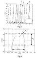
- FIG 3 shows a record of weighing data as a function of time, when using a baler according to the invention and performing the method according to the invention.
- the circles show the actual weight of the bales, while the stars indicate the weight derived from the load beam signals. It can be seen that the two values do not always correspond.
- W p represents the peak of the measured signal, corresponding to the measured weight value (in kg).
- the time interval t x is determined, between the point where the measured weight reaches W p -W x immediately before W p is reached and the point where the same weight W p -W x is reached, immediately after the peak weight W p has been reached.
- W x is a suitable threshold weight and is set to 10kg in the examples shown in Figures 4 , 5 and 6 , but could be chosen to be a different weight or as a certain percentage of W p .
- the interval t x is an indication of the timespan during which the bale is in optimal weighing condition.
- Figure 4 shows the most desirable situation, in which t x equals approximately 1.5s, which corresponds approximately to the period of the plunger movement of the baler (42cycles/minute).
- the measured weight corresponds well to the actual weight of the bale.
- the bale has moved at a higher speed along the weighing table, leading to a t x interval of around 0.5s. This may be due to the fact that the baler moves along a slope, for example.
- the weight signal has not been processed fast enough to be able to approximate the actual weight, and a non-negligable error is made.
- a measurement is shown where a bale spends too much time on the weighing table. The oscillation of the weight signal may be due to bumps in the terrain, causing the bale to jump up and down on the weighing table or due to the influence of the next bale coming out of the baling chamber 16. The result is that the peak weight is an overestimation of the actual weight.
- the plunger period is taken as the desired value for t x , which is thus used as a control parameter to control the brake.
- t x is determined, and the braking power is adjusted on the basis of this parameter. For example, if t x is lower than 1.5s, the braking power is increased, and if t x is higher than 1.5s, the braking power is decreased.
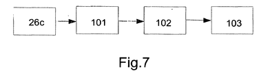
- This is shown schematically in the control cycle depicted in Figure 7 , and comprising the load beams 26c, a processing unit 101 where the measured weight signals are processed to produce the t x value, and a control unit 102 to control the brake 103 on the basis of t x .
- This cycle defines the method according to this embodiment of the invention, the method comprising the steps of :
- the control of the brake may be based on other parameters than t x .
- inclination sensors may be present to measure the inclination of the weighing table 26b. As described in EP-A-1935232 , these inclination sensors may be used to determine the time interval t i during which the weighing table is within a predefined inclination range, being the optimum weighing range, for example 14 degrees around the horizontal. The time interval t i may then be used in the same way as t x described above, as the basis for controlling the braking force.
- the brake can be deactivated completely after each weight measurement and re-activated before the next measurement. This can be useful because the braking power may have a negative effect on the bale discharge outside the actual measurement period. For example, a given number of seconds after the t x interval or after the t i interval, the brake is deactivated, and re-activated when a first inclination of the weighing table is detected by the inclination sensor, or when the weight measurement signal passes a certain minimum weight indicating that a bale is present on the weighing table.
- each determination of t x or t i is used as a basis for adjusting the brake during the next weight measurement.
- the brake may be controlled within each measurement cycle, to influence the speed of the bale as it is weighed. This may for example be done by measuring the slope of each rising weight measurement peak, and adjusting the braking power on the basis of this slope.
- the braking force is controlled on the basis of the inclination of the terrain on which the baler is moving. It is known in the art to apply detecting means on balers to detect this inclination. The signal indicative of this inclination may be used as an input for controlling the braking force, so that when the baler moves (i.e. is towed) downhill, a lower braking force is applied and when the baler moves uphill, a higher braking force is applied.
- a means may be present to input a parameter indicative of the type of crop that is being gathered by the baler.
- the operator may for example enter such a parameter before the baling starts.
- the control means is then programmed to apply a braking force in accordance with the type of crop: for example crop that has a higher density may receive a higher braking force.
- the invention is applicable to any type of brake system, not only to a brake mounted on a roll of a rolling conveyor.
- the same control method can be applied on a movable friction plate or pad, configured to apply friction on one or more surfaces of a bale, to thereby influence the speed of the bale along the bale chute.
Landscapes
- Life Sciences & Earth Sciences (AREA)
- Environmental Sciences (AREA)
- Harvester Elements (AREA)
- Auxiliary Devices For And Details Of Packaging Control (AREA)
Claims (15)
- Rechteckballenpresse (10) mit einer Ballenpresskammer (16) mit einem sich hin- und herbewegenden Presskolben und einer Ballenrutsche (20), die an dem Auswurfende der Ballenpresskammer (16) angeordnet ist, wobei die Ballenrutsche (20) Folgendes umfasst:- einen vorderen Teil (22, 22a, 22b, 22c);- einen hinteren Teil (26, 26a, 26b, 26c), der an dem vorderen Teil (22, 22a, 22b, 22c) um eine horizontale Achse (128) für eine Schwenkbewegung zwischen einer oberen Ballenhalte-Position und einer unteren Ballenauswurf-Position schwenkbar befestigt ist;- wobei die horizontale Achse (128) unterhalb der Ebene liegt, auf der der Ballen gleitet, und gegenüber einer Vorderkante des hinteren Teils (26) nach hinten versetzt ist;- wobei der hintere Teil (26) weiterhin Einrichtungen zum Wiegen eines Ballens während einer Wäge-Zeitspanne umfasst, wenn der hintere Teil (26) in die Ballenauswurf-Position verschwenkt ist; und- wobei der hintere Teil (26) weiterhin eine Bremse (103) zum Ändern der Geschwindigkeit eines Ballens umfasst, der sich entlang des hinteren Teils (26) bewegt,dadurch gekennzeichnet, dass die Bremse (103) zum Ausüben einer einstellbaren Bremskraft konfiguriert ist, und dass die Ballenpresse weiter Folgendes umfasst:- Einrichtungen (26c, 101) zur Erzeugung oder zum Empfang von einem oder mehreren Parametern, die die Wäge-Zeitspanne anzeigen;- eine Steuereinrichtung (102), die zur Einstellung der Bremskraft auf der Grundlage des einen oder mehrerer Parameter konfiguriert ist.
- Ballenpresse nach Anspruch 1, dadurch gekennzeichnet, dass der hintere Teil (26) einen Rollen-Förderer umfasst, und dass die Bremse (103) auf der Achse von zumindest einer der Rollen (30) des Rollen-Förderers befestigt und so konfiguriert ist, dass sie die Drehgeschwindigkeit der zumindest einen Rolle beeinflusst.
- Ballenpresse nach Anspruch 1, dadurch gekennzeichnet, dass die Bremse (103) eine oder mehrere bewegliche Bremsplatten oder Bremsklötze umfasst, die zur Ausübung einer Reibung auf eine oder mehrere Oberflächen eines Ballens konfiguriert sind.
- Ballenpresse nach einem der vorhergehenden Ansprüche, dadurch gekennzeichnet, dass die Einrichtungen zum Wiegen eines Ballens Lastträger (26c) umfassen, und dass der hintere Teil (26) Folgendes umfasst:- einen Schwenkrahmen (26a), der um die horizontale Achse (128) verschwenkbar ist; und- einen getrennten Wägetisch (26b), der auf dem Schwenkrahmen (26a) mit Hilfe von Befestigungen gehaltert ist, die die Lastträger (26c) umfassen.
- Ballenpresse nach Anspruch 4, dadurch gekennzeichnet, dass Einrichtungen zur Messung der Neigung des Schwenkrahmens (26a) gegenüber dem Rest der Ballenrutsche (20) vorgesehen sind, und dass diese Neigung einen Parameter erzeugt, der die Wäge-Zeitspanne anzeigt.
- Ballenpresse nach einem der vorhergehenden Ansprüche, dadurch gekennzeichnet, dass das von den Einrichtungen zum Wiegen eines Ballens gemessene Gewicht einen Parameter erzeugt, der die Wäge-Zeitspanne anzeigt.
- Ballenpresse nach einem der vorhergehenden Ansprüche, dadurch gekennzeichnet, dass sie Einrichtungen zur Messung der Neigung der Ballenpresse bezüglich der Horizontalen umfasst, und wobei die Neigung einen Parameter erzeugt, der die Wäge-Zeitspanne anzeigt.
- Ballenpresse nach einem der vorhergehenden Ansprüche, dadurch gekennzeichnet, dass sie eine Einrichtung zum Empfang eines Parameters umfasst, der den Typ des Erntematerials anzeigt, der von der Ballenpresse gesammelt wird, und wobei dieser Parameter einen Parameter erzeugt, der die Wäge-Zeitspanne anzeigt.
- Verfahren zum Wiegen von Ballen von einer Rechteckballenpresse nach einem der vorhergehenden Ansprüche, dadurch gekennzeichnet, dass das Verfahren die folgenden Schritte umfasst:- Erzeugen eines Ballens in der Rechteckballenpresse (10);- Bewegen des Ballens auf die Ballenrutsche (20);- Messen des Gewichtes des Ballens;- Erzeugen oder Empfangen von einem oder mehreren Parametern, die die Wäge-Zeitspanne anzeigen;- Einstellen der Bremskraft der Bremse (103) auf der Grundlage des einen oder mehrerer Parameter.
- Verfahren nach Anspruch 9, dadurch gekennzeichnet, dass zumindest einer der Parameter, der die Wäge-Zeitspanne anzeigt, durch Folgendes erzeugt wird:- Bestimmen der Spitzen-Gewichts-Messung Wp aus der Gewichts-Messung des Ballens- Bestimmen, aus der Gewichts-Messung des Ballens, des Zeitintervalls tx zwischen dem Zeitpunkt, zu dem das gemessene Gewicht gleich Wp-Wx unmittelbar vor der Spitzen-Gewichts-Messung Wp ist, und dem Zeitpunkt, zu dem das gemessene Gewicht wieder gleich Wp-Wx unmittelbar nach der Spitzen-Gewichts-Messung Wp ist, wobei Wx ein geeignetes Schwellenwert-Gewicht ist.
- Verfahren nach Anspruch 9, dadurch gekennzeichnet, dass zumindest einer der Parameter, der die Wäge-Zeitspanne anzeigt, dadurch erzeugt wird, dass aus der Gewichtsmessung des Ballens die Steigung der gemessenen Gewichts-Kurve bestimmt wird, während diese in Richtung auf die Spitzen-Gewichts-Messung Wp ansteigt.
- Verfahren nach Anspruch 9 unter Rückbeziehung auf Anspruch 4 und irgendeinem hiervon abhängigen Anspruch, dadurch gekennzeichnet, dass zumindest einer der Parameter, der die Wäge-Zeitspanne anzeigt, dadurch erzeugt wird, dass aus der Messung der Neigung des Wäge-Tisches (26b) das Zeitintervall ti bestimmt wird, während der die Neigung des Wäge-Tische (26b) in einem vorgegebenen Bereich liegt.
- Verfahren nach einem der Ansprüche 9 bis 12, dadurch gekennzeichnet, dass die Bremskraft vergrößert wird, wenn die Wäge-Zeitspanne kleiner als die Periode des sich hin- und herbewegenden Presskolbens ist, und die Bremskraft verkleinert wird, wenn die Wäge-Zeitspanne größer als die Periode des hin- und herbeweglichen Presskolbens ist.
- Verfahren nach einem der Ansprüche 9 bis 13, dadurch gekennzeichnet, dass die Bremse (103) während eines Zeitintervalls deaktiviert wird, das nach dem Wiegen eines Ballens beginnt und vor dem Wiegen eines nächsten Ballens endet.
- Verfahren nach einem der Ansprüche 9 bis 14, dadurch gekennzeichnet, dass zumindest einer der Parameter, der die Wäge-Zeitspanne anzeigt, durch einen Parameter, der die Neigung des Geländes anzeigt, auf dem sich die Ballenpresse bewegt, und/oder den Typ des Erntematerials bestimmt iist, das von der Ballenpresse aufgesammelt wird.
Applications Claiming Priority (2)
| Application Number | Priority Date | Filing Date | Title |
|---|---|---|---|
| BE2009/0460A BE1018838A3 (nl) | 2009-07-29 | 2009-07-29 | Een balenpers met een weegsysteem. |
| PCT/EP2010/060437 WO2011012488A1 (en) | 2009-07-29 | 2010-07-19 | A baler with a weighing system |
Publications (2)
| Publication Number | Publication Date |
|---|---|
| EP2458968A1 EP2458968A1 (de) | 2012-06-06 |
| EP2458968B1 true EP2458968B1 (de) | 2013-05-15 |
Family
ID=41785793
Family Applications (1)
| Application Number | Title | Priority Date | Filing Date |
|---|---|---|---|
| EP10737532.1A Active EP2458968B1 (de) | 2009-07-29 | 2010-07-19 | Eine ballenpressvorrichtung mit einer wägeeinrichtung |
Country Status (5)
| Country | Link |
|---|---|
| US (1) | US8635950B2 (de) |
| EP (1) | EP2458968B1 (de) |
| CN (1) | CN102413678B (de) |
| BE (1) | BE1018838A3 (de) |
| WO (1) | WO2011012488A1 (de) |
Families Citing this family (4)
| Publication number | Priority date | Publication date | Assignee | Title |
|---|---|---|---|---|
| BE1019181A3 (nl) | 2010-02-12 | 2012-04-03 | Cnh Belgium Nv | Vierkantebalenpers en bijbehorende regelmethode. |
| DE102012110417A1 (de) * | 2012-10-31 | 2014-04-30 | Ingo Dreher | Verfahren und Vorrichtung zur Kompression von langstängeligem Pflanzengut |
| CN110381728B (zh) * | 2017-03-08 | 2022-09-30 | 爱科公司 | 用于将识别标签捆绑到农作物材料捆包的捆包识别组件 |
| CN115553134B (zh) * | 2022-12-02 | 2023-04-07 | 新乡市花溪科技股份有限公司 | 一种大型打捆机精准称量计数反馈系统 |
Family Cites Families (16)
| Publication number | Priority date | Publication date | Assignee | Title |
|---|---|---|---|---|
| US3126069A (en) * | 1964-03-24 | shepley | ||
| US4742880A (en) * | 1987-04-15 | 1988-05-10 | Hesston Corporation | Method and apparatus for determining the weight of bales issuing from a crop baler |
| US5384436A (en) * | 1993-06-30 | 1995-01-24 | Pritchard; Gary E. | Apparatus and method for electrically weighing bales in a mobile crop baler |
| DE4436128A1 (de) * | 1994-09-27 | 1996-03-28 | Claas Ohg | Wägeeinrichtung für Ballenpressen |
| DE4438222B4 (de) * | 1994-10-26 | 2008-02-14 | Knorr-Bremse Systeme für Nutzfahrzeuge GmbH | Verfahren und Vorrichtung zur Steuerung bzw. Regelung der Bremsanlage eines Fahrzeugs |
| US5742010A (en) * | 1996-08-28 | 1998-04-21 | Griffin; Thomas J. | Hay baler scale |
| EP0974260B1 (de) | 1998-07-23 | 2003-12-03 | CNH Belgium N.V. | Bewegbare Ballenablagevorrichtung für eine Ballenpresse |
| GB2339719A (en) * | 1998-07-23 | 2000-02-09 | Ford New Holland Nv | Bale discharge means for a rectangular baler |
| DE19835163C1 (de) * | 1998-08-04 | 1999-07-22 | Case Harvesting Sys Gmbh | Verfahren und Vorrichtung zur Ermittlung der Gewichtskraft von Ballen |
| ITMI20041604A1 (it) * | 2004-08-04 | 2004-11-04 | Ptm S R L | Rotopressa per il confezionamento in balle di prodotti agricoli |
| GB2444914A (en) * | 2006-12-19 | 2008-06-25 | Cnh Belgium Nv | Improvements in Agricultural Balers |
| KR100761037B1 (ko) * | 2007-03-29 | 2007-09-21 | 라인호(주) | 적재중량에 따라서 제동력이 조절되는 레일 트랜스포터 |
| CN201023677Y (zh) * | 2007-05-08 | 2008-02-20 | 沈红庆 | 新型半自动捆包机 |
| GB2449902A (en) * | 2007-06-07 | 2008-12-10 | Cnh Belgium Nv | Weighing apparatus |
| BE1019619A3 (nl) * | 2009-09-17 | 2012-09-04 | Cnh Belgium Nv | Een rechthoekige balenpers met een stuureenheid. |
| US20120240795A1 (en) * | 2010-12-28 | 2012-09-27 | Agco Corporation | Roller Bale Chute Accumulation |
-
2009
- 2009-07-29 BE BE2009/0460A patent/BE1018838A3/nl not_active IP Right Cessation
-
2010
- 2010-07-19 EP EP10737532.1A patent/EP2458968B1/de active Active
- 2010-07-19 US US13/387,346 patent/US8635950B2/en not_active Expired - Fee Related
- 2010-07-19 CN CN201080018963.4A patent/CN102413678B/zh active Active
- 2010-07-19 WO PCT/EP2010/060437 patent/WO2011012488A1/en not_active Ceased
Also Published As
| Publication number | Publication date |
|---|---|
| WO2011012488A1 (en) | 2011-02-03 |
| CN102413678B (zh) | 2014-12-10 |
| EP2458968A1 (de) | 2012-06-06 |
| US8635950B2 (en) | 2014-01-28 |
| BE1018838A3 (nl) | 2011-09-06 |
| CN102413678A (zh) | 2012-04-11 |
| US20120192730A1 (en) | 2012-08-02 |
Similar Documents
| Publication | Publication Date | Title |
|---|---|---|
| EP1935232B1 (de) | Verbesserte Vorrichtung zur Ablage von Ballen für eine landwirtschaftliche Ballenpresse | |
| BE1019181A3 (nl) | Vierkantebalenpers en bijbehorende regelmethode. | |
| US9854744B2 (en) | Adjusting bale density setting based on bale weight and/or moisture | |
| BE1019619A3 (nl) | Een rechthoekige balenpers met een stuureenheid. | |
| EP2458968B1 (de) | Eine ballenpressvorrichtung mit einer wägeeinrichtung | |
| EP2745675B2 (de) | Wiegen von Rundballen | |
| RU2487319C2 (ru) | Устройство измерения для определения массового расхода убираемых культур | |
| US7064282B2 (en) | Large round baler with weighing arrangement | |
| EP3567350B1 (de) | Verbesserte strohballengewichtsmessvorrichtung | |
| EP3315016B1 (de) | Rundballenpresse und verfahren zur erstellung einer ertragskarte für solch eine rundballenpresse | |
| US6248963B1 (en) | Bale-density measuring system for baler | |
| EP2816889B1 (de) | Multimodales kontrollsystem für rechteckige ballenpresse und entsprechendes verfahren | |
| US6232565B1 (en) | Bale-weighing system for mobile baling press | |
| EP3461324B1 (de) | Verfahren zur steuerung der ballengrösse basierend auf dem ballengewicht | |
| NL2010169C2 (en) | Wrapper and method for wrapping and discharging round bales. | |
| US9439357B2 (en) | Square balers | |
| BE1019827A3 (nl) | Multi-mode controle systeem voor rechthoekige balenpers en gerelateerde methode. | |
| RU2459906C2 (ru) | Способ и устройство для измерения силы сопротивления сдвигу слоев в сыпучем теле | |
| NL2010688C2 (nl) | Landbouwoogstmachine. | |
| KR102936573B1 (ko) | 농작물 수확량 모니터링 시스템 | |
| BE1019845A3 (nl) | Een vierkante balenpers met een display dat een indicatie geeft van het gewicht van voltooide balen. |
Legal Events
| Date | Code | Title | Description |
|---|---|---|---|
| PUAI | Public reference made under article 153(3) epc to a published international application that has entered the european phase |
Free format text: ORIGINAL CODE: 0009012 |
|
| 17P | Request for examination filed |
Effective date: 20120229 |
|
| AK | Designated contracting states |
Kind code of ref document: A1 Designated state(s): AL AT BE BG CH CY CZ DE DK EE ES FI FR GB GR HR HU IE IS IT LI LT LU LV MC MK MT NL NO PL PT RO SE SI SK SM TR |
|
| DAX | Request for extension of the european patent (deleted) | ||
| GRAP | Despatch of communication of intention to grant a patent |
Free format text: ORIGINAL CODE: EPIDOSNIGR1 |
|
| GRAS | Grant fee paid |
Free format text: ORIGINAL CODE: EPIDOSNIGR3 |
|
| GRAA | (expected) grant |
Free format text: ORIGINAL CODE: 0009210 |
|
| AK | Designated contracting states |
Kind code of ref document: B1 Designated state(s): AL AT BE BG CH CY CZ DE DK EE ES FI FR GB GR HR HU IE IS IT LI LT LU LV MC MK MT NL NO PL PT RO SE SI SK SM TR |
|
| REG | Reference to a national code |
Ref country code: CH Ref legal event code: EP Ref country code: GB Ref legal event code: FG4D |
|
| REG | Reference to a national code |
Ref country code: AT Ref legal event code: REF Ref document number: 611627 Country of ref document: AT Kind code of ref document: T Effective date: 20130615 |
|
| REG | Reference to a national code |
Ref country code: IE Ref legal event code: FG4D |
|
| REG | Reference to a national code |
Ref country code: DE Ref legal event code: R096 Ref document number: 602010007149 Country of ref document: DE Effective date: 20130711 |
|
| REG | Reference to a national code |
Ref country code: NL Ref legal event code: T3 |
|
| REG | Reference to a national code |
Ref country code: AT Ref legal event code: MK05 Ref document number: 611627 Country of ref document: AT Kind code of ref document: T Effective date: 20130515 |
|
| REG | Reference to a national code |
Ref country code: LT Ref legal event code: MG4D |
|
| PG25 | Lapsed in a contracting state [announced via postgrant information from national office to epo] |
Ref country code: NO Free format text: LAPSE BECAUSE OF FAILURE TO SUBMIT A TRANSLATION OF THE DESCRIPTION OR TO PAY THE FEE WITHIN THE PRESCRIBED TIME-LIMIT Effective date: 20130815 Ref country code: SE Free format text: LAPSE BECAUSE OF FAILURE TO SUBMIT A TRANSLATION OF THE DESCRIPTION OR TO PAY THE FEE WITHIN THE PRESCRIBED TIME-LIMIT Effective date: 20130515 Ref country code: GR Free format text: LAPSE BECAUSE OF FAILURE TO SUBMIT A TRANSLATION OF THE DESCRIPTION OR TO PAY THE FEE WITHIN THE PRESCRIBED TIME-LIMIT Effective date: 20130816 Ref country code: FI Free format text: LAPSE BECAUSE OF FAILURE TO SUBMIT A TRANSLATION OF THE DESCRIPTION OR TO PAY THE FEE WITHIN THE PRESCRIBED TIME-LIMIT Effective date: 20130515 Ref country code: PT Free format text: LAPSE BECAUSE OF FAILURE TO SUBMIT A TRANSLATION OF THE DESCRIPTION OR TO PAY THE FEE WITHIN THE PRESCRIBED TIME-LIMIT Effective date: 20130916 Ref country code: AT Free format text: LAPSE BECAUSE OF FAILURE TO SUBMIT A TRANSLATION OF THE DESCRIPTION OR TO PAY THE FEE WITHIN THE PRESCRIBED TIME-LIMIT Effective date: 20130515 Ref country code: IS Free format text: LAPSE BECAUSE OF FAILURE TO SUBMIT A TRANSLATION OF THE DESCRIPTION OR TO PAY THE FEE WITHIN THE PRESCRIBED TIME-LIMIT Effective date: 20130915 Ref country code: SI Free format text: LAPSE BECAUSE OF FAILURE TO SUBMIT A TRANSLATION OF THE DESCRIPTION OR TO PAY THE FEE WITHIN THE PRESCRIBED TIME-LIMIT Effective date: 20130515 Ref country code: ES Free format text: LAPSE BECAUSE OF FAILURE TO SUBMIT A TRANSLATION OF THE DESCRIPTION OR TO PAY THE FEE WITHIN THE PRESCRIBED TIME-LIMIT Effective date: 20130826 Ref country code: LT Free format text: LAPSE BECAUSE OF FAILURE TO SUBMIT A TRANSLATION OF THE DESCRIPTION OR TO PAY THE FEE WITHIN THE PRESCRIBED TIME-LIMIT Effective date: 20130515 |
|
| PG25 | Lapsed in a contracting state [announced via postgrant information from national office to epo] |
Ref country code: PL Free format text: LAPSE BECAUSE OF FAILURE TO SUBMIT A TRANSLATION OF THE DESCRIPTION OR TO PAY THE FEE WITHIN THE PRESCRIBED TIME-LIMIT Effective date: 20130515 Ref country code: HR Free format text: LAPSE BECAUSE OF FAILURE TO SUBMIT A TRANSLATION OF THE DESCRIPTION OR TO PAY THE FEE WITHIN THE PRESCRIBED TIME-LIMIT Effective date: 20130515 Ref country code: BG Free format text: LAPSE BECAUSE OF FAILURE TO SUBMIT A TRANSLATION OF THE DESCRIPTION OR TO PAY THE FEE WITHIN THE PRESCRIBED TIME-LIMIT Effective date: 20130815 |
|
| PG25 | Lapsed in a contracting state [announced via postgrant information from national office to epo] |
Ref country code: LV Free format text: LAPSE BECAUSE OF FAILURE TO SUBMIT A TRANSLATION OF THE DESCRIPTION OR TO PAY THE FEE WITHIN THE PRESCRIBED TIME-LIMIT Effective date: 20130515 |
|
| PG25 | Lapsed in a contracting state [announced via postgrant information from national office to epo] |
Ref country code: CZ Free format text: LAPSE BECAUSE OF FAILURE TO SUBMIT A TRANSLATION OF THE DESCRIPTION OR TO PAY THE FEE WITHIN THE PRESCRIBED TIME-LIMIT Effective date: 20130515 Ref country code: SK Free format text: LAPSE BECAUSE OF FAILURE TO SUBMIT A TRANSLATION OF THE DESCRIPTION OR TO PAY THE FEE WITHIN THE PRESCRIBED TIME-LIMIT Effective date: 20130515 Ref country code: EE Free format text: LAPSE BECAUSE OF FAILURE TO SUBMIT A TRANSLATION OF THE DESCRIPTION OR TO PAY THE FEE WITHIN THE PRESCRIBED TIME-LIMIT Effective date: 20130515 Ref country code: DK Free format text: LAPSE BECAUSE OF FAILURE TO SUBMIT A TRANSLATION OF THE DESCRIPTION OR TO PAY THE FEE WITHIN THE PRESCRIBED TIME-LIMIT Effective date: 20130515 |
|
| REG | Reference to a national code |
Ref country code: DE Ref legal event code: R097 Ref document number: 602010007149 Country of ref document: DE |
|
| PG25 | Lapsed in a contracting state [announced via postgrant information from national office to epo] |
Ref country code: MC Free format text: LAPSE BECAUSE OF FAILURE TO SUBMIT A TRANSLATION OF THE DESCRIPTION OR TO PAY THE FEE WITHIN THE PRESCRIBED TIME-LIMIT Effective date: 20130515 Ref country code: RO Free format text: LAPSE BECAUSE OF FAILURE TO SUBMIT A TRANSLATION OF THE DESCRIPTION OR TO PAY THE FEE WITHIN THE PRESCRIBED TIME-LIMIT Effective date: 20130515 |
|
| PLBE | No opposition filed within time limit |
Free format text: ORIGINAL CODE: 0009261 |
|
| STAA | Information on the status of an ep patent application or granted ep patent |
Free format text: STATUS: NO OPPOSITION FILED WITHIN TIME LIMIT |
|
| RAP2 | Party data changed (patent owner data changed or rights of a patent transferred) |
Owner name: CNH INDUSTRIAL BELGIUM NV |
|
| 26N | No opposition filed |
Effective date: 20140218 |
|
| REG | Reference to a national code |
Ref country code: IE Ref legal event code: MM4A |
|
| REG | Reference to a national code |
Ref country code: DE Ref legal event code: R082 Ref document number: 602010007149 Country of ref document: DE Representative=s name: PATENTANWAELTE WALLACH, KOCH & PARTNER, DE |
|
| REG | Reference to a national code |
Ref country code: DE Ref legal event code: R097 Ref document number: 602010007149 Country of ref document: DE Effective date: 20140218 |
|
| REG | Reference to a national code |
Ref country code: DE Ref legal event code: R081 Ref document number: 602010007149 Country of ref document: DE Owner name: CNH INDUSTRIAL BELGIUM NV, BE Free format text: FORMER OWNER: CNH BELGIUM N.V., ZEDELGEM, BE Effective date: 20140428 Ref country code: DE Ref legal event code: R082 Ref document number: 602010007149 Country of ref document: DE Representative=s name: PATENTANWAELTE WALLACH, KOCH & PARTNER, DE Effective date: 20140428 Ref country code: DE Ref legal event code: R082 Ref document number: 602010007149 Country of ref document: DE Representative=s name: PATENTANWAELTE WALLACH, KOCH, DR. HAIBACH, FEL, DE Effective date: 20140428 |
|
| PG25 | Lapsed in a contracting state [announced via postgrant information from national office to epo] |
Ref country code: IE Free format text: LAPSE BECAUSE OF NON-PAYMENT OF DUE FEES Effective date: 20130719 |
|
| REG | Reference to a national code |
Ref country code: FR Ref legal event code: CD Owner name: CNH INDUSTRIAL BELGIUM NV Effective date: 20140725 |
|
| REG | Reference to a national code |
Ref country code: CH Ref legal event code: PL |
|
| PG25 | Lapsed in a contracting state [announced via postgrant information from national office to epo] |
Ref country code: CH Free format text: LAPSE BECAUSE OF NON-PAYMENT OF DUE FEES Effective date: 20140731 Ref country code: LI Free format text: LAPSE BECAUSE OF NON-PAYMENT OF DUE FEES Effective date: 20140731 |
|
| PG25 | Lapsed in a contracting state [announced via postgrant information from national office to epo] |
Ref country code: SM Free format text: LAPSE BECAUSE OF FAILURE TO SUBMIT A TRANSLATION OF THE DESCRIPTION OR TO PAY THE FEE WITHIN THE PRESCRIBED TIME-LIMIT Effective date: 20130515 |
|
| PG25 | Lapsed in a contracting state [announced via postgrant information from national office to epo] |
Ref country code: MT Free format text: LAPSE BECAUSE OF FAILURE TO SUBMIT A TRANSLATION OF THE DESCRIPTION OR TO PAY THE FEE WITHIN THE PRESCRIBED TIME-LIMIT Effective date: 20130515 Ref country code: TR Free format text: LAPSE BECAUSE OF FAILURE TO SUBMIT A TRANSLATION OF THE DESCRIPTION OR TO PAY THE FEE WITHIN THE PRESCRIBED TIME-LIMIT Effective date: 20130515 Ref country code: CY Free format text: LAPSE BECAUSE OF FAILURE TO SUBMIT A TRANSLATION OF THE DESCRIPTION OR TO PAY THE FEE WITHIN THE PRESCRIBED TIME-LIMIT Effective date: 20130515 |
|
| REG | Reference to a national code |
Ref country code: NL Ref legal event code: TD Effective date: 20150714 |
|
| REG | Reference to a national code |
Ref country code: NL Ref legal event code: TD Effective date: 20150714 |
|
| PG25 | Lapsed in a contracting state [announced via postgrant information from national office to epo] |
Ref country code: MK Free format text: LAPSE BECAUSE OF FAILURE TO SUBMIT A TRANSLATION OF THE DESCRIPTION OR TO PAY THE FEE WITHIN THE PRESCRIBED TIME-LIMIT Effective date: 20130515 Ref country code: LU Free format text: LAPSE BECAUSE OF NON-PAYMENT OF DUE FEES Effective date: 20130719 Ref country code: HU Free format text: LAPSE BECAUSE OF FAILURE TO SUBMIT A TRANSLATION OF THE DESCRIPTION OR TO PAY THE FEE WITHIN THE PRESCRIBED TIME-LIMIT; INVALID AB INITIO Effective date: 20100719 |
|
| REG | Reference to a national code |
Ref country code: FR Ref legal event code: PLFP Year of fee payment: 7 |
|
| REG | Reference to a national code |
Ref country code: FR Ref legal event code: PLFP Year of fee payment: 8 |
|
| REG | Reference to a national code |
Ref country code: FR Ref legal event code: PLFP Year of fee payment: 9 |
|
| PG25 | Lapsed in a contracting state [announced via postgrant information from national office to epo] |
Ref country code: AL Free format text: LAPSE BECAUSE OF FAILURE TO SUBMIT A TRANSLATION OF THE DESCRIPTION OR TO PAY THE FEE WITHIN THE PRESCRIBED TIME-LIMIT Effective date: 20130515 |
|
| REG | Reference to a national code |
Ref country code: DE Ref legal event code: R082 Ref document number: 602010007149 Country of ref document: DE Representative=s name: MEISSNER BOLTE PATENTANWAELTE RECHTSANWAELTE P, DE |
|
| PGFP | Annual fee paid to national office [announced via postgrant information from national office to epo] |
Ref country code: NL Payment date: 20230724 Year of fee payment: 14 |
|
| REG | Reference to a national code |
Ref country code: NL Ref legal event code: MM Effective date: 20240801 |
|
| PG25 | Lapsed in a contracting state [announced via postgrant information from national office to epo] |
Ref country code: NL Free format text: LAPSE BECAUSE OF NON-PAYMENT OF DUE FEES Effective date: 20240801 |
|
| PGFP | Annual fee paid to national office [announced via postgrant information from national office to epo] |
Ref country code: DE Payment date: 20250728 Year of fee payment: 16 |
|
| PGFP | Annual fee paid to national office [announced via postgrant information from national office to epo] |
Ref country code: IT Payment date: 20250721 Year of fee payment: 16 |
|
| PGFP | Annual fee paid to national office [announced via postgrant information from national office to epo] |
Ref country code: BE Payment date: 20250724 Year of fee payment: 16 Ref country code: GB Payment date: 20250722 Year of fee payment: 16 |
|
| PGFP | Annual fee paid to national office [announced via postgrant information from national office to epo] |
Ref country code: FR Payment date: 20250725 Year of fee payment: 16 |