EP4226758B1 - Landwirtschaftliche ballenpresse - Google Patents
Landwirtschaftliche ballenpresse Download PDFInfo
- Publication number
- EP4226758B1 EP4226758B1 EP23152647.6A EP23152647A EP4226758B1 EP 4226758 B1 EP4226758 B1 EP 4226758B1 EP 23152647 A EP23152647 A EP 23152647A EP 4226758 B1 EP4226758 B1 EP 4226758B1
- Authority
- EP
- European Patent Office
- Prior art keywords
- control system
- deposit
- baler
- agricultural baler
- bale
- Prior art date
- Legal status (The legal status is an assumption and is not a legal conclusion. Google has not performed a legal analysis and makes no representation as to the accuracy of the status listed.)
- Active
Links
Images


Classifications
-
- A—HUMAN NECESSITIES
- A01—AGRICULTURE; FORESTRY; ANIMAL HUSBANDRY; HUNTING; TRAPPING; FISHING
- A01F—PROCESSING OF HARVESTED PRODUCE; HAY OR STRAW PRESSES; DEVICES FOR STORING AGRICULTURAL OR HORTICULTURAL PRODUCE
- A01F15/00—Baling presses for straw, hay or the like
- A01F15/04—Plunger presses
- A01F15/046—Plunger presses with press-boxes
-
- A—HUMAN NECESSITIES
- A01—AGRICULTURE; FORESTRY; ANIMAL HUSBANDRY; HUNTING; TRAPPING; FISHING
- A01F—PROCESSING OF HARVESTED PRODUCE; HAY OR STRAW PRESSES; DEVICES FOR STORING AGRICULTURAL OR HORTICULTURAL PRODUCE
- A01F15/00—Baling presses for straw, hay or the like
- A01F15/08—Details
- A01F15/0875—Discharge devices
-
- A—HUMAN NECESSITIES
- A01—AGRICULTURE; FORESTRY; ANIMAL HUSBANDRY; HUNTING; TRAPPING; FISHING
- A01F—PROCESSING OF HARVESTED PRODUCE; HAY OR STRAW PRESSES; DEVICES FOR STORING AGRICULTURAL OR HORTICULTURAL PRODUCE
- A01F15/00—Baling presses for straw, hay or the like
- A01F15/04—Plunger presses
-
- A—HUMAN NECESSITIES
- A01—AGRICULTURE; FORESTRY; ANIMAL HUSBANDRY; HUNTING; TRAPPING; FISHING
- A01F—PROCESSING OF HARVESTED PRODUCE; HAY OR STRAW PRESSES; DEVICES FOR STORING AGRICULTURAL OR HORTICULTURAL PRODUCE
- A01F15/00—Baling presses for straw, hay or the like
- A01F15/08—Details
- A01F15/0875—Discharge devices
- A01F2015/0891—Weighing the finished bale before falling to ground
Definitions
- the present invention relates to an agricultural baler and in particular to a baler of the square bale type.
- the invention has particular relevance to an arrangement for discharge of such bales from the baler.
- balers of the kind that gather harvested crop from a windrow formed on the ground and then compact the harvested crop into bales.
- the harvested crop is lifted from a formed windrow by a pick up mechanism and transferred to a stuffer chute before being introduced into a first end of a baling chamber.
- a reciprocating plunger is provided to compress the crop material into a flake and by advancing consecutive flakes within the baling chamber under the action of the plunger to form a bale.
- Such parallelepiped bales are generally elongate and known as square bales.
- a knotter mechanism is actuated to tie the formed bale.
- the formed bale will then be driven from a second end of the baling chamber to an ejection chute or platform from where the formed bale will be deposited to the ground. Collection of the deposited formed bales then follows as a separate operation.
- WO2022/026811 A1 discloses an example of an agricultural baler in which formed bales are driven from a baling chamber to an ejection chute or platform from where the formed bale(s) will be deposited to the ground.
- One embodiment shown can be operated to select between a straight drop of a released bale using concurrent opening of chute doors, and a drop involving a 90° turn using phased opening of the two doors, depending on deposit requirements.
- bales are dropped from the end of an ejection platform.
- an operator can elect how a formed bale is deposited.
- a specific deposit mode based on a machine parameter, for example in order easily to distinguish bales above or below a predetermined moisture threshold.
- a control system for controlling operation of one or more controllable components of an agricultural baler comprising one or more controllers, and configured to: receive data indicative of a machine parameter of the agricultural baler; determine, in dependence on the machine parameter, a deposit strategy for depositing one or more formed bales from the agricultural baler, the deposit strategy including an indication of a deposit mode; and generate and output one or more control signals for controlling one or more operational components associated with the baler in dependence on the determined bale deposit strategy.
- the deposit strategy may comprise executing one or more of a linear deposit mode and a quarter turn deposit mode.
- control system of the present invention is operable to determine a deposit strategy based on moisture content of the one or more formed bales.
- the one or more operational components comprises a user interface, such as a display screen.
- the user interface is operable to provide information indicative of the determined deposit strategy to an operator of the baler.
- the control system is configured to generate and output the one or more control signals for controlling operation of the user interface to display the determined deposit strategy to an operator of the agricultural baler.
- the operational component comprises a ejection chute for automating deposit of one or more formed bales in accordance with the determined deposit strategy.
- the control system is configured to generate and output the one or more control signals for automatically controlling the ejection chute to deposit the one or more formed bales.
- the control system is configured to: receive sensor data from a moisture sensor associated with the agricultural baler; and determine a moisture level of a formed bale in dependence thereon.
- the moisture sensor comprises one or more of: an infrared sensor, a resistive sensor, an optical sensor; and a capacitive sensor.
- the moisture sensor is mounted or otherwise coupled to the agricultural baler and configured to monitor material collected into the agricultural baler.
- the moisture sensor is mounted or otherwise coupled to the agricultural baler and configured to monitor material being collected by a crop pick-up of the agricultural baler.
- the moisture sensor may be configured to monitor material within a baling chamber of the baler.
- the control system is configured to determine an expected moisture level in dependence on data indicative of the operating environment of the agricultural baler.
- the operating environment data comprises a mapped environment comprising information indicative of a measured or expected moisture level for material at one or more locations within the mapped environment. More preferably, the operating environment data comprises an indication of one or more environmental conditions, including one or more of: a temperature, a time of year; a time of day; a rainfall measurement; and a humidity.
- control system is configured to receive a user input indicative of a moisture level provided by an operator of the baler and determine the deposit strategy in dependence thereon.
- user input may be provided via a user interface of the baler.
- control system of the present invention is operable to determine a deposit strategy based on bale length, bale weight or flake count of the one or more formed bales within the ejection chute.
- control system of the present invention is operable to determine a deposit strategy based on one or more of the determined protein content, fibre content, nitrate content, ash content, moisture content, nitrate content or ash content of the one or more formed bales within the ejection chute.
- a system comprising: a ejection chute for depositing a plurality of formed bales; and a control system of any preceding aspect of the invention configured to control operation of the ejection chute in accordance with a determined deposit strategy.
- an agricultural baler comprising and/or being controllable by a control system, or comprising a system as described herein with reference to any preceding aspect of the invention.
- a third aspect of the invention provides a method of controlling operation of one or more controllable components of an agricultural baler, comprising: receiving data indicative of a machine parameter relating to one or more formed bales formed by the agricultural baler; determining, in dependence on the machine parameter, a deposit strategy for depositing the one or more formed bales, the deposit strategy including an indication of a deposit mode for each formed bale; and controlling one or more operational components associated with the baler in dependence on the determined deposit strategy.
- the machine parameter is the moisture content of each formed bale.
- the one or more operational components comprises a user interface, such as a display screen.
- the user interface is operable to provide information indicative of the determined deposit strategy to an operator of the baler.
- the method includes controlling operation of the user interface to display the determined deposit strategy to an operator of the agricultural baler.
- the operational component comprises a ejection chute for automating deposit of each of the formed bales in accordance with the determined deposit strategy.
- the method includes: receiving sensor data from a moisture sensor associated with the agricultural baler; and determining a moisture level of each formed bale in dependence thereon.
- the moisture sensor comprises one or more of: an infrared sensor, a resistive sensor, an optical sensor; and a capacitive sensor.
- the moisture sensor is mounted or otherwise coupled to the agricultural baler and configured to monitor material collected into the baler.
- the moisture sensor is mounted or otherwise coupled to the agricultural baler and configured to monitor material being collected by a crop pick-up of the agricultural baler.
- the moisture sensor is configured to monitor material within a baling chamber of the agricultural baler.
- the method includes determining an expected moisture level in dependence on data indicative of the operating environment of the baler.
- the operating environment data comprises a mapped environment comprising information indicative of a measured or expected moisture level for material at one or more locations within the mapped environment.
- the operating environment data comprises an indication of one or more environmental conditions, including one or more of: a temperature, a time of year; a time of day; a rainfall measurement; and a humidity.
- the method includes receiving a user input indicative of a moisture level provided by an operator of the agricultural baler and determine the deposit strategy in dependence thereon.
- the user input may be provided via a user interface of the baler.
- the method includes receiving sensor data based on bale length, bale weight or flake count of the one or more formed bales within the ejection chute to determine a deposit strategy.
- the method includes receiving sensor data based on one or more of the determined protein content, fibre content, nitrate content, ash content, moisture content, nitrate content or ash content of the one or more formed bales within the ejection chute to determine a deposit strategy.
- a further aspect of the invention provides a computer readable program comprising instructions which, when the program is executed by a computer, causes the control system of the first aspect or the agricultural baler of the second aspect to implement the method of the third aspect.
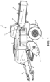
- the baler 2 has a wheeled chassis or frame including an axle 4 and a pair of laterally spaced wheels 6 that support the chassis above the ground.
- the baler 2 is provided with a forwardly extending tongue 8 for connecting the baler 2 to a towing vehicle, such as a tractor 80 ( Figure 16).
- the baler 2 additionally comprises a baling chamber 10, extending generally in a fore- and-aft direction and which are supported on the chassis.
- the baler 2 is provided with a pick up apparatus 12 by which harvested crop material arranged in a windrow on a ground surface may be lifted and directed towards the baling chamber 10.
- the harvested crop material is directed to a stuffer chute at a forward end of the baling chamber 10.
- the harvested crop material there forms a flake of harvested crop material.
- the baler 2 is further provided with a reciprocating plunger that compresses the flake of harvested crop and pushes it rearwards into the baling chamber 10 to generate a forming bale within the baling chamber. Movement of the plunger is enabled by a drive connection 14 adapted to be connected to a Power Take Off (PTO) of the towing vehicle.
- PTO Power Take Off
- the baler 2 additionally comprises a plurality of knotter units 16 immediately downstream of the baling chamber 10 for tying one or more strands of binding material (such as twine, wire, cord or the like) around the bales of crop material being formed in the baling chambers.
- binding material such as twine, wire, cord or the like
- the formed bale is directed to a discharge or ejection chute 18.
- the baling chamber 10 and the discharge chute 18 may be formed as a single channel.
- the discharge chute 18 may be coupled to the baling chamber 10 in any suitable manner.
- the preference is to form the ejection chute of the present invention as part of the channel forming the baling chamber to avoid lengthening this channel.
- certain advantages may still be obtained by forming the ejection chute of the present invention as a "bolt-on" component to existing ejection chutes.
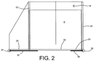
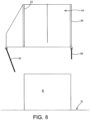
- the ejection chute 18 comprises a channel having a base wall 20 and first and second side walls 22,24 extending upwards from either side of the base wall 20.
- the base wall 20 conveniently includes an outwardly extending flange 26 extending to one side of the ejection chute 18.
- the ejection chute 18 may optionally include an upper wall extending between the first and second side walls 22,24.
- a region of the base wall is provided with an opening or window 30.
- the window 30 is suitable shaped and sized to allow a formed bale B to pass though the window 30.
- a first selectively displaceable panel 32 is adapted to pivot about a longitudinal axis 34 located to a first side of the window 30. In the illustrated embodiment the longitudinal axis 34 of the first selectively displaceable panel 32 extends along a distal end of the flange 26.
- a second selectively displaceable panel 36 is adapted to pivot about a longitudinal axis 38 located at a second side of the window. In the illustrated embodiment the longitudinal axis 38 of the second selectively displaceable panel 36 extends along a base of the second wall 24.
- the first and second selectively displaceable panels 32,36 are operable between a first position in which travel of a formed bale through the window 30 is prevented by the first and second selectively displaceable panels 32,36 and a second position in which controlled egress of the formed bale through the window is permitted (as described below). As such, operation of the first and second selectively displaceable panels 32,36 provides a deposit mechanism for controlled deposit of the formed bales through the window 30.
- first and second selectively displaceable panels 32,36 it is not necessary for the first and second selectively displaceable panels 32,36 to extend across the window 30. In the illustrated embodiment, the first and second selectively displaceable panels 32,36 only extend part way across the window 30 and are sufficient to retain the formed bale B within the ejection chute 18.
- the first and second selectively displaceable panels 32,36 are each provided with suitable actuators 40,42, for example hydraulic actuators.
- a controller 44 is provided to control movement of the actuators 40,42 and so movement of the first and second selectively displaceable panels 32,36.
- a sensor 46 in communication with the controller 44 may optionally be provided to determine when the formed bale B is in position above the window 30.
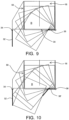
- the ejection chute 18 is also provided with a second window 50 is provided in the second side wall 24 ( Figure 9 ).
- the second window 50 is again sized and shaped to allow passage of a formed bale B.
- a lower edge of the second window 50 is contiguous with the first window 30 to form a single large opening.
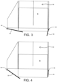
- first and second selectively displaceable panels 32,36 are actuated together to perform a linear deposit of formed bale from within the ejection chute 18.
- the actuator 40 allows a relatively small angular movement of the first selectively displaceable panel 32 and the actuator 42 allows a relatively large angular movement of the second selectively displaceable panel 36.
- the formed bale B is allowed to descend a short distance though the window 30.
- the actuator 40 ceases to move the second selectively displaceable panel 36.
- the actuator 42 continues to control movement of the first selectively displaceable panel 32 about the longitudinal axis 38 so as allow the formed bale B to descend from the ejection chute 18 in a controlled manner ( Figure 4 ).
- the bale the formed bale B is falling freely for a shorter distance than when ejected from the rear of the ejection chute.
- the formed bale B is deposited to the ground in a far more controlled manner.
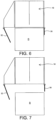
- a second deposit strategy may be adopted as illustrated in Figure 9 .
- the actuators 40, 42 are operated only to permit movement of the first selectively displaceable panel 32 about the longitudinal axis 34, with the second selectively displaceable panel 36 being held in position extending horizontally beneath the window 30.
- the formed bale B will topple over the second selectively displaceable panel 36 and as it passes through the first and second windows 30,50 perform a quarter turn.
- the substantially vertically depending first selectively displaceable panel 32 will act as a guide such that the formed bale B is directed to be deposited on the ground G on a shorter side ( Figure 9 ).
- the second selectively displaceable panel 36' may be formed as an angled plate comprising a first portion extending from the longitudinal axis 38 and a second portion extending downward at an angle to the first portion ( Figure 10 ). It will be understood that in this embodiment greater control of the quarter turn of the formed bale B is provided for as the second portion of the second selectively displaceable panel 36' and the substantially vertically depending first selectively displaceable panel 32 together provide greater guidance for the movement of the formed bale as it is deposited from the ejection chute 18 to the ground.
- FIG. 11 A further embodiment is shown in Figure 11 . While the first selectively displaceable panel 32 takes the form of the first embodiment, the ejection chute 18 is further provided with a deflector element 60.
- the deflector element 60 is substantially L-shaped.
- a first limb of the deflector 60 extends substantially vertically from the second selectively displaceable panel 36 and the second limb extends substantially horizontally inward beneath the ejection chute 18. The second limb extends further than the second selectively displaceable panel 36.
- movement of the lower end of the toppling formed bale B is further guided or constrained between a distal end of the second limb and the substantially vertically depending first selectively displaceable panel 32.
- both the first and second selectively displaceable panels 32, 36 may be operated as in the first embodiment so to allow the formed bale B to drop and be deposited on a longer side.
- the operator may select which of the drop methods is to be utilised by way of a Human Machine Interface 48 in electronic communication with the controller 44.
- the Human Machine interface 48 my be provided on the baler 2 such that a selection may be made prior to baling or incorporated into the towing vehicle, for example by being located within the driver's cab, allowing the operator to select the chosen deposit method while baling.
- the electronic controller 44 may communicate with the other elements by way of a suitable communications network 52.
- FIG. 12 A still further embodiment is shown in Figure 12 .
- a second ejection chute 118 is shown alongside the first.
- the second ejection chute 118 is provided with a first selectively displaceable panel 132 and a second selectively displaceable panel 136 to selectively obstruct a window 130 in a base wall of the second ejection chute 118.
- Additional actuators 140,142 are provided in electronic communication with the controller 44.
- An additional sensor 146 in communication with the controller 44 may optionally be provided to determine when the formed bale B' is in position above the window 130.
- the second ejector chute 118 is of similar construction to the first and second embodiments save that the constructions are reversed such that the second selectively displaceable panel 36 of the first ejection chute 18 is located adjacent the second selectively displaceable panel 136 of the second ejection chute 118. It will be understood that the controller 44 operates so that formed bales B, B1 may be ejected vertically (linear deposit mode) or rotated during deposit (quarter turn deposit mode) as desired.
- a moisture level for each formed bale may be determined.
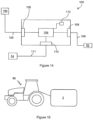
- the baler 2 may include one or more moisture sensors for monitoring a moisture level associated with the crop material collected by the pick up apparatus 12.
- the moisture sensor comprises a capacitive moisture sensor 150 mounted on an interior wall of the baling chamber 10.
- the capacitive sensor 150 has a sensing element which contacts the crop material within the baling chamber 10 in use to obtain a measurement of the moisture level associated with the crop material, as is known in the art.
- the moisture sensor 150 is used by a control system 100 of the baler 2, to determine a moisture level associated with each formed bale and determine therefrom an appropriate deposit strategy for each formed bale.
- the deposit strategy may be used by the control system 100 for controlling operational components of the baler 2, including the ejection chute for automating deposit of each formed bale in accordance with the determined deposit strategy, and/or control over a user interface 54 associated with the baler 2, e.g. provided as a display terminal of a coupled tractor 80 or indeed a handheld terminal, to provide an indication of the determined deposit strategy to an operator of the baler 2.
- a user interface 54 associated with the baler 2 e.g. provided as a display terminal of a coupled tractor 80 or indeed a handheld terminal, to provide an indication of the determined deposit strategy to an operator of the baler 2.
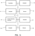
- FIG 14 illustrates the example control system 100 further.
- the control system 100 comprises a controller 102 having an electronic processor 104, an electronic input 106 and electronic outputs 108, 110.
- the processor 104 is operable to access a memory 112 of the controller 102 and execute instructions stored therein to perform the steps and functionality of the present invention discussed herein, e.g. by controlling the user interface 54, to indicate, e.g. to an operator of the baler 2, information indicative of the determined deposit strategy, and/or controlling operation of the ejection chute 18 through generation and output of one or more control signals thereto, or to a local control unit of the ejection chute 18 , e.g. control unit 72.
- the processor 104 is operable to receive sensor data via input 106 which, in the illustrated embodiment, takes the form of input signals 105 received from the moisture sensor 150. utilising this data, the processor 104 is configured to analyse the data and determine therefrom a measure of a moisture level associated with the material collected by the baler 2. As discussed herein, the determined moisture level is used to determine a deposit strategy for the baler 2, and in particular an indication of the deposit mode. A notification indicative thereof can be presented to an operator of the baler 2 via the user interface 54.
- the controller 102 includes an electronic output 108 configured output control signals 109 generated by the processor 104 for controlling operation of the ejection chute 18.
- processor 104 is operable to generate, and the controller 102 operable to then output via electronic output 108, control signals 109 for controlling operation of the ejection chute 18 in the manner described herein, e.g. through selection of the appropriate deposit mode (as determined by the deposit strategy), controlling movement of the displaceable panels 32, 36 as required.
- the controller 102 may output the control signals 109 to a local processing unit, e.g. the control unit 72 of the ejection chute 18 for controlling operation thereof.
- Electronic output 110 is operably coupled to the user interface 54 of the baler 2.
- the control system 100 is operable to control operation of the user interface 54, e.g. through output of control signals 111 in order to display data to an operator of the baler 2 relating to the operation of the control system 100.
- the control system 100 is operable to control the user interface 54 to display to the operator an indicator of the deposit strategy.
- the electronic input may additionally or alternatively receive data representative of other machine parameters including for example receiving sensor data based on bale length, bale weight or flake count of the one or more formed bales within the ejection chute to determine a deposit strategy.
- the moisture sensor is a NIR (near infrared) sensor
- the machine parameter may include one or more of the determined protein content, fibre content, nitrate content, ash content, moisture content, nitrate content or ash content of the formed bale.
- the deposit strategy may be determined to separate the bales deemed to have an overly high moisture content, by configuring the baling strategy to deposit such bales in a first mode and all remaining bales in a second mode to show the stacker or operator that that any individual bale deposited meets or does not meet the predetermined moisture criteria.
- a deposit strategy may be implemented to alert a stacker or operator of a different condition such as bale length (if the bale was too long or too short), weight (if the bale was too heavy or light), or flake count (if there were too many or too few flakes in a given formed bale).
- a strategy could be set by the operator in the user interface 54.
- FIG 15 illustrates an agricultural vehicle in the form of a tractor 1 operably coupled to baler 2. It will be appreciated that, in use, the tractor 1 and baler 2 may be operably coupled at tow hitch of the baler 2, although other couplings are envisaged and will be appreciated by the skilled reader.
Landscapes
- Life Sciences & Earth Sciences (AREA)
- Environmental Sciences (AREA)
- Preliminary Treatment Of Fibers (AREA)
- Harvester Elements (AREA)
Claims (21)
- Steuersystem zum Steuern eines Betriebs einer oder mehrerer steuerbarer Komponenten einer landwirtschaftlichen Ballenpresse (2), wobei das Steuersystem eine oder mehrere Steuerungen (44) aufweist und ausgebildet ist, um: Daten zu empfangen, die einen Maschinenparameter der landwirtschaftlichen Ballenpresse (2) anzeigen; in Abhängigkeit von dem Maschinenparameter eine Ablegestrategie zum Ablegen eines oder mehrerer geformter Ballen (B) von der landwirtschaftlichen Ballenpresse (2) zu ermitteln, wobei die Ablegestrategie eine Anzeige eines Ablegemodus umfasst; und ein oder mehrere Steuersignale zum Steuern einer oder mehrerer betrieblicher Komponenten, die der Ballenpresse (2) zugeordnet sind, in Abhängigkeit von der ermittelten Ballenablegestrategie zu generieren und auszugeben.
- Steuersystem nach Anspruch 1, wobei die Ablegestrategie ein Ausführen eines linearen Ablegemodus und/oder eines Vierteldrehungsablegemodus beinhalten kann.
- Steuersystem nach Anspruch 1 oder Anspruch 2, wobei das Steuersystem betreibbar ist, um eine Ablegestrategie basierend auf einem Feuchtigkeitsgehalt des einen oder der mehreren geformten Ballen zu ermitteln.
- Steuersystem nach einem der Ansprüche 1 bis 3, wobei die eine oder die mehreren betrieblichen Komponenten eine Nutzerschnittstelle aufweisen, die betreibbar ist, um einem Bediener der Ballenpresse eine Information, die die ermittelte Ablegestrategie anzeigt, zur Verfügung zu stellen.
- Steuersystem nach Anspruch 4, wobei das Steuersystem ausgebildet ist, um das eine oder die mehreren Steuersignale zum Steuern des Betriebs der Nutzerschnittstelle zu generieren und auszugeben, um einem Bediener der landwirtschaftlichen Ballenpresse die ermittelte Ablegestrategie darzustellen.
- Steuersystem nach einem der Ansprüche 1 bis 5, wobei die betriebliche Komponente einen Auswurfschacht (18) zum automatischen Ablegen eines oder mehrerer geformter Ballen (B) in Übereinstimmung mit der ermittelten Ablegestrategie aufweist.
- Steuersystem nach Anspruch 6, wobei das Steuersystem ausgebildet ist, um das eine oder die mehreren Steuersignale zum automatischen Steuern des Auswurfschachts (18) zu generieren und auszugeben, um den einen oder die mehreren geformten Ballen (B) abzulegen.
- Steuersystem nach einem der Ansprüche 1 bis 7, wobei das Steuersystem weiterhin ausgebildet ist, um: Sensordaten von einem Feuchtigkeitssensor zu empfangen, der mit der landwirtschaftlichen Ballenpresse verbunden ist; und in Abhängigkeit davon einen Feuchtigkeitsgehalt eines geformten Ballens zu ermitteln.
- Steuersystem nach Anspruch 8, wobei der Feuchtigkeitssensor aufweist: einen Infrarotsensor und/oder einen Widerstandssensor und/oder einen optischen Sensor und/oder einen kapazitiven Sensor (150).
- Steuersystem nach Anspruch 8 oder Anspruch 9, wobei der Feuchtigkeitssensor montiert ist an oder anderweitig verbunden ist mit der landwirtschaftlichen Ballenpresse (2) und ausgebildet ist, um in der landwirtschaftlichen Ballenpresse (2) gesammeltes Material zu überwachen.
- Steuersystem nach Anspruch 10, wobei der Feuchtigkeitssensor montiert ist an oder anderweitig verbunden ist mit der landwirtschaftlichen Ballenpresse (2) und ausgebildet ist, um durch eine Erntegutaufnahmeeinrichtung (12) der landwirtschaftlichen Ballenpresse (2) gesammeltes Material und/oder Material innerhalb einer Ballenpresskammer (10) der Ballenpresse (2) zu überwachen.
- Steuersystem nach einem der Ansprüche 1 bis 7, wobei das Steuersystem ausgebildet ist, um einen erwarteten Feuchtigkeitsgrad in Abhängigkeit von Daten, die die Betriebsumgebung der landwirtschaftlichen Ballenpresse (2) anzeigen, zu bestimmen.
- Steuersystem nach Anspruch 12, wobei die Betriebsumgebungsdaten eine kartierte Umgebung aufweisen, die Informationen beinhaltet, die einen gemessenen oder erwarteten Feuchtigkeitsgrad von Material an einem oder mehreren Orten innerhalb der kartierten Umgebung anzeigen.
- Steuersystem nach Anspruch 12 oder Anspruch 13, wobei die Betriebsumgebungsdaten eine Anzeige einer oder mehrerer Umgebungsbedingungen aufweisen, einschließlich einer Temperatur und/oder einer Jahreszeit und/oder einer Tageszeit und/oder einer Niederschlagsmessung und/oder einer Luftfeuchtigkeit.
- Steuersystem nach einen der Ansprüche 1 bis 14, wobei das Steuersystem ausgebildet ist, um eine Nutzereingabe zu empfangen, die einen von einem Bediener der Ballenpresse (2) zur Verfügung gestellten Feuchtigkeitsgrad anzeigt, und in Abhängigkeit davon die Ablegestrategie zu ermitteln.
- Steuersystem nach einem der Ansprüche 1 bis 15, wobei das Steuersystem betreibbar ist, um eine Ablegestrategie basierend auf einer Ballenlänge, einem Ballengewicht oder einer Lagenanzahl des einen oder der mehreren geformten Ballen (B) in dem Auswurfschacht (18) zu ermitteln.
- Steuersystem nach einem der Ansprüche 1 bis 15, wobei das Steuersystem betreibbar ist, um eine Ablegestrategie basierend auf dem ermittelten Proteingehalt und/oder Fasergehalt und/oder Nitratgehalt und/oder Aschegehalt und/oder Feuchtigkeitsgehalt des einen oder der mehreren geformten Ballen in dem Auswurfschacht zu ermitteln.
- Steuersystem mit: einem Auswurfschacht (18) zum Ablegen einer Mehrzahl von geformten Ballen (B); und einem Steuersystem nach einem der Ansprüche 1 bis 17, das ausgebildet ist, um einen Betrieb des Auswurfschachts (18) in Übereinstimmung mit einer ermittelten Ablegestrategie zu steuern.
- Landwirtschaftliche Ballenpresse (2) mit einem und/oder die steuerbar ist durch ein Steuersystem nach einem der Ansprüche 1 bis 17, oder die ein System nach Anspruch 18 aufweist.
- Verfahren zum Steuern eines Betriebs einer oder mehrerer steuerbarer Komponenten einer landwirtschaftlichen Ballenpresse (2), mit: Empfangen von Daten, die einen Maschinenparameter, der sich auf einen oder mehrere durch die landwirtschaftliche Ballenpresse (2) geformte Ballen (B) bezieht, anzeigen; Ermitteln einer Ablegestrategie zum Ablegen des einen oder der mehreren geformten Ballen (B) in Abhängigkeit von dem Maschinenparameter, wobei die Ablegestrategie eine Angabe eines Ablegemodus für jeden geformten Ballen (B) umfasst; und Steuern einer oder mehrerer betrieblicher Komponenten, die der Ballenpresse (2) zugeordnet sind, in Abhängigkeit von der ermittelten Ablegestrategie.
- Computerlesbares Programm mit Instruktionen, welche, wenn das Programm durch einen Computer ausgeführt wird, das Steuersystem nach einem der Ansprüche 1 bis 18 oder die landwirtschaftliche Ballenpresse nach Anspruch 19 veranlassen, das Verfahren nach Anspruch 20 auszuführen.
Applications Claiming Priority (1)
| Application Number | Priority Date | Filing Date | Title |
|---|---|---|---|
| US202263267970P | 2022-02-14 | 2022-02-14 |
Publications (2)
| Publication Number | Publication Date |
|---|---|
| EP4226758A1 EP4226758A1 (de) | 2023-08-16 |
| EP4226758B1 true EP4226758B1 (de) | 2024-11-13 |
Family
ID=85018036
Family Applications (1)
| Application Number | Title | Priority Date | Filing Date |
|---|---|---|---|
| EP23152647.6A Active EP4226758B1 (de) | 2022-02-14 | 2023-01-20 | Landwirtschaftliche ballenpresse |
Country Status (2)
| Country | Link |
|---|---|
| US (1) | US20230255145A1 (de) |
| EP (1) | EP4226758B1 (de) |
Families Citing this family (1)
| Publication number | Priority date | Publication date | Assignee | Title |
|---|---|---|---|---|
| WO2025149797A1 (en) * | 2024-01-10 | 2025-07-17 | Agco Corporation | Baling apparatus |
Family Cites Families (13)
| Publication number | Priority date | Publication date | Assignee | Title |
|---|---|---|---|---|
| US3161008A (en) * | 1963-04-16 | 1964-12-15 | Sperry Rand Corp | Discharge device |
| US4187941A (en) * | 1979-01-05 | 1980-02-12 | Sperry Rand Corporation | Bale restrictive flap |
| GB8508004D0 (en) * | 1985-03-27 | 1985-05-01 | British Res Agricult Eng | Balers |
| GB2444914A (en) * | 2006-12-19 | 2008-06-25 | Cnh Belgium Nv | Improvements in Agricultural Balers |
| NL1033922C2 (nl) * | 2007-06-01 | 2008-12-02 | Meijer Holland B V | Balenpers met excentrisch geplaatst kantelorgaan. |
| BE1020043A4 (nl) * | 2011-06-29 | 2013-04-02 | Cnh Belgium Nv | Landbouwbaalpers met baalpersglijbaan. |
| BE1020764A3 (nl) * | 2012-06-22 | 2014-04-01 | Cnh Belgium Nv | Balenpers voor gebruik in de landbouw met verbeterde positionering van de wrijvings-of vochtigheidssensor. |
| US9578811B2 (en) * | 2014-07-17 | 2017-02-28 | Deere & Company | Variable rate discharge system for crop accumulator |
| US10869428B2 (en) * | 2018-07-02 | 2020-12-22 | Michael Jason Grady | Baling apparatus and method |
| US11825773B2 (en) * | 2019-01-09 | 2023-11-28 | Great Plains Manufacturing, Inc. | High capacity baler |
| US11528837B2 (en) * | 2019-03-08 | 2022-12-20 | Climate Llc | Real-time agricultural recommendations using weather sensing on equipment |
| US11284567B1 (en) * | 2020-07-31 | 2022-03-29 | Awg Llc | Hay baler |
| US20230180668A1 (en) * | 2021-12-14 | 2023-06-15 | Agco Corporation | Chute assembly for agricultural baler |
-
2023
- 2023-01-20 EP EP23152647.6A patent/EP4226758B1/de active Active
- 2023-01-24 US US18/158,538 patent/US20230255145A1/en active Pending
Also Published As
| Publication number | Publication date |
|---|---|
| US20230255145A1 (en) | 2023-08-17 |
| EP4226758A1 (de) | 2023-08-16 |
Similar Documents
| Publication | Publication Date | Title |
|---|---|---|
| US8770102B2 (en) | Square baler comprising a control system | |
| EP2408291B1 (de) | Quaderballenpresse | |
| EP3398420B1 (de) | Verfahren und anordnung zur kontrolle der geschwindigkeit einer ballenpresse | |
| US9101092B2 (en) | Square baler comprising a control system | |
| US8677724B2 (en) | Round baler for baling crop residue | |
| EP3315016B1 (de) | Rundballenpresse und verfahren zur erstellung einer ertragskarte für solch eine rundballenpresse | |
| US7287365B2 (en) | Baler | |
| US7900556B2 (en) | Method for automated application of inoculants onto forage materials and measurement of moisture for optimum application | |
| EP2446733B1 (de) | Verfahren zur Ballenherstellung und landwirtschaftliche Ballenpresse | |
| US20120221213A1 (en) | Intelligent Stuffer Mechanism For Baler | |
| EP2614703B1 (de) | Ernteparameterabhängige Ballenkammerkonfigurationsanpassung | |
| EP2816889B1 (de) | Multimodales kontrollsystem für rechteckige ballenpresse und entsprechendes verfahren | |
| EP4226758B1 (de) | Landwirtschaftliche ballenpresse | |
| EP4193827B1 (de) | Ballenwickelsystem | |
| WO2012092313A1 (en) | Intelligent stuffer mechanism for baler | |
| EP3053428B2 (de) | System zur ermittlung des befüllgewichts eines fahrbaren sammelbehälters | |
| US20120245801A1 (en) | Baler Charge Indicator | |
| EP4245120B1 (de) | Ballenpressensystem mit konservierungsmittelüberwachung | |
| US20230255146A1 (en) | Ejection chute for an agricultural baler | |
| US20260076308A1 (en) | Control system and method for balers using crop constituents | |
| EP4278884A1 (de) | Ballenpressvorrichtung mit variablem konservierungssystem | |
| US20230337586A1 (en) | Agricultural Baler |
Legal Events
| Date | Code | Title | Description |
|---|---|---|---|
| PUAI | Public reference made under article 153(3) epc to a published international application that has entered the european phase |
Free format text: ORIGINAL CODE: 0009012 |
|
| STAA | Information on the status of an ep patent application or granted ep patent |
Free format text: STATUS: THE APPLICATION HAS BEEN PUBLISHED |
|
| AK | Designated contracting states |
Kind code of ref document: A1 Designated state(s): AL AT BE BG CH CY CZ DE DK EE ES FI FR GB GR HR HU IE IS IT LI LT LU LV MC ME MK MT NL NO PL PT RO RS SE SI SK SM TR |
|
| STAA | Information on the status of an ep patent application or granted ep patent |
Free format text: STATUS: REQUEST FOR EXAMINATION WAS MADE |
|
| 17P | Request for examination filed |
Effective date: 20240216 |
|
| RBV | Designated contracting states (corrected) |
Designated state(s): AL AT BE BG CH CY CZ DE DK EE ES FI FR GB GR HR HU IE IS IT LI LT LU LV MC ME MK MT NL NO PL PT RO RS SE SI SK SM TR |
|
| GRAP | Despatch of communication of intention to grant a patent |
Free format text: ORIGINAL CODE: EPIDOSNIGR1 |
|
| STAA | Information on the status of an ep patent application or granted ep patent |
Free format text: STATUS: GRANT OF PATENT IS INTENDED |
|
| INTG | Intention to grant announced |
Effective date: 20240829 |
|
| GRAS | Grant fee paid |
Free format text: ORIGINAL CODE: EPIDOSNIGR3 |
|
| GRAA | (expected) grant |
Free format text: ORIGINAL CODE: 0009210 |
|
| STAA | Information on the status of an ep patent application or granted ep patent |
Free format text: STATUS: THE PATENT HAS BEEN GRANTED |
|
| AK | Designated contracting states |
Kind code of ref document: B1 Designated state(s): AL AT BE BG CH CY CZ DE DK EE ES FI FR GB GR HR HU IE IS IT LI LT LU LV MC ME MK MT NL NO PL PT RO RS SE SI SK SM TR |
|
| REG | Reference to a national code |
Ref country code: GB Ref legal event code: FG4D |
|
| REG | Reference to a national code |
Ref country code: CH Ref legal event code: EP |
|
| REG | Reference to a national code |
Ref country code: DE Ref legal event code: R096 Ref document number: 602023000958 Country of ref document: DE |
|
| REG | Reference to a national code |
Ref country code: IE Ref legal event code: FG4D |
|
| REG | Reference to a national code |
Ref country code: LT Ref legal event code: MG9D |
|
| REG | Reference to a national code |
Ref country code: NL Ref legal event code: MP Effective date: 20241113 |
|
| PG25 | Lapsed in a contracting state [announced via postgrant information from national office to epo] |
Ref country code: HR Free format text: LAPSE BECAUSE OF FAILURE TO SUBMIT A TRANSLATION OF THE DESCRIPTION OR TO PAY THE FEE WITHIN THE PRESCRIBED TIME-LIMIT Effective date: 20241113 Ref country code: PT Free format text: LAPSE BECAUSE OF FAILURE TO SUBMIT A TRANSLATION OF THE DESCRIPTION OR TO PAY THE FEE WITHIN THE PRESCRIBED TIME-LIMIT Effective date: 20250313 Ref country code: IS Free format text: LAPSE BECAUSE OF FAILURE TO SUBMIT A TRANSLATION OF THE DESCRIPTION OR TO PAY THE FEE WITHIN THE PRESCRIBED TIME-LIMIT Effective date: 20250313 |
|
| PG25 | Lapsed in a contracting state [announced via postgrant information from national office to epo] |
Ref country code: FI Free format text: LAPSE BECAUSE OF FAILURE TO SUBMIT A TRANSLATION OF THE DESCRIPTION OR TO PAY THE FEE WITHIN THE PRESCRIBED TIME-LIMIT Effective date: 20241113 Ref country code: NL Free format text: LAPSE BECAUSE OF FAILURE TO SUBMIT A TRANSLATION OF THE DESCRIPTION OR TO PAY THE FEE WITHIN THE PRESCRIBED TIME-LIMIT Effective date: 20241113 |
|
| REG | Reference to a national code |
Ref country code: AT Ref legal event code: MK05 Ref document number: 1740867 Country of ref document: AT Kind code of ref document: T Effective date: 20241113 |
|
| PG25 | Lapsed in a contracting state [announced via postgrant information from national office to epo] |
Ref country code: BG Free format text: LAPSE BECAUSE OF FAILURE TO SUBMIT A TRANSLATION OF THE DESCRIPTION OR TO PAY THE FEE WITHIN THE PRESCRIBED TIME-LIMIT Effective date: 20241113 |
|
| PG25 | Lapsed in a contracting state [announced via postgrant information from national office to epo] |
Ref country code: ES Free format text: LAPSE BECAUSE OF FAILURE TO SUBMIT A TRANSLATION OF THE DESCRIPTION OR TO PAY THE FEE WITHIN THE PRESCRIBED TIME-LIMIT Effective date: 20241113 |
|
| PG25 | Lapsed in a contracting state [announced via postgrant information from national office to epo] |
Ref country code: NO Free format text: LAPSE BECAUSE OF FAILURE TO SUBMIT A TRANSLATION OF THE DESCRIPTION OR TO PAY THE FEE WITHIN THE PRESCRIBED TIME-LIMIT Effective date: 20250213 |
|
| PG25 | Lapsed in a contracting state [announced via postgrant information from national office to epo] |
Ref country code: LV Free format text: LAPSE BECAUSE OF FAILURE TO SUBMIT A TRANSLATION OF THE DESCRIPTION OR TO PAY THE FEE WITHIN THE PRESCRIBED TIME-LIMIT Effective date: 20241113 Ref country code: AT Free format text: LAPSE BECAUSE OF FAILURE TO SUBMIT A TRANSLATION OF THE DESCRIPTION OR TO PAY THE FEE WITHIN THE PRESCRIBED TIME-LIMIT Effective date: 20241113 Ref country code: GR Free format text: LAPSE BECAUSE OF FAILURE TO SUBMIT A TRANSLATION OF THE DESCRIPTION OR TO PAY THE FEE WITHIN THE PRESCRIBED TIME-LIMIT Effective date: 20250214 |
|
| PG25 | Lapsed in a contracting state [announced via postgrant information from national office to epo] |
Ref country code: PL Free format text: LAPSE BECAUSE OF FAILURE TO SUBMIT A TRANSLATION OF THE DESCRIPTION OR TO PAY THE FEE WITHIN THE PRESCRIBED TIME-LIMIT Effective date: 20241113 |
|
| PG25 | Lapsed in a contracting state [announced via postgrant information from national office to epo] |
Ref country code: RS Free format text: LAPSE BECAUSE OF FAILURE TO SUBMIT A TRANSLATION OF THE DESCRIPTION OR TO PAY THE FEE WITHIN THE PRESCRIBED TIME-LIMIT Effective date: 20250213 |
|
| PG25 | Lapsed in a contracting state [announced via postgrant information from national office to epo] |
Ref country code: SM Free format text: LAPSE BECAUSE OF FAILURE TO SUBMIT A TRANSLATION OF THE DESCRIPTION OR TO PAY THE FEE WITHIN THE PRESCRIBED TIME-LIMIT Effective date: 20241113 |
|
| PG25 | Lapsed in a contracting state [announced via postgrant information from national office to epo] |
Ref country code: DK Free format text: LAPSE BECAUSE OF FAILURE TO SUBMIT A TRANSLATION OF THE DESCRIPTION OR TO PAY THE FEE WITHIN THE PRESCRIBED TIME-LIMIT Effective date: 20241113 |
|
| PG25 | Lapsed in a contracting state [announced via postgrant information from national office to epo] |
Ref country code: EE Free format text: LAPSE BECAUSE OF FAILURE TO SUBMIT A TRANSLATION OF THE DESCRIPTION OR TO PAY THE FEE WITHIN THE PRESCRIBED TIME-LIMIT Effective date: 20241113 |
|
| PG25 | Lapsed in a contracting state [announced via postgrant information from national office to epo] |
Ref country code: RO Free format text: LAPSE BECAUSE OF FAILURE TO SUBMIT A TRANSLATION OF THE DESCRIPTION OR TO PAY THE FEE WITHIN THE PRESCRIBED TIME-LIMIT Effective date: 20241113 |
|
| PG25 | Lapsed in a contracting state [announced via postgrant information from national office to epo] |
Ref country code: SK Free format text: LAPSE BECAUSE OF FAILURE TO SUBMIT A TRANSLATION OF THE DESCRIPTION OR TO PAY THE FEE WITHIN THE PRESCRIBED TIME-LIMIT Effective date: 20241113 |
|
| PG25 | Lapsed in a contracting state [announced via postgrant information from national office to epo] |
Ref country code: CZ Free format text: LAPSE BECAUSE OF FAILURE TO SUBMIT A TRANSLATION OF THE DESCRIPTION OR TO PAY THE FEE WITHIN THE PRESCRIBED TIME-LIMIT Effective date: 20241113 |
|
| PG25 | Lapsed in a contracting state [announced via postgrant information from national office to epo] |
Ref country code: IT Free format text: LAPSE BECAUSE OF FAILURE TO SUBMIT A TRANSLATION OF THE DESCRIPTION OR TO PAY THE FEE WITHIN THE PRESCRIBED TIME-LIMIT Effective date: 20241113 |
|
| REG | Reference to a national code |
Ref country code: DE Ref legal event code: R097 Ref document number: 602023000958 Country of ref document: DE |
|
| PG25 | Lapsed in a contracting state [announced via postgrant information from national office to epo] |
Ref country code: SE Free format text: LAPSE BECAUSE OF FAILURE TO SUBMIT A TRANSLATION OF THE DESCRIPTION OR TO PAY THE FEE WITHIN THE PRESCRIBED TIME-LIMIT Effective date: 20241113 |
|
| PG25 | Lapsed in a contracting state [announced via postgrant information from national office to epo] |
Ref country code: MC Free format text: LAPSE BECAUSE OF FAILURE TO SUBMIT A TRANSLATION OF THE DESCRIPTION OR TO PAY THE FEE WITHIN THE PRESCRIBED TIME-LIMIT Effective date: 20241113 Ref country code: LU Free format text: LAPSE BECAUSE OF NON-PAYMENT OF DUE FEES Effective date: 20250120 |
|
| PLBE | No opposition filed within time limit |
Free format text: ORIGINAL CODE: 0009261 |
|
| STAA | Information on the status of an ep patent application or granted ep patent |
Free format text: STATUS: NO OPPOSITION FILED WITHIN TIME LIMIT |
|
| 26N | No opposition filed |
Effective date: 20250814 |
|
| PGFP | Annual fee paid to national office [announced via postgrant information from national office to epo] |
Ref country code: IE Payment date: 20260122 Year of fee payment: 4 Ref country code: DE Payment date: 20260121 Year of fee payment: 4 |
|
| PGFP | Annual fee paid to national office [announced via postgrant information from national office to epo] |
Ref country code: BE Payment date: 20260121 Year of fee payment: 4 |
|
| PGFP | Annual fee paid to national office [announced via postgrant information from national office to epo] |
Ref country code: FR Payment date: 20260123 Year of fee payment: 4 |