EP1933647B1 - Zitrusfruchtpresse - Google Patents
Zitrusfruchtpresse Download PDFInfo
- Publication number
- EP1933647B1 EP1933647B1 EP06810019A EP06810019A EP1933647B1 EP 1933647 B1 EP1933647 B1 EP 1933647B1 EP 06810019 A EP06810019 A EP 06810019A EP 06810019 A EP06810019 A EP 06810019A EP 1933647 B1 EP1933647 B1 EP 1933647B1
- Authority
- EP
- European Patent Office
- Prior art keywords
- squeezer
- fruit
- shaft
- drum
- squeezing
- Prior art date
- Legal status (The legal status is an assumption and is not a legal conclusion. Google has not performed a legal analysis and makes no representation as to the accuracy of the status listed.)
- Active
Links
Images


Classifications
-
- A—HUMAN NECESSITIES
- A23—FOODS OR FOODSTUFFS; TREATMENT THEREOF, NOT COVERED BY OTHER CLASSES
- A23N—MACHINES OR APPARATUS FOR TREATING HARVESTED FRUIT, VEGETABLES OR FLOWER BULBS IN BULK, NOT OTHERWISE PROVIDED FOR; PEELING VEGETABLES OR FRUIT IN BULK; APPARATUS FOR PREPARING ANIMAL FEEDING- STUFFS
- A23N1/00—Machines or apparatus for extracting juice
- A23N1/003—Machines or apparatus for extracting juice especially for citrus fruits
-
- A—HUMAN NECESSITIES
- A47—FURNITURE; DOMESTIC ARTICLES OR APPLIANCES; COFFEE MILLS; SPICE MILLS; SUCTION CLEANERS IN GENERAL
- A47J—KITCHEN EQUIPMENT; COFFEE MILLS; SPICE MILLS; APPARATUS FOR MAKING BEVERAGES
- A47J19/00—Household machines for straining foodstuffs; Household implements for mashing or straining foodstuffs
- A47J19/02—Citrus fruit squeezers; Other fruit juice extracting devices
- A47J19/023—Citrus fruit squeezers; Other fruit juice extracting devices including a pressing cone or reamer
Definitions
- the present invention relates to a citrus-fruit squeezer.
- the citrus-fruit squeezers are normally used in the food and catering industry field to which, for easiness, the following description will be related, in order to obtain a juice from citrus-fruits, generally oranges, to be added to other foods or to be directly drunk.
- inventive concept which is at the base of this invention can also be applied in other industries, such as for example the cosmetic one and, more generally, in all the cases in which the squeezing of a substantially spherical fruit is required for obtaining a juice.
- the state of the art related to citrus-fruit squeezers shows squeezers equipped with two female rotating drums, i.e. equipped with cavities, generally four, in which the portions of the fruit to be squeezed are inserted and of two male rotating drums, i.e. equipped with protruding elements, generally three, shaped so as to be coupled with the cavities existing on the female drums.
- Each of the aforesaid drums is mounted on a shaft with which it is integral in the movement.
- the squeezer Upstream of the various drums, the squeezer is equipped with elements for substantially cutting the fruit by half and, possibly, also with elements for its positioning both before and after the cut.
- the two female drums are parallel and placed in the upper part of the squeezer and each one contains, in the respective cavities, one of the halves in which the fruit has been cut by the cutting elements.
- Each female drum works coupled with one of the male drums, which are also parallelly arranged in the lower part of the squeezer such that, in turn, one of the relative protruding elements is inserted in the cavities of the female drum for squeezing the fruit.
- the conventional citrus-fruit squeezers can be further equipped with a feeder which is filled with the fruit for operating the squeezer in a more automatic way, an extractable container for the fruit peels and a container for the juice obtained from the squeezing, in order to facilitate the removal thereof.
- Document WO-A-2005/041695 dicloses a citrus-fruit squeezer according to the preamble of independent claim 1.
- the known squeezers present some drawbacks.
- the dimensions of the squeezer are rather considerable due to the presence of four drums and a high-powered motor for moving the four shafts.
- the dimensional sizes of a conventional squeezer are about 800 x 400 x 400 mm. This involves a difficulty in the movement of the squeezers themselves and also a remarkable bulkiness in terms of space, which is often limited in the public environments, such as bars and restaurants, in which it is mainly used.
- An aim of the present invention is to prevent the drawbacks above mentioned with a citrus-fruit squeezer with reduced dimensions and therefore easy and comfortable to carry, arrange and handle also in narrow spaces.
- a further aim of this invention is to present a citrus-fruit squeezer which is easy to clean, also in an accurate way, in view of the always stricter regulations relating to the hygienic conditions of the public environments. Still an aim of the invention is to show a citrus-fruit squeezer which is effective and, therefore, which produces a minimum waste quantity and obtains a high quantity of juice.
- an aim of the invention is to provide a citrus-fruit squeezer which is easy to use, also for not very skilled people, which is easy to carry out and with a limited cost.
- a citrus-fruit squeezer according to the invention is generally shown by numeral 1.
- Such squeezer 1 includes a frame 2, a first 4 and a second 5 shafts associated with the frame 2 and movement means 10 operating on the first 4 and the second 5 shafts.
- the squeezer 1 is characterized in that it includes a single female drum 6 integrally mounted on the first shaft 4, suitable for housing at least a portion of the fruit 3 to be squeezed and a single male drum 8 integrally mounted on the second shaft 5, suitable for cooperating with at least a portion of the female drum 6 for carrying out the squeezing of the fruit 3.
- the first shaft 4 lies on the second shaft 5 and, accordingly, also the female drum 6 is positioned substantially above the male drum 8.
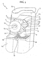
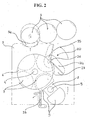
- the first and the second 5 shafts can advantageously be positioned in the frame 2 with main axes parallel and lying on an inclined plane with respect to a vertical plane for reducing the dimensions of the squeezer 1 itself and for orientating the juice coming from the squeezing in the collection zone, as it can be seen by figures 1 and 2 .
- At least one between the female drum 6 and the male drum 8, preferably both of them, can be movably mounted on the respective shafts 4, 5 through fastening means 31 so as to facilitate the dismounting and the following remounting thereof in order to carry out the cleaning or maintenance operations.
- the mentioned fastening means 31 can include a screw 32 associable with the shaft 4, 5 or an engagement element associable with the shaft 4, 5 by a joint through at least a button.
- the female drum 6 shows at least two semi-spherical seats 7 suitable for housing the portions of the fruit 3 to be squeezed, while the male drum 8 shows at least a protruding spherical element 8 suitable for the coupling with the seats 7 of the female drum 6 in order to squeeze the fruit 3.
- the female drum 6 shows four seat 7 substantially equidistant therebetween and the male drum 8 shows two spherical elements 9, also substantially equidistant therebetween ( figures 1 and 2 ).
- the citrus-fruit squeezer 1 further includes cutting means 20 arranged in correspondence with the female drum 6 for cutting in two portions the fruit 3 to be squeezed. More particularly, such means 20 include a cutting element 20 suitable for splitting the fruit 3 in a lower portion, which remains at least partially housed in one of the seats 7 of the female drum 6 and in an upper portion and an overturning element 23, associated with the cutting element 21, suitable for holding the upper portion of the fruit 3 in order to position it in the seat 7 subsequent to the one in which the relative lower portion is housed. Obviously, the portions of the fruit 3 to be squeezed are housed in the mentioned seats 7 with the peel substantially contacting the seat 7, such that the pulp to be squeezed can contact the spherical element 9 which protrudes from the male drum 8.
- the cutting element 21 includes a blade 22 arranged so as to be substantially perpendicular to the advancing direction of the female drum 6 which, preferably, shows a V-profile for facilitating the cut of the fruit 3.
- the overturning element 23 is associated with the movement means 10 in order to rotate each half turn of the first shaft 4 from a lowered portion, in which it holds the upper portion of the fruit 3, to an overturning position in which it places the upper portion of the fruit 3 in the seat 7 subsequent to the one in which the relative lower portion is housed.
- the cutting element 21 and the overturning element 23 are produced in a single metal element 24 connected to the movement means 10 for being moved each half turn of the first shaft 4 from the lowered position to the overturning one, as it can be seen in figure 2 .
- the metal element 24 is shown in a lowered position by a continuous line and in an overturning position by a dashed line.
- the metal element 25 shows a bended portion 25 having a hooking portion 26, visible in figure 4 , through which it is connected to the movement means 10 for being moved from the lowered position to the overturning one and is held in the seat through the hooking means 26 by the female drum 6, as it can be seen in figures 1 and 2 .
- the cutting means 20 can be easily disassembled through the fastening means 31 of the female drum 6.
- the metal element 24 (or the overturning element 23 when the cutting element 21 and the overturning element 23 itself are separated) is movable from the overturning position to the lowered one through a first resilient element,'generally a spring.
- the cutting means 20 also include a guide element 27 placed in correspondence with the metal element 24 and associated in a fixed way, i.e. not movable between the lowered position and the overturning position, with the frame 2 through a pin 28.
- Such guide element 27 shows a side surface properly shaped for holding the portions of the fruits 3 in the seats 7 during the rotation of the female drum 6 before the squeezing. In addition to this, such element 27 also plays the support function of the metal element 24.
- the guide element 27 is held in position by the cutting' element 21 or the metal element 24, depending on the embodiment, which in turn is maintained within the seat by the female drum 6 for being able to easily disassemble also the guide element 27 for a cleaning purpose.
- the cutting element 21 is of a fixed type, for example fixed to the guide element 27, while the overturning element 23 is movable analogously to what above described.
- the overturning element 23 can advantageously be made of a plastic material.
- the overturning element 23 can be associated with an operating resilient element, which normally maintains such element in a forward position (overturning).
- the advancing of the fruit which is cut by the cutting element 21 causes the overturning element 23 to move back (and primes the actuating spring) until a backward position, for example close to the guide element 27, but when the cut has been ended, the actuating spring again pushes forward the overturning element 23, then replacing in this way the need of a direct connection of the overturning element 23 with the movement means 10.
- the movement means 10 include an electric motor (not shown) and transmission means 11 for transmitting the movement from the motor to the first 4 and the second shaft 5.
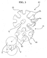
- the transmission means 11 include a cam 12 having a determined profile 13 and at least a bearing 15 suitable for movably coupling with the cam 12 along its profile 13. It is specified that in the present description, by bearing 15 any element suitable for ensuring a coupling with the cam 12 is intended.
- the cam 12 and the bearing 15 are operably interposed between the two shafts 4, 5 for transmitting the movement between the first 4 and the second 5 shafts according to a determined transmission ratio and for slowing the rotation speed of at least one of the two shafts 4, 5 during the squeezing of the fruit 3 and for subsequently speed up again the same by preferably acting such that the seat 7 of the female drum 6 is centred with the spherical element 9 of the male drum 8.
- the motor is directly operating on the second shaft 5 and moves it at a substantially constant speed.
- the cam 12 and the bearings 15, on the contrary, are respectively associated with the first 4 and the second 5 shafts so as to move the first shaft 4 by exploiting the movement imparted by the motor to the second shaft 5.
- the profile 13 of the cam 12 shows at least two U-shaped portions 14 and the transmission means 11 include at least two bearings 15 associated with a disk 16 integrally mounted on the second shaft 5, placed at different radial distances relative to the centre of the disk 16.
- the transmission means 11 include at least two bearings 15 associated with a disk 16 integrally mounted on the second shaft 5, placed at different radial distances relative to the centre of the disk 16.
- the transmission means 11 can include a number of bearings 15 different from the number of the U-shaped portions 14 of the profile 13 of the cam 12, so as to define a transmission ratio between the two shafts 4, 5 other than 1:1.
- a preferred embodiment of the squeezer 1 presents transmission means 11 with eight U-shaped portions 14 and four bearings 15 housed on two diameters substantially perpendicular therebetween of the disk 16, such that the bearings 15 housed on a diameter are placed at a radial distance lower than the one at which the bearings 15 housed on the other diameter are placed.
- This allows, as already mentioned, to halve the whole rotation speed of the first shaft 4 with respect to the second one 5 and to slow the female drum 6 during the squeezing step by keeping the seat 7 and the spherical element 9 coaxial therebetween.
- the described transmission means 11 work in such a way that during the squeezing of the fruit 3 the axis of the spherical element 9 is centred with the axis of the seat 7 (namely the axis perpendicular to the centre of the seat 7 itself) which, in turn, is aligned with one of the U-shaped portions 14 of the cam, while the spherical element 9 is aligned with the bearing 15 placed at a lower distance from the centre of the disk 16 on which is mounted.
- the squeezer 1 can show a gear transmission system suitable for carrying out the same functions of the shown cam transmission system, obviously in the possibility limits given by a gear transmission system.
- the squeezer 1 can also include a shaped extended element 33 movably associable with the frame 2 through a second resilient element having the function of removing the peel of the fruit 3 when the squeezing has been carried out by the spherical elements 9 of the male drum 8 ( figures 1 , 2 and 4 ).
- such extended element 33 can be associated with a peels collector 36 removably associable with the frame 2 such that it can be removed for being emptied and for carrying out cleaning operations ( figure 1 ).
- the squeezer 1 can further include a paddle 34 placed upstream of the female drum 6 and movably associated with the transmission.means 11 for moving itself each half turn of the first shaft 4 between a loading position, in which it loads the fruit 3 to be squeezed, and a lifted position in which it overturns and drops the fruit 3, obviously still intact, in one of the seats 7 of the female drum 6.
- the squeezer 1 can advantageously include a feeder 35 of fruits 3 placed upstream of the female drum 6 and, when existing, also upstream of the paddle 34 in order to operate such squeezer 1 in a more automatic way ( figure 1 ).
- the preferred embodiment of the squeezer 1 is completed by means 37 for collecting the juice coming from the squeezed fruits 3, associable with the frame 2.
- Such means 37 can include a conveyor for the juice which flows according to a substantially vertical direction from the point in which the squeezing occurs, to which, for example, a collecting glass can be associated.
- the collecting means 37 can include a collector 38 for the juice extractable from the frame 2.
- the used materials as well as the dimensions could be any one, depending on the requirements.
- the invention attains important advantages.
- the citrus-fruit squeezer of the invention shows very reduced dimensions with respect to the traditional squeezers and, accordingly, it results more practical and easier to handle and use.
- the dimensions have been substantially reduced of the 40%, as it is about 500 x 250 x 250 mm.
- This is due to the reduction, in this case the halving, of the number of drums, the reduction of the spherical elements of the second drum (from 3 to 2), the positioning of the two shafts obliquely relative to the vertical plane and the particular structure of the used cam transmission means.
- the transmission means structured as described, also allow to exploit at best the torque-motor power ratio and therefore to use a smaller motor with respect to the conventional squeezers.
- a squeezer according to the invention solves a problem of structural excess with respect to the known citrus-fruit squeezers, as with more or less the half of the devices of the known squeezers, it is possible to obtain the same result.
- all the main components of the squeezer such as the cutting means and the two drums, can be easily disassembled, for example by acting on the fastening means of the two shafts, with remarkable benefits in term of improvement of the cleaning easiness and therefore the service life of the squeezer itself.
- a further advantage is the fact that the slowing of the female drum and the power peak occurring in correspondence with the squeezing step are able to produce an effective squeezing and with a poor waste.
Landscapes
- Engineering & Computer Science (AREA)
- Food Science & Technology (AREA)
- Life Sciences & Earth Sciences (AREA)
- Chemical & Material Sciences (AREA)
- Polymers & Plastics (AREA)
- Apparatuses For Bulk Treatment Of Fruits And Vegetables And Apparatuses For Preparing Feeds (AREA)
- Polysaccharides And Polysaccharide Derivatives (AREA)
- Pyrane Compounds (AREA)
- Pharmaceuticals Containing Other Organic And Inorganic Compounds (AREA)
- Exhaust Silencers (AREA)
- Seal Device For Vehicle (AREA)
- Devices For Conveying Motion By Means Of Endless Flexible Members (AREA)
Claims (20)
- Zitruspresse (1) umfassend:einen Rahmen (2),eine erste Welle (4), die mit dem benannten Rahmen (2) verbunden ist,eine zweite Welle (5), die mit dem benannten Rahmen (2) verbunden ist,Bewegungsmittel (10) zum Wirken auf der benannten ersten (4) und zweiten (5) Welle, wobei die benannten Bewegungsmittel (10) einen elektrischen Motor und Übertragungsmittel (11) zum Übertragen der Bewegung vom benannten elektrischen Motor zur benannten ersten (4) und zweiten (5) Welle umfassen; eine einzelne Außentrommel (6), die an der benannten ersten Welle (4) einteilig montiert ist und zur Aufnahme von mindestens eines Teiles einer zu pressenden Frucht (3) geeignet ist, und eine einzelne Innentrommel (9), die an der benannten zweiten Welle (5) einteilig montiert ist und zur Zusammenwirkung mit mindestens einem Teil der benannten Außentrommel (6) zur Pressung der benannten Frucht (3) geeignet ist,dadurch gekennzeichnet, daß die benannten Übertragungsmittel (11) zum Definieren des Übertragungsverhältnis der benannten ersten (4) zur benannten zweiten (5) Welle und zur Verzögerung der Drehgeschwindigkeit von mindestens einer von der benannten ersten (4) und zweiten (5) Welle während der Pressung der benannten Frucht (3) und dann wiederum zu deren Beschleunigung geeignet sind.
- Zitruspresse (1) nach Anspruch 1, dadurch gekennzeichnet, daß die benannte Außentrommel (6) mindestens zwei halbkugelige Sitze (7) zur Aufnahme der benannten Teile der benannten Frucht (3) aufweist.
- Zitruspresse (1) nach Anspruch 2, dadurch gekennzeichnet, daß die benannte Innentrommel (8) mindestens ein kugeliges Element (9) zur Kopplung mit den benannten Sitzen (7) der benannten Außentrommel (6) zur Pressung der benannten Frucht (3) aufweist.
- Zitruspresse (1) nach irgendeinem der vorhergehenden Ansprüche, dadurch gekennzeichnet, daß die benannten Übertragungsmittel (11) einen Nocken (12) mit einer bestimmten Kontur (13) und mindestens einen Lager (15) zur beweglichen Kopplung mit dem benannten Nocken (12) entlang der benannten Kontur (13) umfassen.
- Zitruspresse (1) nach Anspruch 4, dadurch gekennzeichnet, daß der benannte Nocken (12) und der benannte mindestens eine Lager (15) zwischen der benannten ersten (4) und zweiten (5) Welle operativ liegen, zum Übertragen der Bewegung zwischen der benannten ersten (4) und zweiten (5) Welle gemäß einem bestimmten Übertragungsverhältnis.
- Zitruspresse (1) nach Anspruch 3 und 5, dadurch gekennzeichnet, daß der benannte Nocken (12) und der benannte mindestens eine Lager (15) zum Wirken geeignet sind, so daß der Sitz (7) der Außentrommel (6) mit dem kugeligen Element (9) der Innentrommel (8) zentriert ist.
- Zitruspresse (1) nach irgendeinem der Ansprüche 4 bis 6, dadurch gekennzeichnet, daß der benannte elektrische Motor unmittelbar auf der benannten zweiten Welle (5) wirkt, um diese mit einer wesentlich konstanten Geschwindigkeit zu bewegen, und daß der benannte Nocken (12) mit der benannten ersten Welle (4) verbunden ist, wobei der benannte mindestens eine Lager (15) mit der benannten zweiten Welle (5) zur Bewegung der benannten ersten Welle (4) verbunden ist.
- Zitruspresse (1) nach Anspruch 7, dadurch gekennzeichnet, daß die benannte Kontur (13) des benannten Nockens (12) mindestens zwei U-förmige Teile aufweist, und daß die benannten Übertragungsmittel (11) mindestens zwei von den benannten Lagern (15) umfassen, die mit einer an der benannten zweiten Welle (5) einteilig montierten Scheibe (5) verbunden sind, wobei die benannten Lager (15) in unterschiedlichen Radialabständen von der Mitte der benannten Scheibe (16) liegen, zur Bewegung der benannten ersten Welle (4) mit einer variablen Geschwindigkeit bezüglich der benannten zweiten Welle (5) mindestens während der Pressung der benannten Frucht (3).
- Zitruspresse (1) nach den Ansprüchen 7 oder 8, dadurch gekennzeichnet, daß die benannten Übertragungsmittel (11) eine andere Anzahl von den benannten Lagern (15) als die Anzahl der oben genannten U-förmigen Teile (14) der benannten Kontur (13) des benannten Nockens (12) zum Definieren des benannten Übertragungsverhältnisses der benannten ersten zur benannten zweiten (5) Welle umfassen.
- Zitruspresse (1) nach den Ansprüchen 8 und 9, dadurch gekennzeichnet, daß die benannten Übertragungsmittel (11) vier der benannten Lager (15) und acht der benannten U-förmigen Teile (15) zum Halbieren der Gesamtdrehgeschwindigkeit der benannten ersten Welle (4) bezüglich der benannten zweiten Welle (5) umfassen, und daß die benannten Lager (15) an zwei Durchmessern der benannten Scheibe (16) wesentlich orthogonal dazwischen liegen, so daß die an einem der benannten Durchmesser aufgenommenen Lager (15) in einem niedrigeren Radialabstand liegen als der Radialabstand der an dem anderen der benannten Durchmesser liegenden Lager (15), zur Verzögerung der benannten Außentrommel (6) während der Pressung der benannten Frucht (3).
- Zitruspresse (1) nach Anspruch 10, dadurch gekennzeichnet, daß während des benannten Pressungsschrittes eine Hauptachse des benannten kugeligen Elementes (9) mit einer Hauptachse des Sitzes (7), mit dem es verbunden ist, fluchtrecht ist, wobei der benannte Sitz (7) mit einem der benannten U-förmigen Konturen (13) des benannten Nockens (12) fluchtrecht ist und das benannte kugelige Element (9) mit einem der benannten Lager im benannten niedrigeren Radialabstand von der Mitte der benannten Scheibe (16) fluchtrecht ist.
- Zitruspresse (1) nach Anspruch 1 oder 2 oder 3, dadurch gekennzeichnet, daß die benannten Übertragungsmittel (11) ein Zahnradgetriebe umfassen.
- Zitruspresse (1) nach irgendeinem der vorhergehenden Ansprüche, dadurch gekennzeichnet, daß sie Schneidmittel (20) weiter umfasst, die an der benannten Außentrommel (6) liegen und auf der benannten Frucht (3) wirken, um die letztere in zwei Teile zu schneiden, wobei die benannten Schneidmittel (20) ein Schneidelement (21) zum Teilen der benannten Frucht (3) in einem Unterteil, der mindesteins teilweise in einem der benannten Sitze (7) aufgenommen ist, und in einem Oberteil, und ein Umkippelement (23) zum Halten des benannten Oberteils und zum Positionieren des benannten Oberteils in dem Sitz (7), der sich nach dem den benannten Unterteil aufnehmenden Sitz befindet,
worin das benannte Schneidelement (21) und das benannte Umkippelement (23) in einem einteiligen kippbaren Metallelement (24) hergestellt werden. - Zitruspresse (1) nach Anspruch 2 und dem vorhergehenden Anspruch, dadurch gekennzeichnet, daß das benannten Metallelement (24) einen Faltenteil (25) mit einem Einhakenteil (26) aufweist, durch den es mit den benannten Übertragungsmitteln (11) verbunden ist, zu dessen Bewegung bei jeder Halbdrehung der benannten ersten Welle (4) von der benannten abgesenkten Stellung zur benannten Umkippstellung, wobei die benannte Außentrommel (6) zum Halten im Sitz des benannten Metallelementes (24) durch den benannten Einhakenteil (26) geeignet ist.
- Zitruspresse (1) nach Anspruch 14, dadurch gekennzeichnet, daß das benannte Umkippelement (23) oder das benannte Metallelement (24) von der benannten Umkippstellung zur benannten abgesenkten Stellung durch ein erstes Federelement bewegbar sind.
- Zitruspresse (1) nach Anspruch 13, dadurch gekennzeichnet, daß sie ein wirkendes Federelement weiter umfasst, das mit dem benannten Umkippelement (23) verbunden ist, um es von der benannten abgesenkten Stellung zur benannten Umkippstellung zu verschieben.
- Zitruspresse (1) nach den Ansprüchen 14 oder 15, dadurch gekennzeichnet, daß die benannten Schneidmittel (20) ein Führungselement (27) weiter umfassen, das mit dem benannten Rahmen (2) an der benannten Außentrommel (6) verbunden ist, zum Halten der benannten Teile der benannten Früchte (3) in den benannten Sitzen (7) vor der Pressung.
- Zitruspresse (1) nach Anspruch 17, dadurch gekennzeichnet, daß das benannte Führungselement (27) durch das benannte Metallelement (24) in Position gehalten wird.
- Zitruspresse (1) nach Anspruch 13, dadurch gekennzeichnet, daß das benannte Schneidelement (21) ortsfest ist.
- Zitruspresse (1) nach irgendeinem der vorhergehenden Ansprüche, dadurch gekennzeichnet, daß sie ein geformtes erweitertes Element (33) weiter umfasst, das mit dem benannten Rahmen (2) bewegbar verbindbar ist, durch ein zweites Federelement, das zur Zusammenwirkung mit den benannten kugeligen Elementen (9) geeignet ist, um die Schale der benannten Frucht (3) von den benannten kugeligen Elementen (9) nach der Pressung der benannten Frucht (3) zu entfernen.
Applications Claiming Priority (2)
| Application Number | Priority Date | Filing Date | Title |
|---|---|---|---|
| IT000120A ITBS20050120A1 (it) | 2005-10-12 | 2005-10-12 | Macchina spremiagrumi |
| PCT/IT2006/000726 WO2007043091A2 (en) | 2005-10-12 | 2006-10-10 | Citrus-fruit squeezer |
Publications (2)
| Publication Number | Publication Date |
|---|---|
| EP1933647A2 EP1933647A2 (de) | 2008-06-25 |
| EP1933647B1 true EP1933647B1 (de) | 2009-04-01 |
Family
ID=37668231
Family Applications (1)
| Application Number | Title | Priority Date | Filing Date |
|---|---|---|---|
| EP06810019A Active EP1933647B1 (de) | 2005-10-12 | 2006-10-10 | Zitrusfruchtpresse |
Country Status (5)
| Country | Link |
|---|---|
| EP (1) | EP1933647B1 (de) |
| AT (1) | ATE427045T1 (de) |
| DE (1) | DE602006006076D1 (de) |
| IT (1) | ITBS20050120A1 (de) |
| WO (1) | WO2007043091A2 (de) |
Families Citing this family (1)
| Publication number | Priority date | Publication date | Assignee | Title |
|---|---|---|---|---|
| AT508944B1 (de) * | 2009-10-23 | 2011-08-15 | Technic Marketing Products Gmbh | Fruchtpresse |
Family Cites Families (3)
| Publication number | Priority date | Publication date | Assignee | Title |
|---|---|---|---|---|
| ES2055650B1 (es) * | 1992-02-20 | 1995-04-01 | Deza San Baudilio 50 Fernando | Maquina exprimidora de frutos. |
| FR2836016B1 (fr) * | 2002-02-21 | 2004-05-28 | Perez Tabarly Dev | Dispositif d'extractions de jus d'agrumes |
| ES2284294B1 (es) * | 2003-10-31 | 2009-04-16 | Zumex, Maquinas Y Elementos, S.A. | Maquina exprimidora de frutos citricos de tamaño reducido. |
-
2005
- 2005-10-12 IT IT000120A patent/ITBS20050120A1/it unknown
-
2006
- 2006-10-10 AT AT06810019T patent/ATE427045T1/de not_active IP Right Cessation
- 2006-10-10 EP EP06810019A patent/EP1933647B1/de active Active
- 2006-10-10 DE DE602006006076T patent/DE602006006076D1/de active Active
- 2006-10-10 WO PCT/IT2006/000726 patent/WO2007043091A2/en not_active Ceased
Also Published As
| Publication number | Publication date |
|---|---|
| EP1933647A2 (de) | 2008-06-25 |
| ATE427045T1 (de) | 2009-04-15 |
| WO2007043091A2 (en) | 2007-04-19 |
| DE602006006076D1 (de) | 2009-05-14 |
| ITBS20050120A1 (it) | 2007-04-13 |
| WO2007043091A3 (en) | 2007-09-20 |
Similar Documents
| Publication | Publication Date | Title |
|---|---|---|
| WO2010082857A1 (en) | Multifunctional kitchen appliance | |
| CN203749142U (zh) | 一种挤压式榨汁机 | |
| EP1933647B1 (de) | Zitrusfruchtpresse | |
| CN102058141B (zh) | 一种柑橘切半榨汁机 | |
| KR101675340B1 (ko) | 교체 가능한 블레이드를 포함하는 믹서기 | |
| CN216315239U (zh) | 一种鸡肉块加工用切丁装置 | |
| CN201042371Y (zh) | 一种榨汁机齿刀盘 | |
| CN222916921U (zh) | 一种鱿鱼加工切圈机 | |
| KR200322068Y1 (ko) | 다이서의 절단칼 어셈블리 | |
| CN112868733A (zh) | 一种肥牛卷切片设备 | |
| CN108818734B (zh) | 一种简单的全自动垫片模切机 | |
| CN211806444U (zh) | 山楂全自动除核切片机定位机构 | |
| CN201720872U (zh) | 一种果蔬切瓣装置 | |
| CN116000712A (zh) | 一种破碎刀用的抛光装置 | |
| CN107150372A (zh) | 一种自动剁馅机 | |
| CN2256275Y (zh) | 多功能电动食品加工机 | |
| CN2203644Y (zh) | 多功能自动切片机 | |
| CN108340427A (zh) | 多功能蔬果处理装置 | |
| CN111571659B (zh) | 一种可自动定长截断粉丝的传送台 | |
| CN214643865U (zh) | 一种食品加工用于切葱小米辣配料装置 | |
| CN111990560A (zh) | 一种果汁制备方法 | |
| CN210747130U (zh) | 一种工业用球形果蔬多工位同步削皮切分机 | |
| CN2933757Y (zh) | 丝片切削机 | |
| CN220516953U (zh) | 一种物料压平测高装置 | |
| CN220408903U (zh) | 一种中央厨房的肉类食品分切装置 |
Legal Events
| Date | Code | Title | Description |
|---|---|---|---|
| PUAI | Public reference made under article 153(3) epc to a published international application that has entered the european phase |
Free format text: ORIGINAL CODE: 0009012 |
|
| 17P | Request for examination filed |
Effective date: 20080326 |
|
| AK | Designated contracting states |
Kind code of ref document: A2 Designated state(s): AT BE BG CH CY CZ DE DK EE ES FI FR GB GR HU IE IS IT LI LT LU LV MC NL PL PT RO SE SI SK TR |
|
| GRAP | Despatch of communication of intention to grant a patent |
Free format text: ORIGINAL CODE: EPIDOSNIGR1 |
|
| DAX | Request for extension of the european patent (deleted) | ||
| GRAS | Grant fee paid |
Free format text: ORIGINAL CODE: EPIDOSNIGR3 |
|
| GRAA | (expected) grant |
Free format text: ORIGINAL CODE: 0009210 |
|
| AK | Designated contracting states |
Kind code of ref document: B1 Designated state(s): AT BE BG CH CY CZ DE DK EE ES FI FR GB GR HU IE IS IT LI LT LU LV MC NL PL PT RO SE SI SK TR |
|
| REG | Reference to a national code |
Ref country code: GB Ref legal event code: FG4D |
|
| REG | Reference to a national code |
Ref country code: CH Ref legal event code: EP |
|
| REG | Reference to a national code |
Ref country code: IE Ref legal event code: FG4D |
|
| REF | Corresponds to: |
Ref document number: 602006006076 Country of ref document: DE Date of ref document: 20090514 Kind code of ref document: P |
|
| PG25 | Lapsed in a contracting state [announced via postgrant information from national office to epo] |
Ref country code: SI Free format text: LAPSE BECAUSE OF FAILURE TO SUBMIT A TRANSLATION OF THE DESCRIPTION OR TO PAY THE FEE WITHIN THE PRESCRIBED TIME-LIMIT Effective date: 20090401 |
|
| NLV1 | Nl: lapsed or annulled due to failure to fulfill the requirements of art. 29p and 29m of the patents act | ||
| PG25 | Lapsed in a contracting state [announced via postgrant information from national office to epo] |
Ref country code: EE Free format text: LAPSE BECAUSE OF FAILURE TO SUBMIT A TRANSLATION OF THE DESCRIPTION OR TO PAY THE FEE WITHIN THE PRESCRIBED TIME-LIMIT Effective date: 20090401 Ref country code: ES Free format text: LAPSE BECAUSE OF FAILURE TO SUBMIT A TRANSLATION OF THE DESCRIPTION OR TO PAY THE FEE WITHIN THE PRESCRIBED TIME-LIMIT Effective date: 20090712 Ref country code: PT Free format text: LAPSE BECAUSE OF FAILURE TO SUBMIT A TRANSLATION OF THE DESCRIPTION OR TO PAY THE FEE WITHIN THE PRESCRIBED TIME-LIMIT Effective date: 20090902 Ref country code: FI Free format text: LAPSE BECAUSE OF FAILURE TO SUBMIT A TRANSLATION OF THE DESCRIPTION OR TO PAY THE FEE WITHIN THE PRESCRIBED TIME-LIMIT Effective date: 20090401 Ref country code: AT Free format text: LAPSE BECAUSE OF FAILURE TO SUBMIT A TRANSLATION OF THE DESCRIPTION OR TO PAY THE FEE WITHIN THE PRESCRIBED TIME-LIMIT Effective date: 20090401 Ref country code: LT Free format text: LAPSE BECAUSE OF FAILURE TO SUBMIT A TRANSLATION OF THE DESCRIPTION OR TO PAY THE FEE WITHIN THE PRESCRIBED TIME-LIMIT Effective date: 20090401 |
|
| PG25 | Lapsed in a contracting state [announced via postgrant information from national office to epo] |
Ref country code: SE Free format text: LAPSE BECAUSE OF FAILURE TO SUBMIT A TRANSLATION OF THE DESCRIPTION OR TO PAY THE FEE WITHIN THE PRESCRIBED TIME-LIMIT Effective date: 20090701 Ref country code: PL Free format text: LAPSE BECAUSE OF FAILURE TO SUBMIT A TRANSLATION OF THE DESCRIPTION OR TO PAY THE FEE WITHIN THE PRESCRIBED TIME-LIMIT Effective date: 20090401 Ref country code: NL Free format text: LAPSE BECAUSE OF FAILURE TO SUBMIT A TRANSLATION OF THE DESCRIPTION OR TO PAY THE FEE WITHIN THE PRESCRIBED TIME-LIMIT Effective date: 20090401 Ref country code: LV Free format text: LAPSE BECAUSE OF FAILURE TO SUBMIT A TRANSLATION OF THE DESCRIPTION OR TO PAY THE FEE WITHIN THE PRESCRIBED TIME-LIMIT Effective date: 20090401 Ref country code: IS Free format text: LAPSE BECAUSE OF FAILURE TO SUBMIT A TRANSLATION OF THE DESCRIPTION OR TO PAY THE FEE WITHIN THE PRESCRIBED TIME-LIMIT Effective date: 20090801 |
|
| PG25 | Lapsed in a contracting state [announced via postgrant information from national office to epo] |
Ref country code: RO Free format text: LAPSE BECAUSE OF FAILURE TO SUBMIT A TRANSLATION OF THE DESCRIPTION OR TO PAY THE FEE WITHIN THE PRESCRIBED TIME-LIMIT Effective date: 20090401 Ref country code: DK Free format text: LAPSE BECAUSE OF FAILURE TO SUBMIT A TRANSLATION OF THE DESCRIPTION OR TO PAY THE FEE WITHIN THE PRESCRIBED TIME-LIMIT Effective date: 20090401 Ref country code: CZ Free format text: LAPSE BECAUSE OF FAILURE TO SUBMIT A TRANSLATION OF THE DESCRIPTION OR TO PAY THE FEE WITHIN THE PRESCRIBED TIME-LIMIT Effective date: 20090401 |
|
| PLBE | No opposition filed within time limit |
Free format text: ORIGINAL CODE: 0009261 |
|
| STAA | Information on the status of an ep patent application or granted ep patent |
Free format text: STATUS: NO OPPOSITION FILED WITHIN TIME LIMIT |
|
| PG25 | Lapsed in a contracting state [announced via postgrant information from national office to epo] |
Ref country code: BE Free format text: LAPSE BECAUSE OF FAILURE TO SUBMIT A TRANSLATION OF THE DESCRIPTION OR TO PAY THE FEE WITHIN THE PRESCRIBED TIME-LIMIT Effective date: 20090401 Ref country code: SK Free format text: LAPSE BECAUSE OF FAILURE TO SUBMIT A TRANSLATION OF THE DESCRIPTION OR TO PAY THE FEE WITHIN THE PRESCRIBED TIME-LIMIT Effective date: 20090401 |
|
| 26N | No opposition filed |
Effective date: 20100105 |
|
| PG25 | Lapsed in a contracting state [announced via postgrant information from national office to epo] |
Ref country code: BG Free format text: LAPSE BECAUSE OF FAILURE TO SUBMIT A TRANSLATION OF THE DESCRIPTION OR TO PAY THE FEE WITHIN THE PRESCRIBED TIME-LIMIT Effective date: 20090701 |
|
| PG25 | Lapsed in a contracting state [announced via postgrant information from national office to epo] |
Ref country code: MC Free format text: LAPSE BECAUSE OF NON-PAYMENT OF DUE FEES Effective date: 20091031 |
|
| REG | Reference to a national code |
Ref country code: IE Ref legal event code: MM4A |
|
| PG25 | Lapsed in a contracting state [announced via postgrant information from national office to epo] |
Ref country code: IE Free format text: LAPSE BECAUSE OF NON-PAYMENT OF DUE FEES Effective date: 20091010 Ref country code: GR Free format text: LAPSE BECAUSE OF FAILURE TO SUBMIT A TRANSLATION OF THE DESCRIPTION OR TO PAY THE FEE WITHIN THE PRESCRIBED TIME-LIMIT Effective date: 20090702 |
|
| PG25 | Lapsed in a contracting state [announced via postgrant information from national office to epo] |
Ref country code: LU Free format text: LAPSE BECAUSE OF NON-PAYMENT OF DUE FEES Effective date: 20091010 |
|
| REG | Reference to a national code |
Ref country code: CH Ref legal event code: PL |
|
| PG25 | Lapsed in a contracting state [announced via postgrant information from national office to epo] |
Ref country code: HU Free format text: LAPSE BECAUSE OF FAILURE TO SUBMIT A TRANSLATION OF THE DESCRIPTION OR TO PAY THE FEE WITHIN THE PRESCRIBED TIME-LIMIT Effective date: 20091002 |
|
| PG25 | Lapsed in a contracting state [announced via postgrant information from national office to epo] |
Ref country code: LI Free format text: LAPSE BECAUSE OF NON-PAYMENT OF DUE FEES Effective date: 20101031 Ref country code: CH Free format text: LAPSE BECAUSE OF NON-PAYMENT OF DUE FEES Effective date: 20101031 |
|
| PG25 | Lapsed in a contracting state [announced via postgrant information from national office to epo] |
Ref country code: TR Free format text: LAPSE BECAUSE OF FAILURE TO SUBMIT A TRANSLATION OF THE DESCRIPTION OR TO PAY THE FEE WITHIN THE PRESCRIBED TIME-LIMIT Effective date: 20090401 |
|
| PG25 | Lapsed in a contracting state [announced via postgrant information from national office to epo] |
Ref country code: CY Free format text: LAPSE BECAUSE OF FAILURE TO SUBMIT A TRANSLATION OF THE DESCRIPTION OR TO PAY THE FEE WITHIN THE PRESCRIBED TIME-LIMIT Effective date: 20090401 |
|
| REG | Reference to a national code |
Ref country code: FR Ref legal event code: PLFP Year of fee payment: 10 |
|
| REG | Reference to a national code |
Ref country code: FR Ref legal event code: PLFP Year of fee payment: 11 |
|
| REG | Reference to a national code |
Ref country code: FR Ref legal event code: PLFP Year of fee payment: 12 |
|
| REG | Reference to a national code |
Ref country code: FR Ref legal event code: PLFP Year of fee payment: 13 |
|
| PGFP | Annual fee paid to national office [announced via postgrant information from national office to epo] |
Ref country code: FR Payment date: 20180920 Year of fee payment: 13 |
|
| PGFP | Annual fee paid to national office [announced via postgrant information from national office to epo] |
Ref country code: DE Payment date: 20180917 Year of fee payment: 13 |
|
| GBPC | Gb: european patent ceased through non-payment of renewal fee |
Effective date: 20181010 |
|
| PG25 | Lapsed in a contracting state [announced via postgrant information from national office to epo] |
Ref country code: GB Free format text: LAPSE BECAUSE OF NON-PAYMENT OF DUE FEES Effective date: 20181010 |
|
| REG | Reference to a national code |
Ref country code: DE Ref legal event code: R119 Ref document number: 602006006076 Country of ref document: DE |
|
| PG25 | Lapsed in a contracting state [announced via postgrant information from national office to epo] |
Ref country code: DE Free format text: LAPSE BECAUSE OF NON-PAYMENT OF DUE FEES Effective date: 20200501 |
|
| PG25 | Lapsed in a contracting state [announced via postgrant information from national office to epo] |
Ref country code: FR Free format text: LAPSE BECAUSE OF NON-PAYMENT OF DUE FEES Effective date: 20191031 |
|
| PGFP | Annual fee paid to national office [announced via postgrant information from national office to epo] |
Ref country code: IT Payment date: 20250925 Year of fee payment: 20 |