EP1932755A1 - Flotation device, method of mounting same and operation thereof - Google Patents
Flotation device, method of mounting same and operation thereof Download PDFInfo
- Publication number
- EP1932755A1 EP1932755A1 EP06819979A EP06819979A EP1932755A1 EP 1932755 A1 EP1932755 A1 EP 1932755A1 EP 06819979 A EP06819979 A EP 06819979A EP 06819979 A EP06819979 A EP 06819979A EP 1932755 A1 EP1932755 A1 EP 1932755A1
- Authority
- EP
- European Patent Office
- Prior art keywords
- receptacle
- set forth
- flotation device
- inflatable
- exterior
- Prior art date
- Legal status (The legal status is an assumption and is not a legal conclusion. Google has not performed a legal analysis and makes no representation as to the accuracy of the status listed.)
- Withdrawn
Links
- 238000005188 flotation Methods 0.000 title claims abstract description 78
- 238000000034 method Methods 0.000 title claims description 11
- 238000007667 floating Methods 0.000 claims abstract description 38
- 230000004913 activation Effects 0.000 claims abstract description 12
- 239000012530 fluid Substances 0.000 claims description 51
- 238000007789 sealing Methods 0.000 claims description 15
- 230000011664 signaling Effects 0.000 claims description 6
- 238000004873 anchoring Methods 0.000 claims description 5
- 230000000295 complement effect Effects 0.000 claims description 5
- 230000002787 reinforcement Effects 0.000 claims description 5
- 238000006073 displacement reaction Methods 0.000 claims description 4
- 231100001261 hazardous Toxicity 0.000 claims description 4
- XLYOFNOQVPJJNP-UHFFFAOYSA-N water Substances O XLYOFNOQVPJJNP-UHFFFAOYSA-N 0.000 claims description 3
- 230000006378 damage Effects 0.000 claims description 2
- 238000009966 trimming Methods 0.000 claims 2
- 238000013461 design Methods 0.000 description 2
- 230000000694 effects Effects 0.000 description 2
- 238000006467 substitution reaction Methods 0.000 description 2
- 230000003213 activating effect Effects 0.000 description 1
- 230000004075 alteration Effects 0.000 description 1
- 230000000712 assembly Effects 0.000 description 1
- 238000000429 assembly Methods 0.000 description 1
- 230000015556 catabolic process Effects 0.000 description 1
- 230000001010 compromised effect Effects 0.000 description 1
- 238000005516 engineering process Methods 0.000 description 1
- 238000003780 insertion Methods 0.000 description 1
- 230000037431 insertion Effects 0.000 description 1
- 238000012423 maintenance Methods 0.000 description 1
- 238000004519 manufacturing process Methods 0.000 description 1
- 238000005259 measurement Methods 0.000 description 1
- 230000007246 mechanism Effects 0.000 description 1
- 238000012544 monitoring process Methods 0.000 description 1
- 230000002028 premature Effects 0.000 description 1
- 238000004321 preservation Methods 0.000 description 1
- 230000008569 process Effects 0.000 description 1
- 230000003014 reinforcing effect Effects 0.000 description 1
- 239000013589 supplement Substances 0.000 description 1
- 238000011144 upstream manufacturing Methods 0.000 description 1
- 239000003643 water by type Substances 0.000 description 1
Images






Classifications
-
- B—PERFORMING OPERATIONS; TRANSPORTING
- B63—SHIPS OR OTHER WATERBORNE VESSELS; RELATED EQUIPMENT
- B63B—SHIPS OR OTHER WATERBORNE VESSELS; EQUIPMENT FOR SHIPPING
- B63B43/00—Improving safety of vessels, e.g. damage control, not otherwise provided for
- B63B43/02—Improving safety of vessels, e.g. damage control, not otherwise provided for reducing risk of capsizing or sinking
- B63B43/10—Improving safety of vessels, e.g. damage control, not otherwise provided for reducing risk of capsizing or sinking by improving buoyancy
- B63B43/14—Improving safety of vessels, e.g. damage control, not otherwise provided for reducing risk of capsizing or sinking by improving buoyancy using outboard floating members
Definitions
- the present invention relates to a flotation device and to a method of mounting same, as well to the operation of same.
- Said flotation device is designed to be housed in the interior of ships, cargo containers or floating structures in such a manner that, in emergency situations in water, the activation of said flotation device reduces the danger of sinking of the ship, cargo container or floating structure while significantly improving its buoyancy.
- the invention is such that it comprises inflatable means housed in the interior of a receptacle integrated in the body of the ship, cargo container or floating structure.
- the inflatable means are expelled to the exterior by means of thrust means following the breaking of an external cover of said receptacle, with the inflatable means being inflated subsequently in order to improve the buoyancy of the ship, cargo container or floating structure to be protected.
- the field of application of the invention lies primarily within the maritime and fluvial industry, with one or more of the flotation devices being used to protect vessels such as ships, recreational and/or fishing vessels and the like or floating structures such as oil platforms, piers and the like.
- the flotation device according to the invention is also designed for the cargo containers usually carried on the aforementioned ships and floating structures.
- said floating device optionally forms part of a more complex global system designed, to keep a ship, cargo container or floating structure afloat, comprising, for example, in addition to the flotation device according to the invention, a module for detecting hazardous situations and/or an activation control module.
- the sea, lakes and some riverbeds are and have been widely used for such activities as fishing and the transport of people and goods.
- flotation devices which turn out to be of particular interest are ones that are constituted by mechano-hydraulic elements that are housed in the interior of a ship, cargo container or floating structure to be protected and that, in the event of an emergency, improve the buoyancy by inflating some inflatable means, with said inflatable means being arranged initially in the interior of a receptacle.
- a system for maintaining ships afloat which includes, among other components, one or more buoyancy devices, is described in ES2163958 , in the name of this same applicant.
- the question of how to achieve a versatile device which is applicable to multiple ships and/or cargo containers of different shapes is not addressed specifically, nor how to achieve the correct pressure of the pressurized fluid inside the inflatable means.
- the thrust means of said buoyancy device which expel the inflatable means to the exterior, are activated by means of a first feed circuit, whereas the inflation of the inflatable means is performed using a second feed circuit different from the aforementioned, one.
- the present invention addresses the difficulties described in the foregoing by providing a new flotation device.
- the flotation device of the present invention comprises an exterior receptacle which is designed to be supported on the external surface of the ship, cargo container or floating structure to be protected such that it extends substantially inside the ship, cargo container or floating structure to be protected, leaving its open end oriented toward the outside of the ship, cargo container or floating structure to be protected; and inside of said external receptacle, the flotation device of the present invention comprises an interior receptacle whose open end corresponds to the open end of said exterior receptacle and which houses inflatable means and expulsion means in order to expel said inflatable means from the open end of said interior receptacle following the activation of the flotation device of the present invention.
- the flotation device of the present invention shall be supplemented with a source of pressurized fluid which can be connected to said exterior receptacle by means of one-way valve means in order to provide fluid to said inflatable means following the activation of the flotation device of the present invention and hence to inflate them in order to increase the buoyancy of the ship, cargo container or floating structure to be protected.
- said exterior receptacle comprises fastening means which fix said interior receptacle in position
- said interior receptacle comprises anchoring means for the anchoring of said fastening means, closure means which close off the open end of said interior receptacle, expulsion means capable of sliding toward the exterior of the open end of said interior receptacle and making said closure means break, inflatable means taken up in the cavity of said expulsion means and feeding means designed to conduct fluid to the interior of said inflatable means;
- the present invention provides a method which is different from those currently used in engineering which makes it possible for the inflation of the inflatable means to occur only when the inflatable means are already on the outside.
- FIGs 1 and 3 conjointly form a first embodiment of the flotation device of the invention, which is additionally illustrated by means of Figures 2 , 4 and 5 .
- Figure 1 shows an exterior receptacle 1 which has fastening means which comprise positioning lugs 5 and a lug crown 3 with fastening grooves 4.
- said exterior receptacle 1 has locking means 17 which comprise a positioning lug 17A and a locking guide 17B.
- Said exterior receptacle 1 also comprises signaling means which consist of a line 6.
- said exterior receptacle 1 is provided with one-way valve means which consist of a non-return valve 2, although these means may be provided at any point of the fluid supply circuit, whether inside or outside of the flotation device of the invention.
- Figure 2 shows an interior receptacle 10, formed in this embodiment by a lateral cylindrical wall 10A and a, bottom 10B, with anchoring means 7 which cooperate with said fastening grooves 4 of said exterior receptacle 1 in order to fix in position said interior receptacle in combination with the rest of said fastening means, which is to say said lug crown 3 and said positioning lugs 5.
- said interior receptacle 10 is also provided with a mooring clasp 11 designed to be immobilized in said locking means 17, particularly within said locking guide 17B.
- said mooring clasp 11 includes a mooring halyard 22 which is not visible in this figure.
- said interior receptacle 10 is closed with closure means formed by a cover 30 which includes a perimetral projection 35, and said interior receptacle 10 houses inflatable means 20 (joined to said mooring halyard 22, not visible in this figure) and expulsion means formed by a piston 12 and tiles 13.
- Said cover 30 is joined to the walls of said interior receptacle 10 by means of low-resistance screws 31.
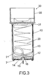
- FIG. 3 also shows feeding means which comprise tubing 15 for letting fluid in from the exterior to the inside of said interior receptacle 10 and a hose 21 emerging from the inlet of said inflatable means 20 and disposed on the inside thereof in order to direct the fluid directly to its dome.
- feeding means comprise tubing 15 for letting fluid in from the exterior to the inside of said interior receptacle 10 and a hose 21 emerging from the inlet of said inflatable means 20 and disposed on the inside thereof in order to direct the fluid directly to its dome.
- Said tubing 15 is represented as straight rigid tubing, but it is also possible for said tubing to be flexible tubing of longer length that would remain coiled during use, for example in a spiral, in the space that is present between said exterior receptacle 1 and said interior receptacle 10.
- the ends of said tubing 15 could be connected to both bends connected in a detachable, fixed or even integral manner to said exterior receptacle 1 and said interior receptacle 10, respectively.
- said hose 21 is provided with reinforcement (not shown), for example a helicoid metallic reinforcement, which prevents it from being crushed and consequently being blocked, or at least makes this more difficult.
- reinforcement for example a helicoid metallic reinforcement, which prevents it from being crushed and consequently being blocked, or at least makes this more difficult.
- the inlet of said inflatable means 20 is closed with sealing means which comprise a plug 14 and a cord 16 which joins said plug 14 to the bottom of said interior receptacle 10.
- Both the bottom of said interior receptacle 10 and the cover 30 and the piston 12 have reinforcing ribs to which no reference has been assigned, as they are not essential to the invention.
- FIG. 4 shown there is the group formed by said exterior receptacle 1 such as is represented in Figure 1 and the subgroup of components that are represented in Figure 3 . Said group is shown here already installed in the hull of a ship.
- the exterior receptacle 1 has been supported on the hull 8 of the ship in such a manner that said line 6 is inside the ship, at most touching the plane of the surface of the hull but never passing it; that the protruding part of said exterior receptacle 1 has been trimmed to be level with the hull 8 of the ship; that said interior receptacle 10 has been fastened to said exterior receptacle 1 using said fastening means 3, 4, 5; that said perimetral projection 35 has also been trimmed to be level with the hull 8 of the ship; and that the cover 30 has been filled with hardenable mass 37 until it is streamlined with the hull 8 of the ship.
- the flotation device of the invention shall be provided in a conventional manner with the relevant joints of which only a sealing ring 9 is shown in this embodiment as an example.
- FIG 5 it schematically shows the flotation device of the invention after its activation, connected by means of said non-return valve 2 to an external fluid source 40 (which is normally a container of pressurized fluid).
- an external fluid source 40 which is normally a container of pressurized fluid.
- the inflatable means 20 expelled and inflated, remain moored to said exterior receptacle 1 by means of said mooring halyard 22 and said mooring clasp 11, which bear the tension.
- the mooring tension in said inflatable means 20 is eliminated, and the resistance of the connection between said inflatable means 20 and the rest of the device of the invention is increased, hence reducing the risk of said inflatable means 20 coming loose.
- Said inflatable means 20 are provided with a safety valve 23 in such a manner that, if the pressure inside said inflatable means 20 rises above a maximum threshold (due, for example, to the partial sinking of the vessel), said safety valve 23 opens and permits the expulsion of fluid until a pressure below said maximum threshold is reached.
- said non-return valve 2 is calibrated to always supply fluid when the pressure is below said minimum threshold.
- the fluid enters under pressure through said tubing 15 and pushes said piston 12.
- Said piston 12 pushes said tiles 13 which, in their course, break the cover 30 with said hardenable mass 37.
- said cord 16 is calibrated to tension at such a distance that said piston 12 has still not reached the end of said internal receptacle but has expelled essentially all of the inflatable means 20 to the outside.
- the plug 14 pops out, opening the fluid inlet to said inflatable means 20 and permitting said inflatable means 20 to inflate.
- FIGs 6 and 8 conjointly form a second embodiment of the flotation device of the invention, which is additionally illustrated by means of Figures 7 , 9 and 10 .
- the tubing 15 is a flexible tubing having a certain length which would remain coiled during use, for example in a spiral, in the space present between said exterior receptacle 1 and said interior receptacle 10.
- the ends of said tubing 15 are coiled externally and connected to both bends connected in a detachable, fixed or even integral manner to said exterior receptacle 1 and said interior receptacle 10, respectively.
- the operator connects said tubing 15 to said exterior receptacle 1 and to said interior receptacle 10 separately by means of the coil of the tubing 15 in the respective bends, and then introduces said interior receptacle 10 into said exterior receptacle 1.
- This method of mounting eliminates the need for providing the inlets of said exterior receptacle 1 and said interior receptacle 10 with highly precise tolerances in order to achieve perfect mutual alignment, even permitting said inlets to be misaligned among themselves and/or disposed at decentralized points in relation to the bottoms of said receptacles 1, 10.
- sealing means which comprise a group formed by a mechanical shunt device 50 and direct-fill tubing 52 (in place of the plug 14 of the first embodiment) and a cord 16 which joins said group 50, 52 to the bottom of said interior receptacle 10.
- Said direct-fill tubing 52 is connected at one end to said mechanical shunt device 50 and at the other end to the fluid inlet to said inflatable means 20.
- the mechanical shunt device 50 directs the entry of fluid toward the space present between said interior receptacle 10 and said piston 12 until the pulling of the cord 16 is achieved, the pulling of which actuates said mechanical shunt device 50 such that it directs the entering fluid to said direct-fill tubing 52 so that the fluid enters directly into said inflatable means 20.
- said locking means 17 comprise a recess 17A arranged in the lateral wall of said exterior receptacle 1, a groove 17B which covers the exterior of said recess 17A and a shoe 17C with an H-shaped cross-section.
- Said recess 17A extends from the free edge of said exterior receptacle 1 initially in the axial direction and finally in the transverse direction, thus forming two portions which form a 90° angle between them.
- said mooring clasp 11 during the mounting of the device, the operator aligns said mooring clasp 11 with said recess 17A and slides said interior receptacle 10 inside said exterior receptacle 1. Subsequently, said mooring clasp 11 remains immobilized in said locking means 17A, particularly in the bottom of said recess 17A, by virtue of the insertion of said shoe 17C into said recess 17A. Specifically, said shoe 17C is inserted into said recess 17A in such a manner that the central portion of the H-section slides along said recess 17A and the wing portions of the H-section overlap with the external and internal face of said exterior receptacle 1, respectively.
- said groove 17B can be closed by means of a rigid cover joined to said groove 17B, for example by means of bolts.
- valve means can be disposed at another point upstream or downstream from the location indicated above, or they can be constituted by a plurality of individual valves which produce the required effects.
- the inflatable means can also have an asymmetrical geometric shape, that is, with the joint between the mooring halyard and the inflatable means shifted with respect to the longitudinal axis of the latter, or have a geometrical shape with one horizontal section that has a predominant face, or even both of these things.
- a specific surface of the inflatable means tends to remain in contact with the external surface of the ship, cargo container or floating structure to be protected, which prevents the halyard and the hose 21 from getting tangled or at least makes it more difficult, and allows for lighter inflatable means, since they would only need to be reinforced partially (by said specific surface) in order to tolerate the friction.
- sealing means described and illustrated here may be substituted by electronic assemblies of the type which used Hall sensors, for example, calibrated to open the inlet to the inflatable means when a predetermined displacement of the piston is produced.
- the geometric form of the inflatable means may of course be modified without this implying an alteration of the invention.
- the components of the flotation device represented as single pieces in the specific embodiments described may be modular or vice-versa: for example, the interior receptacle which is described in the embodiments as being formed by a cylindrical lateral wall and a bottom could very well be formed by a single piece.
- the flotation device of the present invention may include any accessory devices that improve the efficiency of the device, in addition to a module for detecting hazardous situations and/or a module for controlling the already-mentioned activation, which even make possible the remote and independent activation of each one of the flotation devices of the present invention mounted in the ship, cargo container or floating structure.
- the flotation device of the present invention may comprise: a motor-driven compressor which feeds fluid to the inflatable means in the event that the pressure in them needs to be increased and the pressurized fluid container used initially as an external fluid source is not being used due to depletion, breakdown, etc.; and/or at least one moisture sensor on the interior of the interior receptacle in deactivated condition to facilitate the monitoring of the preservation of the inflatable means; and/or at least one pressure sensor in activated condition which allows for measurement with sufficient notice in situations such as the depletion of the pressurized fluid source; and/or at least one device for destroying the inflatable means which can be actuated in the event that the maintenance of said activated inflatable means represents a risk or an inconvenience; and/or an inflation group using a motor-driven compressor to supply pressurized fluid to the inflatable means over an extended period as necessary; and/or even a top-refillable buoy which permits pressurized fluid to be fed to the inflatable means from outside the ship, cargo container or floating structure, optionally through the safety valve provided that its
Landscapes
- Chemical & Material Sciences (AREA)
- Engineering & Computer Science (AREA)
- Combustion & Propulsion (AREA)
- Mechanical Engineering (AREA)
- Ocean & Marine Engineering (AREA)
- Filling Or Discharging Of Gas Storage Vessels (AREA)
Abstract
Flotation device which comprises an exterior receptacle which is designed to be supported on the external surface of a ship, cargo container or floating structure in such a manner that it extends substantially within the ship, cargo container or floating structure, leaving its open end oriented toward the outside; and, inside of said exterior receptacle, an interior receptacle whose open end corresponds to the open end of said exterior receptacle and which houses inflatable means and expulsion means for expelling said inflatable means from the open end of said interior receptacle following the activation of the flotation device of the present invention.
Description
- The present invention relates to a flotation device and to a method of mounting same, as well to the operation of same.
- Said flotation device is designed to be housed in the interior of ships, cargo containers or floating structures in such a manner that, in emergency situations in water, the activation of said flotation device reduces the danger of sinking of the ship, cargo container or floating structure while significantly improving its buoyancy.
- More particularly, the invention is such that it comprises inflatable means housed in the interior of a receptacle integrated in the body of the ship, cargo container or floating structure. The inflatable means are expelled to the exterior by means of thrust means following the breaking of an external cover of said receptacle, with the inflatable means being inflated subsequently in order to improve the buoyancy of the ship, cargo container or floating structure to be protected.
- The field of application of the invention lies primarily within the maritime and fluvial industry, with one or more of the flotation devices being used to protect vessels such as ships, recreational and/or fishing vessels and the like or floating structures such as oil platforms, piers and the like.
- The flotation device according to the invention is also designed for the cargo containers usually carried on the aforementioned ships and floating structures.
- Likewise, said floating device optionally forms part of a more complex global system designed, to keep a ship, cargo container or floating structure afloat, comprising, for example, in addition to the flotation device according to the invention, a module for detecting hazardous situations and/or an activation control module.
- Use of the flotation device of the present invention in non-aquatic means of transport such as airships is not ruled out.
- The sea, lakes and some riverbeds are and have been widely used for such activities as fishing and the transport of people and goods.
- Nonetheless, being on and moving across waters is not without hazards, with the most important danger being that of the sinking of the vessel and the cargo as a consequence of the appearance of a water opening or inlet, collision, leaks, running aground, capsizing, etc.
- For this reason, various devices have been developed recently which are designed to reduce these risks, primarily by activating mechanisms which, in certain hazardous situations, increase the buoyancy of the ship, cargo container or floating structure to be protected, making it more difficult for it to sink. The majority of these devices function in a mechanical and/or hydraulic manner.
- In particular, flotation devices which turn out to be of particular interest are ones that are constituted by mechano-hydraulic elements that are housed in the interior of a ship, cargo container or floating structure to be protected and that, in the event of an emergency, improve the buoyancy by inflating some inflatable means, with said inflatable means being arranged initially in the interior of a receptacle.
- The devices described in the previous paragraph are relatively novel. What is more, the majority of the studies carried out in this area are more of a theoretical than practical nature, and there is still the need to develop flotation devices which overcome the primary disadvantages and difficulties associated with the current technology, namely:
- First of all, in order to achieve the necessary watertightness, the flotation devices need to be adapted in a precise manner to the specific contours of the ships or cargo containers in which they are to be housed, with said ships or cargo containers taking on a great variety of different practical forms.
- Accordingly, it is necessary in many cases that said devices be designed specifically for each ship, cargo container or floating structure in which they are to be housed. Moreover, in the case of ships, the design of the flotation device does not only vary as a function of the ship in question, but rather it also depends on the exact location in which the flotation device is to be housed within the hull of same. All of this makes difficult the industrial-scale production of versatile flotation devices applicable to ships or cargo containers of very different profiles.
- Another significant problem arises upon achieving an effective inflation of the inflatable means of the flotation device. In order to optimize the inflation, it is important that said procedure take place only once the process of the expulsion of the inflatable means has been completed and that said inflatable means are located outside the device. Otherwise, premature inflation of the inflatable means on the inside of the structural receptacle may lead to undesired results such as, for example, possible deformations of the inflatable means.
- On the other hand, there is still the problem of guaranteeing that, once inflated, the pressure in the inflatable means will be maintained for an adequate period of time in order to avoid a poor functioning of the system. Accordingly, if the pressure in the interior is too low, the buoyancy of the device is compromised. By contrast, if said pressure is too high, the risk of damage to the inflatable means and even a possible deformation or rupture of same increases.
- A system for maintaining ships afloat which includes, among other components, one or more buoyancy devices, is described in
ES2163958 - The present invention addresses the difficulties described in the foregoing by providing a new flotation device.
- Basically, the flotation device of the present invention comprises an exterior receptacle which is designed to be supported on the external surface of the ship, cargo container or floating structure to be protected such that it extends substantially inside the ship, cargo container or floating structure to be protected, leaving its open end oriented toward the outside of the ship, cargo container or floating structure to be protected; and inside of said external receptacle, the flotation device of the present invention comprises an interior receptacle whose open end corresponds to the open end of said exterior receptacle and which houses inflatable means and expulsion means in order to expel said inflatable means from the open end of said interior receptacle following the activation of the flotation device of the present invention.
- The flotation device of the present invention shall be supplemented with a source of pressurized fluid which can be connected to said exterior receptacle by means of one-way valve means in order to provide fluid to said inflatable means following the activation of the flotation device of the present invention and hence to inflate them in order to increase the buoyancy of the ship, cargo container or floating structure to be protected.
- To be precise, in the flotation device of the present invention, said exterior receptacle comprises fastening means which fix said interior receptacle in position, and said interior receptacle comprises anchoring means for the anchoring of said fastening means, closure means which close off the open end of said interior receptacle, expulsion means capable of sliding toward the exterior of the open end of said interior receptacle and making said closure means break, inflatable means taken up in the cavity of said expulsion means and feeding means designed to conduct fluid to the interior of said inflatable means; with the following special features:
- said exterior receptacle comprises perimetral signaling means that delimit two parts longitudinally, a first part corresponding with its open end which, during the mounting of the flotation device, is designed to protrude at least partially from the external surface of the ship, cargo container or floating structure to be protected when said exterior receptacle is supported on said external surface and to be subsequently trimmed to level, and a second part corresponding to its closed end which, during the mounting of the flotation device, is necessarily designed to be disposed in its entirety on the interior of said external surface when said external receptacle is supported on it in such a manner that said signaling means extend toward the interior of said external surface in tangential relationship therewith,
- said closure means of said interior receptacle comprise a trimmable perimetral projection designed to be trimmed during the mounting of the flotation device with the purpose of ending up level with said external surface and of being able to contain hardenable mass for the streamlining of said external surface,
- said exterior receptacle, said interior receptacle and said inflatable means each have a single inlet for pressurized fluid, and
- said inflatable means are supplemented with sealing means which, in the deactivated state, close their inlet for pressurized fluid and are calibrated to open with a predetermined displacement of said expulsion means within said interior receptacle in such a manner that, following the activation of the flotation device, said one-way valve means open and the pressurized fluid enters into said exterior receptacle and subsequently into said interior receptacle, pushing said expulsion means toward the exterior of the open end of said interior receptacle until, once sufficient displacement has occurred in order for said closure means to break, said sealing means open and the pressurized fluid enters into said inflatable means.
- In this manner, the present invention provides a method which is different from those currently used in engineering which makes it possible for the inflation of the inflatable means to occur only when the inflatable means are already on the outside.
- These and other characteristics and advantages of the invention will be made clear on the basis of the following detailed description of a preferred embodiment thereof, provided solely for the purpose of illustrative and not limiting exemplification, with respect to the enclosed drawings, in which identical numerical references correspond to same or like elements:
-
Figure 1 is a. plan view, an axial sectional view along line A-A of said plan view and a transverse section along line B-B of a detail of said axial sectional view which show an exterior receptacle in a first embodiment of the device of the invention. -
Figure 2 is a plan view and an axial sectional view along line A-A of said plan view which show an interior receptacle of said first embodiment of the device of the invention, complementary to the exterior receptacle ofFigure 1 . -
Figure 3 is an axial sectional view that shows an interior receptacle of said first embodiment of the device of the invention which corresponds to that ofFigure 2 but is provided with the rest of the components and is therefore ready for mounting in a complementary exterior receptacle. -
Figure 4 is an axial sectional view that shows said first embodiment of the device of the invention which includes said exterior receptacle ofFigure 1 and said interior receptacle ofFigure 3 , installed but in deactivated condition. -
Figure 5 shows a partial schematic view of said first embodiment of the device of the invention, installed and in activated condition. -
Figure 6 is a plan view and an axial sectional view along line A'-A' of said plan view which show an exterior receptacle of a second embodiment of the device of the invention. -
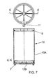
Figure 7 is a plan view and an axial sectional view along line A'-A' of said plan view which show an interior receptacle of said second embodiment of the device of the invention, complementary to the exterior receptacle ofFigure 6 . -
Figure 8 is an axial sectional view which shows an interior receptacle of said second embodiment of the device of the invention which corresponds to that ofFigure 7 but which is provided with the rest of the components and is therefore ready for mounting in a complementary exterior receptacle. -
Figure 9 is an axial sectional view which shows said second embodiment of the device of the invention which includes said exterior receptacle ofFigure 6 and said interior receptacle ofFigure 8 , installed but in deactivated condition. -
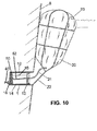
Figure 10 shows a partial schematic sectional view of said second embodiment of the device of the invention, installed and in activated condition. - In the following, a detailed description is given of the invention in making reference to the enclosed drawings (in all of which same or analogous components have been indicated with the same reference number) in accordance with some particular embodiments of same which refer to the application to a ship of the flotation device of the invention, with the understanding that it can also be applied to any other ship, to a cargo container or a floating structure.
- In these enclosed drawings, when a part is composed of various equal elements, a reference has been indicated for only one of them for the sake of clarity. Likewise, in
Figures 5 and10 , references that are not essential have been omitted, also for the sake of clarity. -
Figures 1 and3 conjointly form a first embodiment of the flotation device of the invention, which is additionally illustrated by means ofFigures 2 ,4 and5 . - More specifically.
Figure 1 . shows anexterior receptacle 1 which has fastening means which comprisepositioning lugs 5 and alug crown 3 with fastening grooves 4. In addition, saidexterior receptacle 1 has locking means 17 which comprise apositioning lug 17A and alocking guide 17B. - Said
exterior receptacle 1 also comprises signaling means which consist of aline 6. - In this embodiment, said
exterior receptacle 1 is provided with one-way valve means which consist of anon-return valve 2, although these means may be provided at any point of the fluid supply circuit, whether inside or outside of the flotation device of the invention. -
Figure 2 shows aninterior receptacle 10, formed in this embodiment by a lateralcylindrical wall 10A and a,bottom 10B, withanchoring means 7 which cooperate with said fastening grooves 4 of saidexterior receptacle 1 in order to fix in position said interior receptacle in combination with the rest of said fastening means, which is to say saidlug crown 3 and saidpositioning lugs 5. On the other hand, saidinterior receptacle 10 is also provided with amooring clasp 11 designed to be immobilized in said locking means 17, particularly within said lockingguide 17B. - said
mooring clasp 11 includes amooring halyard 22 which is not visible in this figure. - As shown in
Figure 3 , saidinterior receptacle 10 is closed with closure means formed by acover 30 which includes aperimetral projection 35, and saidinterior receptacle 10 houses inflatable means 20 (joined to saidmooring halyard 22, not visible in this figure) and expulsion means formed by apiston 12 andtiles 13. - Said
cover 30 is joined to the walls of saidinterior receptacle 10 by means of low-resistance screws 31. -
Figure 3 also shows feeding means which comprisetubing 15 for letting fluid in from the exterior to the inside of saidinterior receptacle 10 and ahose 21 emerging from the inlet of saidinflatable means 20 and disposed on the inside thereof in order to direct the fluid directly to its dome. - Said
tubing 15 is represented as straight rigid tubing, but it is also possible for said tubing to be flexible tubing of longer length that would remain coiled during use, for example in a spiral, in the space that is present between saidexterior receptacle 1 and saidinterior receptacle 10. - In this latter case, the ends of said
tubing 15 could be connected to both bends connected in a detachable, fixed or even integral manner to saidexterior receptacle 1 and saidinterior receptacle 10, respectively. - Optionally, said
hose 21 is provided with reinforcement (not shown), for example a helicoid metallic reinforcement, which prevents it from being crushed and consequently being blocked, or at least makes this more difficult. - The inlet of said
inflatable means 20 is closed with sealing means which comprise aplug 14 and acord 16 which joins saidplug 14 to the bottom of saidinterior receptacle 10. - Both the bottom of said
interior receptacle 10 and thecover 30 and thepiston 12 have reinforcing ribs to which no reference has been assigned, as they are not essential to the invention. - Now referring to
Figure 4 , shown there is the group formed by saidexterior receptacle 1 such as is represented inFigure 1 and the subgroup of components that are represented inFigure 3 . Said group is shown here already installed in the hull of a ship. - It is shown in this figure that the
exterior receptacle 1 has been supported on thehull 8 of the ship in such a manner that saidline 6 is inside the ship, at most touching the plane of the surface of the hull but never passing it; that the protruding part of saidexterior receptacle 1 has been trimmed to be level with thehull 8 of the ship; that saidinterior receptacle 10 has been fastened to saidexterior receptacle 1 using said fastening means 3, 4, 5; that saidperimetral projection 35 has also been trimmed to be level with thehull 8 of the ship; and that thecover 30 has been filled withhardenable mass 37 until it is streamlined with thehull 8 of the ship. - It should also be pointed out that said
tubing 15 is inserted in saidnon-return valve 2. - As will readily be understood, the flotation device of the invention shall be provided in a conventional manner with the relevant joints of which only a
sealing ring 9 is shown in this embodiment as an example. - Turning to
Figure 5 , it schematically shows the flotation device of the invention after its activation, connected by means of saidnon-return valve 2 to an external fluid source 40 (which is normally a container of pressurized fluid). - As can be seen, in this condition, the
inflatable means 20, expelled and inflated, remain moored to saidexterior receptacle 1 by means of saidmooring halyard 22 and saidmooring clasp 11, which bear the tension. In this manner, the mooring tension in saidinflatable means 20 is eliminated, and the resistance of the connection between saidinflatable means 20 and the rest of the device of the invention is increased, hence reducing the risk of said inflatable means 20 coming loose. - Said
inflatable means 20 are provided with asafety valve 23 in such a manner that, if the pressure inside said inflatable means 20 rises above a maximum threshold (due, for example, to the partial sinking of the vessel), saidsafety valve 23 opens and permits the expulsion of fluid until a pressure below said maximum threshold is reached. - On the other hand, in order to prevent the inflatable means 20 from being at a pressure lower than a minimum threshold (for example if, after a partial sinking of the vessel and the subsequent expulsion of fluid from said
inflatable means 20, the vessel is refloated and saidinflatable means 20 lose pressure upon approaching the surface), saidnon-return valve 2 is calibrated to always supply fluid when the pressure is below said minimum threshold. - In this manner, the pressure within the
inflatable means 20 is always maintained within an optimum range. - With respect to the method of activation, once the
non-return valve 2 is open, the fluid enters under pressure through saidtubing 15 and pushes saidpiston 12. Saidpiston 12, in turn, pushes saidtiles 13 which, in their course, break thecover 30 with saidhardenable mass 37. saidcord 16 is calibrated to tension at such a distance that saidpiston 12 has still not reached the end of said internal receptacle but has expelled essentially all of the inflatable means 20 to the outside. In this moment, theplug 14 pops out, opening the fluid inlet to saidinflatable means 20 and permitting said inflatable means 20 to inflate. - In this manner, the same fluid circuit used for the expulsion of the
inflatable means 20 is also used for the inflation of saidinflatable means 20. -
Figures 6 and8 conjointly form a second embodiment of the flotation device of the invention, which is additionally illustrated by means ofFigures 7 ,9 and10 . - For this second embodiment, only the points of distinction with respect to the already discussed first embodiment will be indicated in the following, with the purpose of avoiding unnecessary redundancies.
- Here, in accordance with the possibility pointed out previously, the
tubing 15 is a flexible tubing having a certain length which would remain coiled during use, for example in a spiral, in the space present between saidexterior receptacle 1 and saidinterior receptacle 10. - The ends of said
tubing 15 are coiled externally and connected to both bends connected in a detachable, fixed or even integral manner to saidexterior receptacle 1 and saidinterior receptacle 10, respectively. - With this configuration, during the mounting of the device, the operator connects said
tubing 15 to saidexterior receptacle 1 and to saidinterior receptacle 10 separately by means of the coil of thetubing 15 in the respective bends, and then introduces saidinterior receptacle 10 into saidexterior receptacle 1. - This method of mounting eliminates the need for providing the inlets of said
exterior receptacle 1 and saidinterior receptacle 10 with highly precise tolerances in order to achieve perfect mutual alignment, even permitting said inlets to be misaligned among themselves and/or disposed at decentralized points in relation to the bottoms of saidreceptacles - Moreover, the inlet of said
inflatable means 20 is closed by means of sealing means which comprise a group formed by amechanical shunt device 50 and direct-fill tubing 52 (in place of theplug 14 of the first embodiment) and acord 16 which joins saidgroup interior receptacle 10. - Said direct-
fill tubing 52 is connected at one end to saidmechanical shunt device 50 and at the other end to the fluid inlet to saidinflatable means 20. In this case, themechanical shunt device 50 directs the entry of fluid toward the space present between saidinterior receptacle 10 and saidpiston 12 until the pulling of thecord 16 is achieved, the pulling of which actuates saidmechanical shunt device 50 such that it directs the entering fluid to said direct-fill tubing 52 so that the fluid enters directly into saidinflatable means 20. - Finally, said locking means 17 comprise a
recess 17A arranged in the lateral wall of saidexterior receptacle 1, agroove 17B which covers the exterior of saidrecess 17A and ashoe 17C with an H-shaped cross-section.Said recess 17A extends from the free edge of saidexterior receptacle 1 initially in the axial direction and finally in the transverse direction, thus forming two portions which form a 90° angle between them. - In this second embodiment, during the mounting of the device, the operator aligns said
mooring clasp 11 with saidrecess 17A and slides saidinterior receptacle 10 inside saidexterior receptacle 1. Subsequently, saidmooring clasp 11 remains immobilized in said locking means 17A, particularly in the bottom of saidrecess 17A, by virtue of the insertion of saidshoe 17C into saidrecess 17A. Specifically, saidshoe 17C is inserted into saidrecess 17A in such a manner that the central portion of the H-section slides along saidrecess 17A and the wing portions of the H-section overlap with the external and internal face of saidexterior receptacle 1, respectively. Once the device is mounted, saidgroove 17B can be closed by means of a rigid cover joined to saidgroove 17B, for example by means of bolts. - In all of the foregoing, the present invention has been described and illustrated in accordance with some embodiments thereof. Naturally, in keeping with the principle of the invention, the embodiments and the constructional details can be varied over a broad range with respect to what has been described and illustrated without going beyond the scope of the present invention.
- Specifically, for the sake of illustration and not of limitation, the valve means can be disposed at another point upstream or downstream from the location indicated above, or they can be constituted by a plurality of individual valves which produce the required effects.
- In the same manner, the inflatable means can also have an asymmetrical geometric shape, that is, with the joint between the mooring halyard and the inflatable means shifted with respect to the longitudinal axis of the latter, or have a geometrical shape with one horizontal section that has a predominant face, or even both of these things. In this manner, in the activated state, a specific surface of the inflatable means tends to remain in contact with the external surface of the ship, cargo container or floating structure to be protected, which prevents the halyard and the
hose 21 from getting tangled or at least makes it more difficult, and allows for lighter inflatable means, since they would only need to be reinforced partially (by said specific surface) in order to tolerate the friction. - Moreover, the sealing means described and illustrated here (purely mechanical) may be substituted by electronic assemblies of the type which used Hall sensors, for example, calibrated to open the inlet to the inflatable means when a predetermined displacement of the piston is produced.
- The geometric form of the inflatable means may of course be modified without this implying an alteration of the invention. In the same manner, the components of the flotation device represented as single pieces in the specific embodiments described may be modular or vice-versa: for example, the interior receptacle which is described in the embodiments as being formed by a cylindrical lateral wall and a bottom could very well be formed by a single piece.
- Finally, the flotation device of the present invention may include any accessory devices that improve the efficiency of the device, in addition to a module for detecting hazardous situations and/or a module for controlling the already-mentioned activation, which even make possible the remote and independent activation of each one of the flotation devices of the present invention mounted in the ship, cargo container or floating structure.
- In this respect, the flotation device of the present invention may comprise: a motor-driven compressor which feeds fluid to the inflatable means in the event that the pressure in them needs to be increased and the pressurized fluid container used initially as an external fluid source is not being used due to depletion, breakdown, etc.; and/or at least one moisture sensor on the interior of the interior receptacle in deactivated condition to facilitate the monitoring of the preservation of the inflatable means; and/or at least one pressure sensor in activated condition which allows for measurement with sufficient notice in situations such as the depletion of the pressurized fluid source; and/or at least one device for destroying the inflatable means which can be actuated in the event that the maintenance of said activated inflatable means represents a risk or an inconvenience; and/or an inflation group using a motor-driven compressor to supply pressurized fluid to the inflatable means over an extended period as necessary; and/or even a top-refillable buoy which permits pressurized fluid to be fed to the inflatable means from outside the ship, cargo container or floating structure, optionally through the safety valve provided that its configuration is adequately planned.
- Even additional loose inflatable means which, by virtue of the flotation device of the invention, can be joined together using plungers should be understood, as accessory devices. In such situations, the plunger is submerged with additional empty and folded inflatable means, and they are moored to the mooring halyard and then secured to the opening for passing the fluid from the piston in substitution of the already unfolded inflatable means, proceeding them to inflate it. Such additional loose inflatable means can be connected not only in substitution of those already unfolded but also as a supplement to them, although the opening for passing the fluid from the piston must be configured appropriately beforehand, and the structural limitations of the design of the ship, cargo container or floating structure to be protected must have been confirmed.
Claims (43)
- Flotation device designed to be housed on the interior of ships, cargo containers or floating structures in such a manner that, in emergency situations in water, the activation of said flotation device reduces the danger of sinking of the ship, cargo container or floating structure while significantly improving its buoyancy, which comprises inflatable means housed on the interior of a receptacle integrated into the body of the ship, cargo container or floating structure, to be expelled to the exterior by means of respective thrust means following the breaking of an external cover of said receptacle, with the inflatable means being inflated in order to improve the buoyancy of the ship, cargo container or floating structure to be protected, characterized in that it comprises:an exterior receptacle (1) which is designed to be supported on the internal face of an external surface (8) of a ship, cargo container or floating structure, leaving its open end oriented toward the outside of said ship, cargo container or floating structure,- inside of said exterior receptacle (1), an interior receptacle (10) whose open end corresponds to the open end of said exterior receptacle (1),- closure means (30, 35) which close the open end of said interior receptacle (10),- inside of said interior receptacle (10), inflatable means (20) and expulsion means (12, 13) which can be slid along said interior receptacle (10) in order to break said closure means (30, 35) and expel said inflatable means (20) from the open end of said interior receptacle (10),- feeding means (15, 21) designed to conduct fluid to the interior of said inflatable means (20),- a pressurized fluid source which can be connected to said feeding means (15, 21),- valve means (2) interposed between said pressurized fluid source and said inflatable means (20), and- sealing means (14, 16; 50, 52) disposed at the inlet of said inflatable means (20), calibrated to allow fluid to pass to said inflatable means (20) only after a. predefined displacement of said expulsion means (12, 13) which causes the substantially complete expulsion of said inflatable means (20) from the open end of said interior receptacle (10) ;
wherein:- said exterior receptacle (1) comprises fastening means (3, 4, 5) and said interior receptacle (10) comprises anchoring means (7) for the locking thereof,- said exterior receptacle (1) comprises locking means (17, 17) and said interior receptacle (10) comprises mooring means (11) for the interlocking thereof,- said inflatable means (20) are secured to said mooring means (11) and, consequently, to said locking means (17, 17),- said exterior receptacle (1) comprises perimetral signaling means (6) which signal the degree of minimum embedding of said exterior receptacle (1) in the external surface (8) of the ship, cargo container or floating structure,- said closure means (30, 35) of said interior receptacle (10) comprise a trimmable projection, and- said exterior receptacle (1), said interior receptacle (10) and said inflatable means (20) each have a single inlet for pressurized fluid. - Flotation device as set forth in claim 1, characterized in that said valve means (2) are disposed in said exterior receptacle (1).
- Flotation device as set forth in either of claims 1 and 2, characterized in that said valve means are one-way valve means (2).
- Flotation device as set forth in claim 3, characterized in that said one-way valve means comprise a non-return valve (2).
- Flotation device as set forth in any of the foregoing claims, characterized in that said fastening means comprise positioning lugs (5) and a lug crown (3) with fastening grooves (4).
- Flotation device as set forth in any of the foregoing claims, characterized in that said locking means (17) comprise a positioning lug (17A) and a locking guide (17B).
- Flotation device as set forth in any of claims 1 to 5, characterized in that said locking means (17) comprise a recess (17A) arranged in the lateral wall of said exterior receptacle (1), a groove (17B) which covers the exterior of said recess (17A), and a shoe (17C) having an H-section, with said recess (17A) extending from the free edge of said exterior receptacle (1) initially in the axial direction and finally in the transverse direction, thus forming two portions which establish a 90° angle between them.
- Flotation device as set forth in any of the foregoing claims, characterized in that said signaling means include a line (6).
- Flotation device as set forth in any of the foregoing claims, characterized in that said inflatable means (20) are fastened to said mooring means (11) and, consequently, to said locking means (17) by means of a mooring halyard (22).
- Flotation device as set forth in any of the foregoing claims, characterized in that said mooring means comprise a mooring clasp (11) with a profile that is complementary to said locking means (17).
- Flotation device as set forth in any of the foregoing claims, characterized in that said closure means comprise a cover (30) that includes a perimetral projection (35).
- Flotation device as set forth in claim 11, characterized in that said cover (30) is joined to said interior receptacle (10) by means of low-resistance screws (31) .
- Flotation device as set forth in any of the foregoing claims, characterized in that said expulsion means comprise a piston (12) and tiles (13).
- Flotation device as set forth in any of the foregoing claims, characterized in that said feeding means comprise tubing (15) for the conduction of fluid from the exterior of said interior receptacle (10) and a hose (21) emerging from the inlet of said inflatable means (20) and disposed on the inside thereof.
- Flotation device as set forth in claim 14,
characterized in that said hose (21) is provided with reinforcement. - Flotation device as set forth in claim 15, characterized in that said reinforcement is a metallic helicoid reinforcement.
- Flotation device as set forth in any of the foregoing claims, characterized in that said sealing means comprise a plug (14) and a calibrated cord (16) which joins said plug (14) to the bottom of said interior receptacle (10).
- Flotation device as set forth in any of claims 1 to 16, characterized in that said sealing means comprise a group formed by a mechanical shunt device (50) and direct-fill tubing (52), and a calibrated cord (16) which joins said group (50, 52) to the bottom of said interior receptacle (10).
- Flotation device as set forth in any of claims 1 to 16, characterized in that said sealing means (14, 7.6; 50, 52) comprise an electronic Hall sensor assembly.
- Flotation device as set forth in any of the foregoing claims, characterized in that said interior receptacle (10) is provided with water-sealing means (9) applied to said closure means (30, 35).
- Flotation device as set forth in claim 20, characterized in that said water-sealing means include a sealing ring (9).
- Flotation device as set forth in any of the foregoing claims, characterized in that said inflatable means (20) are provided with a safety valve (23).
- Flotation device as set forth in any of the foregoing claims, characterized in that said inflatable means (20) have an asymmetrical geometric shape, with the point of union to said mooring means (11) being displaced with respect to the longitudinal axis of said inflatable means (20).
- Flotation device as set forth in any of the foregoing claims, characterized in that said inflatable means (20) have a geometric shape with a horizontal section which has a predominant face.
- Flotation device as set forth in any of the foregoing claims, characterized in that it comprises a module for detecting hazardous situations and/or a module for controlling the activation.
- Flotation device as set forth in any of the foregoing claims, characterized in that said pressurized fluid source comprises a pressurized fluid container.
- Flotation device as set forth in any of the foregoing claims, characterized in that said fluid source comprises a motor-driven compressor.
- Flotation device as set forth in any of the foregoing claims, characterized in that said interior receptacle (10) comprises at least one internal moisture sensor in deactivated condition.
- Flotation device as set forth in any of the foregoing claims, characterized in that said flotation device comprises at least one internal pressure sensor in activated condition.
- Flotation device as set forth in any of the foregoing claims, characterized in that said flotation device comprises at least one device for the destruction of the inflatable means (20).
- Flotation device as set forth in any of the foregoing claims, characterized in that said flotation device comprises a top-refillable buoy for feeding pressurized fluid to said inflatable means (20).
- Flotation device as set forth in claim 31, characterized in that the feeding of pressurized fluid to said inflatable means (20) occurs via the safety valve (23).
- Method for the mounting of a flotation device as set forth in any of the foregoing claims, characterized in that it comprises the following steps:- providing an orifice in an external surface (8) of a ship, cargo container or floating structure,- supporting said exterior receptacle (1) to the internal face of said external surface (8) of said ship, cargo container or floating structure, leaving the open end of said exterior receptacle (1) oriented toward the outside of said ship, cargo container or floating structure, protruding beyond said exterior receptacle (1) from said external surface (8) of said ship, cargo container or floating structure according to the degree of minimum embedding signaled by said signaling means (6),- trimming the protruding part of said exterior receptacle (1) to be level with said external surface (8) of said ship, cargo container or floating structure,- joining said interior receptacle (10) and said closure means (30, 35) in order to form a group of interior receptacle (10) and closure means (30, 35),- inserting said group of interior receptacle (10) and closure means (30, 35) into said exterior receptacle (1) and fastening said group to said exterior receptacle (1) using said fastening means (3, 4, 5), said anchoring means (7), said locking means (17) and said mooring means (11), with said closure means (30, 35) protruding from said external surface (8) of said ship, cargo container or floating structure, and- trimming the protruding part of said closure means (30, 35) to be level with said external surface (8) of said ship, cargo container or floating structure.
- Method of mounting as set forth in claim 33, characterized in that it comprises the following additional step:- filling said closure means (30, 35) with hardenable mass (37) until they are streamlined with said external surface (8) of said ship, cargo container or floating structure.
- Method of mounting as set forth in claim 33 and 34, characterized in that it comprises the following additional step:- connecting said pressurized fluid source to said feeding means (15, 21).
- Method of mounting as set forth in any of claims 33 to 35, characterized in that, prior to the step of inserting said group of interior receptacle (10) and closure means (30, 35) into said exterior receptacle (1) and fastening said group to said exterior receptacle (1), it comprises the following step:- connecting said tubing (15) to said interior receptacle (10) and to said exterior receptacle (1) separately.
- Operation of a flotation device as set forth with any of claims 1 to 32, characterized in that it comprises the following steps:- said valve means (2) open up and allow pressurized fluid to pass through to said exterior receptacle (1) and to said interior receptacle (10),- said expulsion means (12, 13) are pushed by said pressurized fluid, breaking said closure means (30, 35) and expelling said inflatable means (20),- said sealing means (14, 16; 50, 52) open up and allow pressurized fluid to pass through to said inflatable means (20), and- said inflatable means (20) inflate.
- Operation as set forth in claim 37, characterized in that it comprises the following additional step:- untying said inflatable means (20) from said mooring means (11).
- Operation as set forth in either of claims 37 and 38, characterized in that it comprises the following additional step:- tying at least some new inflatable means (20) to said mooring means (11).
- Operation of a flotation device as set forth in any of claims 22 and 23 to 32 when they are subordinate to claim 22, characterized in that it comprises the following steps:- said valve means (2) open up and allow pressurized fluid to pass through to said exterior receptacle (1) and to said interior receptacle (10),- said expulsion means (12, 13) are pushed by said pressurized fluid, breaking said closure means (30, 35) and expelling said inflatable means (20),- said sealing means (14, 16; 50, 52) open up and allow pressurized fluid to pass through to said inflatable means (20),- said inflatable means (20) inflate, and- said safety valve goes off and allows pressurized fluid to exit from said inflatable means (20).
- Operation as set forth in claim 40, characterized in that it comprises the following additional step:- said valve (2) open up again and allow pressurized fluid to pass through to said inflatable means (20).
- Operation as set forth in either of claims 40 and 41, characterized in that it comprises the following additional step:- untying said inflatable means (20) from said mooring means (11).
- Operation as set forth in any of claims 40 to 42, characterized in that it comprises the following additional step:- tying at least some new inflatable means (20) to said mooring means (11).
Applications Claiming Priority (2)
| Application Number | Priority Date | Filing Date | Title |
|---|---|---|---|
| ES200502177A ES2286926B1 (en) | 2005-09-07 | 2005-09-07 | FLOATING DEVICE, ASSEMBLY PROCEDURE AND OPERATION OF THE SAME. |
| PCT/ES2006/000508 WO2007028847A1 (en) | 2005-09-07 | 2006-09-07 | Flotation device, method of mounting same and operation thereof |
Publications (2)
| Publication Number | Publication Date |
|---|---|
| EP1932755A1 true EP1932755A1 (en) | 2008-06-18 |
| EP1932755A4 EP1932755A4 (en) | 2011-08-03 |
Family
ID=37835402
Family Applications (1)
| Application Number | Title | Priority Date | Filing Date |
|---|---|---|---|
| EP06819979A Withdrawn EP1932755A4 (en) | 2005-09-07 | 2006-09-07 | Flotation device, method of mounting same and operation thereof |
Country Status (5)
| Country | Link |
|---|---|
| US (1) | US20080229997A1 (en) |
| EP (1) | EP1932755A4 (en) |
| CN (1) | CN101300168A (en) |
| ES (1) | ES2286926B1 (en) |
| WO (1) | WO2007028847A1 (en) |
Cited By (2)
| Publication number | Priority date | Publication date | Assignee | Title |
|---|---|---|---|---|
| ITBO20110473A1 (en) * | 2011-07-29 | 2013-01-30 | Brunelli Pierluigi E Paola Geometri Associati | SAFETY DEVICE ANTI-SURFACE FOR BOATS AND BOAT PRESENTING THIS DEVICE |
| ITMI20120444A1 (en) * | 2012-03-21 | 2013-09-22 | Claudio Tavazzani | NAUTICAL VEHICLE WITH HULL EQUIPPED WITH INFLATABLE MEANS |
Families Citing this family (4)
| Publication number | Priority date | Publication date | Assignee | Title |
|---|---|---|---|---|
| NO330437B1 (en) * | 2009-09-29 | 2011-04-11 | Alf Egil Stensen | Protective device for a bat and method using the same |
| JP2012232764A (en) * | 2011-04-28 | 2012-11-29 | Nicchu Tohoku Bussan Kk | Container |
| FR3093818B1 (en) * | 2019-03-12 | 2021-07-23 | Tecknisolar Seni | device for the detection and geolocation of a container passed overboard |
| US20240166314A1 (en) * | 2022-11-17 | 2024-05-23 | Yacht Preserver, Llc | Yacht preserver and method of the using the yacht preserver to reduce water flow into a yacht |
Family Cites Families (13)
| Publication number | Priority date | Publication date | Assignee | Title |
|---|---|---|---|---|
| GB285774A (en) * | 1927-11-22 | 1928-02-23 | Carl Gustaf Fridholm | Arrangement on ships for preventing sinking |
| US3016858A (en) * | 1960-03-28 | 1962-01-16 | Robert Mark Johnson | Sail boat safety device |
| GB1424527A (en) * | 1972-08-18 | 1976-02-11 | Secr Defence | Method and apparatus for imparting increased buoyancy to submersible vessels |
| US4864961A (en) * | 1988-06-14 | 1989-09-12 | Slonski Richard M | Auxiliary flotation system |
| DE19709717C1 (en) * | 1997-03-10 | 1998-09-24 | Siemens Ag | Piezoelectric fuel injector regulator for IC engine |
| DE19843621B4 (en) * | 1998-09-23 | 2006-03-30 | Siemens Ag | Discharge circuit for a capacitive actuator |
| ES2163958B1 (en) * | 1998-11-14 | 2003-04-01 | Lloveres Vicente Lopez-Perea | SYSTEM TO MAINTAIN ANY TYPE OF VESSEL IN CASE OF WATER VIA. |
| DE19944733B4 (en) * | 1999-09-17 | 2007-01-04 | Siemens Ag | Device for controlling at least one capacitive actuator |
| EP1139443B1 (en) * | 2000-04-01 | 2009-09-23 | Robert Bosch GmbH | Method and apparatus for driving a piezoelectric fuel injector element |
| US6550415B2 (en) * | 2001-07-18 | 2003-04-22 | Vicente Lopez-Perea Lloveres | System to keep any type of vessel afloat in case of a leak |
| DE10152270B4 (en) * | 2001-10-20 | 2004-08-05 | Robert Bosch Gmbh | Circuit arrangement for discharging a buffer capacitor |
| US6612256B1 (en) * | 2002-02-15 | 2003-09-02 | Calford S. Martin | Combination boat and distressed boat flotation apparatus and related methods |
| AU2006241232A1 (en) * | 2005-04-22 | 2006-11-02 | Darrin John Schmitt | Emergency encapsulated lift system |
-
2005
- 2005-09-07 ES ES200502177A patent/ES2286926B1/en not_active Expired - Fee Related
-
2006
- 2006-09-07 CN CNA2006800412895A patent/CN101300168A/en active Pending
- 2006-09-07 US US12/065,886 patent/US20080229997A1/en not_active Abandoned
- 2006-09-07 EP EP06819979A patent/EP1932755A4/en not_active Withdrawn
- 2006-09-07 WO PCT/ES2006/000508 patent/WO2007028847A1/en not_active Ceased
Cited By (2)
| Publication number | Priority date | Publication date | Assignee | Title |
|---|---|---|---|---|
| ITBO20110473A1 (en) * | 2011-07-29 | 2013-01-30 | Brunelli Pierluigi E Paola Geometri Associati | SAFETY DEVICE ANTI-SURFACE FOR BOATS AND BOAT PRESENTING THIS DEVICE |
| ITMI20120444A1 (en) * | 2012-03-21 | 2013-09-22 | Claudio Tavazzani | NAUTICAL VEHICLE WITH HULL EQUIPPED WITH INFLATABLE MEANS |
Also Published As
| Publication number | Publication date |
|---|---|
| CN101300168A (en) | 2008-11-05 |
| ES2286926A1 (en) | 2007-12-01 |
| EP1932755A4 (en) | 2011-08-03 |
| WO2007028847A1 (en) | 2007-03-15 |
| US20080229997A1 (en) | 2008-09-25 |
| ES2286926B1 (en) | 2008-12-01 |
Similar Documents
| Publication | Publication Date | Title |
|---|---|---|
| US8096257B2 (en) | Emergency encapsulated lift system | |
| US4864961A (en) | Auxiliary flotation system | |
| CA2458783A1 (en) | Automatic inflating watercraft flotation device | |
| US5199374A (en) | Aerial location self-actuating emergency sea surface marker for capsized vessels | |
| CA2474299A1 (en) | Swing mooring pontoon | |
| US6550415B2 (en) | System to keep any type of vessel afloat in case of a leak | |
| US20080229997A1 (en) | Flotation Device, Method of Mounting Same and Operation Thereof | |
| US6431108B1 (en) | System for keeping afloat any type of boat in case of a leak | |
| US9487926B1 (en) | On-board re-inflatable containment boom and control system | |
| KR100875469B1 (en) | submarine | |
| ITBA20120008A1 (en) | "ANTI-SURFACE EMERGENCY DEVICE THROUGH EXPULSION AND AUTOMATIC INFLATION OF BALLS, FOR VESSELS" | |
| CN100418846C (en) | Watercraft with inflatable stabilizing ring | |
| GB2354487A (en) | Water craft having longitudinal inflatable airbags | |
| DE3413483A1 (en) | Rescue apparatus for preventing a distressed ship from sinking | |
| KR200299797Y1 (en) | A verify device sunken ship location | |
| KR20220144043A (en) | Vessel rollover prevention device to prevent marine vessel sinking | |
| KR20040027306A (en) | A verify device sunken ship location | |
| DE9105728U1 (en) | Rubbing strip with integrated floating collar for sinkable watercraft | |
| ES2268991B1 (en) | PERIMETER FLOAT HANDLING DEVICE, SAME USE PROCEDURE AND INFLATABLE FLOAT ASSEMBLY FOR THE SAME. | |
| KR20200046374A (en) | In-vessel equipped air bag with no power for life-saving rollover vessels | |
| JPS62131898A (en) | Anti-sinking device for small ships | |
| ITSS960007A1 (en) | 2SA (SAFETY ANTI-SINKING SYSTEM). THE SYSTEM WORKS WITH A SORT OF AIRBAG AND IS USED TO SUPPORT THE OVERALL WEIGHT |
Legal Events
| Date | Code | Title | Description |
|---|---|---|---|
| PUAI | Public reference made under article 153(3) epc to a published international application that has entered the european phase |
Free format text: ORIGINAL CODE: 0009012 |
|
| 17P | Request for examination filed |
Effective date: 20080407 |
|
| AK | Designated contracting states |
Kind code of ref document: A1 Designated state(s): AT BE BG CH CY CZ DE DK EE ES FI FR GB GR HU IE IS IT LI LT LU LV MC NL PL PT RO SE SI SK TR |
|
| A4 | Supplementary search report drawn up and despatched |
Effective date: 20110630 |
|
| STAA | Information on the status of an ep patent application or granted ep patent |
Free format text: STATUS: THE APPLICATION HAS BEEN WITHDRAWN |
|
| 18W | Application withdrawn |
Effective date: 20111227 |