EP1932457A1 - Gerät und Verfahren zur Herstellung einer schäumenden Flüssigkeit aus löslichen Inhaltstoffen und Verdünnungsmittel - Google Patents
Gerät und Verfahren zur Herstellung einer schäumenden Flüssigkeit aus löslichen Inhaltstoffen und Verdünnungsmittel Download PDFInfo
- Publication number
- EP1932457A1 EP1932457A1 EP20060125772 EP06125772A EP1932457A1 EP 1932457 A1 EP1932457 A1 EP 1932457A1 EP 20060125772 EP20060125772 EP 20060125772 EP 06125772 A EP06125772 A EP 06125772A EP 1932457 A1 EP1932457 A1 EP 1932457A1
- Authority
- EP
- European Patent Office
- Prior art keywords
- chamber
- diluent
- liquid
- inlet
- bottom wall
- Prior art date
- Legal status (The legal status is an assumption and is not a legal conclusion. Google has not performed a legal analysis and makes no representation as to the accuracy of the status listed.)
- Withdrawn
Links
- 239000007788 liquid Substances 0.000 title claims abstract description 131
- 239000003085 diluting agent Substances 0.000 title claims abstract description 118
- 239000004615 ingredient Substances 0.000 title claims description 40
- 238000004519 manufacturing process Methods 0.000 title claims description 20
- 235000013361 beverage Nutrition 0.000 claims description 23
- 238000000034 method Methods 0.000 claims description 11
- 230000005484 gravity Effects 0.000 claims description 6
- 239000012528 membrane Substances 0.000 claims description 3
- 235000021539 instant coffee Nutrition 0.000 claims description 2
- 239000000843 powder Substances 0.000 description 24
- 239000002775 capsule Substances 0.000 description 15
- 235000013353 coffee beverage Nutrition 0.000 description 13
- 240000007154 Coffea arabica Species 0.000 description 12
- 235000016213 coffee Nutrition 0.000 description 12
- XLYOFNOQVPJJNP-UHFFFAOYSA-N water Substances O XLYOFNOQVPJJNP-UHFFFAOYSA-N 0.000 description 12
- 239000000243 solution Substances 0.000 description 9
- 230000000694 effects Effects 0.000 description 7
- 239000007787 solid Substances 0.000 description 7
- 238000002156 mixing Methods 0.000 description 6
- 235000013305 food Nutrition 0.000 description 4
- 238000004140 cleaning Methods 0.000 description 3
- 230000000295 complement effect Effects 0.000 description 3
- 239000012530 fluid Substances 0.000 description 3
- 238000002347 injection Methods 0.000 description 3
- 239000007924 injection Substances 0.000 description 3
- 235000013336 milk Nutrition 0.000 description 3
- 239000008267 milk Substances 0.000 description 3
- 210000004080 milk Anatomy 0.000 description 3
- 239000000203 mixture Substances 0.000 description 3
- 230000008901 benefit Effects 0.000 description 2
- 230000001419 dependent effect Effects 0.000 description 2
- 239000006260 foam Substances 0.000 description 2
- 239000010816 packaging waste Substances 0.000 description 2
- 239000004033 plastic Substances 0.000 description 2
- 238000002360 preparation method Methods 0.000 description 2
- 239000000126 substance Substances 0.000 description 2
- 244000269722 Thea sinensis Species 0.000 description 1
- 235000020291 caffè lungo Nutrition 0.000 description 1
- 238000010276 construction Methods 0.000 description 1
- 230000008878 coupling Effects 0.000 description 1
- 238000010168 coupling process Methods 0.000 description 1
- 238000005859 coupling reaction Methods 0.000 description 1
- 238000004090 dissolution Methods 0.000 description 1
- 238000009826 distribution Methods 0.000 description 1
- 238000005516 engineering process Methods 0.000 description 1
- 235000015114 espresso Nutrition 0.000 description 1
- 238000000605 extraction Methods 0.000 description 1
- 238000005187 foaming Methods 0.000 description 1
- 235000012041 food component Nutrition 0.000 description 1
- 239000005417 food ingredient Substances 0.000 description 1
- 239000013505 freshwater Substances 0.000 description 1
- 238000010438 heat treatment Methods 0.000 description 1
- 230000003116 impacting effect Effects 0.000 description 1
- 238000001746 injection moulding Methods 0.000 description 1
- 235000014666 liquid concentrate Nutrition 0.000 description 1
- 239000002991 molded plastic Substances 0.000 description 1
- 230000002572 peristaltic effect Effects 0.000 description 1
- 239000008237 rinsing water Substances 0.000 description 1
- 230000000630 rising effect Effects 0.000 description 1
- 238000007789 sealing Methods 0.000 description 1
- 238000010008 shearing Methods 0.000 description 1
- 238000003892 spreading Methods 0.000 description 1
- 239000007858 starting material Substances 0.000 description 1
- 230000032258 transport Effects 0.000 description 1
Images


Classifications
-
- B—PERFORMING OPERATIONS; TRANSPORTING
- B65—CONVEYING; PACKING; STORING; HANDLING THIN OR FILAMENTARY MATERIAL
- B65D—CONTAINERS FOR STORAGE OR TRANSPORT OF ARTICLES OR MATERIALS, e.g. BAGS, BARRELS, BOTTLES, BOXES, CANS, CARTONS, CRATES, DRUMS, JARS, TANKS, HOPPERS, FORWARDING CONTAINERS; ACCESSORIES, CLOSURES, OR FITTINGS THEREFOR; PACKAGING ELEMENTS; PACKAGES
- B65D85/00—Containers, packaging elements or packages, specially adapted for particular articles or materials
- B65D85/70—Containers, packaging elements or packages, specially adapted for particular articles or materials for materials not otherwise provided for
- B65D85/804—Disposable containers or packages with contents which are mixed, infused or dissolved in situ, i.e. without having been previously removed from the package
- B65D85/8043—Packages adapted to allow liquid to pass through the contents
- B65D85/8049—Details of the inlet
-
- A—HUMAN NECESSITIES
- A23—FOODS OR FOODSTUFFS; TREATMENT THEREOF, NOT COVERED BY OTHER CLASSES
- A23F—COFFEE; TEA; THEIR SUBSTITUTES; MANUFACTURE, PREPARATION, OR INFUSION THEREOF
- A23F5/00—Coffee; Coffee substitutes; Preparations thereof
- A23F5/24—Extraction of coffee; Coffee extracts; Making instant coffee
- A23F5/26—Extraction of water-soluble constituents
- A23F5/262—Extraction of water-soluble constituents the extraction liquid flows through a stationary bed of solid substances, e.g. in percolation columns
-
- A—HUMAN NECESSITIES
- A23—FOODS OR FOODSTUFFS; TREATMENT THEREOF, NOT COVERED BY OTHER CLASSES
- A23L—FOODS, FOODSTUFFS, OR NON-ALCOHOLIC BEVERAGES, NOT COVERED BY SUBCLASSES A21D OR A23B-A23J; THEIR PREPARATION OR TREATMENT, e.g. COOKING, MODIFICATION OF NUTRITIVE QUALITIES, PHYSICAL TREATMENT; PRESERVATION OF FOODS OR FOODSTUFFS, IN GENERAL
- A23L2/00—Non-alcoholic beverages; Dry compositions or concentrates therefor; Their preparation
- A23L2/52—Adding ingredients
- A23L2/54—Mixing with gases
-
- A—HUMAN NECESSITIES
- A47—FURNITURE; DOMESTIC ARTICLES OR APPLIANCES; COFFEE MILLS; SPICE MILLS; SUCTION CLEANERS IN GENERAL
- A47J—KITCHEN EQUIPMENT; COFFEE MILLS; SPICE MILLS; APPARATUS FOR MAKING BEVERAGES
- A47J31/00—Apparatus for making beverages
- A47J31/40—Beverage-making apparatus with dispensing means for adding a measured quantity of ingredients, e.g. coffee, water, sugar, cocoa, milk, tea
- A47J31/401—Beverage-making apparatus with dispensing means for adding a measured quantity of ingredients, e.g. coffee, water, sugar, cocoa, milk, tea whereby the powder ingredients and the water are delivered to a mixing bowl
-
- A—HUMAN NECESSITIES
- A47—FURNITURE; DOMESTIC ARTICLES OR APPLIANCES; COFFEE MILLS; SPICE MILLS; SUCTION CLEANERS IN GENERAL
- A47J—KITCHEN EQUIPMENT; COFFEE MILLS; SPICE MILLS; APPARATUS FOR MAKING BEVERAGES
- A47J31/00—Apparatus for making beverages
- A47J31/40—Beverage-making apparatus with dispensing means for adding a measured quantity of ingredients, e.g. coffee, water, sugar, cocoa, milk, tea
- A47J31/404—Powder dosing devices
-
- A—HUMAN NECESSITIES
- A47—FURNITURE; DOMESTIC ARTICLES OR APPLIANCES; COFFEE MILLS; SPICE MILLS; SUCTION CLEANERS IN GENERAL
- A47J—KITCHEN EQUIPMENT; COFFEE MILLS; SPICE MILLS; APPARATUS FOR MAKING BEVERAGES
- A47J31/00—Apparatus for making beverages
- A47J31/40—Beverage-making apparatus with dispensing means for adding a measured quantity of ingredients, e.g. coffee, water, sugar, cocoa, milk, tea
- A47J31/407—Beverage-making apparatus with dispensing means for adding a measured quantity of ingredients, e.g. coffee, water, sugar, cocoa, milk, tea with ingredient-containing cartridges; Cartridge-perforating means
-
- A—HUMAN NECESSITIES
- A47—FURNITURE; DOMESTIC ARTICLES OR APPLIANCES; COFFEE MILLS; SPICE MILLS; SUCTION CLEANERS IN GENERAL
- A47J—KITCHEN EQUIPMENT; COFFEE MILLS; SPICE MILLS; APPARATUS FOR MAKING BEVERAGES
- A47J31/00—Apparatus for making beverages
- A47J31/44—Parts or details or accessories of beverage-making apparatus
- A47J31/46—Dispensing spouts, pumps, drain valves or like liquid transporting devices
- A47J31/462—Dispensing spouts, pumps, drain valves or like liquid transporting devices with an intermediate liquid storage tank
-
- B—PERFORMING OPERATIONS; TRANSPORTING
- B65—CONVEYING; PACKING; STORING; HANDLING THIN OR FILAMENTARY MATERIAL
- B65D—CONTAINERS FOR STORAGE OR TRANSPORT OF ARTICLES OR MATERIALS, e.g. BAGS, BARRELS, BOTTLES, BOXES, CANS, CARTONS, CRATES, DRUMS, JARS, TANKS, HOPPERS, FORWARDING CONTAINERS; ACCESSORIES, CLOSURES, OR FITTINGS THEREFOR; PACKAGING ELEMENTS; PACKAGES
- B65D85/00—Containers, packaging elements or packages, specially adapted for particular articles or materials
- B65D85/70—Containers, packaging elements or packages, specially adapted for particular articles or materials for materials not otherwise provided for
- B65D85/804—Disposable containers or packages with contents which are mixed, infused or dissolved in situ, i.e. without having been previously removed from the package
- B65D85/8043—Packages adapted to allow liquid to pass through the contents
- B65D85/8052—Details of the outlet
-
- A—HUMAN NECESSITIES
- A23—FOODS OR FOODSTUFFS; TREATMENT THEREOF, NOT COVERED BY OTHER CLASSES
- A23V—INDEXING SCHEME RELATING TO FOODS, FOODSTUFFS OR NON-ALCOHOLIC BEVERAGES AND LACTIC OR PROPIONIC ACID BACTERIA USED IN FOODSTUFFS OR FOOD PREPARATION
- A23V2002/00—Food compositions, function of food ingredients or processes for food or foodstuffs
Definitions
- the invention relates to a device for producing a frothed liquid in a chamber opened to the atmospheric pressure in particular using a jet of diluent to dissolve soluble ingredient and froth it into a frothed liquid.
- the invention further relates to a beverage production apparatus comprising such a device.
- the invention also relates to a method for producing a frothed liquid using a jet of diluent to dissolve soluble ingredient and froth it into a frothed liquid.
- Beverage production apparatuses exist for producing frothed beverage liquids that utilize a diluent for dissolving a soluble ingredient such as coffee powder.
- the known systems typically utilize a mechanical high-speed rotating element such as a whipper to produce shear forces in the liquid enabling to properly dissolve the powder and produce a satisfying amount of froth.
- patent applications WO 03/068039 and EP 1639924 relate to rotary mechanical solutions to improve frothing of liquid from a mixture of soluble ingredients and diluent.
- Whipperless solutions exist to provide a frothed liquid from soluble ingredient, in particular, in portioned packages such as capsules or pods.
- a diluent is injected under pressure in a substantially closed chamber and is forced under pressure to pass through a perforated membrane or a filter to create a pressure drop and shear forces to form the frothed liquid.
- these solutions are working perfectly well, they are also complex and costly to implement because of the need to ensure a pressure tight chamber during brewing or dissolution of the ingredient.
- beverage systems using portioned packages have the disadvantage to produce packaging wastes.
- WO 2005/020769 A1 relates to a method and device for the preparation of a food product by injection of a liquid through a capsule containing a food substance which is soluble and/or for extraction, whereby the liquid is injected from at least one injection point such as to generate a turbulent movement of injected liquid within the capsule thus causing brewing.
- this solution requires the capsule to be entirely filled with water until a certain pressure is built up inside the capsule in order for the diluent and beverage substance to mix together and provide a frothed beverage. Another issue is that the capsule remains full of liquid when the pressure in the capsule drops. Therefore, entire draining of the capsule is not possible.
- WO 02/087400 relates to a method for preparation of a foamed drink comprising a capsule containing a foamable ingredient, providing a receptacle positioned to collect fluid escaping from the capsule, injecting liquid into the capsule to mix with the foamable ingredient, allowing the foamable ingredient mixed with the liquid to escape from the capsule into the receptacle; followed by injecting further the liquid into the receptacle in a jet having a diameter of from about 0.5 to 2 mm to produce a foamed liquid in the receptacle.
- this method has the disadvantage to require two distinct foaming steps performed respectively in the capsule and in a receptacle.
- the invention is based on a device comprising a chamber opened to atmospheric pressure wherein a combination of at least one jet of diluent and liquid outlet means is configured in such a manner that surfaces of circulating liquid in the chamber are submitted to high shear forces effective to produce a frothed liquid.
- the device of the invention comprises a chamber opened to atmosphere with a transverse bottom wall and a longitudinal upward wall, at least one diluent inlet and at least one liquid delivery outlet, wherein the diluent inlet is provided through the upward wall and is dimensioned and oriented for directing a thin jet of diluent in the chamber and the at least one liquid delivery outlet is configured in the bottom wall for enabling liquid to rise up along the side of the upward wall by the jet of diluent entering the chamber as a result of the direction and dimension of the diluent inlet in the chamber.
- the chamber is designed in such a way that a layer of circulating liquid is produced that rises up along the side of the upward wall; forming a liquid surface which is submitted to important shear forces from at least one jet of diluent.
- a second surface of liquid can also be produced along the bottom of the chamber which is also submitted to shear forces from the jet of diluent.
- the layer of circulating liquid is mainly obtained by controlling the liquid flow exiting the chamber to maintain a sufficient volume of liquid in the chamber and by the configuration of the diluent inlet which must properly impact on the liquid to make it swirled and to froth it.
- the diluent can be any suitable liquid adapted for dissolving a food soluble ingredient using the features and conditions of the device.
- a preferred diluent is hot water but other diluents such as cold water or other aqueous liquids can be utilized such as liquid milk.
- the soluble ingredient can be any foamable food ingredient that dissolves and performs to produce a foamed liquid using the features and conditions of the device of the invention.
- a preferred ingredient is soluble coffee powder.
- other ingredients can be used in the device of the invention to provide foamed liquid such as soluble tea, dehydrated culinary ingredients and/or milk based ingredients.
- the bottom wall comprises one liquid outlet or a plurality of liquid outlets.
- the total surface area of the outlet(s) is determined so that the evacuation flow rate by gravity of the liquid through the outlet(s) is relatively slower than the filling flow rate of the chamber in diluent through the diluent inlet.
- the slower evacuation of the chamber takes into account the dynamic of the fluid in the chamber. For instance, fluid can be less prone to evacuate when being maintained in a swirl motion along the side of the chamber.
- a layer of liquid can be maintained in circulation in the chamber to be collided by the jet of diluent entering the chamber at least as long as diluent enters the chamber.
- the outlet or plurality of outlets are in majority localized at or immediately close to the centre of the bottom wall. This configuration participates to slowing down the evacuation of the liquid out of the device.
- the total cross-section of the liquid outlet is sufficiently small as to retain sufficient liquid in the chamber when diluent enters the chamber but does still provide an effective draining of the chamber by simple gravity effect.
- the upward wall is substantially vertical to promote liquid draining.
- the device has proved to be self-cleaning in the sense that substantially no foam solid or foam residue is left in the chamber after operation.
- the diluent can rinse the inner surfaces of the chamber and liquid or solids residue can evacuate entirely to the outlet(s). Indeed, it is important to be able to fully drain and rinse the chamber in order to keep it clean and avoid hygiene issues.
- the cross-section of a single liquid outlet is smaller than 12.6 mm 2 .
- the cross section of each liquid outlet in a configuration involving a plurality of outlets in the bottom wall is smaller than about 2 mm 2 , most preferably smaller than 1.54 mm 2 . It can be noticed that the cross section of the outlets is also dependent of the cross section and volume of the chamber. The relation between the cross sections is determined to ensure a control of the liquid inside the device enabling a proper frothing by the jet of diluent.
- the chamber may have a diameter of from 15 to 40 mm, more preferably of from 20 to 31 mm for office beverage systems of relatively small size. Even larger chambers can be envisaged for example for beverage machines offering greater delivery capacity.
- a manner to maintain liquid in the chamber can be carried out by the bottom wall which comprises at least one liquid outlet selectively closed by an openable valve.
- the valve maintains the chamber closed for allowing the level of liquid to rise in the chamber and for delaying sufficiently the liquid delivery from the outlets.
- the valve is preferably opened using external control means.
- the valve can be selectively opened after a time delay from the start of the jet of diluent.
- the diluent inlet has preferably a diameter of from about 0.2 to 1.0 mm, more preferably of from 0.4 to 0.8 mm.
- Another feature of the diluent inlet relates to the direction of the inlet in the chamber to properly orient the jet of diluent towards the surfaces of liquid.
- the diluent inlet is preferably oriented along a direction inside the chamber which is offset relative to the longitudinal central axis of the chamber. More specifically, the diluent inlet is oriented in a direction so that a ratio "d/r" is comprised between 0.2 and 0.9; where "r" is the radius of the chamber and “d” is the distance measured orthogonally from the direction of orientation of the inlet to the radius "r".
- the diluent inlet is inclined downwardly a certain angle relative to the transversal plane of the chamber. Preferably, this angle is of from 5 to 30 degrees. Therefore, the inlet diluent can be properly oriented toward the surfaces of liquid that circulates in the chamber.
- the transversal plane of the chamber is normally orthogonal to the longitudinal direction of the chamber which is thus preferably positioned vertically to obtain a good liquid evacuation of the chamber under the effect of gravity.
- the chamber can take various shapes.
- the longitudinal upward wall is substantially cylindrical.
- the wall is such that its longitudinal distance (or height) is longer than its diameter (or width) in order to ensure that liquid does not flow over the chamber when being impacted and circulated by effect of the jet of diluent.
- Other shapes could be envisaged such as a polygonal, e.g., hexagonal, or oval section of the chamber, for instance.
- the bottom wall can be substantially a portion of truncated cone. This shape enables to improve the distribution of liquid in a layer which rises along the upward wall of the chamber as a result of the centrifugal effect on the liquid, imparted by the diluent jet.
- a plurality of radial small wings can be provided in the bottom wall for slowing the liquid down before exiting the chamber through the outlet(s).
- a lower velocity of the liquid exiting the chamber enables to provide a smooth liquid delivery and avoids too much splashing at the delivery side of the device.
- the chamber comprises a large upwardly oriented aperture which permits air to enter the chamber and eventually to meter soluble ingredient in the chamber.
- the chamber is not closed by a lid but the upward wall terminates with free upper ends.
- the large upper aperture can have the form of a funnel that widens upwardly or be a straight extension of the upward wall.
- baffle means In order to prevent the liquid to rise too much in the chamber and overflow the chamber via the top aperture, at least one baffle means is placed in the chamber.
- the baffle means can be configured in shape, position and number in the chamber to break the speed of the liquid at a level above the diluent inlet. More particularly, the baffle means is placed at least partially across the chamber and above the diluent inlet.
- a single baffle is provided in the form of a wall crossing the chamber.
- a plurality of baffles is provided which are vertically oriented along and/or inclined relative to the longitudinal central axis. These baffles can also be of shorter length than the diameter of the chamber. Therefore, the baffles can extends all through the diameter of the chamber or only partly across the chamber.
- the device of the invention can be installed as a mixing and frothing part of a beverage production apparatus.
- the beverage production apparatus is thus configured with diluent feed means which is connectable to the diluent inlet.
- the connection can be permanent or removable for cleaning or rinsing.
- the beverage production apparatus can comprise a powder dosing unit placed above the dosing opening of the device to feed the device with powder.
- the dosing unit can be associated to a powder reservoir. Feeding by the powder dosing unit can be automatically controlled without handling of the powder.
- the device forms a disposable or recyclable cartridge which contains an amount of soluble ingredient.
- the cartridge is pre-filled with a dose of ingredient and can be made impervious to gas for preserving freshness of the ingredient.
- the capsule is made of injection moulded plastic and its diluent inlet and air aperture are sealed by at least one airtight removable membrane.
- the invention further relates a method for producing a frothed liquid in a beverage production apparatus comprising: providing a chamber with a transverse bottom wall and a longitudinal upward wall, dosing the chamber with soluble ingredient, feeding a diluent through the diluent inlet to create a thin jet of diluent in the chamber and mix the diluent with said soluble ingredient to dissolve it into a liquid, controlling the liquid flow delivered out of the chamber in such a manner that the liquid can rise a certain level up along the side of the upward wall when diluent is fed in the chamber and for the liquid to form a sheared surface of liquid which is energically impacted, as a result of the direction of the diluent inlet in the chamber, by the jet of diluent, stopping the diluent intake inside the chamber and draining the frothed liquid from the chamber.
- it further comprises controlling the liquid flow delivered out of the chamber by delaying the liquid flow out of the chamber relative to the intake of diluent inside the chamber.
- the method comprises feeding the diluent in the chamber by passing the diluent through a diluent inlet of diameter comprised between 0.4 and 0.8 mm and orienting the diluent jet in a direction inside the chamber which is offset relative to the longitudinal central axis of the chamber.
- the method of the invention may further comprise rinsing of the chamber by passing diluent through the diluent inlet after draining of the frothed liquid in the chamber and further draining the rinsing liquid. Therefore, the device can be fully rinsed so that no solid residue such as non-fully solubilised coffee solid is left in the chamber.
- Figure 1 is a schematic view of a beverage production device comprising a device according to the invention
- Figure 2 is a cross sectional view along a longitudinal plane passing through the diluent inlet
- Figure 3 is another longitudinal cross sectional view along a longitudinal plane A of figure 2 ;
- Figure 4 is a transversal cross sectional view along plane B of figure 2 ;
- Figure 5 is a transversal cross sectional view along plane C of figure 2 ;
- Figure 6 is a transversal cross sectional view along plane C of figure 2 according to a first variant of the device of Figure 5 ;
- Figure 7 is a cross sectional view along a longitudinal plane passing through the diluent inlet according to a second variant of the device Figure 2 ;
- Figure 8 is a cross sectional view along plane D of figure 7 ;
- Figure 9 is a cross sectional view along a longitudinal plane passing through the diluent inlet according to third variant of the device of Figure 2 ;
- Figure 10 is a cross sectional view along plane E of figure 7 ;
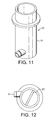
- Figure 11 is a perspective view of an upper part of the device according to a fourth embodiment.
- Figure 12 is a cross sectional view of the part of device of Figure 11 ;
- Figure 13 is a longitudinal view along line B-B of Figure 12 ;
- Figure 14 is a longitudinal view along line A-A of Figure 12 ;
- Figure 15 is a perspective view of the bottom part of the device of Figure 11 ;
- Figure 16 is a bottom view of the bottom part of Figure 15 ;
- Figure 17 is a side view of the bottom part of Figure 15 ;
- Figure 18 is a cross section view of the bottom part along line A-A of Figure 16 ;
- Figure 19 is an inner view of the bottom part of Figure 15 .
- a beverage production apparatus 1 that includes a device 2 of the invention for producing a frothed liquid from ingredient and a diluent entering the device.
- the device of the invention will be called “mixing and frothing device” or simply “device” in the rest of the description.
- the beverage production apparatus comprises a reservoir of soluble ingredient 3 placed above the device which is coupled with a dosing system 4.
- the dosing system has the primary function to meter upon request doses of ingredient into the mixing and frothing device.
- the reservoir can be a hopper which is permanent or a disposable package containing the soluble ingredient.
- the dosing system can be any suitable system such as a dosing screw or a reciprocating dosing piston.
- the dosing technology is also of course dependent on the nature of the soluble ingredient.
- the soluble ingredient is typically a dry food powder. However, it could also be a liquid concentrate.
- the device is fed upon request with ingredient manually or automatically as prompted by a controller 11 and command 12.
- the reservoir and dosing system are optional in the apparatus. Therefore, the device could be fed manually using a scoop, for instance.
- a diluent feed circuit is provided in the apparatus to be able to feed the mixing and frothing device 2 with diluent, more particularly, hot water.
- a water reservoir 5 is provided that can be replenished with fresh water.
- a water pump 6 transports the diluent from the reservoir 5 to a water heating system 7 such as a thermoblock or a cartridge type heater and to eventually a non-return valve 8.
- the pump can be any type of pump such as a piston pump, diaphragm pump or a peristaltic pump.
- water is fed into the device by a tube means 9.
- the mixing and frothing device can be placed directly above a service tray 10 onto which is placed a receptacle to receive the frothed liquid.
- a controller 11 can be further provided to coordinate dosing of the soluble ingredient by the dosing system 4 and diluent by the pump 6 upon the user actuating or being prompted to press a command 12 on the apparatus.
- the device comprises a chamber 13 which is demarcated by a bottom wall 14 and a side wall 15 extending upwardly and terminating by a flange wall 16 ensuring mechanical gripping in the apparatus and surrounding a large upper central opening 17.
- the central opening 17 allows the chamber to be fed with soluble ingredient being dropped in either by the dosing system of the beverage production apparatus or manually by a metering utensil.
- the surface of the upward wall 15 is preferably smooth and relatively vertical although a slight inclination relative to vertical is conceivable.
- the central opening 17 also serves as an air inlet for allowing air to enter the chamber and mix with the frothed liquid being created.
- the chamber can have diameter of from about 15 to 40 mm, more preferably of from 20 to 31 mm.
- a chamber which has a diameter-to-height ratio comprised between 1:2 and 1:10, most preferably, between 1:2.5 and 1:5, wherein the height is the distance "f" of the upward wall.
- Diluent is fed at relatively high velocity into the chamber by a diluent inlet 18.
- the diluent inlet is placed through the upward wall 15.
- the inlet is sized and oriented in a manner to promote both centrifugal circulation of the liquid and shearing on the surfaces of the liquid. The result is a liquid being frothed in a short amount of time.
- the inlet 18 forms a nozzle of small diameter enabling to create a jet with high linear velocity in the chamber.
- the diameter "a" of the inlet ranges of from 0.3 to 0.8 mm, most preferably between 0.35 and 0.55 mm.
- the flow rate is preferably of from 1.5 to 5 mL/s, most preferably of about 2 to 4.5 mL/s.
- Such flow conditions and size of the nozzle are able to produce a linear velocity in the order of from 10 to 50 m/sec, most preferably of from 12 to 25 m/sec., for example, of about 18 m/sec.
- the diluent inlet is so oriented in a direction that is offset relative to the longitudinal median axis O of the chamber. More precisely, the direction of the inlet is such that the ratio d/r is comprised between 0.2 and 0.9; where "d” is the orthogonal distance separating the direction of the inlet from the centre axis and “r” is the radius of the chamber at the horizontal level of the inlet ( Figure 3 ).
- the vertical position of the diluent inlet 18 can also be important to ensure a proper distance between it and the liquid.
- a preferred vertical position "c" of the diluent inlet from the inner edge of the bottom wall is comprised between about 5 and 20 mm, most preferably between 6 to 15 mm.
- the diluent inlet is also positioned preferably at a relatively low position relative to the longitudinal dimension "f" of the upward wall 15 so that splashing of liquid or overflow of liquid out of the chamber due the liquid rising up along the surface of wall by the dynamic of the flow, i.e., a centrifugal effect, is prevented.
- the diluent inlet is situated at a distance closer to the base of the bottom wall than to the aperture 17. More preferably, the inlet is situated at about or within in the lower quarter of the chamber (as measured by the height "f" of the upward wall 15).
- the bottom wall 14 of the chamber comprises means for controlling the delivered flow of the frothed liquid through the device.
- the general principle lies in that liquid is prevented from too quickly leaving the chamber in order to be able to create a layer of liquid that rises up along the side of the upward wall 15 that can be impacted by the jet of diluent and consequently for creating a high amount of shear.
- Figure 2 materializes, for example, the surfaces 19 of the liquid in circulation due to the centrifugal effect promoted by the jet on the liquid in the chamber.
- the flow control means are therefore obtained by a control of the size and configuration of the delivery outlet(s).
- a single liquid outlet 20 is configured in the bottom wall.
- the surface area of the single outlet is preferably comprised between 0.8 and 12.6 mm 2 .
- a plurality of outlets 21 are provided, preferably, between 2 and 15, most preferably between 5 and 10, with an individual surface area of each outlet comprised between about 0.28 and 1.5 mm 2 .
- Rinsing of the chamber may be carried out by diluent being sent via the nozzle in the chamber either continuously or intermittently, e.g., by pulsing diluent in the chamber.
- the shape of the bottom wall 14 can be conical so that spreading of the layer of liquid is promoted.
- the angle 'j" of the cone of the bottom wall, relative to a plane transversal to O, can vary of from 1 to 45 degrees.
- the bottom wall could be rounded or flat as well.
- FIG. 4 shows the presence of a baffle 22 in chamber whose function is primarily to break the circulating flow of the liquid in the chamber above the diluent inlet. As a result, the liquid is prevented from flowing over the chamber through the upper air and dosing opening 17.
- the baffle can be a single wall crossing the chamber as illustrated.
- the baffle forms a wall positioned substantially parallel or aligned with the longitudinal axis O.
- the baffle is substantially vertical in a normal use of the device.
- the dimension of the baffle depends on the geometry and size of the chamber.
- the baffle has a height H of from 10 to 30 mm, a length equal to the diameter of the chamber, for instance, of from 20 and 31 mm and a thickness of from about 1 to 2 mm.
- a vertical baffle as represented provided good results with powder having a relatively low ability to stick to walls of the device in humid conditions such as agglomerated powder of coffee or milk. With non-agglomerated powder, less good results were noticed because some powder would tend to stick to the baffle when falling into the device.
- FIGS 7 and 8 show a mode in which the baffle means is divided into a plurality of baffles, e.g., four baffles 23 distributed in the upward wall.
- the baffles are portions of walls running substantially parallel to the longitudinal axis which extend radially only partially across the chamber leaving a central passage 24.
- the baffles extend a transversal projected distance from the inner surface of the chamber which is between 0.1 to 0.5 the value of the radius of the chamber. Therefore, a central passage 24 is provided which benefit is that powder can be dosed in the centre of the chamber from the dosing opening 17 while limiting the chance for the powder to stick on the surfaces of the baffle when falling by gravity in the device.
- the baffles have a height H of from 10 to 30 mm and a length L of about 5 mm to half the internal diameter "e" of the chamber.
- the baffles can be in a number of from 2 to 6 evenly and radially distributed in the chamber from the wall 15. In the figure, four baffles are provided which are evenly spaced at 90 degrees.
- FIGS 9 and 10 show another variant with baffles 23 forming portions of walls inclined relatively to the longitudinal central axis O.
- the baffles are inclined relative to the horizontal and their free ends 28 are directed in the direction of the opening 17 or upwardly.
- the baffle can extend inwardly of a distance between a value of about 5 mm and the value of the radius of the chamber.
- the baffles extend a transversal projected distance L from the inner surface of the chamber which is between 0.1 to 0.5 time the value of the radius of the chamber.
- the baffles can also be oriented in transversal inclination in a manner that their side edges 26, 27 are at different heights relative to each other. In an alternative, the side edges 26, 27 could be at the same height relative to each other. In particular good results were obtained with non-agglomerated powder of coffee or coffee mixes.
- the baffles can cross each other while leaving certain gaps for air and powder to enter the chamber from air and dosing opening 17.
- baffles could take various shapes that significantly differ from portions of flat walls. They could be pins, needles, a grid or portions of grid or curved walls, an helical wall or annular wall or a star shaped wall.
- Figures 11 to 19 illustrate a possible construction of the device of the invention in two assembled parts.
- a first upper part 30 is illustrated by Figures 11 to 14 .
- a second lower part 40 is illustrated by Figures 15 to 19 .
- the two parts can be produced by plastic injection moulding and assembled by press-fitting, with or without a sealing member in-between, or be eventually welded or glued for providing a liquid tight assembly.
- the upper part takes a single piece of tubular shape forming the upward wall 15 of the device.
- the diluent inlet 18 extends from the upward wall by a connection portion 31 enabling an easy and rapid coupling with the diluent flexible line of the beverage production apparatus 1 of Figure 1 .
- a baffle 22 can be provided in the chamber that is also moulded as one integral piece with the tubular upper portion 30.
- a press-fit type connection 32 such as annular inner groove.
- the connection 32 is so designed to complementary fit a complementary press-fitting connection of the lower part 40 of the device as shown in Figures 15 to 19 .
- the lower part 40 forms the conical bottom wall and an outlet portion 41 of the device.
- the outlet portion can be formed as a tubular portion of reduced section that extends from the centre of the conical wall for guiding the flow of liquid exiting the device.
- a plurality of small wings 42 converging to the inner centre of the wall can be made to slow down the speed of the liquid before it exists through the outlet portion.
- a series of small outlets 43 are distributed along a small circular path just around the centre of the bottom wall.
- the outlets, for instance eight outlets, are preferably located no more than a distance of about 0.5 mm from the centre between each of the small wings.
- the diameter of each outlet is of about 0.8 to 1.1 mm.
- a small resilient flange 44 extends upwards to form with a locking protrusion of the complementary press-fitting connection of the device.
- This lower part can be moulded in plastic and press fitted directly to the upper part to form the device of the invention.
- the operation of the beverage production apparatus of the invention can be described in an example that follows.
- a user presses a button of command 12 to activate the apparatus.
- the controller 11 receives the order from the command 12 and drives the dosing unit 4 according to the choice made by the user.
- the dosing unit will meter a certain amount of soluble ingredient from the reservoir 3; such amount being delivered in the frothing device of the invention through its upper opening.
- the soluble ingredient can be agglomerated or non-agglomerated coffee powder for instance.
- the powder falls by gravity in the bottom of the chamber, preferably, right through the central passage between the baffles in particular when powder has a tendency to stick to walls or baffles (e.g., non-agglomerated coffee powder).
- the controller 6 turns the pump on and eventually the heater too if hot water is required. Water mixes with the powder and frothed liquid is so produced. Water can be dosed in a volume of between 25 to 250 mL. Preferably, for small coffees, 25 or 40 mL of water is dosed in one continuous jet. The controller can stop the pump at regular intervals to let the frothed liquid drain, in particular, for larger volumes. Then, the controller turns the pump off. If necessary, the controller further turns the pump on again for delivering a small rinsing water volume to provide the rinsing step. In an alternative, the rinsing step is carried out continuously by a single jet when producing the frothed liquid.
- One advantage of the invention is the ability to provide a high quality frothed liquid such as coffee with a thick and homogeneous crema using soluble ingredient as starting material and which is comparable in quality to roast-and-ground coffee beverages such as espresso or lungo.
- the invention does not have the disadvantages of leaving solid residue in the device or cartridge, nor it has the one of generating potential packaging waste.
- the invention is of convenient use because it can be automated easily and can serve both for a use in small beverage appliances or in high throughput beverage production devices such as "barista" type machines.
Priority Applications (30)
| Application Number | Priority Date | Filing Date | Title |
|---|---|---|---|
| EP20060125772 EP1932457A1 (de) | 2006-12-11 | 2006-12-11 | Gerät und Verfahren zur Herstellung einer schäumenden Flüssigkeit aus löslichen Inhaltstoffen und Verdünnungsmittel |
| AU2007332588A AU2007332588B2 (en) | 2006-12-11 | 2007-12-06 | Device and method for producing a frothed liquid from soluble ingredients and diluent |
| EP13168172.8A EP2653080B1 (de) | 2006-12-11 | 2007-12-06 | Gerät und Verfahren zur Herstellung einer schäumenden Flüssigkeit aus löslichen Inhaltstoffen und Verdünnungsmittel |
| EP20130168206 EP2653081B1 (de) | 2006-12-11 | 2007-12-06 | Gerät zur Herstellung einer schäumenden Flüssigkeit aus löslichen Inhaltstoffen und Verdünnungsmittel |
| EP07847879.9A EP2091393B1 (de) | 2006-12-11 | 2007-12-06 | Vorrichtung und verfahren zur herstellung einer aufgeschäumten flüssigkeit aus löslichen zutaten und verdünnungsmittel |
| ES15157833.3T ES2673879T3 (es) | 2006-12-11 | 2007-12-06 | Dispositivo y método para producir un líquido espumoso a partir de ingredientes solubles y diluyente |
| MX2013014017A MX355514B (es) | 2006-12-11 | 2007-12-06 | Dispositivo y método para producir un líquido espumoso de ingredientes solubles y diluyente. |
| EP15157833.3A EP2907428B1 (de) | 2006-12-11 | 2007-12-06 | Gerät zur Herstellung einer schäumenden Flüssigkeit aus löslichen Inhaltstoffen und Verdünnungsmittel |
| PL07847879T PL2091393T3 (pl) | 2006-12-11 | 2007-12-06 | Sposób i urządzenie do wytwarzania spienionej cieczy z rozpuszczalnych składników i rozcieńczalnika |
| PCT/EP2007/063391 WO2008071613A1 (en) | 2006-12-11 | 2007-12-06 | Device and method for producing a frothed liquid from soluble ingredients and diluent |
| US12/518,675 US8960079B2 (en) | 2006-12-11 | 2007-12-06 | Device and method for producing a frothed liquid from soluble ingredients and diluent |
| JP2009540723A JP5422391B2 (ja) | 2006-12-11 | 2007-12-06 | 可溶性原料および希釈剤から発泡液を製造するための装置および方法 |
| RU2009126593/12A RU2462977C2 (ru) | 2006-12-11 | 2007-12-06 | Способ приготовления вспененной жидкости из растворимых ингредиентов и растворителя и устройство для его осуществления |
| ES07847879T ES2430293T3 (es) | 2006-12-11 | 2007-12-06 | Dispositivo y procedimiento para la producción de un líquido con espuma a partir de ingredientes solubles y un diluyente |
| MX2013014018A MX355516B (es) | 2006-12-11 | 2007-12-06 | Dispositivo y método para producir un líquido espumoso de ingredientes solubles y diluyente. |
| CN2007800507809A CN101600378B (zh) | 2006-12-11 | 2007-12-06 | 由可溶配料和稀释剂生产泡沫液体的装置和方法 |
| MYPI20092368A MY162226A (en) | 2006-12-11 | 2007-12-06 | Device and method for producing a frothed liquid from soluble ingredients and diluent |
| EP20130168167 EP2653407B1 (de) | 2006-12-11 | 2007-12-06 | Gerät zur Herstellung einer schäumenden Flüssigkeit aus löslichen Inhaltstoffen und Verdünnungsmittel |
| MX2009006128A MX2009006128A (es) | 2006-12-11 | 2007-12-06 | Dispositivo y metodo para producir un liquido espumoso de ingredientes solubles y diluyente. |
| ES13168206.4T ES2545199T3 (es) | 2006-12-11 | 2007-12-06 | Dispositivo para producir un líquido espumoso a partir de ingredientes solubles y diluyente |
| CA2673279A CA2673279C (en) | 2006-12-11 | 2007-12-06 | Device and method for producing a frothed liquid from soluble ingredients and diluent |
| CL2007003578A CL2007003578A1 (es) | 2006-12-11 | 2007-12-10 | Dispositivo para producir un liquido espumante que comprende una camara, a lo menos una entrada de diluyente y a lo menos una salida de diluyente, donde la entrada es provista a traves de una pared ascendente dimensionada y orientada para dirigir un chorro de diluyente en la camara; y metodo para producir un liquido espumante. |
| PE2007001759A PE20081619A1 (es) | 2006-12-11 | 2007-12-10 | Dispositivo y metodo para disolver un polvo y producir un liquido espumoso desde ingredientes solubles y un diluyente |
| UY30777A UY30777A1 (es) | 2006-12-11 | 2007-12-11 | Dispositivo y método para disolver un polvo y producir un liquido espumoso desde ingredientes solubles y un diluyente |
| ARP070105549 AR064290A1 (es) | 2006-12-11 | 2007-12-11 | Dispositivo y metodo para disolver un polvo y producir un liquido espumoso desde ingredientes solubles y un diluyente |
| TW96147307A TWI459921B (zh) | 2006-12-11 | 2007-12-11 | 用於由可溶性組分及稀釋劑製造泡沫液體之裝置及方法 |
| ZA200904862A ZA200904862B (en) | 2006-12-11 | 2009-07-10 | Device and method for producing a frothed liquid from soluble ingredients and diluent |
| AU2014274521A AU2014274521B2 (en) | 2006-12-11 | 2014-12-09 | Device and method for producing a frothed liquid from soluble ingredients and diluent |
| US14/588,764 US9408495B2 (en) | 2006-12-11 | 2015-01-02 | Device and method for producing a frothed liquid from soluble ingredients and diluent |
| US14/601,823 US9307859B2 (en) | 2006-12-11 | 2015-01-21 | Device and method for producing a frothed liquid from soluble ingredients and diluent |
Applications Claiming Priority (1)
| Application Number | Priority Date | Filing Date | Title |
|---|---|---|---|
| EP20060125772 EP1932457A1 (de) | 2006-12-11 | 2006-12-11 | Gerät und Verfahren zur Herstellung einer schäumenden Flüssigkeit aus löslichen Inhaltstoffen und Verdünnungsmittel |
Publications (1)
| Publication Number | Publication Date |
|---|---|
| EP1932457A1 true EP1932457A1 (de) | 2008-06-18 |
Family
ID=37983520
Family Applications (6)
| Application Number | Title | Priority Date | Filing Date |
|---|---|---|---|
| EP20060125772 Withdrawn EP1932457A1 (de) | 2006-12-11 | 2006-12-11 | Gerät und Verfahren zur Herstellung einer schäumenden Flüssigkeit aus löslichen Inhaltstoffen und Verdünnungsmittel |
| EP07847879.9A Revoked EP2091393B1 (de) | 2006-12-11 | 2007-12-06 | Vorrichtung und verfahren zur herstellung einer aufgeschäumten flüssigkeit aus löslichen zutaten und verdünnungsmittel |
| EP13168172.8A Not-in-force EP2653080B1 (de) | 2006-12-11 | 2007-12-06 | Gerät und Verfahren zur Herstellung einer schäumenden Flüssigkeit aus löslichen Inhaltstoffen und Verdünnungsmittel |
| EP20130168206 Not-in-force EP2653081B1 (de) | 2006-12-11 | 2007-12-06 | Gerät zur Herstellung einer schäumenden Flüssigkeit aus löslichen Inhaltstoffen und Verdünnungsmittel |
| EP20130168167 Not-in-force EP2653407B1 (de) | 2006-12-11 | 2007-12-06 | Gerät zur Herstellung einer schäumenden Flüssigkeit aus löslichen Inhaltstoffen und Verdünnungsmittel |
| EP15157833.3A Active EP2907428B1 (de) | 2006-12-11 | 2007-12-06 | Gerät zur Herstellung einer schäumenden Flüssigkeit aus löslichen Inhaltstoffen und Verdünnungsmittel |
Family Applications After (5)
| Application Number | Title | Priority Date | Filing Date |
|---|---|---|---|
| EP07847879.9A Revoked EP2091393B1 (de) | 2006-12-11 | 2007-12-06 | Vorrichtung und verfahren zur herstellung einer aufgeschäumten flüssigkeit aus löslichen zutaten und verdünnungsmittel |
| EP13168172.8A Not-in-force EP2653080B1 (de) | 2006-12-11 | 2007-12-06 | Gerät und Verfahren zur Herstellung einer schäumenden Flüssigkeit aus löslichen Inhaltstoffen und Verdünnungsmittel |
| EP20130168206 Not-in-force EP2653081B1 (de) | 2006-12-11 | 2007-12-06 | Gerät zur Herstellung einer schäumenden Flüssigkeit aus löslichen Inhaltstoffen und Verdünnungsmittel |
| EP20130168167 Not-in-force EP2653407B1 (de) | 2006-12-11 | 2007-12-06 | Gerät zur Herstellung einer schäumenden Flüssigkeit aus löslichen Inhaltstoffen und Verdünnungsmittel |
| EP15157833.3A Active EP2907428B1 (de) | 2006-12-11 | 2007-12-06 | Gerät zur Herstellung einer schäumenden Flüssigkeit aus löslichen Inhaltstoffen und Verdünnungsmittel |
Country Status (18)
| Country | Link |
|---|---|
| US (3) | US8960079B2 (de) |
| EP (6) | EP1932457A1 (de) |
| JP (1) | JP5422391B2 (de) |
| CN (1) | CN101600378B (de) |
| AR (1) | AR064290A1 (de) |
| AU (1) | AU2007332588B2 (de) |
| CA (1) | CA2673279C (de) |
| CL (1) | CL2007003578A1 (de) |
| ES (3) | ES2545199T3 (de) |
| MX (3) | MX355516B (de) |
| MY (1) | MY162226A (de) |
| PE (1) | PE20081619A1 (de) |
| PL (1) | PL2091393T3 (de) |
| RU (1) | RU2462977C2 (de) |
| TW (1) | TWI459921B (de) |
| UY (1) | UY30777A1 (de) |
| WO (1) | WO2008071613A1 (de) |
| ZA (1) | ZA200904862B (de) |
Cited By (9)
| Publication number | Priority date | Publication date | Assignee | Title |
|---|---|---|---|---|
| EP2127567A1 (de) | 2008-05-28 | 2009-12-02 | Nestec S.A. | Gerät und Verfahren zur Herstellung von aufgeschäumten geweissten Getränken |
| US8043645B2 (en) | 2008-07-09 | 2011-10-25 | Starbucks Corporation | Method of making beverages with enhanced flavors and aromas |
| WO2014006325A1 (fr) * | 2012-07-05 | 2014-01-09 | Seb S.A. | Dispositif de preparation d'une boisson moussee et machine equipee d'un tel dispositif |
| WO2014206868A1 (en) * | 2013-06-26 | 2014-12-31 | Nestec S.A. | Mixing chamber for producing beverages |
| US9307859B2 (en) | 2006-12-11 | 2016-04-12 | Nestec S.A. | Device and method for producing a frothed liquid from soluble ingredients and diluent |
| WO2017045876A1 (en) * | 2015-09-15 | 2017-03-23 | Nestec S.A. | Beverage preparation machine |
| CN107207236A (zh) * | 2015-03-03 | 2017-09-26 | 富士电机株式会社 | 乳饮料供给装置 |
| EP3620086A1 (de) * | 2018-09-07 | 2020-03-11 | Quickjuice, S.L. | Kapselvorrichtung zur zubereitung von säften |
| WO2020058448A1 (en) * | 2018-09-20 | 2020-03-26 | Société des Produits Nestlé S.A. | Beverage apparatus with mixing chamber |
Families Citing this family (43)
| Publication number | Priority date | Publication date | Assignee | Title |
|---|---|---|---|---|
| EP2127568A1 (de) * | 2008-05-29 | 2009-12-02 | Nestec S.A. | Misch- und Ausgabevorrichtung mit beweglicher Mischkammer |
| EP2168468B1 (de) | 2008-09-24 | 2011-04-06 | Nestec S.A. | Vorrichtung zur Zubereitung eines Getränks in einer Tasse |
| US20110000861A1 (en) * | 2009-07-06 | 2011-01-06 | Bear Creek Services, LLC. | Portable and Scalable Water Reclamation System and Method |
| EA025023B1 (ru) | 2010-07-14 | 2016-11-30 | Юнилевер Нв | Способ заваривания напитка и картридж, содержащий заварочный материал |
| AU2011278539B2 (en) * | 2010-07-14 | 2014-04-03 | Ekaterra Research and Development UK Limited | Beverage brewing apparatus and method |
| KR200457227Y1 (ko) * | 2010-12-17 | 2011-12-09 | 컨벡스코리아(주) | 에스프레소 커피머신의 거품발생부재 |
| CN102389261B (zh) * | 2011-01-13 | 2014-11-05 | 九阳股份有限公司 | 制备饮品的设备及其制备方法 |
| JP5937671B2 (ja) | 2011-03-30 | 2016-06-22 | ネステク ソシエテ アノニム | 改善されたノズルアセンブリを有する飲料ディスペンサ |
| CN113080706A (zh) * | 2011-05-10 | 2021-07-09 | 布瑞威利私人有限公司 | 咖啡制备设备 |
| ITTO20110478A1 (it) * | 2011-05-31 | 2012-12-01 | Lavazza Luigi Spa | Capsula, macchina, sistema e procedimento per la preparazione di bevande, in particolare di caffe' espresso |
| WO2013101033A1 (en) | 2011-12-29 | 2013-07-04 | Nestec S.A. | Dispenser for producing beverages by dissolution of a soluble ingredient |
| MY168576A (en) | 2012-02-09 | 2018-11-14 | Keurig Green Mountain Inc | Beverage forming device with beverage outlet control |
| EP2682029B1 (de) | 2012-07-05 | 2015-04-29 | Nestec S.A. | Getränkeherstellungsmaschine mit beweglicher Mischkammer |
| AU2013329853A1 (en) * | 2012-10-09 | 2015-04-23 | Nestec S.A. | Beverage machine |
| WO2014132392A1 (ja) * | 2013-02-28 | 2014-09-04 | パイオニア株式会社 | 積層体の製造方法 |
| JP6460635B2 (ja) * | 2014-03-24 | 2019-01-30 | シャープ株式会社 | 混合物生成装置 |
| EP3157396B1 (de) * | 2014-06-20 | 2018-07-25 | Nestec S.A. | Getränkeherstellungsmaschine mit wiederauffüllbarem mehrfachdosierungsbehälter |
| WO2016014568A1 (en) * | 2014-07-21 | 2016-01-28 | Abbott Laboratories | Pod with built-in inlet fluid ports to increase mixing |
| ES2683872T3 (es) * | 2014-07-21 | 2018-09-28 | Abbott Laboratories | Cápsula con boquilla rociadora y procedimiento de uso |
| WO2016096530A1 (en) * | 2014-12-16 | 2016-06-23 | Nestec S.A. | Beverage dispenser |
| KR101909408B1 (ko) | 2015-03-20 | 2018-10-17 | 란실리오 그룹 에스.피.에이. | 발포 장치 및 발포 방법 |
| CA2981914A1 (en) | 2015-04-21 | 2016-10-27 | Nestec S.A. | Beverage dispenser for preparing layered beverages |
| JP6620429B2 (ja) * | 2015-06-02 | 2019-12-18 | 富士電機株式会社 | 飲料ディスペンサ |
| US10258191B2 (en) | 2015-09-18 | 2019-04-16 | Starbucks Corporation | Beverage dispensing systems and methods |
| US10531761B2 (en) | 2015-09-18 | 2020-01-14 | Starbucks Corporation | Beverage preparation systems and methods |
| US20180317699A1 (en) * | 2015-10-15 | 2018-11-08 | Nestec S.A. | Beverage preparation machine |
| RU2612400C1 (ru) * | 2015-11-10 | 2017-03-09 | Акционерное общество "Новомет-Пермь" | Устройство для подачи ингибитора |
| ES2760956T3 (es) * | 2015-11-13 | 2020-05-18 | Nestle Sa | Dispositivo de espumado |
| US11160412B2 (en) | 2016-05-17 | 2021-11-02 | Societe Des Produits Nestle S.A. | Beverage preparation device |
| US10966563B2 (en) | 2016-11-16 | 2021-04-06 | Societe Des Produits Nestle S.A. | Beverage preparation apparatus comprising a mixing chamber |
| EP3342319A1 (de) | 2016-12-30 | 2018-07-04 | Nestec S.A. | Maschine zur zubereitung von getränken aus schüttgut und wasser |
| CN108567332A (zh) * | 2017-03-08 | 2018-09-25 | 何宜佶 | 饮料制备系统 |
| ES2897073T3 (es) | 2017-07-18 | 2022-02-28 | Nestle Sa | Dispositivo de medición y distribución de material a granel |
| WO2019052888A1 (en) | 2017-09-13 | 2019-03-21 | Nestec S.A. | DRINK DISPENSER |
| CN111465337B (zh) * | 2017-12-21 | 2023-01-24 | 雀巢产品有限公司 | 包括混合室的饮料制备装置 |
| EP3501347A1 (de) | 2017-12-22 | 2019-06-26 | Nestec S.A. | Getränkespender mit mehreren auflösungskammern |
| US11490760B2 (en) | 2017-12-22 | 2022-11-08 | Societe Des Produits Nestle S.A. | Beverage dispenser with a plurality of dissolution chambers |
| JP6697505B2 (ja) * | 2018-04-25 | 2020-05-20 | シャープ株式会社 | 混合物生成装置 |
| WO2020001855A1 (en) | 2018-06-26 | 2020-01-02 | Societe Des Produits Nestle S.A. | Beverage preparation machine with refillable multi-dose container |
| EP3826517B1 (de) * | 2018-07-24 | 2022-08-31 | Société des Produits Nestlé S.A. | Getränkezubereitungsverfahren |
| JP2022521547A (ja) | 2019-02-25 | 2022-04-08 | ソシエテ・デ・プロデュイ・ネスレ・エス・アー | 低温飲料注出システム |
| CN113660890B (zh) | 2019-04-04 | 2024-04-02 | 雀巢产品有限公司 | 具有粉末容器的饮料分配器 |
| US20220279958A1 (en) | 2019-07-29 | 2022-09-08 | Societe Des Produits Nestle S.A. | Method for preparing milk and coffee based beverages |
Citations (4)
| Publication number | Priority date | Publication date | Assignee | Title |
|---|---|---|---|---|
| US3446399A (en) * | 1967-06-09 | 1969-05-27 | Umc Ind | Dispensing apparatus |
| US4493249A (en) * | 1982-11-12 | 1985-01-15 | Bunn-O-Matic Corporation | Apparatus for dissolving soluble coffee |
| US4859072A (en) * | 1987-09-03 | 1989-08-22 | Matra-Werke Gmbh | Device for the continuous production of a liquid mixture of solids and liquids |
| EP0885580A1 (de) * | 1997-06-17 | 1998-12-23 | Premark International Holdings B.V. | Vorrichtung zum Bereiten und Ausgeben von Getränken für voll- oder halbautomatische Verkaufsautomaten |
Family Cites Families (34)
| Publication number | Priority date | Publication date | Assignee | Title |
|---|---|---|---|---|
| US2522102A (en) * | 1947-10-07 | 1950-09-12 | William C Dold | Infusion apparatus |
| US3212757A (en) * | 1963-01-07 | 1965-10-19 | Martin Ernest Newell | Mixing and aerating apparatus |
| US3300094A (en) * | 1965-11-23 | 1967-01-24 | Rock Ola Mfg Corp | Mixing device |
| DE1654978A1 (de) * | 1967-12-27 | 1971-04-01 | Koch Walter | Maschine zur Zubereitung waehlbar bestimmter Mengen von Trinkkaffee aus Kaffeepulver und Heisswasser |
| US3844447A (en) * | 1971-08-17 | 1974-10-29 | Servomat Fast Foods Pty Ltd | Vending machines |
| US3782695A (en) * | 1972-07-10 | 1974-01-01 | Union Oil Co | Apparatus and method for dispersing solid particles in a liquid |
| US4193552A (en) * | 1977-10-20 | 1980-03-18 | Ishikawa Ken Ichi | Liquid sprayer pipe with inclined slits |
| US4193511A (en) | 1978-05-12 | 1980-03-18 | Taber Gilbert L | Apparatus for manual manipulation of articles |
| US4193522A (en) * | 1978-07-27 | 1980-03-18 | The Cornelius Company | Dispensing machine mixing device and housing therefor |
| JPS58723U (ja) * | 1981-06-23 | 1983-01-06 | 東芝機械株式会社 | 飲料供給装置 |
| US4921712A (en) * | 1988-08-19 | 1990-05-01 | Malmquist Neil A | Automatic low volume beverage brewing system |
| US4978833A (en) * | 1989-01-27 | 1990-12-18 | Bunn-O-Matic Corporation | Hot water dispenser having improved water temperature control system |
| GB9007133D0 (en) * | 1990-03-30 | 1990-05-30 | Gen Foods Kraft Ltd | Comestibles containing packages |
| JPH0548085A (ja) | 1991-08-20 | 1993-02-26 | Matsushita Electric Works Ltd | 半導体装置の製造方法 |
| JP2568469Y2 (ja) * | 1991-11-29 | 1998-04-15 | 東芝機器株式会社 | 飲料ミキシング装置 |
| US5588557A (en) * | 1995-05-19 | 1996-12-31 | Topar; William M. | Beverage dispenser |
| JP3052198B2 (ja) * | 1998-05-18 | 2000-06-12 | 信二 草間 | 自動抹茶立て装置 |
| US6267496B1 (en) * | 1998-12-03 | 2001-07-31 | Bryan Real | Beverage supply apparatus for dispensing machine |
| US6155158A (en) * | 1999-10-12 | 2000-12-05 | Bunn-O-Matic Corporation | Beverage brewing system |
| NL1016106C2 (nl) | 2000-09-05 | 2002-03-07 | Sara Lee De Nv | Inrichting voor het bereiden van een koffie-extract met een kleinbellige schuimlaag. |
| EP2241229B8 (de) | 2001-04-27 | 2012-07-25 | Mars, Incorporated | Vorrichtung zur Herstellung von geschäumten Getränken |
| NL1018248C2 (nl) | 2001-06-08 | 2002-12-10 | Sara Lee De Nv | Inrichting en werkwijze voor het bereiden van een voor consumptie geschikte, geschuimde drank. |
| US6698625B2 (en) | 2002-02-11 | 2004-03-02 | Nestec S.A. | Mixing and frothing device and method |
| NL1020837C2 (nl) * | 2002-06-12 | 2003-12-15 | Sara Lee De Nv | Inrichting en werkwijze voor het bereiden van koffie met een fijnbellige schuimlaag, in het bijzonder cappuccino. |
| US6889603B2 (en) * | 2002-12-24 | 2005-05-10 | Nestec S.A. | Clean-in-place automated food or beverage dispenser |
| EP1510159A1 (de) * | 2003-08-25 | 2005-03-02 | Nestec S.A. | Verfahren zur Herstellung eines Lebensmittels |
| RU39260U1 (ru) * | 2004-03-01 | 2004-07-27 | Ребряков Евгений Михайлович | Устройство для вспенивания растворов и насыщения их газом |
| US7226631B2 (en) * | 2004-08-12 | 2007-06-05 | Nestec S.A. | Method and apparatus for consumable powder reconstitution and frothing |
| ATE377371T1 (de) | 2004-09-27 | 2007-11-15 | Nestec Sa | Mischeinrichtung, kaffeemaschine mit solcher mischeinrichtung und anwendung solcher mischeinrichtung |
| NL1029155C2 (nl) | 2004-10-19 | 2006-04-20 | Sara Lee De Nv | Systeem en werkwijze voor het bereiden van een voor consumptie geschikte drank. |
| RU2387360C2 (ru) * | 2005-04-11 | 2010-04-27 | Старбакс Корпорейшн | Машина и способ для приготовления напитка, такого как кофе |
| WO2007027206A2 (en) * | 2005-04-11 | 2007-03-08 | Coffee Equipment Company | Machine for brewing a beverage such as coffee and related method |
| DE202006008409U1 (de) * | 2006-05-27 | 2006-08-10 | Eugster/Frismag Ag | Einrichtung zum selbsttätigen Auflösen von Instantpulver, insbesondere Milchpulver, in heißem Wasser und insbesondere zum Aufschäumen |
| EP1932457A1 (de) | 2006-12-11 | 2008-06-18 | Nestec S.A. | Gerät und Verfahren zur Herstellung einer schäumenden Flüssigkeit aus löslichen Inhaltstoffen und Verdünnungsmittel |
-
2006
- 2006-12-11 EP EP20060125772 patent/EP1932457A1/de not_active Withdrawn
-
2007
- 2007-12-06 US US12/518,675 patent/US8960079B2/en active Active
- 2007-12-06 EP EP07847879.9A patent/EP2091393B1/de not_active Revoked
- 2007-12-06 MY MYPI20092368A patent/MY162226A/en unknown
- 2007-12-06 MX MX2013014018A patent/MX355516B/es unknown
- 2007-12-06 ES ES13168206.4T patent/ES2545199T3/es active Active
- 2007-12-06 EP EP13168172.8A patent/EP2653080B1/de not_active Not-in-force
- 2007-12-06 EP EP20130168206 patent/EP2653081B1/de not_active Not-in-force
- 2007-12-06 MX MX2009006128A patent/MX2009006128A/es active IP Right Grant
- 2007-12-06 MX MX2013014017A patent/MX355514B/es unknown
- 2007-12-06 PL PL07847879T patent/PL2091393T3/pl unknown
- 2007-12-06 AU AU2007332588A patent/AU2007332588B2/en not_active Ceased
- 2007-12-06 JP JP2009540723A patent/JP5422391B2/ja active Active
- 2007-12-06 CN CN2007800507809A patent/CN101600378B/zh active Active
- 2007-12-06 ES ES15157833.3T patent/ES2673879T3/es active Active
- 2007-12-06 CA CA2673279A patent/CA2673279C/en not_active Expired - Fee Related
- 2007-12-06 RU RU2009126593/12A patent/RU2462977C2/ru active
- 2007-12-06 EP EP20130168167 patent/EP2653407B1/de not_active Not-in-force
- 2007-12-06 ES ES07847879T patent/ES2430293T3/es active Active
- 2007-12-06 WO PCT/EP2007/063391 patent/WO2008071613A1/en active Application Filing
- 2007-12-06 EP EP15157833.3A patent/EP2907428B1/de active Active
- 2007-12-10 PE PE2007001759A patent/PE20081619A1/es not_active Application Discontinuation
- 2007-12-10 CL CL2007003578A patent/CL2007003578A1/es unknown
- 2007-12-11 AR ARP070105549 patent/AR064290A1/es unknown
- 2007-12-11 TW TW96147307A patent/TWI459921B/zh not_active IP Right Cessation
- 2007-12-11 UY UY30777A patent/UY30777A1/es unknown
-
2009
- 2009-07-10 ZA ZA200904862A patent/ZA200904862B/xx unknown
-
2015
- 2015-01-02 US US14/588,764 patent/US9408495B2/en active Active
- 2015-01-21 US US14/601,823 patent/US9307859B2/en active Active
Patent Citations (4)
| Publication number | Priority date | Publication date | Assignee | Title |
|---|---|---|---|---|
| US3446399A (en) * | 1967-06-09 | 1969-05-27 | Umc Ind | Dispensing apparatus |
| US4493249A (en) * | 1982-11-12 | 1985-01-15 | Bunn-O-Matic Corporation | Apparatus for dissolving soluble coffee |
| US4859072A (en) * | 1987-09-03 | 1989-08-22 | Matra-Werke Gmbh | Device for the continuous production of a liquid mixture of solids and liquids |
| EP0885580A1 (de) * | 1997-06-17 | 1998-12-23 | Premark International Holdings B.V. | Vorrichtung zum Bereiten und Ausgeben von Getränken für voll- oder halbautomatische Verkaufsautomaten |
Cited By (22)
| Publication number | Priority date | Publication date | Assignee | Title |
|---|---|---|---|---|
| US9307859B2 (en) | 2006-12-11 | 2016-04-12 | Nestec S.A. | Device and method for producing a frothed liquid from soluble ingredients and diluent |
| US9408495B2 (en) | 2006-12-11 | 2016-08-09 | Nestec S.A. | Device and method for producing a frothed liquid from soluble ingredients and diluent |
| US8383184B2 (en) | 2008-05-28 | 2013-02-26 | Nestec S.A. | Device and method for producing a frothed whitened beverage |
| EP2127567A1 (de) | 2008-05-28 | 2009-12-02 | Nestec S.A. | Gerät und Verfahren zur Herstellung von aufgeschäumten geweissten Getränken |
| US8414953B2 (en) | 2008-07-09 | 2013-04-09 | Starbucks Corporation | Beverages with enhanced flavors and aromas |
| US8114457B2 (en) | 2008-07-09 | 2012-02-14 | Starbucks Corporation | Methods of making beverages with enhanced flavors and aromas |
| US8114458B2 (en) | 2008-07-09 | 2012-02-14 | Starbucks Corporation | Methods of making beverages with enhanced flavors and aromas |
| US8524306B2 (en) | 2008-07-09 | 2013-09-03 | Starbucks Corporation | Beverages with enhanced flavors and aromas |
| US8535748B2 (en) | 2008-07-09 | 2013-09-17 | Starbucks Corporation | Beverages with enhanced flavors and aromas |
| US8541042B2 (en) | 2008-07-09 | 2013-09-24 | Starbucks Corporation | Beverages with enhanced flavors and aromas |
| US8114459B2 (en) | 2008-07-09 | 2012-02-14 | Starbucks Corporation | Methods of making beverages with enhanced flavors and aromas |
| US11160291B2 (en) | 2008-07-09 | 2021-11-02 | Starbucks Corporation | Soluble coffee products for producing beverages with enhanced flavors and aromas |
| US10154675B2 (en) | 2008-07-09 | 2018-12-18 | Starbucks Corporation | Soluble coffee products for producing beverages with enhanced flavors and aromas |
| US8043645B2 (en) | 2008-07-09 | 2011-10-25 | Starbucks Corporation | Method of making beverages with enhanced flavors and aromas |
| WO2014006325A1 (fr) * | 2012-07-05 | 2014-01-09 | Seb S.A. | Dispositif de preparation d'une boisson moussee et machine equipee d'un tel dispositif |
| FR2992842A1 (fr) * | 2012-07-05 | 2014-01-10 | Seb Sa | Dispositif de preparation d'une boisson moussee et machine equipee d'un tel dispositif |
| WO2014206868A1 (en) * | 2013-06-26 | 2014-12-31 | Nestec S.A. | Mixing chamber for producing beverages |
| CN107207236A (zh) * | 2015-03-03 | 2017-09-26 | 富士电机株式会社 | 乳饮料供给装置 |
| CN107207236B (zh) * | 2015-03-03 | 2019-04-26 | 富士电机株式会社 | 乳饮料供给装置 |
| WO2017045876A1 (en) * | 2015-09-15 | 2017-03-23 | Nestec S.A. | Beverage preparation machine |
| EP3620086A1 (de) * | 2018-09-07 | 2020-03-11 | Quickjuice, S.L. | Kapselvorrichtung zur zubereitung von säften |
| WO2020058448A1 (en) * | 2018-09-20 | 2020-03-26 | Société des Produits Nestlé S.A. | Beverage apparatus with mixing chamber |
Also Published As
Similar Documents
| Publication | Publication Date | Title |
|---|---|---|
| US9307859B2 (en) | Device and method for producing a frothed liquid from soluble ingredients and diluent | |
| JP7083352B6 (ja) | 混合チャンバを備える飲料調製装置 | |
| JP7365404B2 (ja) | 混合チャンバを有する飲料装置 | |
| JP2016526419A (ja) | 飲料を製造するための混合チャンバ | |
| AU2014274521B2 (en) | Device and method for producing a frothed liquid from soluble ingredients and diluent |
Legal Events
| Date | Code | Title | Description |
|---|---|---|---|
| PUAI | Public reference made under article 153(3) epc to a published international application that has entered the european phase |
Free format text: ORIGINAL CODE: 0009012 |
|
| AK | Designated contracting states |
Kind code of ref document: A1 Designated state(s): AT BE BG CH CY CZ DE DK EE ES FI FR GB GR HU IE IS IT LI LT LU LV MC NL PL PT RO SE SI SK TR |
|
| AX | Request for extension of the european patent |
Extension state: AL BA HR MK RS |
|
| 17P | Request for examination filed |
Effective date: 20081218 |
|
| AKX | Designation fees paid |
Designated state(s): AT BE BG CH CY CZ DE DK EE ES FI FR GB GR HU IE IS IT LI LT LU LV MC NL PL PT RO SE SI SK TR |
|
| REG | Reference to a national code |
Ref country code: HK Ref legal event code: DE Ref document number: 1119383 Country of ref document: HK |
|
| 17Q | First examination report despatched |
Effective date: 20090205 |
|
| STAA | Information on the status of an ep patent application or granted ep patent |
Free format text: STATUS: THE APPLICATION HAS BEEN WITHDRAWN |
|
| 18W | Application withdrawn |
Effective date: 20090613 |
|
| REG | Reference to a national code |
Ref country code: HK Ref legal event code: WD Ref document number: 1119383 Country of ref document: HK |