EP1931411B1 - Methods for making catheters with lubricious linings - Google Patents
Methods for making catheters with lubricious linings Download PDFInfo
- Publication number
- EP1931411B1 EP1931411B1 EP06825533.0A EP06825533A EP1931411B1 EP 1931411 B1 EP1931411 B1 EP 1931411B1 EP 06825533 A EP06825533 A EP 06825533A EP 1931411 B1 EP1931411 B1 EP 1931411B1
- Authority
- EP
- European Patent Office
- Prior art keywords
- thin
- sleeve
- tubular structure
- around
- sheet
- Prior art date
- Legal status (The legal status is an assumption and is not a legal conclusion. Google has not performed a legal analysis and makes no representation as to the accuracy of the status listed.)
- Active
Links
Images


Classifications
-
- A—HUMAN NECESSITIES
- A61—MEDICAL OR VETERINARY SCIENCE; HYGIENE
- A61L—METHODS OR APPARATUS FOR STERILISING MATERIALS OR OBJECTS IN GENERAL; DISINFECTION, STERILISATION OR DEODORISATION OF AIR; CHEMICAL ASPECTS OF BANDAGES, DRESSINGS, ABSORBENT PADS OR SURGICAL ARTICLES; MATERIALS FOR BANDAGES, DRESSINGS, ABSORBENT PADS OR SURGICAL ARTICLES
- A61L29/00—Materials for catheters, medical tubing, cannulae, or endoscopes or for coating catheters
- A61L29/14—Materials characterised by their function or physical properties, e.g. lubricating compositions
-
- A—HUMAN NECESSITIES
- A61—MEDICAL OR VETERINARY SCIENCE; HYGIENE
- A61L—METHODS OR APPARATUS FOR STERILISING MATERIALS OR OBJECTS IN GENERAL; DISINFECTION, STERILISATION OR DEODORISATION OF AIR; CHEMICAL ASPECTS OF BANDAGES, DRESSINGS, ABSORBENT PADS OR SURGICAL ARTICLES; MATERIALS FOR BANDAGES, DRESSINGS, ABSORBENT PADS OR SURGICAL ARTICLES
- A61L29/00—Materials for catheters, medical tubing, cannulae, or endoscopes or for coating catheters
- A61L29/08—Materials for coatings
- A61L29/085—Macromolecular materials
-
- A—HUMAN NECESSITIES
- A61—MEDICAL OR VETERINARY SCIENCE; HYGIENE
- A61M—DEVICES FOR INTRODUCING MEDIA INTO, OR ONTO, THE BODY; DEVICES FOR TRANSDUCING BODY MEDIA OR FOR TAKING MEDIA FROM THE BODY; DEVICES FOR PRODUCING OR ENDING SLEEP OR STUPOR
- A61M25/00—Catheters; Hollow probes
- A61M25/0009—Making of catheters or other medical or surgical tubes
-
- A—HUMAN NECESSITIES
- A61—MEDICAL OR VETERINARY SCIENCE; HYGIENE
- A61M—DEVICES FOR INTRODUCING MEDIA INTO, OR ONTO, THE BODY; DEVICES FOR TRANSDUCING BODY MEDIA OR FOR TAKING MEDIA FROM THE BODY; DEVICES FOR PRODUCING OR ENDING SLEEP OR STUPOR
- A61M25/00—Catheters; Hollow probes
- A61M25/0043—Catheters; Hollow probes characterised by structural features
- A61M25/0045—Catheters; Hollow probes characterised by structural features multi-layered, e.g. coated
-
- A—HUMAN NECESSITIES
- A61—MEDICAL OR VETERINARY SCIENCE; HYGIENE
- A61N—ELECTROTHERAPY; MAGNETOTHERAPY; RADIATION THERAPY; ULTRASOUND THERAPY
- A61N1/00—Electrotherapy; Circuits therefor
- A61N1/02—Details
- A61N1/04—Electrodes
- A61N1/05—Electrodes for implantation or insertion into the body, e.g. heart electrode
- A61N1/056—Transvascular endocardial electrode systems
-
- B—PERFORMING OPERATIONS; TRANSPORTING
- B29—WORKING OF PLASTICS; WORKING OF SUBSTANCES IN A PLASTIC STATE IN GENERAL
- B29C—SHAPING OR JOINING OF PLASTICS; SHAPING OF MATERIAL IN A PLASTIC STATE, NOT OTHERWISE PROVIDED FOR; AFTER-TREATMENT OF THE SHAPED PRODUCTS, e.g. REPAIRING
- B29C48/00—Extrusion moulding, i.e. expressing the moulding material through a die or nozzle which imparts the desired form; Apparatus therefor
- B29C48/03—Extrusion moulding, i.e. expressing the moulding material through a die or nozzle which imparts the desired form; Apparatus therefor characterised by the shape of the extruded material at extrusion
- B29C48/09—Articles with cross-sections having partially or fully enclosed cavities, e.g. pipes or channels
- B29C48/11—Articles with cross-sections having partially or fully enclosed cavities, e.g. pipes or channels comprising two or more partially or fully enclosed cavities, e.g. honeycomb-shaped
-
- B—PERFORMING OPERATIONS; TRANSPORTING
- B29—WORKING OF PLASTICS; WORKING OF SUBSTANCES IN A PLASTIC STATE IN GENERAL
- B29D—PRODUCING PARTICULAR ARTICLES FROM PLASTICS OR FROM SUBSTANCES IN A PLASTIC STATE
- B29D23/00—Producing tubular articles
- B29D23/001—Pipes; Pipe joints
-
- B—PERFORMING OPERATIONS; TRANSPORTING
- B32—LAYERED PRODUCTS
- B32B—LAYERED PRODUCTS, i.e. PRODUCTS BUILT-UP OF STRATA OF FLAT OR NON-FLAT, e.g. CELLULAR OR HONEYCOMB, FORM
- B32B1/00—Layered products having a non-planar shape
- B32B1/08—Tubular products
-
- B—PERFORMING OPERATIONS; TRANSPORTING
- B32—LAYERED PRODUCTS
- B32B—LAYERED PRODUCTS, i.e. PRODUCTS BUILT-UP OF STRATA OF FLAT OR NON-FLAT, e.g. CELLULAR OR HONEYCOMB, FORM
- B32B27/00—Layered products comprising a layer of synthetic resin
- B32B27/06—Layered products comprising a layer of synthetic resin as the main or only constituent of a layer, which is next to another layer of the same or of a different material
- B32B27/08—Layered products comprising a layer of synthetic resin as the main or only constituent of a layer, which is next to another layer of the same or of a different material of synthetic resin
-
- B—PERFORMING OPERATIONS; TRANSPORTING
- B32—LAYERED PRODUCTS
- B32B—LAYERED PRODUCTS, i.e. PRODUCTS BUILT-UP OF STRATA OF FLAT OR NON-FLAT, e.g. CELLULAR OR HONEYCOMB, FORM
- B32B27/00—Layered products comprising a layer of synthetic resin
- B32B27/12—Layered products comprising a layer of synthetic resin next to a fibrous or filamentary layer
-
- B—PERFORMING OPERATIONS; TRANSPORTING
- B32—LAYERED PRODUCTS
- B32B—LAYERED PRODUCTS, i.e. PRODUCTS BUILT-UP OF STRATA OF FLAT OR NON-FLAT, e.g. CELLULAR OR HONEYCOMB, FORM
- B32B27/00—Layered products comprising a layer of synthetic resin
- B32B27/28—Layered products comprising a layer of synthetic resin comprising synthetic resins not wholly covered by any one of the sub-groups B32B27/30 - B32B27/42
- B32B27/285—Layered products comprising a layer of synthetic resin comprising synthetic resins not wholly covered by any one of the sub-groups B32B27/30 - B32B27/42 comprising polyethers
-
- B—PERFORMING OPERATIONS; TRANSPORTING
- B32—LAYERED PRODUCTS
- B32B—LAYERED PRODUCTS, i.e. PRODUCTS BUILT-UP OF STRATA OF FLAT OR NON-FLAT, e.g. CELLULAR OR HONEYCOMB, FORM
- B32B27/00—Layered products comprising a layer of synthetic resin
- B32B27/40—Layered products comprising a layer of synthetic resin comprising polyurethanes
-
- B—PERFORMING OPERATIONS; TRANSPORTING
- B32—LAYERED PRODUCTS
- B32B—LAYERED PRODUCTS, i.e. PRODUCTS BUILT-UP OF STRATA OF FLAT OR NON-FLAT, e.g. CELLULAR OR HONEYCOMB, FORM
- B32B5/00—Layered products characterised by the non- homogeneity or physical structure, i.e. comprising a fibrous, filamentary, particulate or foam layer; Layered products characterised by having a layer differing constitutionally or physically in different parts
- B32B5/02—Layered products characterised by the non- homogeneity or physical structure, i.e. comprising a fibrous, filamentary, particulate or foam layer; Layered products characterised by having a layer differing constitutionally or physically in different parts characterised by structural features of a fibrous or filamentary layer
- B32B5/028—Net structure, e.g. spaced apart filaments bonded at the crossing points
-
- A—HUMAN NECESSITIES
- A61—MEDICAL OR VETERINARY SCIENCE; HYGIENE
- A61M—DEVICES FOR INTRODUCING MEDIA INTO, OR ONTO, THE BODY; DEVICES FOR TRANSDUCING BODY MEDIA OR FOR TAKING MEDIA FROM THE BODY; DEVICES FOR PRODUCING OR ENDING SLEEP OR STUPOR
- A61M25/00—Catheters; Hollow probes
- A61M25/0043—Catheters; Hollow probes characterised by structural features
- A61M25/0045—Catheters; Hollow probes characterised by structural features multi-layered, e.g. coated
- A61M2025/0046—Coatings for improving slidability
- A61M2025/0047—Coatings for improving slidability the inner layer having a higher lubricity
- A61M2025/0048—Coatings for improving slidability the inner layer having a higher lubricity with an outer layer made from silicon
-
- A—HUMAN NECESSITIES
- A61—MEDICAL OR VETERINARY SCIENCE; HYGIENE
- A61M—DEVICES FOR INTRODUCING MEDIA INTO, OR ONTO, THE BODY; DEVICES FOR TRANSDUCING BODY MEDIA OR FOR TAKING MEDIA FROM THE BODY; DEVICES FOR PRODUCING OR ENDING SLEEP OR STUPOR
- A61M25/00—Catheters; Hollow probes
- A61M25/0043—Catheters; Hollow probes characterised by structural features
- A61M2025/006—Catheters; Hollow probes characterised by structural features having a special surface topography or special surface properties, e.g. roughened or knurled surface
-
- B—PERFORMING OPERATIONS; TRANSPORTING
- B29—WORKING OF PLASTICS; WORKING OF SUBSTANCES IN A PLASTIC STATE IN GENERAL
- B29C—SHAPING OR JOINING OF PLASTICS; SHAPING OF MATERIAL IN A PLASTIC STATE, NOT OTHERWISE PROVIDED FOR; AFTER-TREATMENT OF THE SHAPED PRODUCTS, e.g. REPAIRING
- B29C2793/00—Shaping techniques involving a cutting or machining operation
- B29C2793/009—Shaping techniques involving a cutting or machining operation after shaping
-
- B—PERFORMING OPERATIONS; TRANSPORTING
- B29—WORKING OF PLASTICS; WORKING OF SUBSTANCES IN A PLASTIC STATE IN GENERAL
- B29C—SHAPING OR JOINING OF PLASTICS; SHAPING OF MATERIAL IN A PLASTIC STATE, NOT OTHERWISE PROVIDED FOR; AFTER-TREATMENT OF THE SHAPED PRODUCTS, e.g. REPAIRING
- B29C48/00—Extrusion moulding, i.e. expressing the moulding material through a die or nozzle which imparts the desired form; Apparatus therefor
- B29C48/001—Combinations of extrusion moulding with other shaping operations
- B29C48/0021—Combinations of extrusion moulding with other shaping operations combined with joining, lining or laminating
-
- B—PERFORMING OPERATIONS; TRANSPORTING
- B29—WORKING OF PLASTICS; WORKING OF SUBSTANCES IN A PLASTIC STATE IN GENERAL
- B29C—SHAPING OR JOINING OF PLASTICS; SHAPING OF MATERIAL IN A PLASTIC STATE, NOT OTHERWISE PROVIDED FOR; AFTER-TREATMENT OF THE SHAPED PRODUCTS, e.g. REPAIRING
- B29C48/00—Extrusion moulding, i.e. expressing the moulding material through a die or nozzle which imparts the desired form; Apparatus therefor
- B29C48/03—Extrusion moulding, i.e. expressing the moulding material through a die or nozzle which imparts the desired form; Apparatus therefor characterised by the shape of the extruded material at extrusion
- B29C48/05—Filamentary, e.g. strands
-
- B—PERFORMING OPERATIONS; TRANSPORTING
- B29—WORKING OF PLASTICS; WORKING OF SUBSTANCES IN A PLASTIC STATE IN GENERAL
- B29C—SHAPING OR JOINING OF PLASTICS; SHAPING OF MATERIAL IN A PLASTIC STATE, NOT OTHERWISE PROVIDED FOR; AFTER-TREATMENT OF THE SHAPED PRODUCTS, e.g. REPAIRING
- B29C48/00—Extrusion moulding, i.e. expressing the moulding material through a die or nozzle which imparts the desired form; Apparatus therefor
- B29C48/03—Extrusion moulding, i.e. expressing the moulding material through a die or nozzle which imparts the desired form; Apparatus therefor characterised by the shape of the extruded material at extrusion
- B29C48/07—Flat, e.g. panels
- B29C48/08—Flat, e.g. panels flexible, e.g. films
-
- B—PERFORMING OPERATIONS; TRANSPORTING
- B29—WORKING OF PLASTICS; WORKING OF SUBSTANCES IN A PLASTIC STATE IN GENERAL
- B29C—SHAPING OR JOINING OF PLASTICS; SHAPING OF MATERIAL IN A PLASTIC STATE, NOT OTHERWISE PROVIDED FOR; AFTER-TREATMENT OF THE SHAPED PRODUCTS, e.g. REPAIRING
- B29C48/00—Extrusion moulding, i.e. expressing the moulding material through a die or nozzle which imparts the desired form; Apparatus therefor
- B29C48/03—Extrusion moulding, i.e. expressing the moulding material through a die or nozzle which imparts the desired form; Apparatus therefor characterised by the shape of the extruded material at extrusion
- B29C48/09—Articles with cross-sections having partially or fully enclosed cavities, e.g. pipes or channels
-
- B—PERFORMING OPERATIONS; TRANSPORTING
- B29—WORKING OF PLASTICS; WORKING OF SUBSTANCES IN A PLASTIC STATE IN GENERAL
- B29C—SHAPING OR JOINING OF PLASTICS; SHAPING OF MATERIAL IN A PLASTIC STATE, NOT OTHERWISE PROVIDED FOR; AFTER-TREATMENT OF THE SHAPED PRODUCTS, e.g. REPAIRING
- B29C48/00—Extrusion moulding, i.e. expressing the moulding material through a die or nozzle which imparts the desired form; Apparatus therefor
- B29C48/03—Extrusion moulding, i.e. expressing the moulding material through a die or nozzle which imparts the desired form; Apparatus therefor characterised by the shape of the extruded material at extrusion
- B29C48/13—Articles with a cross-section varying in the longitudinal direction, e.g. corrugated pipes
-
- B—PERFORMING OPERATIONS; TRANSPORTING
- B29—WORKING OF PLASTICS; WORKING OF SUBSTANCES IN A PLASTIC STATE IN GENERAL
- B29C—SHAPING OR JOINING OF PLASTICS; SHAPING OF MATERIAL IN A PLASTIC STATE, NOT OTHERWISE PROVIDED FOR; AFTER-TREATMENT OF THE SHAPED PRODUCTS, e.g. REPAIRING
- B29C48/00—Extrusion moulding, i.e. expressing the moulding material through a die or nozzle which imparts the desired form; Apparatus therefor
- B29C48/15—Extrusion moulding, i.e. expressing the moulding material through a die or nozzle which imparts the desired form; Apparatus therefor incorporating preformed parts or layers, e.g. extrusion moulding around inserts
- B29C48/151—Coating hollow articles
-
- B—PERFORMING OPERATIONS; TRANSPORTING
- B29—WORKING OF PLASTICS; WORKING OF SUBSTANCES IN A PLASTIC STATE IN GENERAL
- B29C—SHAPING OR JOINING OF PLASTICS; SHAPING OF MATERIAL IN A PLASTIC STATE, NOT OTHERWISE PROVIDED FOR; AFTER-TREATMENT OF THE SHAPED PRODUCTS, e.g. REPAIRING
- B29C48/00—Extrusion moulding, i.e. expressing the moulding material through a die or nozzle which imparts the desired form; Apparatus therefor
- B29C48/16—Articles comprising two or more components, e.g. co-extruded layers
- B29C48/18—Articles comprising two or more components, e.g. co-extruded layers the components being layers
- B29C48/21—Articles comprising two or more components, e.g. co-extruded layers the components being layers the layers being joined at their surfaces
-
- B—PERFORMING OPERATIONS; TRANSPORTING
- B29—WORKING OF PLASTICS; WORKING OF SUBSTANCES IN A PLASTIC STATE IN GENERAL
- B29C—SHAPING OR JOINING OF PLASTICS; SHAPING OF MATERIAL IN A PLASTIC STATE, NOT OTHERWISE PROVIDED FOR; AFTER-TREATMENT OF THE SHAPED PRODUCTS, e.g. REPAIRING
- B29C53/00—Shaping by bending, folding, twisting, straightening or flattening; Apparatus therefor
- B29C53/36—Bending and joining, e.g. for making hollow articles
- B29C53/38—Bending and joining, e.g. for making hollow articles by bending sheets or strips at right angles to the longitudinal axis of the article being formed and joining the edges
- B29C53/40—Bending and joining, e.g. for making hollow articles by bending sheets or strips at right angles to the longitudinal axis of the article being formed and joining the edges for articles of definite length, i.e. discrete articles
-
- B—PERFORMING OPERATIONS; TRANSPORTING
- B29—WORKING OF PLASTICS; WORKING OF SUBSTANCES IN A PLASTIC STATE IN GENERAL
- B29C—SHAPING OR JOINING OF PLASTICS; SHAPING OF MATERIAL IN A PLASTIC STATE, NOT OTHERWISE PROVIDED FOR; AFTER-TREATMENT OF THE SHAPED PRODUCTS, e.g. REPAIRING
- B29C61/00—Shaping by liberation of internal stresses; Making preforms having internal stresses; Apparatus therefor
- B29C61/006—Shaping by liberation of internal stresses; Making preforms having internal stresses; Apparatus therefor the force created by the liberation of the internal stresses being used for compression moulding or for pressing preformed material
-
- B—PERFORMING OPERATIONS; TRANSPORTING
- B29—WORKING OF PLASTICS; WORKING OF SUBSTANCES IN A PLASTIC STATE IN GENERAL
- B29C—SHAPING OR JOINING OF PLASTICS; SHAPING OF MATERIAL IN A PLASTIC STATE, NOT OTHERWISE PROVIDED FOR; AFTER-TREATMENT OF THE SHAPED PRODUCTS, e.g. REPAIRING
- B29C66/00—General aspects of processes or apparatus for joining preformed parts
- B29C66/01—General aspects dealing with the joint area or with the area to be joined
- B29C66/05—Particular design of joint configurations
- B29C66/10—Particular design of joint configurations particular design of the joint cross-sections
- B29C66/11—Joint cross-sections comprising a single joint-segment, i.e. one of the parts to be joined comprising a single joint-segment in the joint cross-section
- B29C66/112—Single lapped joints
- B29C66/1122—Single lap to lap joints, i.e. overlap joints
-
- B—PERFORMING OPERATIONS; TRANSPORTING
- B29—WORKING OF PLASTICS; WORKING OF SUBSTANCES IN A PLASTIC STATE IN GENERAL
- B29C—SHAPING OR JOINING OF PLASTICS; SHAPING OF MATERIAL IN A PLASTIC STATE, NOT OTHERWISE PROVIDED FOR; AFTER-TREATMENT OF THE SHAPED PRODUCTS, e.g. REPAIRING
- B29C66/00—General aspects of processes or apparatus for joining preformed parts
- B29C66/01—General aspects dealing with the joint area or with the area to be joined
- B29C66/05—Particular design of joint configurations
- B29C66/10—Particular design of joint configurations particular design of the joint cross-sections
- B29C66/11—Joint cross-sections comprising a single joint-segment, i.e. one of the parts to be joined comprising a single joint-segment in the joint cross-section
- B29C66/114—Single butt joints
- B29C66/1142—Single butt to butt joints
-
- B—PERFORMING OPERATIONS; TRANSPORTING
- B29—WORKING OF PLASTICS; WORKING OF SUBSTANCES IN A PLASTIC STATE IN GENERAL
- B29C—SHAPING OR JOINING OF PLASTICS; SHAPING OF MATERIAL IN A PLASTIC STATE, NOT OTHERWISE PROVIDED FOR; AFTER-TREATMENT OF THE SHAPED PRODUCTS, e.g. REPAIRING
- B29C66/00—General aspects of processes or apparatus for joining preformed parts
- B29C66/01—General aspects dealing with the joint area or with the area to be joined
- B29C66/05—Particular design of joint configurations
- B29C66/10—Particular design of joint configurations particular design of the joint cross-sections
- B29C66/13—Single flanged joints; Fin-type joints; Single hem joints; Edge joints; Interpenetrating fingered joints; Other specific particular designs of joint cross-sections not provided for in groups B29C66/11 - B29C66/12
- B29C66/131—Single flanged joints, i.e. one of the parts to be joined being rigid and flanged in the joint area
-
- B—PERFORMING OPERATIONS; TRANSPORTING
- B29—WORKING OF PLASTICS; WORKING OF SUBSTANCES IN A PLASTIC STATE IN GENERAL
- B29C—SHAPING OR JOINING OF PLASTICS; SHAPING OF MATERIAL IN A PLASTIC STATE, NOT OTHERWISE PROVIDED FOR; AFTER-TREATMENT OF THE SHAPED PRODUCTS, e.g. REPAIRING
- B29C66/00—General aspects of processes or apparatus for joining preformed parts
- B29C66/40—General aspects of joining substantially flat articles, e.g. plates, sheets or web-like materials; Making flat seams in tubular or hollow articles; Joining single elements to substantially flat surfaces
- B29C66/41—Joining substantially flat articles ; Making flat seams in tubular or hollow articles
- B29C66/43—Joining a relatively small portion of the surface of said articles
- B29C66/432—Joining a relatively small portion of the surface of said articles for making tubular articles or closed loops, e.g. by joining several sheets ; for making hollow articles or hollow preforms
- B29C66/4322—Joining a relatively small portion of the surface of said articles for making tubular articles or closed loops, e.g. by joining several sheets ; for making hollow articles or hollow preforms by joining a single sheet to itself
-
- B—PERFORMING OPERATIONS; TRANSPORTING
- B29—WORKING OF PLASTICS; WORKING OF SUBSTANCES IN A PLASTIC STATE IN GENERAL
- B29C—SHAPING OR JOINING OF PLASTICS; SHAPING OF MATERIAL IN A PLASTIC STATE, NOT OTHERWISE PROVIDED FOR; AFTER-TREATMENT OF THE SHAPED PRODUCTS, e.g. REPAIRING
- B29C66/00—General aspects of processes or apparatus for joining preformed parts
- B29C66/40—General aspects of joining substantially flat articles, e.g. plates, sheets or web-like materials; Making flat seams in tubular or hollow articles; Joining single elements to substantially flat surfaces
- B29C66/49—Internally supporting the, e.g. tubular, article during joining
-
- B—PERFORMING OPERATIONS; TRANSPORTING
- B29—WORKING OF PLASTICS; WORKING OF SUBSTANCES IN A PLASTIC STATE IN GENERAL
- B29C—SHAPING OR JOINING OF PLASTICS; SHAPING OF MATERIAL IN A PLASTIC STATE, NOT OTHERWISE PROVIDED FOR; AFTER-TREATMENT OF THE SHAPED PRODUCTS, e.g. REPAIRING
- B29C66/00—General aspects of processes or apparatus for joining preformed parts
- B29C66/50—General aspects of joining tubular articles; General aspects of joining long products, i.e. bars or profiled elements; General aspects of joining single elements to tubular articles, hollow articles or bars; General aspects of joining several hollow-preforms to form hollow or tubular articles
- B29C66/51—Joining tubular articles, profiled elements or bars; Joining single elements to tubular articles, hollow articles or bars; Joining several hollow-preforms to form hollow or tubular articles
- B29C66/52—Joining tubular articles, bars or profiled elements
- B29C66/522—Joining tubular articles
- B29C66/5227—Joining tubular articles for forming multi-tubular articles by longitudinally joining elementary tubular articles wall-to-wall (e.g. joining the wall of a first tubular article to the wall of a second tubular article) or for forming multilayer tubular articles
- B29C66/52271—Joining tubular articles for forming multi-tubular articles by longitudinally joining elementary tubular articles wall-to-wall (e.g. joining the wall of a first tubular article to the wall of a second tubular article) or for forming multilayer tubular articles one tubular article being placed inside the other
- B29C66/52272—Joining tubular articles for forming multi-tubular articles by longitudinally joining elementary tubular articles wall-to-wall (e.g. joining the wall of a first tubular article to the wall of a second tubular article) or for forming multilayer tubular articles one tubular article being placed inside the other concentrically, e.g. for forming multilayer tubular articles
-
- B—PERFORMING OPERATIONS; TRANSPORTING
- B29—WORKING OF PLASTICS; WORKING OF SUBSTANCES IN A PLASTIC STATE IN GENERAL
- B29C—SHAPING OR JOINING OF PLASTICS; SHAPING OF MATERIAL IN A PLASTIC STATE, NOT OTHERWISE PROVIDED FOR; AFTER-TREATMENT OF THE SHAPED PRODUCTS, e.g. REPAIRING
- B29C67/00—Shaping techniques not covered by groups B29C39/00 - B29C65/00, B29C70/00 or B29C73/00
- B29C67/0014—Shaping techniques not covered by groups B29C39/00 - B29C65/00, B29C70/00 or B29C73/00 for shaping tubes or blown tubular films
- B29C67/0018—Turning tubes inside out
-
- B—PERFORMING OPERATIONS; TRANSPORTING
- B29—WORKING OF PLASTICS; WORKING OF SUBSTANCES IN A PLASTIC STATE IN GENERAL
- B29C—SHAPING OR JOINING OF PLASTICS; SHAPING OF MATERIAL IN A PLASTIC STATE, NOT OTHERWISE PROVIDED FOR; AFTER-TREATMENT OF THE SHAPED PRODUCTS, e.g. REPAIRING
- B29C69/00—Combinations of shaping techniques not provided for in a single one of main groups B29C39/00 - B29C67/00, e.g. associations of moulding and joining techniques; Apparatus therefore
- B29C69/001—Combinations of shaping techniques not provided for in a single one of main groups B29C39/00 - B29C67/00, e.g. associations of moulding and joining techniques; Apparatus therefore a shaping technique combined with cutting, e.g. in parts or slices combined with rearranging and joining the cut parts
-
- B—PERFORMING OPERATIONS; TRANSPORTING
- B29—WORKING OF PLASTICS; WORKING OF SUBSTANCES IN A PLASTIC STATE IN GENERAL
- B29L—INDEXING SCHEME ASSOCIATED WITH SUBCLASS B29C, RELATING TO PARTICULAR ARTICLES
- B29L2031/00—Other particular articles
- B29L2031/60—Multitubular or multicompartmented articles, e.g. honeycomb
- B29L2031/601—Multi-tubular articles, i.e. composed of a plurality of tubes
- B29L2031/602—Multi-tubular articles, i.e. composed of a plurality of tubes composed of several elementary tubular elements
-
- B—PERFORMING OPERATIONS; TRANSPORTING
- B29—WORKING OF PLASTICS; WORKING OF SUBSTANCES IN A PLASTIC STATE IN GENERAL
- B29L—INDEXING SCHEME ASSOCIATED WITH SUBCLASS B29C, RELATING TO PARTICULAR ARTICLES
- B29L2031/00—Other particular articles
- B29L2031/753—Medical equipment; Accessories therefor
- B29L2031/7542—Catheters
-
- B—PERFORMING OPERATIONS; TRANSPORTING
- B32—LAYERED PRODUCTS
- B32B—LAYERED PRODUCTS, i.e. PRODUCTS BUILT-UP OF STRATA OF FLAT OR NON-FLAT, e.g. CELLULAR OR HONEYCOMB, FORM
- B32B2255/00—Coating on the layer surface
- B32B2255/10—Coating on the layer surface on synthetic resin layer or on natural or synthetic rubber layer
-
- B—PERFORMING OPERATIONS; TRANSPORTING
- B32—LAYERED PRODUCTS
- B32B—LAYERED PRODUCTS, i.e. PRODUCTS BUILT-UP OF STRATA OF FLAT OR NON-FLAT, e.g. CELLULAR OR HONEYCOMB, FORM
- B32B2255/00—Coating on the layer surface
- B32B2255/24—Organic non-macromolecular coating
-
- B—PERFORMING OPERATIONS; TRANSPORTING
- B32—LAYERED PRODUCTS
- B32B—LAYERED PRODUCTS, i.e. PRODUCTS BUILT-UP OF STRATA OF FLAT OR NON-FLAT, e.g. CELLULAR OR HONEYCOMB, FORM
- B32B2255/00—Coating on the layer surface
- B32B2255/26—Polymeric coating
-
- B—PERFORMING OPERATIONS; TRANSPORTING
- B32—LAYERED PRODUCTS
- B32B—LAYERED PRODUCTS, i.e. PRODUCTS BUILT-UP OF STRATA OF FLAT OR NON-FLAT, e.g. CELLULAR OR HONEYCOMB, FORM
- B32B2535/00—Medical equipment, e.g. bandage, prostheses or catheter
-
- Y—GENERAL TAGGING OF NEW TECHNOLOGICAL DEVELOPMENTS; GENERAL TAGGING OF CROSS-SECTIONAL TECHNOLOGIES SPANNING OVER SEVERAL SECTIONS OF THE IPC; TECHNICAL SUBJECTS COVERED BY FORMER USPC CROSS-REFERENCE ART COLLECTIONS [XRACs] AND DIGESTS
- Y10—TECHNICAL SUBJECTS COVERED BY FORMER USPC
- Y10T—TECHNICAL SUBJECTS COVERED BY FORMER US CLASSIFICATION
- Y10T156/00—Adhesive bonding and miscellaneous chemical manufacture
- Y10T156/10—Methods of surface bonding and/or assembly therefor
- Y10T156/1002—Methods of surface bonding and/or assembly therefor with permanent bending or reshaping or surface deformation of self sustaining lamina
- Y10T156/1007—Running or continuous length work
- Y10T156/1008—Longitudinal bending
- Y10T156/1013—Longitudinal bending and edge-joining of one piece blank to form tube
-
- Y—GENERAL TAGGING OF NEW TECHNOLOGICAL DEVELOPMENTS; GENERAL TAGGING OF CROSS-SECTIONAL TECHNOLOGIES SPANNING OVER SEVERAL SECTIONS OF THE IPC; TECHNICAL SUBJECTS COVERED BY FORMER USPC CROSS-REFERENCE ART COLLECTIONS [XRACs] AND DIGESTS
- Y10—TECHNICAL SUBJECTS COVERED BY FORMER USPC
- Y10T—TECHNICAL SUBJECTS COVERED BY FORMER US CLASSIFICATION
- Y10T156/00—Adhesive bonding and miscellaneous chemical manufacture
- Y10T156/10—Methods of surface bonding and/or assembly therefor
- Y10T156/1002—Methods of surface bonding and/or assembly therefor with permanent bending or reshaping or surface deformation of self sustaining lamina
- Y10T156/1034—Overedge bending of lamina about edges of sheetlike base
-
- Y—GENERAL TAGGING OF NEW TECHNOLOGICAL DEVELOPMENTS; GENERAL TAGGING OF CROSS-SECTIONAL TECHNOLOGIES SPANNING OVER SEVERAL SECTIONS OF THE IPC; TECHNICAL SUBJECTS COVERED BY FORMER USPC CROSS-REFERENCE ART COLLECTIONS [XRACs] AND DIGESTS
- Y10—TECHNICAL SUBJECTS COVERED BY FORMER USPC
- Y10T—TECHNICAL SUBJECTS COVERED BY FORMER US CLASSIFICATION
- Y10T156/00—Adhesive bonding and miscellaneous chemical manufacture
- Y10T156/10—Methods of surface bonding and/or assembly therefor
- Y10T156/1002—Methods of surface bonding and/or assembly therefor with permanent bending or reshaping or surface deformation of self sustaining lamina
- Y10T156/1036—Bending of one piece blank and joining edges to form article
- Y10T156/1038—Hollow cylinder article
-
- Y—GENERAL TAGGING OF NEW TECHNOLOGICAL DEVELOPMENTS; GENERAL TAGGING OF CROSS-SECTIONAL TECHNOLOGIES SPANNING OVER SEVERAL SECTIONS OF THE IPC; TECHNICAL SUBJECTS COVERED BY FORMER USPC CROSS-REFERENCE ART COLLECTIONS [XRACs] AND DIGESTS
- Y10—TECHNICAL SUBJECTS COVERED BY FORMER USPC
- Y10T—TECHNICAL SUBJECTS COVERED BY FORMER US CLASSIFICATION
- Y10T156/00—Adhesive bonding and miscellaneous chemical manufacture
- Y10T156/10—Methods of surface bonding and/or assembly therefor
- Y10T156/1052—Methods of surface bonding and/or assembly therefor with cutting, punching, tearing or severing
- Y10T156/1054—Methods of surface bonding and/or assembly therefor with cutting, punching, tearing or severing and simultaneously bonding [e.g., cut-seaming]
-
- Y—GENERAL TAGGING OF NEW TECHNOLOGICAL DEVELOPMENTS; GENERAL TAGGING OF CROSS-SECTIONAL TECHNOLOGIES SPANNING OVER SEVERAL SECTIONS OF THE IPC; TECHNICAL SUBJECTS COVERED BY FORMER USPC CROSS-REFERENCE ART COLLECTIONS [XRACs] AND DIGESTS
- Y10—TECHNICAL SUBJECTS COVERED BY FORMER USPC
- Y10T—TECHNICAL SUBJECTS COVERED BY FORMER US CLASSIFICATION
- Y10T428/00—Stock material or miscellaneous articles
- Y10T428/13—Hollow or container type article [e.g., tube, vase, etc.]
- Y10T428/1352—Polymer or resin containing [i.e., natural or synthetic]
Definitions
- the present invention relates generally to methods for making devices for providing access into body lumens and, more particularly, to methods for making catheters, sheaths, and other tubular devices with lubricious linings.
- Catheters are elongate tubular devices sized for introduction into body passages and cavities of a patient, such as a patient's vascular system, gastrointestinal system, abdominal cavity, and the like.
- a catheter may include one or more lumens intended for passing various other devices, agents, and/or fluids into a body lumen or cavity accessed by the catheter.
- the properties of the inner surface of one or more lumens may significantly impact the performance of the catheter.
- the lubricity of the inner surface may affect the ability to pass other devices, agents, and/or fluids through the lumen(s) of the catheter.
- PTFE polytetraflouroethylene
- PE polyethylene
- the inner core may be intended to provide a lubricious inner surface to facilitate passing guidewires, pacing leads, or other devices through the lumen of the catheter. Constructing such a catheter, however, is complicated because of the difficulty bonding the inner core to the outer portions of the catheter.
- PTFE in its native form is nearly impossible to bond; consequently, it must be held in place by mechanical interaction or must be etched in order to impart bondability.
- mechanical abrasion or modification, cleaning, etching, application of adhesive, or other modifications of the inner surfaces to facilitate bonding are generally difficult to complete.
- PE similar to PTFE, is also difficult to bond to other materials.
- a third material must be used that is bondable both to PE and to other plastics. In both cases, the manufacturing process is complicated and the materials generally expensive.
- Hydrophilic coatings are well known and widely used in medical devices. These are readily applied to outer surfaces and frequently used on exteriors of catheters, for example, to facilitate tracking through the vasculature. Nevertheless, application of coatings to catheter exteriors is subject to process limitations. Furthermore, application of such coatings to inner surfaces is currently significantly hindered by technical challenges and therefore not practiced generally.
- Hydrophilic coatings are generally dispersed within a solvent, for example, an aqueous or alcohol based solvent, which is applied to a surface and spread evenly in order to deposit a substantially uniform layer of dissolved hydrophilic coating on the surface after evaporation of the solvent.
- a solvent for example, an aqueous or alcohol based solvent
- techniques for coating exterior surfaces of catheters are known. Generally, this is accomplished by dipping.
- inner surfaces, especially small lumens of long catheters are extremely difficult or impossible to coat because of the difficulty of evenly applying a solution to the inner surface.
- an inner surface e.g., a small round inner diameter of a catheter
- the size and geometry of an inner surface may cause the solution to readily bead up rather than disperse evenly over the surface. Even if the solution could be evenly dispersed over the surface, for example, by addition of surfactants, evaporation of a solvent from inside a long small diameter tube may be slow and irregular, with likely condensation along the way. Thus, this method of coating an inner surface may not be feasible.
- UV light ultraviolet light
- Application of heat likewise is not always practicable as it may damage other device components.
- WO 98/51370 a modified membrane material including a conductive surface which may be used for a variety of medical or other applications.
- Various devices can be formed of the conductive surface materials including tubes, probes, catheters, and the like. Activation of the conductive surface such as by connection to a suitable energy source enables electrical current to be passed into a body region, or to a device (e.g., container) useful in holding, and/or treating other materials.
- WO 01/07101 there is described a catheter device having a multi-lumen, and a reinforced catheter shaft construction. Each lumen is defined by a lubricious liner which promotes the passage of devices or solutions through the lumens with a minimum amount of resistance.
- a variably flexible outer jacket minimizes trauma to the vascular system of the patient, and offers the attendant medical personnel a high degree of torsional control with respect to the catheter. Methods for the manufacture of such devices are also disclosed.
- the present invention is directed generally to simple and/or readily practicable methods for creating tubular devices having coated inner surfaces for providing access to body lumens and/or for delivering instruments and/or agents into body lumens during a medical procedure. Furthermore, several devices are disclosed including coated inner surfaces that provide one or more desired properties to the coated surfaces.
- a thin sheet is coated on a first surface with a coating having one or more desired properties, e.g., a hydrophilic material having a predetermined lubricity.
- the sheet is rolled such that first and second side edges of the sheet are disposed adjacent one another and the coating is disposed inwardly.
- a longitudinal seam is created along the first and second side edge to create a sleeve.
- a tubular structure is attached around the sleeve to create a tubular device.
- the sleeve and tubular structure may be attached together by at least one of laminating, bonding, and heat sealing.
- the tubular structure is generally attached in such a way as to substantially maintain the properties of the coated surface.
- the sleeve is positioned around a mandrel to create a first assembly
- the tubular structure is positioned over the first assembly to create a second assembly.
- Heat shrink tubing may be positioned over the second assembly, and heated to heat and/or compress the tubular structure.
- the tubular structure may be heated sufficiently to cause the tubular structure to at least partially reflow to bond or laminate the tubular structre around the sleeve.
- the shrink tubing may be removed from around me second assembly, and the mandrel removed to create the tubular device.
- the tubular structure, thin sheet, and mandrel may be directed through a heated die to attach the structure to the thin sheet.
- a method for making a tubular device that includes coating a first surface of a thin sheet with a coating imparting one or more desired properties to the first surface.
- the thin sheet may be wrapped at least partially around a mandrel with the first surface disposed inwardly.
- a slotted tube may be positioned around the thin sheet and mandrel, and attached to the thin sheet to form a tubular structure.
- the slotted tube includes longitudinal edges defining a slot, and the slotted tube may be positioned around the thin sheet and mandrel by separating the longitudinal edges. The longitudinal edges may be bonded together when the slotted tube is attached to the thin sheet, e.g., by reflowing or otherwise heating material of the slotted
- a method for making a tubular device that includes providing a thin sleeve including an outer first surface and an inner second surface, coating the first surface with a coating to impart the first surface with one or more desired properties, and inverting the thin sleeve such that the first surface
- the tubular structure is attached around the inverted sleeve, thereby providing a tubular device including an inner surface with the one or more desired properties.
- the tubular device may include an inner polyurethane liner including a coating on an inner surface thereof; and an outer layer, e.g., including PEBAX, nylon, and/or urethane.
- the tubular device may be a delivery sheath, which may include a braid surrounding at least a portion of the liner.
- the tubular device may be a core for a guidewire lumen.
- the polyurethane liner may be Ether-based or Esther-based, the latter of which may improve cross linking and/or adhesion of the coating.
- a lead that includes a proximal end, a distal end sized for introduction into a body lumen and at least one electrode on the distal end.
- the lead may include a lead body having an outer surface extending between the proximal and distal ends, and a polyurethane cover surrounding at least a portion of the outer surface.
- the cover may include a coating imparting one or more predetermined properties to the portion of the outer surface, e.g., including a lubricious and/or hydrophilic material.
- the cover may be removable from around the lead body.
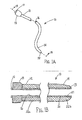
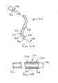
- FIGS. 1A and 1B show an exemplary apparatus 10 for accessing a body lumen (not shown) and/or for delivering one or more fluids, agents, and/or instruments (also not shown) within a body lumen.
- the apparatus 10 may be a guide catheter, a procedure catheter, a sheath, an imaging device, or other tubular device sized for introduction into a body lumen, such as a vessel within a patient's vasculature, a passage within a patient's gastrointestinal tract, urogenital tract, reproductive tract, respiratory tract, lymphatic system, and the like, as described further below.
- the apparatus 10 is an elongate tabular member including a proximal end 12, a distal end 14 sized for insertion into a body lumen, and a lumen 16 extending between the proximal and distal ends 12, 14.
- the apparatus 10 may include one or more additional lumens (not shown), which may be disposed concentrically around or side-by side with the lumen 16.
- the lumen 16 may be sized for receiving a guide wire, procedure catheter, cardiac lead, needle, or other instrument (not shown), and/or for delivering fluids or other flowable agents or materials therethrough.
- the distal end 14 may include a tapered, rounded, or otherwise shaped distal tip 15, e.g., to provide a substantially atraumatic tip and/or facilitate advancement or navigation through various anatomy.
- the distal end 14 may include one or more therapeutic and/or diagnostic elements, e.g., one or more balloons, stents, sensors, electrodes, steering mechanisms, imaging devices, needles, and the like (not shown), depending upon the particular intended application for the apparatus 10.
- the proximal end 12 may include a handle 13 and/or one or more ports, e.g., port 17 communicating with the lumen 16.
- the handle 13 and/or proximal end 12 may include one or more connectors, such as luer lock connectors, electrical connectors, and the like, for connecting other devices (not shown) to the apparatus 10, such as syringes, displays, controllers, and the like (also not shown).
- the handle 13 may include one or more actuators, such as sliders, buttons, switches, and the like, e.g., for activating and/or manipulating components (also not shown) on the distal end 14 or otherwise operating the apparatus 10.
- the apparatus 10 generally includes an inner liner 20 surrounding the lumen 16 and an outer layer 22 surrounding the inner liner 20.
- the inner liner 20 may include a relatively thin film, sheet, or other material including an inner surface 21.
- the inner surface 21 may include a coating having one or more desired properties, e.g., a predetermined lubricity, hydrophilic characteristic, and the like.
- the outer layer 22 may be attached to the inner layer 20, e.g., by laminating, adhering, adhesive bonding, ultrasonic welding, reflowing or other heating, and the like, as described elsewhere herein.
- the outer layer 22 may include one or more sublayers (not shown).
- the outer layer 22 may include a braided or helical reinforcing layer (not shown) surrounding the inner layer 20 and one or more tubular layers (also not shown) surrounding the reinforcing layer and/or between the reinforcing layer and the inner layer 20.
- the reinforcing layer may include one or more round or flat wires, filaments, strands, and the like, e.g., formed from metal, such as stainless steel, plastic, woven fibers, such as glass, Kevlar, and the like, or composite materials.
- Materials that may be used in the outer layer 22 include PEBAX, urethane, FEP, PFA, polyethylene ("PE"), polyamide (Nylon), silicone, polypropylene, polysulfone, polyvinylchloride (PVC), polystyrene, polycarbonate, polymethylmethacrylate, and the like. Materials may be primarily selected for optimal mechanical, bonding, and/or other properties and subsequently imparted with desired surface properties, for example lubricity, by coating.
- Exemplary outer layers that may be included in the apparatus 10 and methods for making them are disclosed in U.S. Patent Nos. 4,478,898 , 4,863,442 , 5,217,440 , 5,254,107 , 5,676,659 , 5,811,043 , 5,836,926 , 6,004,310 , 6,669,886 , 6,837,890 , and 6,945,970 .
- the outer layer 22 may have a substantially homogenous construction between the proximal and distal ends 12,14. Alternatively, the construction may vary along the length of the apparatus 10 to provide desired properties.
- the outer layer 22a af or adjacent the proximal end 12 may be substantially rigid or semi-rigid, e.g., providing sufficient column strength to allow the apparatus 10 to be pushed from the proximal end 12.
- the reinforcing layer or other material in the outer layer 22 may allow the apparatus 10 to be twisted from the proximal end 12, e.g., to rotate the distal end 14 within a patient's body.
- the distal end 14 of the apparatus 10 may be manipulated within a patient's body from the proximal end 12 without substantial risk of buckling and/or kinking
- the outer layer 22b at or adjacent the distal end 14 may be substantially flexible or semi-rigid, e.g., to allow the distal end 14 to bend easily or otherwise be advanced through tortuous anatomy and/or provide a substantially atraumatic distal tip 15.
- the outer layer 22a may have one or more transition regions along its length, transitioning from one desired construction to another.
- the apparatus 10 may have an outer diameter between about half and twenty millimeters (0.5-20 mm), and a length between about five and one hundred fifty centimeters (5-150 cm).
- the inner liner 20 may have a wall thickness between about 0.0025-0.25 mm (0.0001-0.01 inch) and the outer layer 22 may have a wall thickness between about 0.0127-5.08 mm (0.0005-0.2 inch).
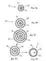
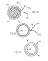
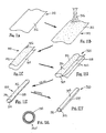
- a first exemplary method is shown for making a tubular device, such as apparatus 10 described above.
- a thin film sheet 30 may be provided including a first side edge 32 and a second side edge 34 opposite one another, and a first upper surface 36 and a second lower surface (not shown).
- the sheet 30 may be formed from a single layer or multiple layers of material.
- the sheet 30 may be formed from a sheet of polyurethane, e.g., having a thickness between about 0.0025-0.25 mm (0.0001-0.01 inch).
- the polyurethane may be Ether-based or Ester-based.
- other suitable polymers may also be used, such as PEBAX and nylon.
- the sheet 30 With the sheet 30 substantially flat, a coating 38 is applied to the first surface 36.
- the sheet 30 may be disposed in a concave, convex, or other nonplanar configuration (not shown), as long as the first surface 36 is readily accessible.
- the coating includes a hydrophilic material, such as Polyvinylpyrrolidone, and is sprayed onto the first surface 36 to apply a substantially uniform thickness coating.
- a hydrophilic material such as Polyvinylpyrrolidone
- the coating may be applied using other procedures, such as rolling, brushing, spreading by maer rods, or dipping, e.g., to provide a substantially uniform thickness coating 38 on the first surface 36.
- the hydrophilic material may provide a predetermined lubricity on the first surface 36.
- the sheet 30 may be rolled such that the first and second side edges 32, 34 are disposed adjacent one another and the first upper surface 36 is now disposed inwardly.
- the first and second side edges 32, 34 may then be attached to one another to create a relatively thin-walled sleeve 40.
- the side edges 32, 34 may be lapped against one another along the uncoated surface or the side edges 32, 34 may be butted against one another.
- the slide edges 32, 34 may then be attached to one another to create a longitudinal seam 35, as shown in FIG. 2D .
- the sheet 30 may be wrapped around a mandrel (not shown), which may facilitate attaching the side edges 32, 34 and/or facilitate maintaining a desired inner diameter for the sleeve 40.
- the coating 38 may not interfere with attaching the side edges 32, 34 together, because the contact surface between the side edges 32, 34 is uncoated.
- the side edges 32, 34 are attached to one another by heat bonding, i.e., heating to fuse the side edges 32, 34 together, using ultrasonic energy, and/or using one or more adhesives.
- the resulting device is a relatively thin-walled sleeve 40 including a lumen 39 having an inner surface coated, as shown in FIG. 2D .
- the excess material may be cut away or otherwise removed from the thin-walled sleeve 40.
- the thin-walled sleeve 40 may be incorporated into a catheter or other tubular device, similar to the apparatus 10 described above. It will be noted that annular spaces are shown between the various layers or components shown in the drawings. These spaces are not to scale but are shown merely to clarify the various components. It will be appreciated that the spaces may be relatively small or adjacent components may directly contact one another such that there is little or substantially no space between the contacting components or layers.
- the thin-walled sleeve 40 may be positioned around a mandrel 50, thus creating a first assembly 42.
- the mandrel 50 may be an elongate cylindrical structure, e.g., a tube or rod, formed from material able to withstand the parameters used during assembly, e.g., elevated temperatures used to heat the materials during assembly.
- the thin-walled sleeve 40 may fit relatively snugly around the mandrel 50 such that the inner surface 36 is substantially smooth, e.g., without substantial wrinkles or other irregularities.
- the mandrel 50 may be formed from or coated with a lubricious, hydrophilic, or other material that is non-bondable to the thin-walled sleeve 40.
- Exemplary materials for the mandrel 50 may include metal, such as stainless steel, coated stainless steel, NiTi alloy, MP35N, Elgiloy, and the like.
- plastic such as Teflon, composite, or non-metallic materials may be used.
- a tubular structure 48 is then positioned over the first assembly 42, creating a second assembly 46.
- the tubular structure 48 may be an extrusion-of PEBAX, nylon, polylmide, HDPE, Plexar, and/or Urethane having an inner diameter sized to slide around the thin-walled sleeve 40.
- other suitable materials described herein may also be employed, such as the multiple sublayer outer layers described above.
- the tubular structure 48 may have a thickness that is substantially greater than a thickness of the thin-walled sleeve 40.
- the tubular structure 48 may provide the desired structural integrity of the final apparatus being constructed.
- the material of the thin-walled sleeve may also be selected based on desired mechanical or structural properties and desired surface properties subsequently imparted by coating.
- the tubular structure 48 may be extruded or otherwise flowed around the thin-walled sleeve 40, or may be preformed and then threaded or otherwise advanced over the thin-walled sleeve 40.
- the tubular structure 48 may be built up around the thin-walled sleeve 40, e.g., by applying one or more successive layers around the thin-walled sleeve 40 until a desired outer layer is obtained.
- heat shrink tubing 45 may be positioned over the second assembly 46, and then heat may be applied to the heat shrink tubing 45, e.g., sufficient to cause the shrink tubing 45 to shrink around the second assembly 46.
- the combination of heat and inward compression may cause the tubular structure 48 to at least partially melt or otherwise reflow around the thin-walled sleeve 40, thereby fusing the tubular structure 48 to the thin-walled sleeve 40.
- hot air may be blown around the shrink tubing 45 or the entire assembly may be placed in an oven, creating sufficient heat to cause the shrink tubing 45 to constrict around the tubular structure 48.
- the shrink tubing 45 may then be removed from the second assembly 46.
- the shrink tubing 45 may be formed from a material that may be torn easily.
- the shrink tubing 45 may include one or more weakened seams, tabs, and the like (not shown) to facilitate removing the shrink tubing from around the second assembly 46.
- the shrink tubing 45 may be rolled, slid, or otherwise removed from one end of the tubular structure 48.
- the mandrel 50 may be removed from within the thin-walled sleeve 40 either before or after removing the shrink tubing 45.
- tubular device that includes an outer layer 48, and a lumem 44 including a coated inner surface.
- additional components may be added to the tubular device, such as a handle and/or one or more therapeutic and/or diagnostic elements, as described above.
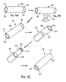
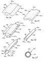
- FIGS. 4A-4G another method is shown for making a tubular device, such as apparatus 10 described above.
- a relatively thin-walled sleeve 58 may be provided that initially includes first and second ends 57, 59 defining an outer surface 54 and an inner surface 53 extending therebetween.
- the thin-walled sleeve 58 may include a tube of thin-walled material including one or more layers, similar to the sheet described above.
- the thin-walled sleeve 58 may be formed from a sheet that is rolled and has its longitudinal edges sealed or otherwise bonded (similar to the method described above, but without coating).
- the thin-walled sleeve 58 is coated on the outer surface 54.
- a desired liquid material 55 may be sprayed or brushed onto the outer surface 54, e.g., to provide a substantially uniform thickness hydrophilic coating on the outer surface 54.
- the coating may be applied by dipping the thin-walled sleeve 48 in a desired solution, e.g., a hydrophilic composition.
- plasma deposition, electrostatic deposition, vapor deposition, and the like may be used.
- the thin-walled sleeve may be positioned over a mandrel (not shown), pressurized, or otherwise supported to facilitate application of a desired liquid, solution, and/or coating.
- the coated thin-walled sleeve 58 is then inverted so that the coated outer surface 54 and the inner surface 53 are now arranged on the interior and exterior of thin film sleeve 58, respectively.
- the first end 57 of the thin-walled sleeve 58 may be pulled inwardly through the thin-walled sleeve 58 and out the second end 59.
- the coated surface now occupies the interior of the thin-walled sleeve 58.
- a tubular structure 52 may then be attached to or around the inverted thin-walled sleeve 58 to provide a tubular device 56. Similar to the previous embodiments, the inverted thin-walled sleeve 58 may be positioned over a mandrel 50. The tubular structure 52 may then be positioned over the inverted thin-walled sleeve 58, thereby capturing the thin-walled sleeve 58 within the lumen 52a.
- the tubular structure 52 may be a slotted tube defining a lumen 52a, and including longitudinal edges 51 a, 51b defining a slot therebetwem that communicates with the lumen 52a.
- the tubular structure 52 may be formed from one or more layers, as described elsewhere herein.
- the tubular structure 52 may be formed as a generally "C" shaped cross-section, e.g., by extrusion, injection molding, lay-up, and the like.
- the tubular structure 52 may be formed as a continuous-walled tube, which may be slit or otherwise cut to create the slot and the longitudinal edges 51a,.51b.
- the longitudinal edges 51a, 51b may be separated away from one another sufficient distance to allow the mandrel 50 and thin-walled sleeve 58 thereon to pass between the longitudinal edges 51a, 51b and enter the lumen 52a.
- the diameter of the lumen 52a may be slightly smaller than the outer diameter of the thin-walled sleeve 58 on the mandrel 50. This embodiment may ensure that the tubular structure 52 is fitted snugly around the thin-walled sleeve 58.
- tubular structure 52 and the inverted thin-walled sleeve 58 may then be bonded or otherwise attached to one another.
- heat shrink tubing (not shown) may be positioned around the tubular structure 52 and heated to cause the shrink tubing to heat and/or compress radially inwardly the tubular structure 52.
- the entire assembly may be directed through a heated die.
- tubular structure 52 may at least partially melt or reflow, thereby fusing or otherwise bonding the longitudinal edges 51a, 51b together to provide a continuous wall.
- heating may reflow, fuse, or otherwise bond the inverted thin-walled sleeve 58 to the inner surface of the tubular structure 52.
- other processes may be used, such as delivering ultrasonic energy, lamination, and/or applying adhesives to attach the tubular structure 52 around the inverted thin-walled sleeve 58.
- the resulting tubular device 56 (having lubricious inner surface 56a) is removed from the mandrel 50.
- other components (not shown) may be added to the tubular device 56, as described elsewhere herein.
- FIG. 4E another method is shown for attaching a tubular structure 52 over the inverted thin walled sleeve 58.
- a reinforcement layer 52b may be applied around the inverted thin-walled sleeve 58.
- one or more wires, filaments, or other strands may be wound or otherwise positioned around the inverted thin-walled sleeve 58, e.g., in a braided pattern (shown in FIG. 4E ) or in a helical pattern (not shown).
- a tubular structure 52 may then be applied around the reinforcement layer 52b.
- the tubular structure 52 may include one or more layers applied successively around the reinforcing layer 52b.
- filament wound fibers and polymeric material may be wound around the reinforcing layer 52b or thermoplastic or other flowable material may be extruded or otherwise directed around the reinforcing layer 52b.
- FIG. 4F an alternative method is shown for attaching the tubular structure 52 around the inverted thin-walled sleeve 58.
- the tubular structure 52 is a completely formed tube that may be positioned over and bonded to the inverted thin-walled sleeve 58.
- an adhesive may be applied around the inverted thin-walled sleeve 58, and the tubular structure 52 may be advanced over the adhesive.
- the adhesive may then be cured, e.g., by heating, pressure, ultraviolet light exposure, and/or allowing sufficient time to cure.
- the mandrel 50 may then be removed, e.g., to provide the tubular device 56 shown in FIG. 4G .
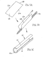
- a thin-walled sheet 68 may be provided that includes a first upper surface 64, a second lower surface (not shown), and opposing longitudinal edges 69a, 69b.
- the thin-walled sheet 68 may comprise materials and configurations, similar to other methods described elsewhere herein.
- the first surface 64 of the thin-walled sheet 68 is coated, as described elsewhere herein, to provide a desired coating having one or more desired properties on the first surface 64 .
- the one or more desired properties may include a predetermined lubricity on the first surface 64, e.g., provided by a hydrophilic coating, such as those described elsewhere herein.
- the thin-walled sheet 68 is partially wrapped around a mandrel 50 such that the first surface 64 is disposed inwardly towards the mandrel 50.
- a slotted tube 62 may be provided that may be formed similar to the methods described elsewhere herein.
- the slotted tube 62 may include opposing longitudinal edges 61, 63 defining a slot communicating with a lumen 65 of the slotted tube 62.
- the slotted tube 62 may be positioned around the thin-walled sheet 68 by separating the longitudinal edges 61, 63 sufficiently to insert the mandrel 50 and thin-walled sheet 68 through the slot and into the lumen 65. As shown, the longitudinal edges 69a, 69b of the thin-walled sheet 68 may extend out from between the longitudinal edges 61, 63 of the slotted tube 62.
- the slotted tube 62 may then be attached to the thin-walled sheet 68, e.g., by heat-sealing, advancement through a heated die or other lamination, bonding, and the like, as described elsewhere herein.
- heating of the assembly may cause the material of the slotted tube 62 to at least partially reflow, thereby fusing or otherwise bonding the longitudinal edges 61, 63 together.
- the assembly may be heated to attach the thin-walled sheet 68 to the inner surface of the slotted tube 62 and within the slot
- Excess material from the longitudinal edges 69a, 69b of the thin-walled sheet 68 may remain exposed outside the (no longer slotted) tube 62. This excess material may be cut or otherwise trimmed along the wall of the tube 62, resulting in the tubular device 66 shown in FIG. 5F .
- the mandrel 50 is removed from the bonded thin film sheet 68 and slotted tube 62, either before or after trimming the excess longitudinal edges 69a, 69b.
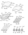
- a relatively thick sheet 78 may be provided that includes a first upper surface 74, a second lower surface 75, first and second side edges 77a, 77b, and a thickness 79.
- the sheet 78 may be formed from one or more layers of material, similar to the tubular structures described elsewhere herein, except provided in a relatively flat configuration (or a concave, convex, or other nonplanar configuration where the first surface 74 is readily accessible, similar to other methods herein).
- the thickness 79 of the sheet 78 may be between about 0.0127-5.08 mm (0.0005-0. 2 inch).
- the first surface 74 of sheet 78 is coated, e.g., similar to the methods describe elsewhere herein, to provide a substantially uniform thickness coating 88 on the first surface.
- the coating 88 may include a hydrophilic material that provides a desired lubricity to the first surface 74.
- the coated sheet 78 may be positioned near and rolled around a mandrel 50 with the coated first surface 74 disposed inwardly.
- the first side edge 77a may be disposed adjacent the second side edge 77b, thereby providing a tubular structure defining a lumen.
- the first and second side edges 77a, 77b may then be bonded or otherwise attached to one another, e.g., using heat bonding, lamination, ultrasonic energy, or adhesives, as described elsewhere herein.
- the tubular device 76 may be removed from the mandrel 50, thereby resulting in the tubular device 76 having the lubricious inner surface 74.
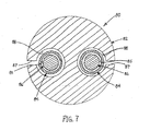
- FIG. 7 another tubular assembly 80 is shown that includes an outer tubular body 82, a pair of thin-walled sleeves 84, and a pair of mandrels 86.
- the thin-walled sleeves 84 may be formed from flat sheets or tubular sleeves that have a coating on an inner surface 85 thereof.
- the coating may be applied before the sheet is rolled and formed into the sleeves 84 or while the sleeves 84 are in a tubular form (e.g., by coating an outer surface and inverting the sleeves 84).
- the sleeves 84 may be positioned around respective mandrels 86.
- the outer tubular body 82 includes a pair of lumens 88 extending longitudinally through the tubular body 82.
- the tubular body 82 may be an extrusion or other single or multiple layer tubular structure, similar to other methods described herein.
- the tubular body 82 may be formed as a continuous walled tube, which may be slit along its length to provide slots 87 communicating with respective lumens 88.
- the tubular body 82 may be positioned around the mandrels 86 and thin-walled sleeves 84, similar to the previous methods.
- each slot 87 may be opened sufficiently to insert a mandrel 86 carrying a thin-walled sleeve 84 through the slot 87 into the lumen 88.
- the mandrels 86 may be inserted longitudinally into the respective lumens 88 with the thin-walled sleeves 84 thereon. In this alternative, it may be possible to eliminate the slots 87.
- the tubular body 82 may be attached to the thin-walled sleeves 84, e.g., by heating as described above, thereby reflowing the material of the tubular body 82 to close the slots 87 and provide a continuous wall structure.
- the mandrels 86 may then be removed, thereby providing a tabular device having lumens 88 having coated inner.surfaces.
- tubular devices may be created that include multiple lumens, each of which may include a desired coating along its inner surface.
- a sheath apparatus 108 that includes a tubular proximal portion 110 and an expandable distal portion 118.
- the proximal portion 110 may include at least one lumen 116 including a coated liner (not shown), such as any of the methods described herein.
- the proximal portion 110 is an elongate tubular member, e.g., a catheter, sheath, and the like, including a proximal end 112, a distal end 114 sized for insertion into a body lumen, and a lumen 116 extending between the proximal and distal ends 112, 114.
- the tubular proximal portion 110 may include one or more additional lumens (not shown), e.g., for receiving a guide wire, inflation media, and/or for perfusion. Such additional lumens may be disposed concentrically around one another or in a side-by-side arrangement.
- the expandable distal portion 118 may include an elongate stiffening member 120 providing a "backbone" for the distal portion 118 and an expandable sheath 130. Additional information on materials and methods for making the apparatus 108 are disclosed in co-pending applications US 2003-0233115, filed April 24, 2003 , US 2005-0085842, filed September 2, 2004 , US 2005-0085841, filed September 2, 2004 , and US 2005-0149104, filed October 4, 2004 .
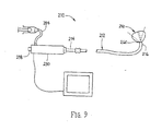
- an apparatus 210 for imaging a body lumen, e.g., for visualizing, accessing, and/or cannulating a body lumen from a body cavity (not shown).
- the apparatus 210 includes a catheter or other elongate member 212, including a handle 230 on a proximal end 214 of the catheter 212, and a balloon or other expandable member 250 on a distal end 216 of the catheter 212.
- An imaging assembly 260 may be provided on or otherwise carried by the catheter 212 for imaging through the balloon 250, e.g. including one or more illumination fibers and/or imaging optical fibers (not shown) extending through the catheter 212.
- the catheter 212 may include one or more lumens (not shown) extending between the proximal and distal ends 214, 216 that may include a coated liner or inner surface, as described elsewhere herein.
- an accessory lumen may extend from a port 238 in the handle 230 through the balloon 250.
- the lumen may be coated or otherwise lined to facilitate introducing one or more instruments (not shown) the through the apparatus 210.
- a delivery sheath 10 may be provided that includes an inner polyurethane liner 20 having a coating on its inner surface 21.
- the liner 20 may have a thickness between about 0.0127-0.25 mm (0.0001-0.01 inch), or between about 0.0025-0.076mm (0.0001-0.003 inch).
- the coating may include a lubricious and/or hydrophilic material applied using any of the methods described herein.
- the inner liner 20 may be formed from a coated sheet or an inverted tube, as described elsewhere herein.
- the sheath 10 may include an outer layer 22 that includes a stainless steel braid (not shown) surrounding the inner liner 20 and a layer of PEBAX or urethane surrounding the braid.
- the layer of PEBAX or urethane may have a thickness between about 0.1-0.5 mm (0.004-0.02 inch).
- the sheath 10 may define a lumen 16 having a diameter between about one and five millimeters (1-5 mm), depending upon the particular application for the sheath 10.
- the device 10 may be a core for passage of a guidewire (not shown).
- the inner liner 20 may include a layer of polyurethane having a thickness between about 0.0025-0.038 mm (0.0001-0.0015 inch) thickness.
- An inner surface 21 of the liner 20 may be coated as described elsewhere herein, e.g., with a lubricious and/or hydrophilic materials.
- the outer layer 22 may include a tubular body formed from nylon, PEBAX, or urethane having a thickness between about 0.0127-0.076 mm (0.0005-0.006 inch).
- the resulting device 10 may include a lumen 16 having a diameter between about 0.40-1.15 mm (0.016-0.045 inch).
- the device 10 may be provided within a catheter, guidewire, or other tubular device (not shown), which may be constructed in any known manner.
- the device 10 may be bonded or otherwise attached within a lumen of the tubular device, similar to the methods described above, to provide a lubricious or otherwise coated inner lumen 16.
- an elongate lead 310 that includes a proximal end 312, a distal end 314 sized and/or shaped for introduction into a patient's vasculature, and one or more electrodes 316 (one shown) on the distal end 314.
- the lead 310 is formed from a lead body, which may be formed, for example, from silicone, polyurethane, or other materials defining an outer surface 318.
- the lead body may have a uniform construction along its length or may vary, similar to other arrangements described herein.
- the lead 310 may include other components, e.g., one or more wires or other conductors (not shown) extending between the electrode(s) and the proximal end 312, one or more mechanical and/electrical connectors (also not shown) on the proximal end 312, and the like.
- the lead 310 includes an outer cover 320 surrounding at least a portion of the outer surface 318.
- the cover 320 may include a layer of polyurethane, e.g., having a thickness between about 0.0127-0.076 mm (0.00025-0.003 inch).
- the cover 320 includes a coating on its outer surface 322, which may be any of the coatings described herein, e.g., including a lubricious and/or hydrophilic material.
- the-cover 320 extends along the distal end 314 of the lead 310, e.g., immediately adjacent the electrode 316.
- the cover 320 may extend over the electrode 316 (not shown).
- the cover 320 may extend proximally from the distal end 314 towards the proximal end 312 (also not shown).
- a plurality of covers may be provided spaced apart from one another along the length of the lead 310. The covers may include similar or different coatings from one another, depending upom the properties desired for different portions of the lead 310.
- the cover 320 may include a weakened seam 324 extending along a length of the cover 320.
- the seam 324 may be a thin-walled region, a perforated seam, and the like.
- a plurality of weakened seams may be provided.
- the seam 324 may facilitate removal of the cover 320, if desired.
- a thread, tab, or other element may extend from the cover 320, e.g., to the proximal end 312 of the lead 310. Such an element may be grasped or otherwise manipulated to remove the cover 320, e.g., pulled to cause the seam 324 to tear and peel the cover 320 from around the lead 310.
- the cover 320 may be made similar to the liners described above, e.g., as a sheet or tube (but without being inverted). The cover 320 may be simply slid over the lead 310, heat shrunk around the lead 310, or bonded onto the outer surface 318 (depending upon whether the cover 320 is removable).
- the lead 310 may be introduced using conventional methods.
- the cover 320 may facilitate advancing the distal end 314 through tortuous anatomy, e.g., if the cover 320 includes a lubricious coating.
- the cover 320 may be removed from over the distal end 314.
- a tab adjacent the proximal end 312 and coupled to the cover 320 may be pulled to tear or otherwise remove the cover 320.
- Removing the cover 320 may facilitate maintaining the distal end 314 at the desired location, i.e., minimizing migration that may occur of the cover remains over the distal end 314.
- the underlying outer surface 318 of the lead 310 may include materials, features, coatings, and the like that enhance securing the distal end 314 once the cover 320 is removed.
- a thin film sheet 310 may be provided including a first upper surface 312 and a second lower surface 314 (not shown in FIG. 11A , see, e.g., FIG. 11C ).
- the sheet 310 may be formed from a single layer or multiple layers of material, similar to the other methods described elsewhere herein.
- the sheet 310 may be formed from a sheet of polyurethane, e.g., having a thickness between about 0.0025-0.076 mm (0.0001-0.003 inch). However, other suitable polymers may also be used.
- a coating 316 is applied to the first surface 312.
- a pre-formed thin membrane sleeve may be coated on its outer surface and subsequently inverted, as described elsewhere herein.
- the coating may include a hydrophilic material, such as Polyvinylpyrrolidone, sprayed onto the first surface 312.
- a hydrophilic material such as Polyvinylpyrrolidone
- the coating may be applied using other procedures, such as rolling, brushing, spreading by maer rods, or dipping, e.g. on the first surface 312.
- the hydrophilic material may provide a predetermined lubricity on the first surface 312.
- other materials may be applied to provide one or more desired properties on the first surface 312, e.g. anti-thrombotic or anti-hemolytic materials, drug-eluting coatings, and the like.
- these materials may also be applied to the second surface (not shown).
- other materials for example, adhesives, primers, reinforcing element, backing material, and the like, may be applied to the second surface 314, e.g., to facilitate construction or processing of a thin-walled sleeve or a subsequent apparatus, as described elsewhere herein.
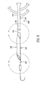
- the sheet 310 may be folded over such that the first surface 312 is disposed outwardly and the second surface 314 is disposed inwardly.
- a longitudinal seam 318 may then be created to create a relatively thin walled sleeve 320.
- the longitudinal seam may be created by heat bonding, using ultrasonic energy, using one or more adhesives, and/or as otherwise described elsewhere herein.
- excess material 322 may be trimmed from the thin-walled sleeve 320.
- the thin-walled sleeve 320 may then be inverted, as described elsewhere herein, such that the first surface 312 is now disposed inwardly.
- a thin-walled sleeve may be created by disposing the coated first surface 312' of the thin film sheet 310 inwardly before creating a longitudinal seam (not shown).
- this method there is no need to invert the thin-walled sleeve 320' in order to dispose the coated first surface 312' inwardly.
- one or more outer layers may be bonded or otherwise provided around the thin-walled sleeve 320 or 320,' similar to the other methods described elsewhere herein.
- FIGS. 12A-12F another method is shown for making a coated thin-walled sleeve.
- two thin film sheets 410a, 410b may be provided, similar to the other methods - described herein.
- Each sheet 410a, 41b includes a first upper surface 412a, 412b and a second lower surface 414a, 414b (not shown in FIG. 12A ).
- a coating 416 may be applied, as described elsewhere herein, to each first surface 412.
- each second surface 414 may also be coated as described elsewhere herein.
- the second surfaces 414 of sheets 410 may be placed adjacent to one another and at least two longitudinal seams 418 may then be created to form a relatively thin-walled sleeve 420. Excess material 422 may be trimmed from the thin-walled sleeve 420, as shown in FIG. 12D .
- the thin-walled sleeve 420 may then be inverted such that the first surfaces 412 are now disposed inwardly.
- a thin-walled sleeve 320' may be created by disposing the coated first surfaces 412 of the thin film sheets 410 inwardly before creating the longitudinal seams (not shown). Using this method, there is no need to invert the thin-walled sleeve 420' in order to dispose the coated first surfaces 412 inwardly.
- other methods may be used, such as those described elsewhere herein, which may include orienting a coated surface such that inversion is not required subsequent to seam creation in order to dispose the coated surface inwardly.
- FIGS. 13A-13F another method is shown for making coated thin-walled sleeves.
- two thin film sheets 510a, 510b may be provided similar to other methods wherein, each including a first upper surface 512a, 512b and a second lower surface 514a, 514b (not shown in FIG. 13A ).
- a coating 516 is applied to each first surface 512, as described elsewhere herein.
- each second surface 514 may also be coated, as described elsewhere herein.
- the second surfaces 514 of sheets 510 may be placed adjacent to one another and a plurality of (e.g., at least three) longitudinal seams 518 may then be created to form at least two relatively thin-walled sleeves 520.
- the sleeves 520 maybe separated and excess material 522 may be trimmed from the thin-walled sleeves 520, as shown in FIG. 13D .
- a longitudinal cut may be created at the same time each longitudinal seem 518 is created or subsequent to creating each longitudinal seam 518, thereby, separating adjacent thin-walled sleeves 520 from one another.
- each thin-walled sleeve 520 may be inverted such that the coated first surfaces 512 are now disposed inwardly.
- multiple thin-walled sleeves 520' may be created by disposing the coated first surfaces 516' of the thin film sheets inwardly creating longitudinal seams (not shown). Using this method, there is no need to invert the thin-walled sleeves 520' in order to dispose the coated first surfaces inwardly.
Landscapes
- Health & Medical Sciences (AREA)
- Life Sciences & Earth Sciences (AREA)
- Engineering & Computer Science (AREA)
- Veterinary Medicine (AREA)
- Public Health (AREA)
- General Health & Medical Sciences (AREA)
- Animal Behavior & Ethology (AREA)
- Heart & Thoracic Surgery (AREA)
- Biomedical Technology (AREA)
- Mechanical Engineering (AREA)
- Biophysics (AREA)
- Pulmonology (AREA)
- Anesthesiology (AREA)
- Hematology (AREA)
- Epidemiology (AREA)
- Radiology & Medical Imaging (AREA)
- Nuclear Medicine, Radiotherapy & Molecular Imaging (AREA)
- Cardiology (AREA)
- Vascular Medicine (AREA)
- Materials For Medical Uses (AREA)
- Media Introduction/Drainage Providing Device (AREA)
Applications Claiming Priority (3)
| Application Number | Priority Date | Filing Date | Title |
|---|---|---|---|
| US72330005P | 2005-10-04 | 2005-10-04 | |
| US11/340,904 US7553387B2 (en) | 2005-10-04 | 2006-01-26 | Catheters with lubricious linings and methods for making and using them |
| PCT/US2006/039074 WO2007041695A2 (en) | 2005-10-04 | 2006-10-04 | Catheters with lubricious linings and methods for them |
Publications (2)
| Publication Number | Publication Date |
|---|---|
| EP1931411A2 EP1931411A2 (en) | 2008-06-18 |
| EP1931411B1 true EP1931411B1 (en) | 2013-04-10 |
Family
ID=37671917
Family Applications (1)
| Application Number | Title | Priority Date | Filing Date |
|---|---|---|---|
| EP06825533.0A Active EP1931411B1 (en) | 2005-10-04 | 2006-10-04 | Methods for making catheters with lubricious linings |
Country Status (5)
| Country | Link |
|---|---|
| US (1) | US7553387B2 (enExample) |
| EP (1) | EP1931411B1 (enExample) |
| JP (1) | JP2009509718A (enExample) |
| CA (1) | CA2624287C (enExample) |
| WO (1) | WO2007041695A2 (enExample) |
Cited By (2)
| Publication number | Priority date | Publication date | Assignee | Title |
|---|---|---|---|---|
| KR20180103853A (ko) * | 2016-02-05 | 2018-09-19 | 보드 오브 리전츠 오브 더 유니버시티 오브 텍사스 시스템 | 조종가능한 루멘 내 의료 기기 |
| EP4461201A3 (en) * | 2017-07-31 | 2025-01-29 | XCATH, Inc. | Steerable medical device and the preparing method thereof |
Families Citing this family (50)
| Publication number | Priority date | Publication date | Assignee | Title |
|---|---|---|---|---|
| US7550053B2 (en) * | 2006-01-26 | 2009-06-23 | Ilh, Llc | Catheters with lubricious linings and methods for making and using them |
| US9974887B2 (en) | 2005-10-04 | 2018-05-22 | Clph, Llc | Catheters with lubricious linings and methods for making and using them |
| US8070898B2 (en) * | 2005-10-04 | 2011-12-06 | Clph, Llc | Catheters with lubricious linings and methods for making and using them |
| US11433216B2 (en) * | 2018-09-17 | 2022-09-06 | Seigla Medical, Inc. | Methods for fabricating medical devices and portions of medical devices |
| US11547835B2 (en) * | 2018-09-17 | 2023-01-10 | Seigla Medical, Inc. | Systems, methods and apparatus for guiding and supporting catheters and methods of manufacture |
| US11660420B2 (en) | 2018-09-17 | 2023-05-30 | Seigla Medical, Inc. | Catheters and related devices and methods of manufacture |
| EP2190388B1 (en) * | 2007-10-17 | 2014-03-05 | Angiomed GmbH & Co. Medizintechnik KG | Delivery system for a self-expanding device for placement in a bodily lumen |
| US8673100B2 (en) * | 2007-10-19 | 2014-03-18 | Stephen A. Leeflang | Strip lined catheters and methods for constructing and processing strip lined catheters |
| GB0815339D0 (en) * | 2008-08-21 | 2008-10-01 | Angiomed Ag | Method of loading a stent into a sheath |
| CN102014806B (zh) * | 2008-05-09 | 2013-10-30 | 安吉奥米德医药技术有限责任两合公司 | 将扩张件置入套管中的方法 |
| US8403896B2 (en) * | 2008-08-29 | 2013-03-26 | AUST Development, LLC | Apparatus and methods for making coated liners and tubular devices including such liners |
| US8690936B2 (en) * | 2008-10-10 | 2014-04-08 | Edwards Lifesciences Corporation | Expandable sheath for introducing an endovascular delivery device into a body |
| US8790387B2 (en) | 2008-10-10 | 2014-07-29 | Edwards Lifesciences Corporation | Expandable sheath for introducing an endovascular delivery device into a body |
| WO2010048186A2 (en) * | 2008-10-20 | 2010-04-29 | Dunstone Company Inc. | Heat-shrinkable sleeve for use on tooling during the process of manufacturing composite parts |
| US9351871B2 (en) * | 2008-11-12 | 2016-05-31 | Alcon Research, Ltd. | Distal plastic end infusion/aspiration tip |
| JP5753495B2 (ja) * | 2008-11-24 | 2015-07-22 | クック・メディカル・テクノロジーズ・リミテッド・ライアビリティ・カンパニーCook Medical Technologies Llc | 補強されたチューブを形成する方法 |
| GB0823716D0 (en) | 2008-12-31 | 2009-02-04 | Angiomed Ag | Stent delivery device with rolling stent retaining sheath |
| US8454578B2 (en) * | 2009-02-18 | 2013-06-04 | AUST Development, LLC | Apparatus and methods for making coated liners and tubular devices including such liners |
| GB0921238D0 (en) * | 2009-12-03 | 2010-01-20 | Angiomed Ag | Stent device delivery system and method of making such |
| GB0921236D0 (en) * | 2009-12-03 | 2010-01-20 | Angiomed Ag | Stent device delivery system and method of making such |
| GB0921240D0 (en) | 2009-12-03 | 2010-01-20 | Angiomed Ag | Stent device delivery system and method of making such |
| GB0921237D0 (en) * | 2009-12-03 | 2010-01-20 | Angiomed Ag | Stent device delivery system and method of making such |
| US9986893B2 (en) | 2009-12-15 | 2018-06-05 | Cornell University | Method and apparatus for manipulating the side wall of a body lumen or body cavity so as to provide increased visualization of the same and/or increased access to the same, and/or for stabilizing instruments relative to the same |
| GB201020373D0 (en) | 2010-12-01 | 2011-01-12 | Angiomed Ag | Device to release a self-expanding implant |
| JP6179995B2 (ja) * | 2011-12-05 | 2017-08-16 | ストライカー コーポレイションStryker Corporation | 強化型の伸長医療機器および製造方法 |
| AU2012352062A1 (en) | 2011-12-14 | 2014-07-10 | Semprus Biosciences Corp. | Surface modification for dialysis catheters |
| US9561346B2 (en) | 2012-01-11 | 2017-02-07 | Uc-Care Ltd. | Catheterization apparatus and methods thereof |
| US9539411B2 (en) | 2013-03-13 | 2017-01-10 | W. L. Gore & Associates, Inc. | Deconstructable endoluminal devices and related systems and methods |
| EP3583976B1 (en) | 2013-03-16 | 2023-03-08 | Clph, Llc | Steerable catheters and methods for making them |
| US9629978B2 (en) | 2013-05-20 | 2017-04-25 | Clph, Llc | Catheters with intermediate layers and methods for making them |
| EP3194001B1 (en) | 2014-09-21 | 2019-09-04 | Clph, Llc | Catheter devices and methods for making them |
| EP3215209B1 (en) | 2014-11-05 | 2022-12-21 | Clph, Llc | Catheter devices and methods for making them |
| US10918829B2 (en) | 2015-01-22 | 2021-02-16 | Boston Scientific Scimed, Inc. | Fully compliant large bore expandable sheath |
| US10327896B2 (en) | 2015-04-10 | 2019-06-25 | Edwards Lifesciences Corporation | Expandable sheath with elastomeric cross sectional portions |
| US12194256B2 (en) | 2015-04-10 | 2025-01-14 | Edwards Lifesciences Corporation | Expandable sheath |
| US10792471B2 (en) | 2015-04-10 | 2020-10-06 | Edwards Lifesciences Corporation | Expandable sheath |
| EP4397265A3 (en) | 2015-08-05 | 2024-11-13 | Clph, Llc | Catheter device and methods for making them |
| US10500332B2 (en) | 2015-11-03 | 2019-12-10 | Clph, Llc | Injection devices and systems and methods for using them |
| JP6718265B2 (ja) * | 2016-03-22 | 2020-07-08 | テルモ株式会社 | 医療用チューブの製造方法 |
| US11123519B2 (en) * | 2016-12-21 | 2021-09-21 | Biosense Webster (Israel) Ltd. | Layered tube for improved kink resistance |
| US10912919B2 (en) | 2017-01-23 | 2021-02-09 | Edwards Lifesciences Corporation | Expandable sheath |
| US10799685B2 (en) | 2017-03-09 | 2020-10-13 | Edwards Lifesciences Corporation | Expandable sheath with longitudinally extending reinforcing members |
| US11129959B2 (en) | 2018-02-15 | 2021-09-28 | Boston Scientific Scimed, Inc. | Introducer with expandable capabilities |
| KR102788893B1 (ko) | 2018-04-09 | 2025-04-02 | 에드워즈 라이프사이언시스 코포레이션 | 팽창 가능 외장 |
| US11786695B2 (en) | 2018-07-25 | 2023-10-17 | Edwards Lifesciences Corporation | Methods of making an expandable sheath |
| US12539389B2 (en) | 2018-09-17 | 2026-02-03 | Seigla Medical, Inc. | Catheters and related devices and methods of manufacture |
| EP4232133A4 (en) | 2020-10-23 | 2024-09-11 | Canon U.S.A., Inc. | REINFORCED CENTRAL LIGHT FOR ADJUSTABLE DEVICE |
| EP4243910A4 (en) * | 2020-11-16 | 2024-12-25 | Lumendi Ltd. | METHOD AND DEVICE FOR TURNING A HOLLOW SLEEVE AND SUBSEQUENT REVERSING AN INVERTED HOLLOW SLEEVE |
| GB2606046B (en) * | 2020-12-16 | 2023-08-02 | Ffi Ionix Ip Inc | Extruded thin wall polyether block amide membrane tubing and module |
| US11553830B1 (en) * | 2022-06-14 | 2023-01-17 | Izomed, Inc. | Endoscopic accessory |
Family Cites Families (58)
| Publication number | Priority date | Publication date | Assignee | Title |
|---|---|---|---|---|
| US3879516A (en) * | 1972-12-07 | 1975-04-22 | Technibiotics | Method of constructing a catheter |
| US4516972A (en) * | 1982-01-28 | 1985-05-14 | Advanced Cardiovascular Systems, Inc. | Guiding catheter and method of manufacture |
| US4478898A (en) * | 1982-06-04 | 1984-10-23 | Junkosha Co., Ltd. | Laminated porous polytetrafluoroethylene tube and its process of manufacture |
| US4636346A (en) * | 1984-03-08 | 1987-01-13 | Cordis Corporation | Preparing guiding catheter |
| US4863442A (en) * | 1987-08-14 | 1989-09-05 | C. R. Bard, Inc. | Soft tip catheter |
| US5176661A (en) * | 1988-09-06 | 1993-01-05 | Advanced Cardiovascular Systems, Inc. | Composite vascular catheter |
| US5047045A (en) * | 1989-04-13 | 1991-09-10 | Scimed Life Systems, Inc. | Multi-section coaxial angioplasty catheter |
| US5100381A (en) * | 1989-11-13 | 1992-03-31 | Scimed Life Systems, Inc. | Angioplasty catheter |
| US5217440A (en) * | 1989-10-06 | 1993-06-08 | C. R. Bard, Inc. | Multilaminate coiled film catheter construction |
| EP0530201B1 (en) | 1990-03-15 | 1994-08-03 | W.L. Gore & Associates, Inc. | A catheter liner and a method of making the same |
| US5254107A (en) * | 1991-03-06 | 1993-10-19 | Cordis Corporation | Catheter having extended braid reinforced transitional tip |
| JP2744155B2 (ja) * | 1991-10-28 | 1998-04-28 | 株式会社クリニカル・サプライ | 湿潤時に潤滑性を有する抗血栓性医療用具及びその製造方法 |
| US5447497A (en) * | 1992-08-06 | 1995-09-05 | Scimed Life Systems, Inc | Balloon catheter having nonlinear compliance curve and method of using |
| JPH06190052A (ja) * | 1992-09-18 | 1994-07-12 | Cordis Corp | 繊維強化したカテーテル挿入器 |
| US6090072A (en) * | 1992-10-15 | 2000-07-18 | Scimed Life Systems, Inc. | Expandable introducer sheath |
| WO1995009561A1 (en) * | 1993-10-01 | 1995-04-13 | Target Therapeutics, Inc. | Sheathed multipolar catheter and multipolar guidewire for sensing cardiac electrical activity |
| WO1995013110A1 (en) * | 1993-11-12 | 1995-05-18 | Micro Interventional Systems | Small diameter, high torque catheter |
| US5400785A (en) * | 1994-02-03 | 1995-03-28 | Boston Scientific Corp. | Acoustic window and septum for imaging catheters |
| US5569221A (en) * | 1994-07-07 | 1996-10-29 | Ep Technologies, Inc. | Catheter component bond and method |
| WO1996020750A1 (en) | 1995-01-04 | 1996-07-11 | Medtronic, Inc. | Improved method of soft tip forming |
| US6251104B1 (en) * | 1995-05-10 | 2001-06-26 | Eclipse Surgical Technologies, Inc. | Guiding catheter system for ablating heart tissue |
| US5713867A (en) * | 1996-04-29 | 1998-02-03 | Medtronic, Inc. | Introducer system having kink resistant splittable sheath |
| US5836926A (en) * | 1996-05-13 | 1998-11-17 | Schneider (Usa) Inc | Intravascular catheter |
| US5735809A (en) * | 1996-12-05 | 1998-04-07 | Matria Healthcare, Inc. | Fiber assembly for in vivo plasma separation |
| WO1998051370A1 (en) | 1997-05-12 | 1998-11-19 | Rtc, Inc. | Electrically conductive membrane suitable for medical uses |
| US6217566B1 (en) * | 1997-10-02 | 2001-04-17 | Target Therapeutics, Inc. | Peripheral vascular delivery catheter |
| WO1999037349A1 (en) | 1998-01-21 | 1999-07-29 | St. Jude Medical Cardiovascular Group, Inc. | Catheters with integrated lumen and methods of their manufacture and use |
| US5967988A (en) * | 1998-04-08 | 1999-10-19 | Medtronic, Inc. | Catheter having echogenicity enhancement |
| US6224627B1 (en) * | 1998-06-15 | 2001-05-01 | Gore Enterprise Holdings, Inc. | Remotely removable covering and support |
| US6004310A (en) * | 1998-06-17 | 1999-12-21 | Target Therapeutics, Inc. | Multilumen catheter shaft with reinforcement |
| US6310244B1 (en) * | 1998-07-23 | 2001-10-30 | Pharmacopeia, Inc. | Photocleavable and acid cleavable linkers for combinatorial chemistry |
| US6245053B1 (en) * | 1998-11-09 | 2001-06-12 | Medtronic, Inc. | Soft tip guiding catheter and method of fabrication |
| US6942654B1 (en) * | 2000-01-19 | 2005-09-13 | Scimed Life Systems, Inc. | Intravascular catheter with axial member |
| US6177523B1 (en) * | 1999-07-14 | 2001-01-23 | Cardiotech International, Inc. | Functionalized polyurethanes |
| US6511462B1 (en) * | 1999-07-16 | 2003-01-28 | Terumo Kabushiki Kaisha | Catheter and method of manufacturing the same |
| CA2378720A1 (en) | 1999-07-23 | 2001-02-01 | Tfx Medical Extrusion Products | Catheter device having multi-lumen reinforced shaft and method of manufacture for same |
| US20010053931A1 (en) * | 1999-11-24 | 2001-12-20 | Salvatore J. Abbruzzese | Thin-layered, endovascular silk-covered stent device and method of manufacture thereof |
| US6428506B1 (en) * | 1999-12-22 | 2002-08-06 | Advanced Cardiovascular Systems, Inc. | Medical device formed of ultrahigh molecular weight polyethylene |
| US6464693B1 (en) * | 2000-03-06 | 2002-10-15 | Plc Medical Systems, Inc. | Myocardial revascularization |
| US6669886B1 (en) * | 2000-08-03 | 2003-12-30 | Scimed Life Systems, Inc. | Reinforced catheter and method of manufacture |
| US20020156459A1 (en) | 2001-04-20 | 2002-10-24 | Scimed Life Systems, Inc | Microcatheter with improved distal tip and transitions |
| US6635047B2 (en) * | 2001-08-06 | 2003-10-21 | Scimed Life Systems, Inc. | Integrated polymer and braid for intravascular catheters |
| US6837890B1 (en) * | 2001-12-26 | 2005-01-04 | Advanced Cardiovascular Systems, Inc. | Expanded UHMWPE for guiding catheter liners and other lubricious coatings |
| US6945970B2 (en) * | 2001-12-27 | 2005-09-20 | Scimed Life Systems, Inc. | Catheter incorporating a curable polymer layer to control flexibility and method of manufacture |
| US6946173B2 (en) * | 2002-03-21 | 2005-09-20 | Advanced Cardiovascular Systems, Inc. | Catheter balloon formed of ePTFE and a diene polymer |
| AU2003223749A1 (en) * | 2002-04-25 | 2003-11-10 | The Board Of Trustees Of The Leland Stanford Junior University | Expandable guide sheath and apparatus and methods using such sheaths |
| EP1870018A3 (en) * | 2002-05-30 | 2008-08-06 | The Board of Trustees of The Leland Stanford Junior University | Apparatus and methods for coronary sinus access |
| US7120502B2 (en) | 2003-02-21 | 2006-10-10 | Medtronic, Inc. | Shaft constructions for a medical device |
| US7591832B2 (en) * | 2003-04-24 | 2009-09-22 | Medtronic, Inc. | Expandable guide sheath and apparatus with distal protection and methods for use |
| WO2005023358A1 (en) * | 2003-09-03 | 2005-03-17 | Acumen Medical, Inc. | Expandable sheath for delivering instruments and agents into a body lumen |
| CA2540470A1 (en) * | 2003-10-03 | 2005-04-14 | Acumen Medical, Inc. | Expandable guide sheath and apparatus and methods for making them |
| US7273469B1 (en) * | 2003-12-31 | 2007-09-25 | Advanced Cardiovascular Systems, Inc. | Modified needle catheter for directional orientation delivery |
| US20050228452A1 (en) * | 2004-02-11 | 2005-10-13 | Mourlas Nicholas J | Steerable catheters and methods for using them |
| US20050197623A1 (en) * | 2004-02-17 | 2005-09-08 | Leeflang Stephen A. | Variable steerable catheters and methods for using them |
| US7188623B2 (en) * | 2004-07-07 | 2007-03-13 | Egret Medical Products, Inc. | Suction catheter assembly |
| US7306585B2 (en) * | 2004-09-30 | 2007-12-11 | Engineering Resources Group, Inc. | Guide catheter |
| US20070088296A1 (en) * | 2005-10-04 | 2007-04-19 | Leeflang Stephen A | Catheters with lubricious linings and methods for making and using them |
| US7556710B2 (en) * | 2005-10-04 | 2009-07-07 | Ilh, Llc | Catheters with lubricious linings and methods for making and using them |
-
2006
- 2006-01-26 US US11/340,904 patent/US7553387B2/en active Active
- 2006-10-04 JP JP2008534699A patent/JP2009509718A/ja active Pending
- 2006-10-04 CA CA2624287A patent/CA2624287C/en active Active
- 2006-10-04 EP EP06825533.0A patent/EP1931411B1/en active Active
- 2006-10-04 WO PCT/US2006/039074 patent/WO2007041695A2/en not_active Ceased
Cited By (6)
| Publication number | Priority date | Publication date | Assignee | Title |
|---|---|---|---|---|
| KR20180103853A (ko) * | 2016-02-05 | 2018-09-19 | 보드 오브 리전츠 오브 더 유니버시티 오브 텍사스 시스템 | 조종가능한 루멘 내 의료 기기 |
| KR20220002733A (ko) * | 2016-02-05 | 2022-01-06 | 보드 오브 리전츠 오브 더 유니버시티 오브 텍사스 시스템 | 조종가능한 루멘 내 의료 기기 |
| KR20230008220A (ko) * | 2016-02-05 | 2023-01-13 | 보드 오브 리전츠, 더 유니버시티 오브 텍사스 시스템 | 조종가능한 루멘 내 의료 기기 |
| EP3274041B1 (en) * | 2016-02-05 | 2025-12-24 | The Board of Regents of the University of Texas System | Steerable intra-luminal medical device |
| EP4461201A3 (en) * | 2017-07-31 | 2025-01-29 | XCATH, Inc. | Steerable medical device and the preparing method thereof |
| EP4461200A3 (en) * | 2017-07-31 | 2025-01-29 | XCATH, Inc. | Steerable medical device and the preparing method thereof |
Also Published As
| Publication number | Publication date |
|---|---|
| JP2009509718A (ja) | 2009-03-12 |
| US7553387B2 (en) | 2009-06-30 |
| WO2007041695A3 (en) | 2007-08-02 |
| WO2007041695A2 (en) | 2007-04-12 |
| US20070074805A1 (en) | 2007-04-05 |
| CA2624287C (en) | 2015-08-04 |
| EP1931411A2 (en) | 2008-06-18 |
| CA2624287A1 (en) | 2007-04-12 |
Similar Documents
| Publication | Publication Date | Title |
|---|---|---|
| EP1931411B1 (en) | Methods for making catheters with lubricious linings | |
| US7556710B2 (en) | Catheters with lubricious linings and methods for making and using them | |
| US7785434B2 (en) | Catheters with lubricious linings and methods for making and using them | |
| US9974887B2 (en) | Catheters with lubricious linings and methods for making and using them | |
| US20200023161A1 (en) | Catheters with lubricious linings and methods for making and using them | |
| US8070898B2 (en) | Catheters with lubricious linings and methods for making and using them | |
| EP2018336B1 (en) | Method of making medical tubing having variable characteristics using thermal winding | |
| EP2398542B1 (en) | Methods for making coated liners and tubular devices including such liners | |
| US20110034876A1 (en) | Slittable and Peelable Sheaths and Methods for Making and Using Them | |
| EP0421650A1 (en) | Multilaminate coiled film catheter construction | |
| EP3389757A1 (en) | Catheter shaft and associated devices, systems, and methods | |
| EP3194001B1 (en) | Catheter devices and methods for making them | |
| CA2552244A1 (en) | Medical tubing having variable characteristics and method of making same | |
| US20070088296A1 (en) | Catheters with lubricious linings and methods for making and using them | |
| EP2265428B1 (en) | Catheters with lubricious linings and methods for making and using them | |
| JP2014100330A (ja) | カテーテル用チューブの製造方法 | |
| JP2008043547A (ja) | 医療用バルーンカテーテル | |
| JP2014100332A (ja) | カテーテル用チューブの製造方法、カテーテル用チューブの連続体、およびカテーテル用チューブ製造用の芯線 |
Legal Events
| Date | Code | Title | Description |
|---|---|---|---|
| PUAI | Public reference made under article 153(3) epc to a published international application that has entered the european phase |
Free format text: ORIGINAL CODE: 0009012 |
|
| 17P | Request for examination filed |
Effective date: 20080331 |
|
| AK | Designated contracting states |
Kind code of ref document: A2 Designated state(s): AT BE BG CH CY CZ DE DK EE ES FI FR GB GR HU IE IS IT LI LT LU LV MC NL PL PT RO SE SI SK TR |
|
| 17Q | First examination report despatched |
Effective date: 20080718 |
|
| RAP1 | Party data changed (applicant data changed or rights of an application transferred) |
Owner name: CLPH, LLC |
|
| DAX | Request for extension of the european patent (deleted) | ||
| GRAP | Despatch of communication of intention to grant a patent |
Free format text: ORIGINAL CODE: EPIDOSNIGR1 |
|
| RIC1 | Information provided on ipc code assigned before grant |
Ipc: B32B 27/08 20060101ALI20120924BHEP Ipc: A61N 1/04 20060101ALI20120924BHEP Ipc: A61M 25/00 20060101AFI20120924BHEP Ipc: B32B 1/08 20060101ALI20120924BHEP Ipc: B32B 27/12 20060101ALI20120924BHEP Ipc: A61L 29/14 20060101ALI20120924BHEP |
|
| GRAS | Grant fee paid |
Free format text: ORIGINAL CODE: EPIDOSNIGR3 |
|
| GRAA | (expected) grant |
Free format text: ORIGINAL CODE: 0009210 |
|
| RAP1 | Party data changed (applicant data changed or rights of an application transferred) |
Owner name: CLPH, LLC |
|
| RIN1 | Information on inventor provided before grant (corrected) |
Inventor name: LEEFLANG, STEPHEN A. Inventor name: MOURLAS, NICHOLAS J. Inventor name: EVERSULL, CHRISTIAN S. |
|
| AK | Designated contracting states |
Kind code of ref document: B1 Designated state(s): AT BE BG CH CY CZ DE DK EE ES FI FR GB GR HU IE IS IT LI LT LU LV MC NL PL PT RO SE SI SK TR |
|
| REG | Reference to a national code |
Ref country code: GB Ref legal event code: FG4D |
|
| REG | Reference to a national code |
Ref country code: CH Ref legal event code: EP Ref country code: AT Ref legal event code: REF Ref document number: 605642 Country of ref document: AT Kind code of ref document: T Effective date: 20130415 |
|
| REG | Reference to a national code |
Ref country code: IE Ref legal event code: FG4D |
|
| REG | Reference to a national code |
Ref country code: DE Ref legal event code: R096 Ref document number: 602006035643 Country of ref document: DE Effective date: 20130606 |
|
| PG25 | Lapsed in a contracting state [announced via postgrant information from national office to epo] |
Ref country code: SI Free format text: LAPSE BECAUSE OF FAILURE TO SUBMIT A TRANSLATION OF THE DESCRIPTION OR TO PAY THE FEE WITHIN THE PRESCRIBED TIME-LIMIT Effective date: 20130410 |
|
| REG | Reference to a national code |
Ref country code: AT Ref legal event code: MK05 Ref document number: 605642 Country of ref document: AT Kind code of ref document: T Effective date: 20130410 |
|
| REG | Reference to a national code |
Ref country code: NL Ref legal event code: VDEP Effective date: 20130410 Ref country code: LT Ref legal event code: MG4D |
|
| PG25 | Lapsed in a contracting state [announced via postgrant information from national office to epo] |
Ref country code: ES Free format text: LAPSE BECAUSE OF FAILURE TO SUBMIT A TRANSLATION OF THE DESCRIPTION OR TO PAY THE FEE WITHIN THE PRESCRIBED TIME-LIMIT Effective date: 20130721 Ref country code: SE Free format text: LAPSE BECAUSE OF FAILURE TO SUBMIT A TRANSLATION OF THE DESCRIPTION OR TO PAY THE FEE WITHIN THE PRESCRIBED TIME-LIMIT Effective date: 20130410 Ref country code: GR Free format text: LAPSE BECAUSE OF FAILURE TO SUBMIT A TRANSLATION OF THE DESCRIPTION OR TO PAY THE FEE WITHIN THE PRESCRIBED TIME-LIMIT Effective date: 20130711 Ref country code: NL Free format text: LAPSE BECAUSE OF FAILURE TO SUBMIT A TRANSLATION OF THE DESCRIPTION OR TO PAY THE FEE WITHIN THE PRESCRIBED TIME-LIMIT Effective date: 20130410 Ref country code: BE Free format text: LAPSE BECAUSE OF FAILURE TO SUBMIT A TRANSLATION OF THE DESCRIPTION OR TO PAY THE FEE WITHIN THE PRESCRIBED TIME-LIMIT Effective date: 20130410 Ref country code: AT Free format text: LAPSE BECAUSE OF FAILURE TO SUBMIT A TRANSLATION OF THE DESCRIPTION OR TO PAY THE FEE WITHIN THE PRESCRIBED TIME-LIMIT Effective date: 20130410 Ref country code: LT Free format text: LAPSE BECAUSE OF FAILURE TO SUBMIT A TRANSLATION OF THE DESCRIPTION OR TO PAY THE FEE WITHIN THE PRESCRIBED TIME-LIMIT Effective date: 20130410 Ref country code: PT Free format text: LAPSE BECAUSE OF FAILURE TO SUBMIT A TRANSLATION OF THE DESCRIPTION OR TO PAY THE FEE WITHIN THE PRESCRIBED TIME-LIMIT Effective date: 20130812 Ref country code: FI Free format text: LAPSE BECAUSE OF FAILURE TO SUBMIT A TRANSLATION OF THE DESCRIPTION OR TO PAY THE FEE WITHIN THE PRESCRIBED TIME-LIMIT Effective date: 20130410 Ref country code: IS Free format text: LAPSE BECAUSE OF FAILURE TO SUBMIT A TRANSLATION OF THE DESCRIPTION OR TO PAY THE FEE WITHIN THE PRESCRIBED TIME-LIMIT Effective date: 20130810 |
|
| PG25 | Lapsed in a contracting state [announced via postgrant information from national office to epo] |
Ref country code: BG Free format text: LAPSE BECAUSE OF FAILURE TO SUBMIT A TRANSLATION OF THE DESCRIPTION OR TO PAY THE FEE WITHIN THE PRESCRIBED TIME-LIMIT Effective date: 20130710 Ref country code: PL Free format text: LAPSE BECAUSE OF FAILURE TO SUBMIT A TRANSLATION OF THE DESCRIPTION OR TO PAY THE FEE WITHIN THE PRESCRIBED TIME-LIMIT Effective date: 20130410 Ref country code: CY Free format text: LAPSE BECAUSE OF FAILURE TO SUBMIT A TRANSLATION OF THE DESCRIPTION OR TO PAY THE FEE WITHIN THE PRESCRIBED TIME-LIMIT Effective date: 20130410 Ref country code: LV Free format text: LAPSE BECAUSE OF FAILURE TO SUBMIT A TRANSLATION OF THE DESCRIPTION OR TO PAY THE FEE WITHIN THE PRESCRIBED TIME-LIMIT Effective date: 20130410 |
|
| PG25 | Lapsed in a contracting state [announced via postgrant information from national office to epo] |
Ref country code: SK Free format text: LAPSE BECAUSE OF FAILURE TO SUBMIT A TRANSLATION OF THE DESCRIPTION OR TO PAY THE FEE WITHIN THE PRESCRIBED TIME-LIMIT Effective date: 20130410 Ref country code: CZ Free format text: LAPSE BECAUSE OF FAILURE TO SUBMIT A TRANSLATION OF THE DESCRIPTION OR TO PAY THE FEE WITHIN THE PRESCRIBED TIME-LIMIT Effective date: 20130410 Ref country code: EE Free format text: LAPSE BECAUSE OF FAILURE TO SUBMIT A TRANSLATION OF THE DESCRIPTION OR TO PAY THE FEE WITHIN THE PRESCRIBED TIME-LIMIT Effective date: 20130410 Ref country code: DK Free format text: LAPSE BECAUSE OF FAILURE TO SUBMIT A TRANSLATION OF THE DESCRIPTION OR TO PAY THE FEE WITHIN THE PRESCRIBED TIME-LIMIT Effective date: 20130410 |
|
| PLBE | No opposition filed within time limit |
Free format text: ORIGINAL CODE: 0009261 |
|
| STAA | Information on the status of an ep patent application or granted ep patent |
Free format text: STATUS: NO OPPOSITION FILED WITHIN TIME LIMIT |
|
| PG25 | Lapsed in a contracting state [announced via postgrant information from national office to epo] |
Ref country code: IT Free format text: LAPSE BECAUSE OF FAILURE TO SUBMIT A TRANSLATION OF THE DESCRIPTION OR TO PAY THE FEE WITHIN THE PRESCRIBED TIME-LIMIT Effective date: 20130410 Ref country code: RO Free format text: LAPSE BECAUSE OF FAILURE TO SUBMIT A TRANSLATION OF THE DESCRIPTION OR TO PAY THE FEE WITHIN THE PRESCRIBED TIME-LIMIT Effective date: 20130410 |
|
| 26N | No opposition filed |
Effective date: 20140113 |
|
| REG | Reference to a national code |
Ref country code: DE Ref legal event code: R097 Ref document number: 602006035643 Country of ref document: DE Effective date: 20140113 |
|
| PG25 | Lapsed in a contracting state [announced via postgrant information from national office to epo] |
Ref country code: MC Free format text: LAPSE BECAUSE OF FAILURE TO SUBMIT A TRANSLATION OF THE DESCRIPTION OR TO PAY THE FEE WITHIN THE PRESCRIBED TIME-LIMIT Effective date: 20130410 |
|
| REG | Reference to a national code |
Ref country code: CH Ref legal event code: PL |
|
| PG25 | Lapsed in a contracting state [announced via postgrant information from national office to epo] |
Ref country code: CH Free format text: LAPSE BECAUSE OF NON-PAYMENT OF DUE FEES Effective date: 20131031 Ref country code: LI Free format text: LAPSE BECAUSE OF NON-PAYMENT OF DUE FEES Effective date: 20131031 |
|
| PG25 | Lapsed in a contracting state [announced via postgrant information from national office to epo] |
Ref country code: TR Free format text: LAPSE BECAUSE OF FAILURE TO SUBMIT A TRANSLATION OF THE DESCRIPTION OR TO PAY THE FEE WITHIN THE PRESCRIBED TIME-LIMIT Effective date: 20130410 |
|
| PG25 | Lapsed in a contracting state [announced via postgrant information from national office to epo] |
Ref country code: LU Free format text: LAPSE BECAUSE OF NON-PAYMENT OF DUE FEES Effective date: 20131004 Ref country code: HU Free format text: LAPSE BECAUSE OF FAILURE TO SUBMIT A TRANSLATION OF THE DESCRIPTION OR TO PAY THE FEE WITHIN THE PRESCRIBED TIME-LIMIT; INVALID AB INITIO Effective date: 20061004 |
|
| REG | Reference to a national code |
Ref country code: FR Ref legal event code: PLFP Year of fee payment: 10 |
|
| REG | Reference to a national code |
Ref country code: FR Ref legal event code: PLFP Year of fee payment: 11 |
|
| REG | Reference to a national code |
Ref country code: FR Ref legal event code: PLFP Year of fee payment: 12 |
|
| REG | Reference to a national code |
Ref country code: FR Ref legal event code: PLFP Year of fee payment: 13 |
|
| P01 | Opt-out of the competence of the unified patent court (upc) registered |
Effective date: 20231227 |
|
| PGFP | Annual fee paid to national office [announced via postgrant information from national office to epo] |
Ref country code: DE Payment date: 20251023 Year of fee payment: 20 |
|
| PGFP | Annual fee paid to national office [announced via postgrant information from national office to epo] |
Ref country code: GB Payment date: 20251020 Year of fee payment: 20 |
|
| PGFP | Annual fee paid to national office [announced via postgrant information from national office to epo] |
Ref country code: FR Payment date: 20251021 Year of fee payment: 20 |
|
| PGFP | Annual fee paid to national office [announced via postgrant information from national office to epo] |
Ref country code: IE Payment date: 20251020 Year of fee payment: 20 |