EP1930640B1 - Raccord pour un tuyau, en particulier un tuyau en plastique ou un tuyau en alliage de plastique et de métal - Google Patents
Raccord pour un tuyau, en particulier un tuyau en plastique ou un tuyau en alliage de plastique et de métal Download PDFInfo
- Publication number
- EP1930640B1 EP1930640B1 EP07120970A EP07120970A EP1930640B1 EP 1930640 B1 EP1930640 B1 EP 1930640B1 EP 07120970 A EP07120970 A EP 07120970A EP 07120970 A EP07120970 A EP 07120970A EP 1930640 B1 EP1930640 B1 EP 1930640B1
- Authority
- EP
- European Patent Office
- Prior art keywords
- pipe
- support sleeve
- fitting
- ribs
- plastic
- Prior art date
- Legal status (The legal status is an assumption and is not a legal conclusion. Google has not performed a legal analysis and makes no representation as to the accuracy of the status listed.)
- Not-in-force
Links
Images
Classifications
-
- F—MECHANICAL ENGINEERING; LIGHTING; HEATING; WEAPONS; BLASTING
- F16—ENGINEERING ELEMENTS AND UNITS; GENERAL MEASURES FOR PRODUCING AND MAINTAINING EFFECTIVE FUNCTIONING OF MACHINES OR INSTALLATIONS; THERMAL INSULATION IN GENERAL
- F16L—PIPES; JOINTS OR FITTINGS FOR PIPES; SUPPORTS FOR PIPES, CABLES OR PROTECTIVE TUBING; MEANS FOR THERMAL INSULATION IN GENERAL
- F16L13/00—Non-disconnectible pipe-joints, e.g. soldered, adhesive or caulked joints
- F16L13/14—Non-disconnectible pipe-joints, e.g. soldered, adhesive or caulked joints made by plastically deforming the material of the pipe, e.g. by flanging, rolling
- F16L13/148—Non-disconnectible pipe-joints, e.g. soldered, adhesive or caulked joints made by plastically deforming the material of the pipe, e.g. by flanging, rolling specially designed to ensure an intended leakage until correct deformation
-
- F—MECHANICAL ENGINEERING; LIGHTING; HEATING; WEAPONS; BLASTING
- F16—ENGINEERING ELEMENTS AND UNITS; GENERAL MEASURES FOR PRODUCING AND MAINTAINING EFFECTIVE FUNCTIONING OF MACHINES OR INSTALLATIONS; THERMAL INSULATION IN GENERAL
- F16L—PIPES; JOINTS OR FITTINGS FOR PIPES; SUPPORTS FOR PIPES, CABLES OR PROTECTIVE TUBING; MEANS FOR THERMAL INSULATION IN GENERAL
- F16L13/00—Non-disconnectible pipe-joints, e.g. soldered, adhesive or caulked joints
- F16L13/14—Non-disconnectible pipe-joints, e.g. soldered, adhesive or caulked joints made by plastically deforming the material of the pipe, e.g. by flanging, rolling
- F16L13/141—Non-disconnectible pipe-joints, e.g. soldered, adhesive or caulked joints made by plastically deforming the material of the pipe, e.g. by flanging, rolling by crimping or rolling from the outside
- F16L13/143—Non-disconnectible pipe-joints, e.g. soldered, adhesive or caulked joints made by plastically deforming the material of the pipe, e.g. by flanging, rolling by crimping or rolling from the outside with a sealing element placed around the male part before crimping or rolling
-
- F—MECHANICAL ENGINEERING; LIGHTING; HEATING; WEAPONS; BLASTING
- F16—ENGINEERING ELEMENTS AND UNITS; GENERAL MEASURES FOR PRODUCING AND MAINTAINING EFFECTIVE FUNCTIONING OF MACHINES OR INSTALLATIONS; THERMAL INSULATION IN GENERAL
- F16L—PIPES; JOINTS OR FITTINGS FOR PIPES; SUPPORTS FOR PIPES, CABLES OR PROTECTIVE TUBING; MEANS FOR THERMAL INSULATION IN GENERAL
- F16L33/00—Arrangements for connecting hoses to rigid members; Rigid hose connectors, i.e. single members engaging both hoses
- F16L33/20—Undivided rings, sleeves or like members contracted on the hose or expanded in the hose by means of tools; Arrangements using such members
- F16L33/207—Undivided rings, sleeves or like members contracted on the hose or expanded in the hose by means of tools; Arrangements using such members only a sleeve being contracted on the hose
- F16L33/2071—Undivided rings, sleeves or like members contracted on the hose or expanded in the hose by means of tools; Arrangements using such members only a sleeve being contracted on the hose the sleeve being a separate connecting member
- F16L33/2073—Undivided rings, sleeves or like members contracted on the hose or expanded in the hose by means of tools; Arrangements using such members only a sleeve being contracted on the hose the sleeve being a separate connecting member directly connected to the rigid member
- F16L33/2075—Undivided rings, sleeves or like members contracted on the hose or expanded in the hose by means of tools; Arrangements using such members only a sleeve being contracted on the hose the sleeve being a separate connecting member directly connected to the rigid member by quick acting
Definitions
- the invention relates to a fitting for a pipe, wherein the pipe is in particular a plastic pipe or a plastic / metal composite pipe.
- Fittings for pipes in the form of press fittings or screw / Kiemm fittings are basically known and have proven themselves in practice. This type of fittings is used in particular in plastic pipes or plastic / metal composite pipes.
- the fittings have a fitting body having a support sleeve on which the end of a pipe to be connected can be pushed.
- the support sleeve has on its outer side a plurality of circumferential ribs.
- the support sleeve may have a sealing element, which is usually in the form of an O-ring.
- EP-B-1 278 001 EP-A-1 251 304 and DE-C-102 17 824 known to deform the pipe end to be connected with the aid of a tool on the inside so that there is a gap between the support sleeve and the inside of the tube when the tube, without being pressed, is only loosely pushed onto the support sleeve.
- a disadvantage of this proposal is that the pipe end must first be processed before pushing onto the support sleeve.
- EP-B-1 171 731 DE-C-101 64 568 and DE-U-203 00 918 It is known to provide a gap on the fitting in the region of an outer sealing ring when the tube is inserted into the fitting without being pressed.
- EP-A-1 265 018 and EP-A-1 265 019 known to provide a gap transversely to the circumferential ribs of the support sleeve, for example, by flattening the ribs within a narrow angular range or provided with a longitudinal groove. Since the groove or flattenings run parallel to the axial extension of the support sleeve whose wall is weakened over the entire axial extent of the support sleeve in one and the same angular range, which may be disadvantageous.
- a fitting for piping is off EP-A-1 775 507 (Document under Art. 54 (3) EPC).
- the fitting is provided with a support sleeve having on its outer side a plurality of circumferential retaining ribs.
- each retaining rib at least one axial flow channel is formed, wherein the flow channel is arranged in the one retaining rib offset from the flow channel in the other retaining rib.
- the object of the invention is to provide a fitting for a pipe having a support sleeve configuration which provides for forced leakage in a tube only loosely slid but whose mechanical strength is constant over the entire circumference.
- the fitting according to the invention has, on its support sleeve, outer peripheral ribs which have an outer surface course that deviates from a circular line. Neighboring ribs with a circumference deviating from a circle or a cylindrical surface are arranged according to the invention offset relative to one another in the circumferential direction. In particular, the ribs have an elliptical course.
- each rib deviates from the circular shape forms a gap between each rib and the inside of a tube pushed onto the support sleeve.
- the gaps between the individual ribs and the inside of the tube are circumferentially offset from each other, so that in the pressure test water can escape reliably, thus making visible that the tube is not properly connected. Due to the circumferential offset of the column from rib to rib, the wall thickness of the support sleeve is no longer along a line parallel to the axis of the support sleeve line, but along a helix is reduced, so that the support sleeve over 360 ° has sufficient stability and strength against the forces occurring during the pressing process.
- the support sleeve has at least one sealing ring.
- This sealing ring is received by a receiving groove of the support sleeve, it is advantageous if the sealing ring does not project radially beyond the receiving groove. This ensures that the sealing ring does not come into contact with the inside of the pipe over 360 °, if this is not yet pressed.
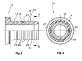
- Fig. 1 shows a half-section through the fitting body 10 of a press fitting, which in addition to the fitting body 10 has a (not shown) compression sleeve, which is known per se.
- the fitting body 10 has a support sleeve 12, on which the end 14 of a pipe 16 to be connected is pushed (see Fig. 2 ).
- the support sleeve 12 has on its outer side 18 a profiling, in the form of circumferential ribs 20. Further, the outer side 18 of the support sleeve 12 is provided with a circumferential receiving groove 22 in which an elastomeric sealing ring 24 is located, sunk in the receiving groove 22 is arranged, that is, not radially over the two the receiving groove 22 axially delimiting ribs 20 projects, but a maximum of the outer surfaces 26 is aligned.
- the ribs 20 ellipse shape or elliptical cross sections, wherein adjacent ribs 20 are offset in the circumferential direction against each other.
- the dimensions of the elliptical ribs 20 are chosen so that the larger of the two ellipse diameter is substantially equal to the inner diameter of the pipe 16 to be connected. This results in those areas in which the outer diameter of the elliptical ribs 20 is smaller than the inner diameter of the pipe to be connected 16, a gap 28 between the ribs 20 and the inner side 30 of the pipe to be connected 16.
- the tube 16 In the compressed state, the tube 16 is compressed by radially acting from the outside forces and thus reliably pressed against the oval or elliptical ribs 20. Thus, in the compressed state the density connection of the tube 16 on the fitting body 10 or on the outer side 18 of its support sleeve 12 is ensured.
- the advantage of the circumferentially offset elliptical or oval ribs 20 can be seen in the fact that the wall of the support sleeve 12 is not reduced over its entire length in a single circumferential angle range. Rather, the reduced diameter portions of the elliptical ribs 20 are on a helical line around the support sleeve 12, which Thar-fi that the support sleeve 12 is sufficiently stable over 360 ° in order to withstand the pressure forces of the tube during compression can.
- the fitting body 10 expediently has plastic or at least its support sleeve 12 is made of plastic. Especially with these materials, a minimum wall thickness is required to make the contact forces sufficient. It is therefore important that the wall thickness reduction envisaged for the realization of the function "leakage before compression" is not located at any point in the axial extent of the support sleeve 12 in one and the same circumferential rotation range but, as provided according to the invention, along the longitudinal extension of the support sleeve 12 is formed in different circumferential angular ranges.
Claims (2)
- Raccord pour un tuyau, en particulier un tuyau en matière plastique ou un tube d'assemblage en matière plastique ou en métal avec- une boîte de raccord (10) comportant une cosse de support (12) sur laquelle le bout d'un tuyau à raccorder (16) peut être poussé,- la cosse de support (12) comportant plusieurs renforts circulants (20) sur son côté extérieur,caractérisés en ce que,- les renforts (20) comportent des zones extérieures (26) qui côtoient une ligne de circonférence qui dévie d'un cercle et ont un déroulement elliptique ou bien ovale, et que- des renforts voisins (20) sont arrangés en direction de circonférence, décalés l'un contre l'autre
- Raccord selon la revendication 1, caractérisé en ce que la cosse de support (12) comporte au moins un joint torique (24) et une rainure d'absorption (22) absorbant le joint torique (24) et que le joint torique (24) ne surmonte pas radialement la rainure d'absorption (22).
Applications Claiming Priority (1)
| Application Number | Priority Date | Filing Date | Title |
|---|---|---|---|
| DE102006057418 | 2006-12-06 |
Publications (2)
| Publication Number | Publication Date |
|---|---|
| EP1930640A1 EP1930640A1 (fr) | 2008-06-11 |
| EP1930640B1 true EP1930640B1 (fr) | 2010-02-24 |
Family
ID=39149386
Family Applications (1)
| Application Number | Title | Priority Date | Filing Date |
|---|---|---|---|
| EP07120970A Not-in-force EP1930640B1 (fr) | 2006-12-06 | 2007-11-19 | Raccord pour un tuyau, en particulier un tuyau en plastique ou un tuyau en alliage de plastique et de métal |
Country Status (3)
| Country | Link |
|---|---|
| EP (1) | EP1930640B1 (fr) |
| AT (1) | ATE458952T1 (fr) |
| DE (1) | DE502007002902D1 (fr) |
Families Citing this family (6)
| Publication number | Priority date | Publication date | Assignee | Title |
|---|---|---|---|---|
| DE102009056975B3 (de) | 2009-12-07 | 2011-05-19 | Viega Gmbh & Co. Kg | Rohrförmiges Bauteil |
| DE202009016975U1 (de) | 2009-12-16 | 2011-04-28 | Uponor Innovation Ab | Fitting für ein Rohr |
| CN212097511U (zh) | 2019-02-20 | 2020-12-08 | 米沃奇电动工具公司 | Pex扩张工具 |
| EP3698942A3 (fr) | 2019-02-20 | 2020-10-28 | Milwaukee Electric Tool Corporation | Outil d'expansion pex |
| CN214726466U (zh) | 2020-11-27 | 2021-11-16 | 米沃奇电动工具公司 | 扩展工具 |
| EP4319959A1 (fr) | 2021-04-09 | 2024-02-14 | Milwaukee Electric Tool Corporation | Outil d'expansion |
Family Cites Families (12)
| Publication number | Priority date | Publication date | Assignee | Title |
|---|---|---|---|---|
| DE20221504U1 (de) * | 1977-11-15 | 2006-02-23 | Uponor Innovation Ab | Pressfitting für Rohre |
| DE10007914C1 (de) | 2000-02-21 | 2001-09-06 | Franz Viegener Ii Gmbh & Co Kg | Fitting oder Armatur zur Herstellung einer Pressverbindung mit einem eingesteckten Rohrende |
| DE20106915U1 (de) | 2001-04-20 | 2002-08-29 | Franz Viegener Ii Gmbh & Co Kg | Rohr, insbesondere Kunststoff- oder Verbundrohr |
| DE20201072U1 (de) | 2001-06-07 | 2003-01-09 | Franz Viegener Ii Gmbh & Co Kg | Stützrohr und Verbindungsanordnung |
| DE20109548U1 (de) | 2001-06-07 | 2002-10-17 | Franz Viegener Ii Gmbh & Co Kg | Stützrohr und Verbindungsanordnung |
| EP1278001B1 (fr) | 2001-07-19 | 2005-04-06 | Geberit Technik Ag | Raccord de compression entre un élément de raccordement et une extrémité de tuyau |
| DE10164568C1 (de) | 2001-12-14 | 2003-06-12 | Mapress Gmbh & Co Kg | Rohrverbindung |
| DK1470356T3 (da) * | 2002-01-28 | 2006-09-25 | Geberit Technik Ag | Presforbindelse |
| DE10217824C1 (de) | 2002-04-15 | 2003-07-24 | Mapress Gmbh & Co Kg | Rohrverbindung |
| DE20300918U1 (de) | 2003-01-22 | 2003-03-20 | Franz Viegener Ii Gmbh & Co Kg | Pressverbindungsanordnung |
| FR2856132B1 (fr) * | 2003-06-10 | 2005-07-22 | Comap | Dispositif d'emboiture de raccord a sertir a gorge de profondeur variable |
| ES2298904T3 (es) | 2005-10-12 | 2008-05-16 | Roth Werke Gmbh | Accesorio para tuberias. |
-
2007
- 2007-11-19 AT AT07120970T patent/ATE458952T1/de active
- 2007-11-19 DE DE502007002902T patent/DE502007002902D1/de active Active
- 2007-11-19 EP EP07120970A patent/EP1930640B1/fr not_active Not-in-force
Also Published As
| Publication number | Publication date |
|---|---|
| DE502007002902D1 (de) | 2010-04-08 |
| EP1930640A1 (fr) | 2008-06-11 |
| ATE458952T1 (de) | 2010-03-15 |
Similar Documents
| Publication | Publication Date | Title |
|---|---|---|
| AT401417B (de) | Schiebehülsen-verbindung für kunststoffrohre | |
| EP2864685B1 (fr) | Dispositif de raccordement pour conduites | |
| DE102006031582B4 (de) | Muffenverbindung | |
| EP1930640B1 (fr) | Raccord pour un tuyau, en particulier un tuyau en plastique ou un tuyau en alliage de plastique et de métal | |
| DE102014011583B3 (de) | Schlauchkupplung | |
| EP2330326B1 (fr) | Composant tubulaire | |
| EP2025988B1 (fr) | Raccord pour un tuyau, en particulier un tuyau en plastique ou un tuyau composite en plastique et métal | |
| EP0214395A1 (fr) | Raccord élastique de tuyaux et spécialement raccord flexible | |
| DE4221175A1 (de) | Verbindungssystem für Rohrleitungen | |
| WO2006000430A2 (fr) | Raccord | |
| DE60020212T2 (de) | Rohrverbindungselement, insbesondere für kunststoffrohre | |
| EP1306601B1 (fr) | Raccords à compression pour la connection d'au moins un tuyau | |
| EP2050994A1 (fr) | Raccord de tuyau | |
| DE2630814B2 (de) | Rohrverbindung für unvorbereitete Enden mit einer Dichtungshulse | |
| DE4002558C2 (de) | Hydraulikzylinder | |
| EP2295842B1 (fr) | Raccord de tuyau destiné à raccorder de manière étanche une extrémité d'un tuyau en matière flexible | |
| DE202011107927U1 (de) | Verbindungsvorrichtung zum Verbinden von zwei Rohren | |
| DE102012005943A1 (de) | Vorrichtung zum Verbinden von zwei Rundkörpern mit unterschiedlichen Außendurchmessern | |
| EP0943854B1 (fr) | Connexion par anneau de serrage | |
| DE202011003529U1 (de) | Vorrichtung zum Verbinden von Rohren | |
| DE102015226513B4 (de) | Bausatz für eine Rohrverbindung und Dichtungs-Ring für eine solche Rohrverbindung | |
| EP2476939A2 (fr) | Raccord pour le raccordement d'une extrémité de tuyau | |
| WO2000028250A1 (fr) | Emmanchement de tuyaux a la presse | |
| EP2430343B1 (fr) | Dispositif d'introduction d'une installation de retenue dans une conduite tubulaire | |
| DE102020124183A1 (de) | Anschlussvorrichtung zum Anschließen eines Rohres mit außenumfangsseitiger Erhebung und Montageverfahren |
Legal Events
| Date | Code | Title | Description |
|---|---|---|---|
| PUAI | Public reference made under article 153(3) epc to a published international application that has entered the european phase |
Free format text: ORIGINAL CODE: 0009012 |
|
| AK | Designated contracting states |
Kind code of ref document: A1 Designated state(s): AT BE BG CH CY CZ DE DK EE ES FI FR GB GR HU IE IS IT LI LT LU LV MC MT NL PL PT RO SE SI SK TR |
|
| AX | Request for extension of the european patent |
Extension state: AL BA HR MK RS |
|
| 17P | Request for examination filed |
Effective date: 20081202 |
|
| AKX | Designation fees paid |
Designated state(s): AT BE BG CH CY CZ DE DK EE ES FI FR GB GR HU IE IS IT LI LT LU LV MC MT NL PL PT RO SE SI SK TR |
|
| GRAP | Despatch of communication of intention to grant a patent |
Free format text: ORIGINAL CODE: EPIDOSNIGR1 |
|
| GRAS | Grant fee paid |
Free format text: ORIGINAL CODE: EPIDOSNIGR3 |
|
| GRAA | (expected) grant |
Free format text: ORIGINAL CODE: 0009210 |
|
| AK | Designated contracting states |
Kind code of ref document: B1 Designated state(s): AT BE BG CH CY CZ DE DK EE ES FI FR GB GR HU IE IS IT LI LT LU LV MC MT NL PL PT RO SE SI SK TR |
|
| REG | Reference to a national code |
Ref country code: GB Ref legal event code: FG4D Free format text: NOT ENGLISH |
|
| REG | Reference to a national code |
Ref country code: CH Ref legal event code: EP |
|
| REG | Reference to a national code |
Ref country code: IE Ref legal event code: FG4D Free format text: LANGUAGE OF EP DOCUMENT: GERMAN |
|
| REF | Corresponds to: |
Ref document number: 502007002902 Country of ref document: DE Date of ref document: 20100408 Kind code of ref document: P |
|
| REG | Reference to a national code |
Ref country code: NL Ref legal event code: VDEP Effective date: 20100224 |
|
| LTIE | Lt: invalidation of european patent or patent extension |
Effective date: 20100224 |
|
| PG25 | Lapsed in a contracting state [announced via postgrant information from national office to epo] |
Ref country code: IS Free format text: LAPSE BECAUSE OF FAILURE TO SUBMIT A TRANSLATION OF THE DESCRIPTION OR TO PAY THE FEE WITHIN THE PRESCRIBED TIME-LIMIT Effective date: 20100624 Ref country code: PT Free format text: LAPSE BECAUSE OF FAILURE TO SUBMIT A TRANSLATION OF THE DESCRIPTION OR TO PAY THE FEE WITHIN THE PRESCRIBED TIME-LIMIT Effective date: 20100625 Ref country code: LT Free format text: LAPSE BECAUSE OF FAILURE TO SUBMIT A TRANSLATION OF THE DESCRIPTION OR TO PAY THE FEE WITHIN THE PRESCRIBED TIME-LIMIT Effective date: 20100224 |
|
| PG25 | Lapsed in a contracting state [announced via postgrant information from national office to epo] |
Ref country code: SI Free format text: LAPSE BECAUSE OF FAILURE TO SUBMIT A TRANSLATION OF THE DESCRIPTION OR TO PAY THE FEE WITHIN THE PRESCRIBED TIME-LIMIT Effective date: 20100224 Ref country code: FI Free format text: LAPSE BECAUSE OF FAILURE TO SUBMIT A TRANSLATION OF THE DESCRIPTION OR TO PAY THE FEE WITHIN THE PRESCRIBED TIME-LIMIT Effective date: 20100224 Ref country code: LV Free format text: LAPSE BECAUSE OF FAILURE TO SUBMIT A TRANSLATION OF THE DESCRIPTION OR TO PAY THE FEE WITHIN THE PRESCRIBED TIME-LIMIT Effective date: 20100224 Ref country code: PL Free format text: LAPSE BECAUSE OF FAILURE TO SUBMIT A TRANSLATION OF THE DESCRIPTION OR TO PAY THE FEE WITHIN THE PRESCRIBED TIME-LIMIT Effective date: 20100224 |
|
| REG | Reference to a national code |
Ref country code: IE Ref legal event code: FD4D |
|
| PG25 | Lapsed in a contracting state [announced via postgrant information from national office to epo] |
Ref country code: ES Free format text: LAPSE BECAUSE OF FAILURE TO SUBMIT A TRANSLATION OF THE DESCRIPTION OR TO PAY THE FEE WITHIN THE PRESCRIBED TIME-LIMIT Effective date: 20100604 Ref country code: CY Free format text: LAPSE BECAUSE OF FAILURE TO SUBMIT A TRANSLATION OF THE DESCRIPTION OR TO PAY THE FEE WITHIN THE PRESCRIBED TIME-LIMIT Effective date: 20100224 Ref country code: EE Free format text: LAPSE BECAUSE OF FAILURE TO SUBMIT A TRANSLATION OF THE DESCRIPTION OR TO PAY THE FEE WITHIN THE PRESCRIBED TIME-LIMIT Effective date: 20100224 Ref country code: GR Free format text: LAPSE BECAUSE OF FAILURE TO SUBMIT A TRANSLATION OF THE DESCRIPTION OR TO PAY THE FEE WITHIN THE PRESCRIBED TIME-LIMIT Effective date: 20100525 Ref country code: IE Free format text: LAPSE BECAUSE OF FAILURE TO SUBMIT A TRANSLATION OF THE DESCRIPTION OR TO PAY THE FEE WITHIN THE PRESCRIBED TIME-LIMIT Effective date: 20100224 Ref country code: NL Free format text: LAPSE BECAUSE OF FAILURE TO SUBMIT A TRANSLATION OF THE DESCRIPTION OR TO PAY THE FEE WITHIN THE PRESCRIBED TIME-LIMIT Effective date: 20100224 Ref country code: RO Free format text: LAPSE BECAUSE OF FAILURE TO SUBMIT A TRANSLATION OF THE DESCRIPTION OR TO PAY THE FEE WITHIN THE PRESCRIBED TIME-LIMIT Effective date: 20100224 Ref country code: SE Free format text: LAPSE BECAUSE OF FAILURE TO SUBMIT A TRANSLATION OF THE DESCRIPTION OR TO PAY THE FEE WITHIN THE PRESCRIBED TIME-LIMIT Effective date: 20100224 |
|
| PG25 | Lapsed in a contracting state [announced via postgrant information from national office to epo] |
Ref country code: BG Free format text: LAPSE BECAUSE OF FAILURE TO SUBMIT A TRANSLATION OF THE DESCRIPTION OR TO PAY THE FEE WITHIN THE PRESCRIBED TIME-LIMIT Effective date: 20100524 Ref country code: CZ Free format text: LAPSE BECAUSE OF FAILURE TO SUBMIT A TRANSLATION OF THE DESCRIPTION OR TO PAY THE FEE WITHIN THE PRESCRIBED TIME-LIMIT Effective date: 20100224 Ref country code: SK Free format text: LAPSE BECAUSE OF FAILURE TO SUBMIT A TRANSLATION OF THE DESCRIPTION OR TO PAY THE FEE WITHIN THE PRESCRIBED TIME-LIMIT Effective date: 20100224 |
|
| PLBE | No opposition filed within time limit |
Free format text: ORIGINAL CODE: 0009261 |
|
| STAA | Information on the status of an ep patent application or granted ep patent |
Free format text: STATUS: NO OPPOSITION FILED WITHIN TIME LIMIT |
|
| PG25 | Lapsed in a contracting state [announced via postgrant information from national office to epo] |
Ref country code: DK Free format text: LAPSE BECAUSE OF FAILURE TO SUBMIT A TRANSLATION OF THE DESCRIPTION OR TO PAY THE FEE WITHIN THE PRESCRIBED TIME-LIMIT Effective date: 20100224 |
|
| 26N | No opposition filed |
Effective date: 20101125 |
|
| PG25 | Lapsed in a contracting state [announced via postgrant information from national office to epo] |
Ref country code: IT Free format text: LAPSE BECAUSE OF FAILURE TO SUBMIT A TRANSLATION OF THE DESCRIPTION OR TO PAY THE FEE WITHIN THE PRESCRIBED TIME-LIMIT Effective date: 20100224 |
|
| BERE | Be: lapsed |
Owner name: UPONOR INNOVATION A.B. Effective date: 20101130 |
|
| PG25 | Lapsed in a contracting state [announced via postgrant information from national office to epo] |
Ref country code: MC Free format text: LAPSE BECAUSE OF NON-PAYMENT OF DUE FEES Effective date: 20101130 |
|
| REG | Reference to a national code |
Ref country code: FR Ref legal event code: ST Effective date: 20110801 |
|
| PG25 | Lapsed in a contracting state [announced via postgrant information from national office to epo] |
Ref country code: BE Free format text: LAPSE BECAUSE OF NON-PAYMENT OF DUE FEES Effective date: 20101130 |
|
| REG | Reference to a national code |
Ref country code: DE Ref legal event code: R119 Ref document number: 502007002902 Country of ref document: DE Effective date: 20110601 Ref country code: DE Ref legal event code: R119 Ref document number: 502007002902 Country of ref document: DE Effective date: 20110531 |
|
| PG25 | Lapsed in a contracting state [announced via postgrant information from national office to epo] |
Ref country code: FR Free format text: LAPSE BECAUSE OF NON-PAYMENT OF DUE FEES Effective date: 20101130 |
|
| PG25 | Lapsed in a contracting state [announced via postgrant information from national office to epo] |
Ref country code: MT Free format text: LAPSE BECAUSE OF FAILURE TO SUBMIT A TRANSLATION OF THE DESCRIPTION OR TO PAY THE FEE WITHIN THE PRESCRIBED TIME-LIMIT Effective date: 20100224 |
|
| REG | Reference to a national code |
Ref country code: CH Ref legal event code: PL |
|
| GBPC | Gb: european patent ceased through non-payment of renewal fee |
Effective date: 20111119 |
|
| PG25 | Lapsed in a contracting state [announced via postgrant information from national office to epo] |
Ref country code: CH Free format text: LAPSE BECAUSE OF NON-PAYMENT OF DUE FEES Effective date: 20111130 Ref country code: LI Free format text: LAPSE BECAUSE OF NON-PAYMENT OF DUE FEES Effective date: 20111130 |
|
| PG25 | Lapsed in a contracting state [announced via postgrant information from national office to epo] |
Ref country code: HU Free format text: LAPSE BECAUSE OF FAILURE TO SUBMIT A TRANSLATION OF THE DESCRIPTION OR TO PAY THE FEE WITHIN THE PRESCRIBED TIME-LIMIT Effective date: 20100825 Ref country code: LU Free format text: LAPSE BECAUSE OF NON-PAYMENT OF DUE FEES Effective date: 20101119 |
|
| PG25 | Lapsed in a contracting state [announced via postgrant information from national office to epo] |
Ref country code: TR Free format text: LAPSE BECAUSE OF FAILURE TO SUBMIT A TRANSLATION OF THE DESCRIPTION OR TO PAY THE FEE WITHIN THE PRESCRIBED TIME-LIMIT Effective date: 20100224 Ref country code: GB Free format text: LAPSE BECAUSE OF NON-PAYMENT OF DUE FEES Effective date: 20111119 |
|
| PG25 | Lapsed in a contracting state [announced via postgrant information from national office to epo] |
Ref country code: DE Free format text: LAPSE BECAUSE OF NON-PAYMENT OF DUE FEES Effective date: 20110531 |
|
| REG | Reference to a national code |
Ref country code: AT Ref legal event code: MM01 Ref document number: 458952 Country of ref document: AT Kind code of ref document: T Effective date: 20121130 |
|
| PG25 | Lapsed in a contracting state [announced via postgrant information from national office to epo] |
Ref country code: AT Free format text: LAPSE BECAUSE OF NON-PAYMENT OF DUE FEES Effective date: 20121130 |